WO2024257710A1 - レーザ装置用フード、レーザ加工装置及びレーザ加工方法 - Google Patents
レーザ装置用フード、レーザ加工装置及びレーザ加工方法 Download PDFInfo
- Publication number
- WO2024257710A1 WO2024257710A1 PCT/JP2024/020968 JP2024020968W WO2024257710A1 WO 2024257710 A1 WO2024257710 A1 WO 2024257710A1 JP 2024020968 W JP2024020968 W JP 2024020968W WO 2024257710 A1 WO2024257710 A1 WO 2024257710A1
- Authority
- WO
- WIPO (PCT)
- Prior art keywords
- cylindrical portion
- hood
- laser
- nozzle
- axial direction
- Prior art date
- Legal status (The legal status is an assumption and is not a legal conclusion. Google has not performed a legal analysis and makes no representation as to the accuracy of the status listed.)
- Ceased
Links
Images






Classifications
-
- B—PERFORMING OPERATIONS; TRANSPORTING
- B23—MACHINE TOOLS; METAL-WORKING NOT OTHERWISE PROVIDED FOR
- B23K—SOLDERING OR UNSOLDERING; WELDING; CLADDING OR PLATING BY SOLDERING OR WELDING; CUTTING BY APPLYING HEAT LOCALLY, e.g. FLAME CUTTING; WORKING BY LASER BEAM
- B23K26/00—Working by laser beam, e.g. welding, cutting or boring
- B23K26/14—Working by laser beam, e.g. welding, cutting or boring using a fluid stream, e.g. a jet of gas, in conjunction with the laser beam; Nozzles therefor
- B23K26/1462—Nozzles; Features related to nozzles
- B23K26/1488—Means for protecting nozzles, e.g. the tip surface
-
- B—PERFORMING OPERATIONS; TRANSPORTING
- B23—MACHINE TOOLS; METAL-WORKING NOT OTHERWISE PROVIDED FOR
- B23K—SOLDERING OR UNSOLDERING; WELDING; CLADDING OR PLATING BY SOLDERING OR WELDING; CUTTING BY APPLYING HEAT LOCALLY, e.g. FLAME CUTTING; WORKING BY LASER BEAM
- B23K26/00—Working by laser beam, e.g. welding, cutting or boring
- B23K26/12—Working by laser beam, e.g. welding, cutting or boring in a special environment or atmosphere, e.g. in an enclosure
- B23K26/127—Working by laser beam, e.g. welding, cutting or boring in a special environment or atmosphere, e.g. in an enclosure in an enclosure
-
- B—PERFORMING OPERATIONS; TRANSPORTING
- B23—MACHINE TOOLS; METAL-WORKING NOT OTHERWISE PROVIDED FOR
- B23K—SOLDERING OR UNSOLDERING; WELDING; CLADDING OR PLATING BY SOLDERING OR WELDING; CUTTING BY APPLYING HEAT LOCALLY, e.g. FLAME CUTTING; WORKING BY LASER BEAM
- B23K26/00—Working by laser beam, e.g. welding, cutting or boring
- B23K26/70—Auxiliary operations or equipment
-
- B—PERFORMING OPERATIONS; TRANSPORTING
- B23—MACHINE TOOLS; METAL-WORKING NOT OTHERWISE PROVIDED FOR
- B23K—SOLDERING OR UNSOLDERING; WELDING; CLADDING OR PLATING BY SOLDERING OR WELDING; CUTTING BY APPLYING HEAT LOCALLY, e.g. FLAME CUTTING; WORKING BY LASER BEAM
- B23K26/00—Working by laser beam, e.g. welding, cutting or boring
- B23K26/12—Working by laser beam, e.g. welding, cutting or boring in a special environment or atmosphere, e.g. in an enclosure
- B23K26/123—Working by laser beam, e.g. welding, cutting or boring in a special environment or atmosphere, e.g. in an enclosure in an atmosphere of particular gases
-
- B—PERFORMING OPERATIONS; TRANSPORTING
- B23—MACHINE TOOLS; METAL-WORKING NOT OTHERWISE PROVIDED FOR
- B23K—SOLDERING OR UNSOLDERING; WELDING; CLADDING OR PLATING BY SOLDERING OR WELDING; CUTTING BY APPLYING HEAT LOCALLY, e.g. FLAME CUTTING; WORKING BY LASER BEAM
- B23K26/00—Working by laser beam, e.g. welding, cutting or boring
- B23K26/12—Working by laser beam, e.g. welding, cutting or boring in a special environment or atmosphere, e.g. in an enclosure
- B23K26/127—Working by laser beam, e.g. welding, cutting or boring in a special environment or atmosphere, e.g. in an enclosure in an enclosure
- B23K26/128—Laser beam path enclosures
-
- B—PERFORMING OPERATIONS; TRANSPORTING
- B23—MACHINE TOOLS; METAL-WORKING NOT OTHERWISE PROVIDED FOR
- B23K—SOLDERING OR UNSOLDERING; WELDING; CLADDING OR PLATING BY SOLDERING OR WELDING; CUTTING BY APPLYING HEAT LOCALLY, e.g. FLAME CUTTING; WORKING BY LASER BEAM
- B23K26/00—Working by laser beam, e.g. welding, cutting or boring
- B23K26/14—Working by laser beam, e.g. welding, cutting or boring using a fluid stream, e.g. a jet of gas, in conjunction with the laser beam; Nozzles therefor
- B23K26/142—Working by laser beam, e.g. welding, cutting or boring using a fluid stream, e.g. a jet of gas, in conjunction with the laser beam; Nozzles therefor for the removal of by-products
-
- B—PERFORMING OPERATIONS; TRANSPORTING
- B23—MACHINE TOOLS; METAL-WORKING NOT OTHERWISE PROVIDED FOR
- B23K—SOLDERING OR UNSOLDERING; WELDING; CLADDING OR PLATING BY SOLDERING OR WELDING; CUTTING BY APPLYING HEAT LOCALLY, e.g. FLAME CUTTING; WORKING BY LASER BEAM
- B23K26/00—Working by laser beam, e.g. welding, cutting or boring
- B23K26/14—Working by laser beam, e.g. welding, cutting or boring using a fluid stream, e.g. a jet of gas, in conjunction with the laser beam; Nozzles therefor
- B23K26/1435—Working by laser beam, e.g. welding, cutting or boring using a fluid stream, e.g. a jet of gas, in conjunction with the laser beam; Nozzles therefor involving specially adapted flow-control means
- B23K26/1438—Working by laser beam, e.g. welding, cutting or boring using a fluid stream, e.g. a jet of gas, in conjunction with the laser beam; Nozzles therefor involving specially adapted flow-control means for directional control
-
- B—PERFORMING OPERATIONS; TRANSPORTING
- B23—MACHINE TOOLS; METAL-WORKING NOT OTHERWISE PROVIDED FOR
- B23K—SOLDERING OR UNSOLDERING; WELDING; CLADDING OR PLATING BY SOLDERING OR WELDING; CUTTING BY APPLYING HEAT LOCALLY, e.g. FLAME CUTTING; WORKING BY LASER BEAM
- B23K26/00—Working by laser beam, e.g. welding, cutting or boring
- B23K26/14—Working by laser beam, e.g. welding, cutting or boring using a fluid stream, e.g. a jet of gas, in conjunction with the laser beam; Nozzles therefor
- B23K26/1462—Nozzles; Features related to nozzles
-
- B—PERFORMING OPERATIONS; TRANSPORTING
- B23—MACHINE TOOLS; METAL-WORKING NOT OTHERWISE PROVIDED FOR
- B23K—SOLDERING OR UNSOLDERING; WELDING; CLADDING OR PLATING BY SOLDERING OR WELDING; CUTTING BY APPLYING HEAT LOCALLY, e.g. FLAME CUTTING; WORKING BY LASER BEAM
- B23K26/00—Working by laser beam, e.g. welding, cutting or boring
- B23K26/14—Working by laser beam, e.g. welding, cutting or boring using a fluid stream, e.g. a jet of gas, in conjunction with the laser beam; Nozzles therefor
- B23K26/1462—Nozzles; Features related to nozzles
- B23K26/1464—Supply to, or discharge from, nozzles of media, e.g. gas, powder, wire
-
- B—PERFORMING OPERATIONS; TRANSPORTING
- B23—MACHINE TOOLS; METAL-WORKING NOT OTHERWISE PROVIDED FOR
- B23K—SOLDERING OR UNSOLDERING; WELDING; CLADDING OR PLATING BY SOLDERING OR WELDING; CUTTING BY APPLYING HEAT LOCALLY, e.g. FLAME CUTTING; WORKING BY LASER BEAM
- B23K26/00—Working by laser beam, e.g. welding, cutting or boring
- B23K26/16—Removal of by-products, e.g. particles or vapours produced during treatment of a workpiece
Definitions
- the present invention relates to a hood for a laser device, a laser processing device, and a laser processing method.
- Laser processing apparatuses that irradiate a workpiece (object to be processed) with a laser to perform laser processing such as annealing are known (see, for example, Japanese Patent Application Laid-Open No. 2003-233634).
- the workpiece may be exposed to a gas such as an inert gas to perform laser processing.
- the workpiece is covered with a hood having a nozzle at the top for supplying gas, and the inside of the hood is purged with the gas supplied from the nozzle. Then, a laser is irradiated into the hood through the protective glass on the top of the hood to perform laser processing on the workpiece.
- the nozzle is located at the top of the hood (the end in the laser irradiation direction), so a single gas flow is formed inside the hood in the laser irradiation direction.
- This gas flow can stir up and stir up dust such as fine particles generated from the workpiece by laser processing, causing it to adhere to the protective glass on the top of the hood. If dust adheres to the protective glass, the laser passing through the protective glass will be attenuated.
- the present invention was made in consideration of the above circumstances, and aims to suppress laser attenuation.
- the present invention relates to a hood for a laser device, A cylindrical portion along an axial direction; a transmission portion provided at one axial end of the cylindrical portion and transmitting a laser; an opening provided at the other axial end of the cylindrical portion; a nozzle for supplying gas to an inside of the cylindrical portion; Equipped with The nozzle is disposed in a central portion in the axial direction and in a portion in the circumferential direction of the cylindrical portion.
- the present invention makes it possible to suppress laser attenuation.
- FIG. 1 is a schematic diagram of a laser processing apparatus according to an embodiment
- FIG. 11 is a cross-sectional view of a hood according to a modified example of the embodiment.
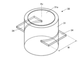
- FIG. 11 is a perspective view of a hood according to a modified example of the embodiment.
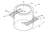
- FIG. 11 is a perspective view of a hood according to a modified example of the embodiment.
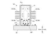
- FIG. 2 is a diagram showing a gas flow within a hood according to an embodiment.
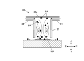
- FIG. 1 illustrates gas flow within a conventional hood.
- FIG. 2 is a diagram showing a gas flow within a hood according to an embodiment.
- FIG. 11 is a diagram showing a gas flow in a hood according to a modified example.
- FIG. 1 illustrates gas flow within a conventional hood.
- FIG. 2 is a diagram showing a gas flow within a hood according to an embodiment.
- FIG. 11 is a diagram showing a gas flow in a hood according to a modified example.
- FIG. 11 is a diagram showing a gas flow within a hood according to a modified example of the embodiment.
- FIG. 11 is a diagram showing a gas flow within a hood according to a modified example of the embodiment.
- FIG. FIG. FIG. FIG. FIG. FIG. FIG. FIG. FIG. FIG. FIG. FIG. 11 is a cross-sectional view of a hood according to a modified example of the embodiment.
- FIG. 11 is a cross-sectional view of a hood according to a modified example of the embodiment.
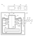
- FIG. 13 is a diagram showing a laser processing apparatus according to a modified example of the embodiment.
- FIG. 1 is a schematic diagram of a laser processing device 1 according to the present embodiment.
- the laser processing apparatus 1 irradiates a workpiece WP, which is an object to be processed, with a laser to perform processing such as annealing, welding, etc.
- the material of the workpiece WP is not particularly limited, but is, for example, silicon, silicon carbide, etc.
- the laser processing apparatus 1 includes a laser irradiation unit 10 , a support table (stage) 20 , a hood 30 , a gas supply unit 40 , and a control unit 50 .
- the laser irradiation unit 10 includes a laser oscillator and an optical system (not shown).
- the laser irradiation unit 10 irradiates a predetermined laser beam downward according to the type of processing.
- the support table 20 is disposed below the laser irradiation unit 10 and supports the workpiece WP on its upper surface. At least one of the laser irradiation unit 10 and the support table 20 may have a movable part so that the laser irradiation position on the workpiece WP can be adjusted.
- the hood 30 is disposed below the laser irradiation unit 10 and above the support table 20, and covers the workpiece WP placed on the support table 20.
- a predetermined gas is supplied into the hood 30 from a gas supply unit 40.
- the hood 30 exposes the workpiece WP to a predetermined gas atmosphere while allowing the laser from the laser irradiation unit 10 above to pass through.
- the specific configuration of the hood 30 will be described later.
- the gas supply unit 40 supplies (applies) a specified gas into the hood 30.
- the gas supplied may be, for example, an inert gas such as nitrogen or oxygen.
- the gas supply unit 40 has a gas source 41, which is a gas pump or a gas cylinder, a valve 42, and piping 43 that connects the gas source 41 to the hood 30 (each nozzle 34) via the valve 42.
- the control unit 50 is configured, for example, by a CPU (Central Processing Unit) and controls each part of the laser processing device 1. Specifically, the control unit 50 controls the operation of the laser irradiation unit 10 to irradiate the laser, and controls the operation of the valve 42 and gas source 41 of the gas supply unit 40 to supply a specified gas to the hood 30. Each part of the gas supply unit 40 may be manually controlled.
- a CPU Central Processing Unit
- the hood 30 includes a cylindrical portion 31 and a nozzle 34 .
- the tubular portion 31 is formed in a cylindrical shape having a central axis Ax along the up-down direction.
- the shape of the tubular portion 31 is not limited to a cylindrical shape as long as it is cylindrical.
- the direction along the central axis Ax may be referred to as the “axial direction,” and the direction perpendicular to the axial direction may be referred to as the “radial direction.”
- the direction in which the nozzle 34 is erected in the hood 30 (the left-right direction on the paper in FIG. 1, etc.) may be referred to as the “left-right (direction).”
- the upper end (one end) of the cylindrical portion 31 is closed and has a protective glass 31a (transmitting portion) that transmits a laser.
- the protective glass 31a is provided over substantially the entire upper end surface of the cylindrical portion 31.
- the protective glass 31a transmits most of the laser irradiated from the laser irradiation unit 10 above into the hood 30 (cylindrical portion 31).
- the protective glass 31a prevents dust PA such as fine particles (see FIGS. 4A, 4B, etc.) generated from the workpiece WP by laser processing from adhering to the optical system of the laser irradiation unit 10.
- the lower end (the other end) of the cylindrical portion 31 is an opening 31b that is open on the entire surface.
- the opening 31b faces the upper surface of the support base 20 in the vertical direction with a predetermined gap interposed between the opening 31b and the upper surface of the support base 20.
- the nozzle 34 is provided on the outer circumferential surface of the cylindrical portion 31 and blows gas into the inside of the cylindrical portion 31 .
- a total of four nozzles 34 are provided, with two (two sets) of nozzles arranged side by side in the axial direction, two of which form a pair on the left and right sides of the radial direction of the cylindrical portion 31. That is, one set (two nozzles) of nozzles 34a is provided on the upper side, and one set (two nozzles) of nozzles 34b is provided on the lower side.
- the nozzles 34 are arranged in parallel in the radial direction.
- the number and basic arrangement of the nozzles 34 are not particularly limited as long as they include the nozzles 34 arranged in the center of the axial direction, which will be described later.
- the nozzles 34 may be provided on only one side that does not form a pair in the radial direction (i.e., an odd number), or one or more pairs may be provided, or the two nozzles located on opposite sides in the radial direction may not face each other (their axial positions may be different).
- the two nozzles 34 facing each other on the left and right may not be symmetrical or axially symmetrical with each other.
- each nozzle 34 may be divided into a plurality of nozzles in the width direction (see FIG. 3B).
- the two nozzles 34 may face each other in a plane perpendicular to the axial direction of the cylindrical portion 31, and may not be aligned along the radial direction.
- each nozzle 34 is the center of the cylindrical portion 31.
- the "center” in the axial direction refers to a portion of the cylindrical portion 31 excluding the upper and lower ends. In other words, it is sufficient that each nozzle 34 is spaced apart from the upper and lower ends of the cylindrical portion 31.
- each nozzle 34 is disposed at an axial position defined by the following first length L1 and second length L2.
- the first length L1 is the axial length from the upper end (one end) of the cylindrical portion 31 to the nozzle 34
- the second length L2 is the axial length from the lower end (the other end) of the cylindrical portion 31 to the nozzle 34.
- the first length L1 and the second length L2 may be any length other than zero. For ease of understanding, FIG.
- the "axial position of the nozzle 34" refers to the center position of the portion of the nozzle 34 that opens into the inner diameter of the cylindrical portion 31.
- the first length L1 may be the distance from the upper end of the inner diameter (hole) of the nozzle 34
- the second length L2 may be the distance from the lower end of the inner diameter of the nozzle 34.
- a first axial length L1 from the upper end of the cylindrical portion 31 to each nozzle 34 satisfies the following formula (3).
- D is the inner diameter of the tubular portion 31.
- D may be, for example, an equivalent diameter (the diameter of the cylindrical tubular portion 31 having the same cross-sectional area) or may be the minimum or maximum width of the cross section perpendicular to the axial direction.
- the first length L1 is preferably equal to or greater than 50 mm.
- a second axial length L2 from the lower end of the cylindrical portion 31 to each nozzle 34 satisfies the following formula (4).
- the second length L2 is preferably equal to or greater than 50 mm. More preferably, the second length L2 satisfies the following formula (7). L2 ⁇ 0.5D (7)
- FIGS. 3A and 3B illustrate a hood 30 in which only one set of nozzles 34 is provided in the axial direction.
- the "width W of the nozzle 34” refers to the length along a direction perpendicular to the axial direction of the portion of the nozzle 34 that opens into the inner diameter (hole) of the cylindrical portion 31.
- the center of the nozzle 34 in the width direction does not have to coincide with the center of the cylindrical portion 31 in the same direction (i.e., the central axis Ax).
- the nozzle 34 may be composed of a plurality of partial nozzles 34c arranged in parallel in the width direction.
- the nozzles 34 may include nozzles that are not radially arranged with respect to the central axis Ax of the cylindrical portion 31 when viewed in the axial direction.
- the nozzles 34 may be inclined obliquely with respect to the axial direction. In this case, the two nozzles 34 in a pair, left and right, may face in different oblique directions (for example, obliquely upward and obliquely downward).
- the axial length (thickness) of the inner diameter (hole) of the nozzle 34 is not particularly limited, but is preferably sufficiently small relative to the axial height of the cylindrical portion 31 .
- the length of the inner diameter (hole portion) of the nozzle 34 along the gas flow perpendicular to the width direction is not particularly limited, but it is preferable that the nozzle 34 has a predetermined run-up length so that a uniform flow is formed in the width direction to a certain extent within the nozzle 34.
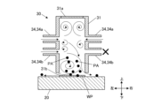
- each nozzle 34 of the hood 30 is disposed in the axial center of the cylindrical portion 31. Therefore, as shown in FIG. 4A, multiple layers of vortex gas flows are formed in the axial direction within the cylindrical portion 31.
- the control unit 50 drives the laser irradiation unit 10 to irradiate a laser beam downward from the laser irradiation unit 10.
- This laser beam passes through the protective glass 31a of the hood 30 and is irradiated into the cylindrical portion 31, and performs a predetermined laser processing on the workpiece WP placed in the opening 31b.
- At least the hood 30 and the support base 20 are housed in a chamber (not shown), and gas leaking from the opening 31b of the hood 30 is sealed in the chamber. The gas in the chamber is exhausted to the outside through an exhaust line connected to the chamber.
- the workpiece WP is processed by the laser in a state in which multiple layers of gas flow are formed in the axial direction inside the hood 30 (cylindrical portion 31).
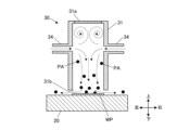
- dust PA generated from the workpiece WP was stirred up by the gas flow and sometimes adhered to the protective glass 81a at the upper end of the hood 80.
- the dust PA adhered to the protective glass 81a attenuates the laser that passes through the protective glass 81a.
- the upper gas flow can prevent the dust PA from approaching the protective glass 31a. This makes it possible to prevent the dust PA from adhering to the protective glass 31a, and therefore to suppress laser attenuation.
- the gas supply amounts may be different between the opposing left and right nozzles 34. Even in this case, even if the balance of the gas flows between the left and right is lost, at least two layers of gas flows can be formed in the axial direction.
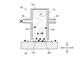
- Fig. 5B only one set of nozzles 34 may be provided. In this case, the gas flow downward does not have to be vortex-shaped, as shown in Fig. 6A. Also, as shown in Fig. 6B, even when there is only one set of nozzles 34, the gas supply amounts may be different between the left and right nozzles 34.
- the nozzle 34 of the hood 30 is disposed in the axial center portion of the cylindrical portion 31.
- the nozzle 34 is disposed in an axial position spaced apart from the upper and lower ends of the cylindrical portion 31. Therefore, the gas supplied from the nozzle 34 forms at least two layers of gas flow in the axial direction inside the cylindrical portion 31. This makes it possible to suppress adhesion of the dust PA to the protective glass 31a, and therefore makes it possible to suppress attenuation of the laser.
- the nozzles 34 are disposed in a portion of the circumferential direction of the cylindrical portion 31. In other words, the nozzles 34 are not formed over the entire circumference of the cylindrical portion 31. Therefore, gas is likely to escape vertically in the inner portion of the circumferential surface of the cylindrical portion 31 where the nozzles 34 are not formed. This makes it possible to favorably form vertical vortices that swirl in the vertical direction.
- the first axial length L1 from the upper end of the cylindrical portion 31 to the nozzle 34 satisfies the above-mentioned formula (3), so that a gas flow above the nozzle 34 can be more reliably formed. Therefore, adhesion of dust PA to the protective glass 31a can be more reliably suppressed.
- the second axial length L2 from the lower end of the cylindrical portion 31 to the nozzle 34 satisfies the above-mentioned formula (4), so that a gas flow below the nozzle 34 can be more reliably formed. Therefore, adhesion of dust PA to the protective glass 31a can be more reliably suppressed.
- the width W of the nozzle along the direction perpendicular to the axial direction satisfies the above-mentioned formula (5), so at least two layers of gas flow in the axial direction can be suitably formed in the width direction within the cylindrical portion 31. Therefore, adhesion of dust PA to the protective glass 31a can be more reliably suppressed.
- the nozzles 34 include a pair of nozzles facing each other in a plane perpendicular to the axial direction. This allows the gas flows to collide in a plane perpendicular to the axial direction, and effectively forms vertical vortices that swirl in the vertical direction.
- the nozzles 34 do not have to be arranged radially with respect to the central axis Ax of the cylindrical portion 31 when viewed from the axial direction. Even if the nozzles 34 are not arranged radially, vertical vortices that swirl in the vertical direction can be formed.
- each part of the analysis model is as follows: Hood shape Total height: 258mm Inner diameter D: 160 mm First length L1: 103 mm Axial distance between upper and lower nozzles: 54 mm Axial height of each nozzle inlet: 2 mm Nozzle width W: 136 mm Left-right distance L3 between the ends of the two nozzles (see FIG.
- the first length L1 and the axial distance between the upper and lower nozzles are the lengths to the blowing ports (holes) of each nozzle.
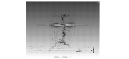
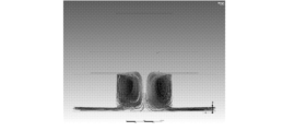
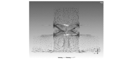
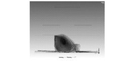
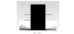
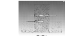
- Figures 7A to 10C show contour diagrams of the analysis results.
- Figures 7A to 7C show model 1
- Figures 8A to 8C show model 2
- Figures 9A to 9C show model 3
- Figures 10A to 10C show the analysis results for a conventional hood 80.
- (a) shows the path line from the bottom of the hood (e.g., at a height of 50 mm)
- (b) shows the gas (e.g., nitrogen) concentration distribution
- (c) is a velocity vector diagram.
- the top and bottom and left and right of the paper correspond to the top and bottom and left and right of the hood.
- Model 1 hood 30 without the lower nozzle set.
- the gas flow forms a vortex below the nozzle 34, so that the dust PA below the hood 30 has difficulty reaching the protective glass 31a.
- the gas concentration inside the hood 30 is generally high. Two layers of vortex gas flows are formed above and below the nozzle 34 .
- Model 2 equal gas amount balance between the left and right.
- the gas flow forms a vortex below the lower nozzle 34b, and the dust PA below the hood 30 has difficulty reaching the protective glass 31a or the upper nozzle 34a.
- the gas concentration inside the hood 30 is generally high. Three layers of vortex gas flows are formed above and below the upper nozzles 34a, below the lower nozzles 34b, and between the two sets of nozzles 34, one above the other.
- Model 3 uneven gas volume balance between the left and right.
- the gas flow forms a vortex below the lower nozzle 34b, and the dust PA below the hood 30 has difficulty reaching the protective glass 31a or the upper nozzle 34a.
- the gas inside the hood 30 exits from the side where the lower nozzle 34b is blowing more strongly. ⁇ Three layers of vortex gas flow are formed above and below.
- the gas flow is a vortex flow with only one layer above and below, and there is a risk that the dust PA at the bottom of the hood 30 will be sucked up onto the protective glass 31a.
- the gas concentration inside the hood 30 is generally high.
- Models 1 to 3 which have three gas layers above and below, are expected to be more effective in preventing the adhesion of dust PA than Model 1, which has two gas layers above and below.
- Model 1 unlike Models 2 and 3, there is a risk that the dust PA is not being discharged properly.
- Gas purging inside the hood 30 is performed appropriately in all of models 1 to 3.
- the main gas application combinations that can be expected to prevent the adhesion of dust PA are shown in Table 2 below. As shown in Table 2, it is preferable that at least one of the upper nozzles 34a applies gas at a "strong" level. Of the combinations in Table 2, No. 1 and No. 2 provided the most desirable results. It is believed that the same effect can be obtained even if the difference in gas application between the left and right sides of each nozzle set is reversed. In addition, when three or more nozzle sets are provided, the pattern of the third and subsequent sets affects the magnitude of the dust PA adhesion prevention effect, but does not affect the presence or absence of said effect.
- the present invention is not limited to the above embodiment.
- the laser is irradiated along the axial direction of the hood 30, but the laser may be inclined with respect to the axial direction.
- a regulator 44 adjusts the blowing pressure from a gas source 41 such as a cylinder.
- the opening/closing valve 45 switches blowing ON/OFF.
- the flow rate control valves 46 are disposed at the upper and lower stages, and adjust the flow rate of the blown gas separately for the upper and lower stages.
- a laser beam emitted from a laser oscillator 11 is passed through an optical system 12 to have its shape and output adjusted, and then the laser irradiation position is controlled by a galvano scanner 13.
- the hood 30 is fixed to a chamber 21 arranged in an enclosure 22.
- the support table (stage) 20 on which the workpiece WP is placed is position-controlled and positioned relative to the hood 30 during processing. At this time, the axial gap between the lower end of the hood 30 and the upper surface of the support table 20 is set to a very short distance (about 2 mm in an actual machine).
- each of the above components is controlled by a control unit 50 (see FIG. 1).
- the laser processing apparatus according to the present invention can be widely applied to laser processing of a workpiece in a gas atmosphere, regardless of the type of processing or the material of the workpiece.
- the details shown in the above embodiment can be modified as appropriate without departing from the spirit of the invention.
- the present invention is useful for suppressing laser attenuation.
- Laser processing device 10 Laser irradiation unit (laser irradiation means) 20 Support stand 30 Hood (laser device hood) 31 Cylindrical portion 31a Protective glass (transmitting portion) 31b Opening 34 Nozzle 34a Upper nozzle 34b Lower nozzle 34c Partial nozzle 40 Gas supply unit (gas supply means) 41 Gas source 42 Valve 43 Pipe 50 Control unit 80 Conventional hood 81 Conventional cylindrical portion 81a Conventional protective glass 84 Conventional nozzle Ax Central axis D Inner diameter PA Particle W Width WP Workpiece
Landscapes
- Engineering & Computer Science (AREA)
- Physics & Mathematics (AREA)
- Optics & Photonics (AREA)
- Plasma & Fusion (AREA)
- Mechanical Engineering (AREA)
- Laser Beam Processing (AREA)
Abstract
Description
この種のレーザ加工装置では、ワークを不活性ガス等のガスに晒してレーザ加工を行う場合がある。このような場合には、例えばガスを供給するノズルを最上部に有するフードでワークを覆い、ノズルから供給したガスでフード内をパージする。そして、フード上面の保護ガラスを通じてフード内にレーザを照射し、ワークをレーザ加工する。
軸方向に沿った筒状部と、
前記筒状部のうち軸方向の一端に設けられ、レーザを透過させる透過部と、
前記筒状部のうち軸方向の他端に設けられた開口部と、
前記筒状部の内部にガスを供給するノズルと、
を備え、
前記ノズルは、前記筒状部のうち、軸方向の中央部かつ周方向の一部に配置される。
図1は、本実施形態に係るレーザ加工装置1の模式図である。
図1に示すように、本実施形態に係るレーザ加工装置1は、加工対象物のワークWPにレーザを照射してアニールや溶接等の加工を施す。ワークWPの材質は、特に限定はされないが、例えばシリコンやシリコンカーバイド等である。
具体的に、レーザ加工装置1は、レーザ照射部10と、支持台(ステージ)20と、フード30と、ガス供給部40と、制御部50とを備える。
支持台20は、レーザ照射部10の下方に配置され、上面でワークWPを支持する。
なお、レーザ照射部10及び支持台20の少なくとも一方は、ワークWP上のレーザ照射位置を調整可能なように、可動部を有していてもよい。
フード30の具体構成については後述する。
図1に示すように、フード30は、筒状部31とノズル34とを備える。
筒状部31は、上下方向に沿った中心軸Axを有する円筒状に形成されている。ただし、筒状部31の形状は、筒状であればよく、円筒状に限定されない。
以下、中心軸Axに沿った方向を「軸方向」といい、軸方向に直交する方向を「径方向」という場合がある。また、フード30におけるノズル34の立設方向(図1等の紙面左右方向)を「左右(方向)」という場合がある。
保護ガラス31aは、筒状部31の上端面の略全面に亘って設けられている。保護ガラス31aは、上方のレーザ照射部10から照射されたレーザの大部分をフード30(筒状部31)内に透過させる。また、保護ガラス31aは、レーザ加工によってワークWPから生じる微粒子等の粉じんPA(図4A、図4B等参照)がレーザ照射部10の光学系に付着することを防止する。
開口部31bは、支持台20の上面との間に所定の隙間を介在させた状態で、当該支持台20の上面と上下に対向している。
本実施形態のノズル34は、筒状部31の径方向に左右で組をなして対向する2つが、軸方向に2つ(2組)並設され、合計4つが設けられている。つまり、上側のノズル34aが1組(2つ)、下側のノズル34bが1組(2つ)設けられている。各ノズル34は、径方向に平行に配置されている。
ただし、ノズル34は、後述する軸方向の中央部に配置されたものを含んでいれば、その数量及び基本配置は特に限定されない。例えば、ノズル34は、径方向に組をなさない片側だけが設けられても(すなわち奇数個でも)よいし、1組又は3組以上が設けられてもよいし、径方向の反対側に位置する2つが対向していなくてもよい(軸方向の位置が異なっていてもよい)。左右に対向する2つのノズル34が互いに左右対称又は軸対称でなくてもよい。また、後述するように、各ノズル34は幅方向に複数に分割されていてもよい(図3B参照)。また、2つのノズル34が左右に対向する場合、当該2つのノズル34は、筒状部31の軸方向に直交する面内で対向していればよく、径方向に沿っていなくてもよい。
換言すれば、各ノズル34は、以下の第1長さL1及び第2長さL2で規定される軸方向の位置に配置される。第1長さL1は筒状部31の上端(一端)からノズル34までの軸方向の長さであり、第2長さL2は筒状部31の下端(他端)からノズル34までの軸方向の長さである。第1長さL1及び第2長さL2はゼロでなければよい。
なお、図2では、分かり易さのために、ノズル34が軸方向に1組だけ設けられたフード30を例示している。
ここで、「ノズル34の軸方向の位置」とは、ノズル34のうち、筒状部31の内径に開口する部分の中心位置をいう。ただし、第1長さL1はノズル34の内径(孔部)における上端からの距離としてもよいし、第2長さL2はノズル34の内径における下端からの距離としてもよい。
L1≧0.3D ・・・(3)
より好ましくは、第1長さL1は、以下の式(6)を満足する。
L1≧0.5D ・・・(6)
ただし、Dは筒状部31の内径である。筒状部31が角筒形の場合、Dは例えば相当直径(断面積が等しい円筒形の筒状部31の直径)でもよいし、軸方向と直交する断面の最小幅又は最大幅でもよい。
あるいは、第1長さL1は、50mm以上であるのが好ましい。
L2≧0.3D ・・・(4)
あるいは、第2長さL2は、50mm以上であるのが好ましい。
より好ましくは、第2長さL2は、以下の式(7)を満足する。
L2≧0.5D ・・・(7)
W≧0.3D ・・・(5)
なお、図3A、図3Bでは、分かり易さのために、ノズル34が軸方向に1組だけ設けられたフード30を例示している。
ここで、「ノズル34の幅W」とは、ノズル34のうち、筒状部31の内径(孔部)に開口する部分における、軸方向に直交する方向に沿った長さをいう。なお、ノズル34の幅方向(幅Wに沿った方向)における中心は、筒状部31における同方向の中心(すなわち中心軸Ax)と一致していなくてもよい。
また、図11A、図11Bに示すように、ノズル34は、軸方向に対して斜めに傾斜していてもよい。この場合、組をなす左右2つのノズル34が、互いに異なる斜め方向(例えば斜め上向きと斜め下向き)を向いていてもよい。
また、ノズル34の内径(孔部)における軸方向の長さ(厚さ)は、特に限定はされないが、筒状部31の軸方向高さに対して十分に小さいのが好ましい。
また、ノズル34の内径(孔部)のうち、幅方向と直交するガス流に沿った長さ(本実施形態では径方向に沿った長さ)は、特に限定はされないが、ノズル34内で幅方向に一定程度の均一な流れが形成されるように、所定の助走長さを有するのが好ましい。
図1に示すように、レーザ加工装置1でワークWPをレーザ加工する際には、まず、ワークWPの被加工部が平面視でフード30(開口部31b)の内側に位置するように、当該ワークWPを支持台20の上面に配置する。
そして、ガス供給部40により、フード30に不活性ガス等の所定のガスを供給してフード30内をパージする。このガスは、各ノズル34からフード30の筒状部31内に所定の流量(例えば約10L/min)で供給され、フード30の筒状部31内にガス流を形成する。
なお、少なくともフード30と支持台20は図示しないチャンバーに収容されており、フード30の開口部31bから漏れたガスはチャンバー内に封入される。チャンバー内のガスは、チャンバーに接続された排気ラインから外部に排気される。
すなわち、図4Bに示すように、従来のフード80では、ノズル84が筒状部81の略最上部に配置されていたため、筒状部81内には軸方向に単一のガス流しか形成されていなかった。そのため、ワークWPから生じる粉じんPAがガス流によって巻き上げられ、フード80上端の保護ガラス81aに付着することがあった。保護ガラス81aに付着した粉じんPAは、当該保護ガラス81aを透過するレーザを減衰させてしまう。
この点、本実施形態では、フード30内において軸方向に複数層のガス流を形成することにより、下側のガス流で粉じんPAが巻き上げられても、それよりも上側のガス流によって当該粉じんPAの保護ガラス31aへの接近を抑制できる。これにより、粉じんPAが保護ガラス31aに付着することを抑制でき、ひいてはレーザの減衰を抑制できる。
したがって、例えば図5Aに示すように、対向する左右のノズル34でガス供給量を異ならせてもよい。この場合でも、左右でのガス流のバランスは崩れても、軸方向に少なくとも2層のガス流は形成できる。
あるいは図5Bに示すように、ノズル34を1組だけ設けることとしてもよい。この場合において、図6Aに示すように、下側へのガス流は渦状でなくてもよい。また、図6Bに示すように、ノズル34が1組の場合でも、左右のノズル34でガス供給量を異ならせてもよい。
以上のように、本実施形態によれば、フード30のノズル34は、筒状部31のうち軸方向の中央部に配置されている。つまり、ノズル34は、筒状部31の上端及び下端から離間した軸方向位置に配置されている。
そのため、ノズル34から供給したガスにより、筒状部31内において軸方向に少なくとも2層のガス流が形成される。これにより、粉じんPAが保護ガラス31aに付着することを抑制でき、ひいてはレーザの減衰を抑制できる。
また、ノズル34は、筒状部31のうち周方向の一部に配置されている。つまり、ノズル34は、筒状部31の全周に亘っては形成されていない。そのため、筒状部31内のうちノズル34が形成されていない周面の内側部分には、上下にガスが抜けやすい。これにより、上下方向に旋回する縦渦を好適に形成できる。
続いて、フード30内のガス流の形成による粉じんPAの付着防止効果について、解析例を挙げて説明する。
本解析例1では、フード30の形状とガス流量の条件を変化させたときの筒状部31内のガス流を流体解析により求めた。
具体的には、上記実施形態のフード30の形状をベースとし、下側のノズル組を無くしたもの(モデル1)、左右のガス量バランスを均等にしたもの(モデル2)、左右のガス量バランスを偏らせたもの(モデル3)について解析を行った。また、従来のフード80(図4B参照)におけるガス流についても比較例として解析を実施した。
・フードの形状
全高:258mm
内径D:160mm
第1長さL1:103mm
上下のノズル間の軸方向距離:54mm
各ノズルの吹込み口の軸方向高さ:2mm
各ノズルの幅W:136mm
左右2つのノズルの端部の間の左右方向距離L3(図2参照):300mm
・フードと支持台の軸方向隙間:5mm
・大気圧条件の軸方向範囲:支持台上面から高さ100mmまで
・大気圧条件の径方向範囲:直径φ400mm内
ただし、第1長さL1と、上下のノズル間の軸方向距離は、各ノズルの吹込み口(孔部)までの長さとしている。

・ガス流はノズル34よりも下側で渦となっており、フード30下部の粉じんPAは保護ガラス31aまでは到達しにくい。
・フード30内のガス濃度は全体的に高濃度である。
・ノズル34よりも上側と下側とで上下に2層の渦状のガス流が形成されている。
・ガス流は下側のノズル34bよりも下側で渦となっており、フード30下部の粉じんPAは保護ガラス31aや上側のノズル34aまでは到達しにくい。
・フード30内のガス濃度は全体的に高濃度である。
・上側のノズル34aよりも上側と、下側のノズル34bよりも下側と、上下2組のノズル34の間とで、上下に3層の渦状のガス流が形成されている。
・ガス流は下側のノズル34bよりも下側で渦となっており、フード30下部の粉じんPAは保護ガラス31aや上側のノズル34aまでは到達しにくい。
・フード30内のガスは、下側のノズル34bの吹込みが強い側から出ていっている。
・上下に3層の渦状のガス流が形成されている。
・ガス流は上下に1層だけの渦流であり、フード30下部の粉じんPAが保護ガラス31aまで巻き上げられるおそれがある。
・フード30内のガス濃度は全体的に高濃度である。
・保護ガラス31aへの粉じんPAの付着防止効果は、モデル1~3のいずれでも期待できる。
・ガス流が上下に2層のモデル1よりも、上下に3層のモデル2,3の方が、より高い粉じんPAの付着防止効果が期待できる。
・モデル1では、モデル2,3と異なり、粉じんPAの排出が好適に行われていないおそれがある。
・フード30内のガスパージは、モデル1~3のいずれでも好適に行われている。
解析例2では、実施形態のフード30について、各ノズル34でのガス印加を変えた場合の粉じんPAの付着防止効果を流体解析により評価した。
ガス印加とは、フード30の大きさ(筒状部31の容量)に対するガスの相対的な流量であり、「強・弱・なし」の3段階で評価した。粉じんPAの付着防止効果は上記解析例1と同様に評価した。
表2に示すように、上側のノズル34aの少なくとも一方はガス印加が「強」であるのが好ましい。
なお、表2の組み合わせでは、No1とNo2が最も望ましい結果であった。また、各ノズル組における左右のガス印加の違いは、逆転させた場合でも同様の効果が得られると考えられる。また、ノズル組を3組以上設けた場合、3組目以降のパターンは、粉じんPAの付着防止効果の大小には影響するものの、当該効果の有無には影響しないと考えられる。

以上、本発明の実施形態について説明したが、本発明は上記の実施形態に限られない。
例えば、上記実施形態では、レーザがフード30の軸方向に沿って照射されることとしたが、レーザは軸方向に対して傾斜していてもよい。
例えば図12に示すレーザ加工装置1Aでは、ノズル34からの吹込みガスの吹込み条件を調整する機器として、レギュレータ44、開閉バルブ45、流量調整バルブ46が設けられている。レギュレータ44は、ボンベ等のガス源41からの吹込み圧力を調整する。開閉バルブ45は、吹込みのON/OFFを切り替える。流量調整バルブ46は、上下の各段に配置され、吹込みガスの流量を上下段で個別に調整する。
レーザ加工装置1Aでは、レーザ発振器11から照射されたレーザが、光学系12を通じて形状や出力を調整された後に、ガルバノスキャナ13によりレーザの照射位置を制御される。
フード30は、エンクロージャ22内に配置されたチャンバー21に固定される。ワークWPが載置される支持台(ステージ)20は、位置制御されて、加工時にフード30に対して位置決めされる。このとき、フード30下端と支持台20上面との軸方向隙間は、ごく短い距離(実機では2mm程度)に設定される。これにより、フード30内を窒素等の不活性ガスで好適にパージでき、ワークWP近傍を低酸素濃度(例えば数十ppmオーダー)に保持できる。ひいては、ワークWPを好適にレーザ加工できる。
また、上記各構成は、制御部50(図1参照)により制御される。
その他、上記実施形態で示した細部は、発明の趣旨を逸脱しない範囲で適宜変更可能である。
10 レーザ照射部(レーザ照射手段)
20 支持台
30 フード(レーザ装置用フード)
31 筒状部
31a 保護ガラス(透過部)
31b 開口部
34 ノズル
34a 上側のノズル
34b 下側のノズル
34c 部分ノズル
40 ガス供給部(ガス供給手段)
41 ガス源
42 バルブ
43 配管
50 制御部
80 従来のフード
81 従来の筒状部
81a 従来の保護ガラス
84 従来のノズル
Ax 中心軸
D 内径
PA パーティクル
W 幅
WP ワーク
Claims (10)
- 軸方向に沿った筒状部と、
前記筒状部のうち軸方向の一端に設けられ、レーザを透過させる透過部と、
前記筒状部のうち軸方向の他端に設けられた開口部と、
前記筒状部の内部にガスを供給するノズルと、
を備え、
前記ノズルは、前記筒状部のうち、軸方向の中央部かつ周方向の一部に配置される、
レーザ装置用フード。 - 前記筒状部の前記一端から前記ノズルまでの軸方向の第1長さL1は、前記筒状部の内径をDとして、以下の式(3)を満足する、
請求項1に記載のレーザ装置用フード。
L1≧0.3D ・・・(3) - 前記筒状部の前記他端から前記ノズルまでの軸方向の第2長さL2は、前記筒状部の内径をDとして、以下の式(4)を満足する、
請求項1に記載のレーザ装置用フード。
L2≧0.3D ・・・(4) - 前記軸方向に直交する方向に沿った前記ノズルの幅Wは、前記筒状部の内径をDとして、以下の式(5)を満足する、
請求項1に記載のレーザ装置用フード。
W≧0.3D ・・・(5) - 前記ノズルは、前記軸方向に直交する面内で対向する一組を含む、
請求項1に記載のレーザ装置用フード。 - 前記ノズルは、前記軸方向に並設された複数組を含む、
請求項5に記載のレーザ装置用フード。 - 前記ノズルは、前記軸方向に対して傾斜している、
請求項1に記載のレーザ装置用フード。 - 前記ノズルは、前記軸方向から見て、前記筒状部の中心軸に対して放射状に配置されていない、
請求項1に記載のレーザ装置用フード。 - 請求項1~8のいずれか一項に記載のレーザ装置用フードと、
前記筒状部の開口部側に配置されてワークを支持する支持台と、
前記透過部を通じて前記筒状部内にレーザを照射するレーザ照射手段と、
前記ノズルを通じて前記筒状部内にガスを供給するガス供給手段と、
を備えるレーザ加工装置。 - フードに覆われたワークにレーザを照射して加工するレーザ加工方法であって、
前記フードとして、軸方向に沿った筒状部と、前記筒状部のうち軸方向の一端に設けられ、レーザを透過させる透過部と、前記筒状部のうち軸方向の他端に設けられた開口部と、前記筒状部のうち軸方向の中央部かつ周方向の一部に配置され、内部にガスを供給するノズルと、を有するものを用い、
前記ノズルから前記筒状部内にガスを供給して前記軸方向に少なくとも2層のガス流を形成した状態で、前記透過部を通じて前記筒状部内にレーザを照射し、前記開口部に配置されたワークを加工する、
レーザ加工方法。
Priority Applications (5)
| Application Number | Priority Date | Filing Date | Title |
|---|---|---|---|
| JP2025527901A JPWO2024257710A1 (ja) | 2023-06-12 | 2024-06-10 | |
| EP24823326.4A EP4681861A1 (en) | 2023-06-12 | 2024-06-10 | Hood for laser device, laser processing device, and laser processing method |
| KR1020257025883A KR20260022920A (ko) | 2023-06-12 | 2024-06-10 | 레이저장치용 후드, 레이저가공장치 및 레이저가공방법 |
| CN202480009620.3A CN120659689A (zh) | 2023-06-12 | 2024-06-10 | 用于激光装置的罩、激光加工装置及激光加工方法 |
| US19/342,721 US20260027651A1 (en) | 2023-06-12 | 2025-09-29 | Hood for laser device, laser processing device, and laser processing method |
Applications Claiming Priority (2)
| Application Number | Priority Date | Filing Date | Title |
|---|---|---|---|
| JP2023-096283 | 2023-06-12 | ||
| JP2023096283 | 2023-06-12 |
Related Child Applications (1)
| Application Number | Title | Priority Date | Filing Date |
|---|---|---|---|
| US19/342,721 Continuation US20260027651A1 (en) | 2023-06-12 | 2025-09-29 | Hood for laser device, laser processing device, and laser processing method |
Publications (1)
| Publication Number | Publication Date |
|---|---|
| WO2024257710A1 true WO2024257710A1 (ja) | 2024-12-19 |
Family
ID=93852106
Family Applications (1)
| Application Number | Title | Priority Date | Filing Date |
|---|---|---|---|
| PCT/JP2024/020968 Ceased WO2024257710A1 (ja) | 2023-06-12 | 2024-06-10 | レーザ装置用フード、レーザ加工装置及びレーザ加工方法 |
Country Status (6)
| Country | Link |
|---|---|
| US (1) | US20260027651A1 (ja) |
| EP (1) | EP4681861A1 (ja) |
| JP (1) | JPWO2024257710A1 (ja) |
| KR (1) | KR20260022920A (ja) |
| CN (1) | CN120659689A (ja) |
| WO (1) | WO2024257710A1 (ja) |
Citations (7)
| Publication number | Priority date | Publication date | Assignee | Title |
|---|---|---|---|---|
| JPS509680Y1 (ja) * | 1969-07-30 | 1975-03-25 | ||
| JPH0929465A (ja) * | 1995-07-21 | 1997-02-04 | Ricoh Co Ltd | レーザ加工装置 |
| JPH09164495A (ja) * | 1995-12-18 | 1997-06-24 | Mitsubishi Electric Corp | レーザ加工ヘッド |
| WO2003076117A1 (fr) * | 2002-03-14 | 2003-09-18 | Hitachi Zosen Corporation | Procede et dispositif empechant des impuretes et autres substances contaminantes d'adherer a des composants optiques d'une machine a faisceau laser |
| JP2004268080A (ja) * | 2003-03-07 | 2004-09-30 | Sumitomo Heavy Ind Ltd | レーザ加工装置および加工方法 |
| JP2007144491A (ja) * | 2005-11-30 | 2007-06-14 | Kyocera Kinseki Corp | レーザ加工装置 |
| JP2022001372A (ja) | 2020-06-19 | 2022-01-06 | 株式会社フジクラ | レーザ加工用ヘッド及びレーザ加工装置 |
-
2024
- 2024-06-10 JP JP2025527901A patent/JPWO2024257710A1/ja active Pending
- 2024-06-10 KR KR1020257025883A patent/KR20260022920A/ko active Pending
- 2024-06-10 EP EP24823326.4A patent/EP4681861A1/en active Pending
- 2024-06-10 WO PCT/JP2024/020968 patent/WO2024257710A1/ja not_active Ceased
- 2024-06-10 CN CN202480009620.3A patent/CN120659689A/zh active Pending
-
2025
- 2025-09-29 US US19/342,721 patent/US20260027651A1/en active Pending
Patent Citations (7)
| Publication number | Priority date | Publication date | Assignee | Title |
|---|---|---|---|---|
| JPS509680Y1 (ja) * | 1969-07-30 | 1975-03-25 | ||
| JPH0929465A (ja) * | 1995-07-21 | 1997-02-04 | Ricoh Co Ltd | レーザ加工装置 |
| JPH09164495A (ja) * | 1995-12-18 | 1997-06-24 | Mitsubishi Electric Corp | レーザ加工ヘッド |
| WO2003076117A1 (fr) * | 2002-03-14 | 2003-09-18 | Hitachi Zosen Corporation | Procede et dispositif empechant des impuretes et autres substances contaminantes d'adherer a des composants optiques d'une machine a faisceau laser |
| JP2004268080A (ja) * | 2003-03-07 | 2004-09-30 | Sumitomo Heavy Ind Ltd | レーザ加工装置および加工方法 |
| JP2007144491A (ja) * | 2005-11-30 | 2007-06-14 | Kyocera Kinseki Corp | レーザ加工装置 |
| JP2022001372A (ja) | 2020-06-19 | 2022-01-06 | 株式会社フジクラ | レーザ加工用ヘッド及びレーザ加工装置 |
Non-Patent Citations (1)
| Title |
|---|
| See also references of EP4681861A1 |
Also Published As
| Publication number | Publication date |
|---|---|
| EP4681861A1 (en) | 2026-01-21 |
| CN120659689A (zh) | 2025-09-16 |
| KR20260022920A (ko) | 2026-02-20 |
| US20260027651A1 (en) | 2026-01-29 |
| JPWO2024257710A1 (ja) | 2024-12-19 |
Similar Documents
| Publication | Publication Date | Title |
|---|---|---|
| CN113165116B (zh) | 激光焊接装置 | |
| US20030217809A1 (en) | Laser machining method and apparatus | |
| CN1328003C (zh) | 激光加工装置 | |
| CN111496378B (zh) | 焊接装置以及焊接方法 | |
| JP6167055B2 (ja) | レーザノズル、レーザ加工装置、及びレーザ加工方法 | |
| JP7224911B2 (ja) | ガラスウェブを加工する方法 | |
| US20100252541A1 (en) | Laser processing nozzle | |
| CN107106938A (zh) | 流体处理结构、光刻设备和器件制造方法 | |
| WO2017034979A1 (en) | Methods and apparatus for processing glass | |
| CN108349044A (zh) | 激光处理装置整流装置及激光处理装置 | |
| KR102092712B1 (ko) | 레이저 처리 장치 및 방법 | |
| WO2017034975A1 (en) | Methods and apparatus for processing glass | |
| WO2024257710A1 (ja) | レーザ装置用フード、レーザ加工装置及びレーザ加工方法 | |
| JP3525841B2 (ja) | レーザリペア方法および装置 | |
| TW201811478A (zh) | 雷射加工裝置及雷射加工排屑裝置 | |
| CZ20023623A3 (cs) | Způsob a zařízení pro ochranu laserového opracovacího zařízení proti prachu | |
| JPH116086A (ja) | レーザ光を用いた表面不要物除去装置 | |
| JPH10280152A (ja) | チャンバレスレーザcvd装置 | |
| EP1432014A2 (en) | vacuum chamber purging method and apparatus | |
| KR20200089398A (ko) | 레이저 처리 장치 및 방법 | |
| WO2021058545A1 (en) | Assembly of a laser ablation apparatus and laser ablation apparatus of such an assembly | |
| US20130032030A1 (en) | Exhaust air system and method therefor | |
| JP7332596B2 (ja) | 基板の局所表面領域を処理する処理ヘッド、処理システム、および処理方法 | |
| JP4596118B2 (ja) | レーザcvd装置 | |
| JP4285210B2 (ja) | レーザ加工装置 |
Legal Events
| Date | Code | Title | Description |
|---|---|---|---|
| 121 | Ep: the epo has been informed by wipo that ep was designated in this application |
Ref document number: 24823326 Country of ref document: EP Kind code of ref document: A1 |
|
| WWE | Wipo information: entry into national phase |
Ref document number: 202480009620.3 Country of ref document: CN |
|
| WWP | Wipo information: published in national office |
Ref document number: 202480009620.3 Country of ref document: CN |
|
| ENP | Entry into the national phase |
Ref document number: 2025527901 Country of ref document: JP Kind code of ref document: A |
|
| WWE | Wipo information: entry into national phase |
Ref document number: 2025527901 Country of ref document: JP |
|
| WWE | Wipo information: entry into national phase |
Ref document number: 2024823326 Country of ref document: EP |
|
| ENP | Entry into the national phase |
Ref document number: 2024823326 Country of ref document: EP Effective date: 20251016 |
|
| ENP | Entry into the national phase |
Ref document number: 2024823326 Country of ref document: EP Effective date: 20251016 |
|
| ENP | Entry into the national phase |
Ref document number: 2024823326 Country of ref document: EP Effective date: 20251016 |
|
| ENP | Entry into the national phase |
Ref document number: 2024823326 Country of ref document: EP Effective date: 20251016 |
|
| ENP | Entry into the national phase |
Ref document number: 2024823326 Country of ref document: EP Effective date: 20251016 |
|
| NENP | Non-entry into the national phase |
Ref country code: DE |