WO2024257728A1 - Structure de connexion optique - Google Patents
Structure de connexion optique Download PDFInfo
- Publication number
- WO2024257728A1 WO2024257728A1 PCT/JP2024/021061 JP2024021061W WO2024257728A1 WO 2024257728 A1 WO2024257728 A1 WO 2024257728A1 JP 2024021061 W JP2024021061 W JP 2024021061W WO 2024257728 A1 WO2024257728 A1 WO 2024257728A1
- Authority
- WO
- WIPO (PCT)
- Prior art keywords
- face
- lens
- fiber
- mcf
- fiber cores
- Prior art date
- Legal status (The legal status is an assumption and is not a legal conclusion. Google has not performed a legal analysis and makes no representation as to the accuracy of the status listed.)
- Ceased
Links
Images


Classifications
-
- G—PHYSICS
- G02—OPTICS
- G02B—OPTICAL ELEMENTS, SYSTEMS OR APPARATUS
- G02B6/00—Light guides; Structural details of arrangements comprising light guides and other optical elements, e.g. couplings
- G02B6/02—Optical fibres with cladding with or without a coating
-
- G—PHYSICS
- G02—OPTICS
- G02B—OPTICAL ELEMENTS, SYSTEMS OR APPARATUS
- G02B6/00—Light guides; Structural details of arrangements comprising light guides and other optical elements, e.g. couplings
- G02B6/24—Coupling light guides
- G02B6/26—Optical coupling means
- G02B6/32—Optical coupling means having lens focusing means positioned between opposed fibre ends
Definitions
- MCFs multi-core fibers
- the MCF includes multiple fiber cores.
- the MCF has an end face from which the multiple fiber cores are exposed.
- the lens is disposed between the end faces of the two MCFs.
- An optical connection structure includes a first multicore fiber, a second multicore fiber, a first lens, and a second lens.
- the first multicore fiber includes a plurality of first fiber cores.
- the first multicore fiber has a first end face from which the plurality of first fiber cores are exposed.
- the second multicore fiber includes a plurality of second fiber cores.
- the second multicore fiber has a second end face from which the plurality of second fiber cores are exposed.
- Each of the plurality of second fiber cores is optically connected to a corresponding one of the plurality of first fiber cores.
- the first lens and the second lens are arranged in order from the first end face to the second end face between the first end face and the second end face.
- the exposed surfaces of each of the plurality of second fiber cores at the second end face and the exposed surfaces of each of the plurality of first fiber cores at the first end face are optically coupled to each other.
- the core pitch of the plurality of first fiber cores at the first end face is larger than the core pitch of the plurality of second fiber cores at the second end face.
- the mode field diameter of each of the multiple first fiber cores at the first end face is larger than the mode field diameter of the second fiber core optically coupled to the first fiber core among the multiple second fiber cores at the second end face.
- the shape of the array of the multiple first fiber cores at the first end face and the shape of the array of the multiple second fiber cores at the second end face are similar to each other. The following formula is satisfied.
- the mode field diameter at the first end face for at least one first fiber core among the multiple first fiber cores is "D1".
- the mode field diameter at the second end face for a second fiber core optically coupled to the at least one first fiber core among the multiple second fiber cores is "D2".
- the core pitch of the multiple first fiber cores at the first end face is "P1”.
- the core pitch of the multiple second fiber cores at the second end face is "P2”. (P1/P2) ⁇ 0.8 ⁇ D1/D2 ⁇ (P1/P2) ⁇ 1.2
- the pitch of the light beam emitted from each fiber core can be adjusted by the multiple lenses, and optical coupling of these MCFs can be realized.
- the "core pitch” corresponds to the distance between the centers of the fiber cores in a cross section perpendicular to the optical axis direction D.
- An optical connection structure includes a first multicore fiber, a second multicore fiber, a first lens, and a second lens.
- the first multicore fiber includes a plurality of first fiber cores.
- the first multicore fiber has a first end face from which the plurality of first fiber cores are exposed.
- the second multicore fiber includes a plurality of second fiber cores.
- the second multicore fiber has a second end face from which the plurality of second fiber cores are exposed.
- Each of the plurality of second fiber cores is optically connected to a corresponding one of the plurality of first fiber cores.
- the first lens and the second lens are arranged in order from the first end face to the second end face between the first end face and the second end face.
- the exposed surfaces of the plurality of second fiber cores at the second end face and the exposed surfaces of the plurality of first fiber cores at the first end face are optically coupled to each other.
- the core pitch of the plurality of first fiber cores at the first end face is larger than the core pitch of the plurality of second fiber cores at the second end face.
- the mode field diameter of each of the multiple first fiber cores at the first end face is larger than the mode field diameter of the second fiber core corresponding to the first fiber core among the multiple second fiber cores at the second end face.
- the shape of the array of the multiple first fiber cores at the first end face and the shape of the array of the multiple second fiber cores at the second end face are similar to each other. The following formula is satisfied.
- the mode field diameter at the first end face for at least one first fiber core among the multiple first fiber cores is "D1".
- the mode field diameter at the second end face for a second fiber core optically coupled to the at least one first fiber core among the multiple second fiber cores is "D2".
- the core pitch of the multiple first fiber cores at the first end face is "P1”.
- the core pitch of the multiple second fiber cores at the second end face is "P2”. (P1/P2) ⁇ 0.8 ⁇ D1/D2 ⁇ (P1/P2) ⁇ 1.2
- the mode field diameter D1 of the first fiber core, the mode field diameter D2 of the second fiber core, the core pitch P1 of the first fiber core, and the core pitch P2 of the second fiber core have the relationship expressed by the above formula.
- the inventors of the present application have determined that if the MFD is adjusted so that the relationship expressed by the above formula is satisfied, the optical coupling loss can be reduced. As a result, optical coupling loss can be suppressed in the joining of a pair of optical fibers having different core pitches.
- the mode field diameter at the first end face may be larger than the mode field diameter at a position a predetermined distance away from the first end face.
- This configuration can be realized, for example, by subjecting an existing MCF to a process for enlarging the mode field diameter only in the portion corresponding to the first end face. Therefore, while the configuration reduces costs and labor, leakage of incident light from the second multicore fiber to the first multicore fiber can be suppressed.
- each of the multiple first fiber cores may include a portion in which the mode field diameter decreases with increasing distance from the first end face. In this case, compared to a configuration in which the mode field diameter changes abruptly, leakage of incident light into the first multicore fiber at the first end face can be further suppressed.
- the angle at which the second end face is inclined relative to the optical axis of the second lens may be greater than the angle at which the first end face is inclined relative to the optical axis of the first lens. In this case, the optical coupling loss of the optical fiber can be further suppressed.
- the first end face and the second end face may be arranged such that a V-shape is formed by a first imaginary plane including the first end face and a second imaginary plane including the second end face. In this case, the optical coupling loss of the optical fiber can be further suppressed.
- the focal length of the first lens and the second lens may be 0.5 or more and 4.0 or less. In this case, the distance between the lenses is ensured, and therefore ease of manufacture can be ensured.
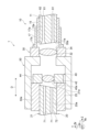
- Fig. 1 is a schematic cross-sectional view along the optical axis direction of an optical connection structure according to one embodiment.
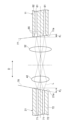
- Fig. 2 is a partial cross-sectional view of the optical connection structure.
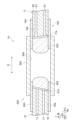
- Fig. 3 is a cross-sectional view of a multi-core fiber.
- the optical connection structure 1 has a configuration for optically coupling, for example, a pair of multi-core fibers.
- the optical connection structure 1 includes a first optical fiber unit 10, a second optical fiber unit 20, a first lens unit 30, a second lens unit 40, and a cylindrical member 50.
- the first optical fiber unit 10 includes a first MCF 11, a ferrule 15, and a sleeve 17.
- the second optical fiber unit 20 includes a second MCF 21 and a ferrule 25.
- the first MCF 11 corresponds to the first multi-core fiber
- the second MCF 21 corresponds to the second multi-core fiber.
- the ferrule 15 holds the first MCF 11.
- the ferrule 15 has a receiving hole 15a.
- the ferrule 15 receives a portion of the first MCF 11 inside the receiving hole 15a.
- the sleeve 17 holds the ferrule 15.
- the sleeve 17 receives at least a portion of the ferrule 15 inside the receiving hole 17a.
- the sleeve 17 has a flange portion 17b at one end in the axial direction.
- the flange portion 17b corresponds to the portion of the first optical fiber unit 10 that is fixed to the first lens unit 30.
- the ferrule 25 holds the second MCF 21.
- the ferrule 25 has a receiving hole 25a.
- the ferrule 25 receives a portion of the second MCF 21 inside the receiving hole 25a.
- the first lens unit 30 includes a first lens 32 and a cylindrical first lens holding member 34 that surrounds and holds the first lens 32.
- the second lens unit 40 includes a second lens 42 and a cylindrical second lens holding member 44 that surrounds and holds the second lens 42.
- the cylindrical member 50 has a receiving hole 50a.
- the cylindrical member 50 receives the second lens holding member 44 and at least a part of the ferrule 25 in the receiving hole 50a.
- the cylindrical member 50 and the ferrule 25 are fixed by an adhesive. If the cylindrical member 50 and the ferrule 25 are both made of metal, they can also be fixed by welding. The ferrule 25 can be fixed by pressing into the cylindrical member 50.
- the first lens holding member 34, the second lens holding member 44, and the cylindrical member 50 each have an opening.
- the first lens holding member 34, the second lens holding member 44, and the cylindrical member 50 each form two openings arranged in a straight line.
- the adhesive is, for example, a thermosetting adhesive or an ultraviolet (UV) curing adhesive.
- the first optical fiber unit 10 is fixed to the end of the tubular member 50 via the first lens holding member 34.
- the first optical fiber unit 10 is fixed to the first lens holding member 34 by welding.
- the flange portion 17b is welded to the end of the first lens holding member 34 so that the opening of the sleeve 17 and the opening of the first lens holding member 34 are in communication.
- the first lens holding member 34 holds the first lens 32 on the inner surface 30a.
- the first lens holding member 34 is connected to the end of the cylindrical member 50 so that the opening of the first lens holding member 34 communicates with the opening of the cylindrical member 50.
- the first lens holding member 34 is fixed to the cylindrical member 50 by welding.
- the second lens holding member 44 holds the second lens 42 on the inner surface 40a.
- the second lens holding member 44 is connected to the end of the ferrule 25 and is housed inside the cylindrical member 50.
- the second lens holding member 44 is fixed to the ferrule 25 by welding.
- welding is performed by irradiating a YAG laser.
- the above fixing may be performed by, for example, an adhesive.
- the first lens unit 30 and the ferrule 15 are aligned with respect to the integrated second optical fiber unit 20 and the cylindrical member 50. At this time, the first lens unit 30 is aligned in each of the X direction and the Y direction. The ferrule 15 is aligned in each of the X direction, the Y direction, the Z direction, and the ⁇ z direction. When the alignment is completed, the cylindrical member 50 and the first lens unit 30 are fixed by welding. After that, the ferrule 15 is aligned again in each of the directions perpendicular to the optical axis direction D and around the optical axis direction, and then the ferrule 15 and the sleeve 17 are fixed by welding or adhesive.
- the ferrule 15 fixed to the sleeve 17 is aligned in each of the X direction, the Y direction, and the ⁇ z direction, and then fixed to the first lens unit 30 by welding.
- the welding is performed, for example, by irradiating a YAG laser.
- the above adhesive is, for example, a thermosetting adhesive or a UV-curing adhesive.
- light L passing through the first MCF 11 is incident on the second MCF 21, or light L passing through the second MCF 21 is incident on the first MCF 11.
- the light L is, for example, light having a wavelength in the 1.55 ( ⁇ m) band.
- the MFD of the first fiber core 61, the MFD of the second fiber core 71, the core pitch P1 of the first fiber core 61, and the core pitch P2 of the second fiber core 71 have the relationship of the following formula (2).
- the inventors of the present application have derived that if the MFD is adjusted so that the relationship of the above formula (2) is satisfied, the optical coupling loss is reduced. As a result, the optical coupling loss can be suppressed in the joining of a pair of optical fibers having different core pitches.
- each of the multiple first fiber cores 61 may include a portion in which the MFD gradually decreases continuously or in steps with increasing distance from the first MCF end face 11a. In this case, compared to a configuration in which the MFD changes suddenly, leakage of incident light into the first MCF 11 at the first MCF end face 11a can be further suppressed. The same effect is achieved with the optical connection structures 1A and 1B.
- the focal length of the first lens 32 and the second lens 42 may be 0.5 or more and 4.0 or less. In this case, the distance between the lenses is ensured, so ease of manufacturing can be ensured. The same effect is achieved with the optical connection structures 1A and 1B.
- the present invention is not limited to the above embodiments and can be applied to various embodiments.
- the configurations of the optical connection structures 1, 1A, and 1B may be combined.
- the configuration on the second MCF 21 side and the configuration on the first MCF 11 side may have different configurations from the examples shown by the optical connection structures 1, 1A, and 1B.
- the multiple lenses arranged between the second MCF 21 and the first MCF 11 may be a combination of two or more lenses selected from a biconvex aspheric lens, a C lens, and a GRIN lens.
- the lenses located at both ends correspond to the first lens and the second lens.
- the number of first fiber cores 61 and the number of second fiber cores 71 are four each.
- the number of fiber cores is not limited to this.
- the number of first fiber cores 61 and the number of second fiber cores 71 may be seven each.
- the number of first fiber cores 61 and the number of second fiber cores 71 may be different from each other.
- the parts described as being connected by welding may be connected by adhesive. Also, the parts described as being connected by adhesive may be connected by welding.
Landscapes
- Physics & Mathematics (AREA)
- General Physics & Mathematics (AREA)
- Optics & Photonics (AREA)
- Optical Couplings Of Light Guides (AREA)
Abstract
Selon la présente invention, dans cette structure de connexion optique, la formule suivante est satisfaite. Concernant au moins une première âme de fibre (61) parmi une pluralité de premières âmes de fibre (61), le diamètre de champ de mode au niveau d'une première surface d'extrémité MCF (11a) est "D1". Concernant une seconde âme de fibre (71) correspondant à l'au moins une première âme de fibre (61) parmi une pluralité de secondes âmes de fibre (71), le diamètre de champ de mode au niveau d'une seconde surface d'extrémité MCF (21a) est "D2". Le pas d'âme de la pluralité de premières âmes de fibre (61) au niveau de la première surface d'extrémité MCF (11a) est "P1". Le pas d'âme de la pluralité de secondes âmes de fibre (71) au niveau de la seconde surface d'extrémité MCF (21a) est "P2". (P1/P2)×0,8 ≤ D1/D2 ≤ (P1/P2)×1,2
Applications Claiming Priority (2)
| Application Number | Priority Date | Filing Date | Title |
|---|---|---|---|
| JP2023099171 | 2023-06-16 | ||
| JP2023-099171 | 2023-06-16 |
Publications (1)
| Publication Number | Publication Date |
|---|---|
| WO2024257728A1 true WO2024257728A1 (fr) | 2024-12-19 |
Family
ID=93852004
Family Applications (1)
| Application Number | Title | Priority Date | Filing Date |
|---|---|---|---|
| PCT/JP2024/021061 Ceased WO2024257728A1 (fr) | 2023-06-16 | 2024-06-10 | Structure de connexion optique |
Country Status (1)
| Country | Link |
|---|---|
| WO (1) | WO2024257728A1 (fr) |
Citations (5)
| Publication number | Priority date | Publication date | Assignee | Title |
|---|---|---|---|---|
| CN104536100A (zh) * | 2014-12-15 | 2015-04-22 | 哈尔滨工程大学 | 一种基于梯度折射率透镜的多芯光纤连接器 |
| US20180188457A1 (en) * | 2016-12-30 | 2018-07-05 | Luxnet Corporation | Optical communication module configured for enhancing optical coupling efficiency |
| JP2020144186A (ja) * | 2019-03-05 | 2020-09-10 | 住友電気工業株式会社 | 光接続構造 |
| WO2022004220A1 (fr) * | 2020-06-29 | 2022-01-06 | 住友電気工業株式会社 | Structure de connexion de fibre optique |
| WO2022019019A1 (fr) * | 2020-07-22 | 2022-01-27 | 住友電気工業株式会社 | Module de fibre à âmes multiples et amplificateur de fibre à âmes multiples |
-
2024
- 2024-06-10 WO PCT/JP2024/021061 patent/WO2024257728A1/fr not_active Ceased
Patent Citations (5)
| Publication number | Priority date | Publication date | Assignee | Title |
|---|---|---|---|---|
| CN104536100A (zh) * | 2014-12-15 | 2015-04-22 | 哈尔滨工程大学 | 一种基于梯度折射率透镜的多芯光纤连接器 |
| US20180188457A1 (en) * | 2016-12-30 | 2018-07-05 | Luxnet Corporation | Optical communication module configured for enhancing optical coupling efficiency |
| JP2020144186A (ja) * | 2019-03-05 | 2020-09-10 | 住友電気工業株式会社 | 光接続構造 |
| WO2022004220A1 (fr) * | 2020-06-29 | 2022-01-06 | 住友電気工業株式会社 | Structure de connexion de fibre optique |
| WO2022019019A1 (fr) * | 2020-07-22 | 2022-01-27 | 住友電気工業株式会社 | Module de fibre à âmes multiples et amplificateur de fibre à âmes multiples |
Similar Documents
| Publication | Publication Date | Title |
|---|---|---|
| JP7658374B2 (ja) | 光ファイバ接続構造 | |
| US5768458A (en) | Optical coupling device with ball lens and method for manufacturing the same | |
| US6904197B2 (en) | Beam bending apparatus and method of manufacture | |
| US8503840B2 (en) | Optical-fiber array method and apparatus | |
| US6963682B2 (en) | Beam altering fiber lens device and method of manufacture | |
| US7068883B2 (en) | Symmetric, bi-aspheric lens for use in optical fiber collimator assemblies | |
| US7474822B2 (en) | Optical fiber collimator | |
| US6477301B1 (en) | Micro-optic coupler incorporating a tapered fiber | |
| US6909557B2 (en) | Optical coupling system and optical device using the same | |
| US7016574B2 (en) | Optical collimator structure | |
| WO2024257728A1 (fr) | Structure de connexion optique | |
| WO2024257727A1 (fr) | Structure de connexion optique | |
| JP2010026175A (ja) | 光ファイバコリメータアレイ | |
| JPH07281054A (ja) | 光ファイバー端末 | |
| US6807337B2 (en) | Optical device | |
| WO2025127041A1 (fr) | Structure de connexion optique et procédé de fabrication de structure de connexion optique | |
| JP2005266217A (ja) | ファイバコリメータ | |
| WO2025009508A1 (fr) | Structure de connexion optique et procédé de fabrication de structure de connexion optique | |
| CN116990908A (zh) | 基于自聚焦光纤式反射镜的多芯光纤芯间交换耦合器 | |
| JP2024129214A (ja) | 光ファイバ接続構造 | |
| JPWO2024257727A5 (fr) | ||
| CN113050227A (zh) | 一种光纤准直器 | |
| JPH0534545A (ja) | 光フアイバ結合器 | |
| JPH06130244A (ja) | 多チャネル光デバイス及びその製造方法 | |
| JP2004126095A (ja) | 2芯ファイバコリメータおよび光結合モジュール |
Legal Events
| Date | Code | Title | Description |
|---|---|---|---|
| 121 | Ep: the epo has been informed by wipo that ep was designated in this application |
Ref document number: 24823344 Country of ref document: EP Kind code of ref document: A1 |
|
| NENP | Non-entry into the national phase |
Ref country code: DE |