WO2024257727A1 - Structure de connexion optique - Google Patents
Structure de connexion optique Download PDFInfo
- Publication number
- WO2024257727A1 WO2024257727A1 PCT/JP2024/021060 JP2024021060W WO2024257727A1 WO 2024257727 A1 WO2024257727 A1 WO 2024257727A1 JP 2024021060 W JP2024021060 W JP 2024021060W WO 2024257727 A1 WO2024257727 A1 WO 2024257727A1
- Authority
- WO
- WIPO (PCT)
- Prior art keywords
- face
- fiber
- lens
- fiber cores
- core
- Prior art date
- Legal status (The legal status is an assumption and is not a legal conclusion. Google has not performed a legal analysis and makes no representation as to the accuracy of the status listed.)
- Ceased
Links
Images


Classifications
-
- G—PHYSICS
- G02—OPTICS
- G02B—OPTICAL ELEMENTS, SYSTEMS OR APPARATUS
- G02B6/00—Light guides; Structural details of arrangements comprising light guides and other optical elements, e.g. couplings
- G02B6/02—Optical fibres with cladding with or without a coating
-
- G—PHYSICS
- G02—OPTICS
- G02B—OPTICAL ELEMENTS, SYSTEMS OR APPARATUS
- G02B6/00—Light guides; Structural details of arrangements comprising light guides and other optical elements, e.g. couplings
- G02B6/24—Coupling light guides
- G02B6/26—Optical coupling means
- G02B6/32—Optical coupling means having lens focusing means positioned between opposed fibre ends
Definitions
- Patent Document 1 discloses an optical connection structure.
- the optical connection structure includes a multi-core fiber (hereinafter also referred to as "MCF") and a fiber bundle including multiple single-core fibers (hereinafter also referred to as "SCF").
- MCF multi-core fiber
- SCF single-core fibers
- An optical connection structure includes a first multicore fiber, a second multicore fiber, a fiber bundle, a first lens, and a second lens.
- the first multicore fiber includes a plurality of first fiber cores.
- the first multicore fiber has a first end face from which the plurality of first fiber cores are exposed.
- the second multicore fiber includes a plurality of second fiber cores.
- the second multicore fiber has a second end face from which the plurality of second fiber cores are exposed and a third end face from which the plurality of second fiber cores are exposed.
- the third end face is located on the opposite side to the second end face.
- Each of the plurality of second fiber cores is optically coupled to a corresponding first fiber core among the plurality of first fiber cores.
- the fiber bundle includes a plurality of single-core fibers each including a third fiber core.
- the fiber bundle has a fourth end face from which the third fiber core is exposed.
- the exposed surface of each of the plurality of second fiber cores at the second end face and the exposed surface of each of the plurality of first fiber cores at the first end face are optically coupled to each other.
- the exposed surfaces of the third fiber cores at the fourth end face and the exposed surfaces of the second fiber cores at the third end face are optically coupled to each other.
- the mode field diameter (MFD) of each of the second fiber cores at the third end face is smaller than the mode field diameter of the first fiber core corresponding to the second fiber core among the mode field diameters of the first fiber cores at the first end face.
- the core pitch of the third fiber cores at the fourth end face is larger than the core pitch of the second fiber cores at the third end face.
- the first lens and the second lens are arranged in order from the third end face to the fourth end face between the third end face and the fourth end face.
- the shape of the arrangement of the second fiber cores at the third end face and the shape of the arrangement of the third fiber cores at the fourth end face are similar to each other.
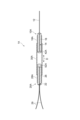
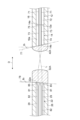
- FIG. 1 is a cross-sectional view taken along the optical axis direction of an optical connection structure according to an embodiment.
- FIG. 2 is a partially enlarged view of the optical connection structure.
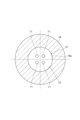
- FIG. 3 is a cross-sectional view of the first multi-core fiber in a direction perpendicular to the optical axis direction.
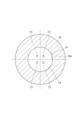
- FIG. 4 is a cross-sectional view of the second multi-core fiber in a direction perpendicular to the optical axis direction.
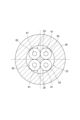
- FIG. 5 is a cross-sectional view of the fiber bundle in a direction perpendicular to the optical axis direction.
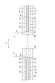
- FIG. 6 is a cross-sectional view taken along the optical axis direction of an optical connection structure according to a modified example of this embodiment.
- FIG. 7 is a partial enlarged view of an optical connection structure according to a modified example of this embodiment.
- FIG. 8 is a partial enlarged view of an optical connection structure according to a modified example of this embodiment.
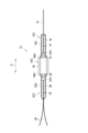
- FIG. 9 is a cross-sectional view taken along the optical axis direction of an optical connection structure in a modified example of this embodiment.
- the core pitch of the fiber bundle may be larger than the core pitch of the MCF.
- the core pitch means the distance between the fiber cores.
- the MCF is a coupled multicore fiber in which the modes of propagating light are randomly coupled between the fiber cores, the optical power per fiber core is reduced, but the core pitch of the MCF is very small, and it is difficult to fabricate a fiber bundle to match that pitch.
- a fiber bundle and an MCF which have different core pitches, are optically coupled via a tapered component.
- the tapered component converts the core pitch between the fiber bundle and the MCF.
- An optical connection structure includes a first multicore fiber, a second multicore fiber, a fiber bundle, a first lens, and a second lens.
- the first multicore fiber includes a plurality of first fiber cores.
- the first multicore fiber has a first end face from which the plurality of first fiber cores are exposed.
- the second multicore fiber includes a plurality of second fiber cores.
- the second multicore fiber has a second end face from which the plurality of second fiber cores are exposed and a third end face from which the plurality of second fiber cores are exposed.
- the third end face is located on the opposite side to the second end face.
- Each of the plurality of second fiber cores is optically coupled to a corresponding first fiber core among the plurality of first fiber cores.
- the fiber bundle includes a plurality of single-core fibers each including a third fiber core.
- the fiber bundle has a fourth end face from which the third fiber core is exposed.
- the exposed surface of each of the plurality of second fiber cores at the second end face and the exposed surface of each of the plurality of first fiber cores at the first end face are optically coupled to each other.
- the exposed surfaces of the third fiber cores at the fourth end face and the exposed surfaces of the second fiber cores at the third end face are optically coupled to each other.
- the mode field diameter of each of the second fiber cores at the third end face is smaller than the mode field diameter of the first fiber core corresponding to the second fiber core among the mode field diameters of the first fiber cores at the first end face.
- the core pitch of the third fiber cores at the fourth end face is larger than the core pitch of the second fiber cores at the third end face.
- the first lens and the second lens are arranged in order from the third end face to the fourth end face between the third end face and the 34th face.
- the shape of the arrangement of the second fiber cores at the third end face and the shape of the arrangement of the third fiber cores at the fourth end face are similar to each other.
- a second multicore fiber is provided that is optically coupled to the first multicore fiber.
- the mode field diameter of each of the multiple second fiber cores at the third end face is smaller than the mode field diameter of the first fiber core corresponding to the second fiber core among the multiple first fiber cores at the first end face.
- a first lens and a second lens are arranged between the second multicore fiber and the fiber bundle, and the second multicore fiber and the fiber bundle are optically coupled. In this case, optical coupling is performed via the first lens and the second lens, improving ease of manufacture.
- the focal length of the first lens is "f1".
- the focal length of the second lens is "f2".
- the core pitch of the multiple second fiber cores at the third end face is "P1".
- the core pitch of the multiple third fiber cores at the fourth end face is "P2”.
- the mode field diameter at the third end face for at least one second fiber core among the multiple second fiber cores is "D1”.
- the mode field diameter at the fourth end face for a third fiber core corresponding to at least one second fiber core among the multiple third fiber cores is "D2".
- the relationship consisting of the following formula may be satisfied.
- leakage of incident light into the fiber bundle can be further suppressed, and optical loss in the optical fiber can be further suppressed.
- the mode field diameter of each of the multiple third fiber cores at the fourth end face may be larger than the mode field diameter of the second fiber core corresponding to the third fiber core among the multiple second fiber cores at the third end face.
- the mode field diameter is converted along with the core pitch between the fiber bundle and the second multicore fiber by the first lens and the second lens, leakage of incident light into the fiber bundle can be suppressed. Therefore, optical loss in the optical fiber can be suppressed.
- the mode field diameter at the fourth end face may be larger than the mode field diameter at a position a predetermined distance away from the fourth end face. In this case, while an existing fiber bundle is used, leakage of incident light from the second multicore fiber to the fiber bundle at the fourth end face can be further suppressed.
- each of the multiple third fiber cores may include a portion in which the mode field diameter decreases with increasing distance from the fourth end face. In this case, leakage of incident light into the fiber bundle at the fourth end face can be further suppressed compared to a configuration in which the mode field diameter changes abruptly.
- the mode field diameter at the second end face may be larger than the mode field diameter at the third end face.
- the mode field diameter of the first multicore fiber is converted in the second multicore fiber.
- each of the second fiber cores may include a portion in which the mode field diameter decreases with increasing distance from the second end face. In this case, leakage of incident light into the second multicore fiber at the second end face can be further suppressed compared to a configuration in which the mode field diameter changes abruptly.
- any of the optical connection structures described in (1) to (7) above may further include a ferrule.
- the ferrule may have a receiving hole that receives at least a portion of the first multicore fiber and the second multicore fiber therein.
- the first end face of the first multicore fiber and the second end face of the second multicore fiber may be abutted against each other.
- the ferrule may receive the first end face and the second end face in the receiving hole. In this case, the optical connection structure can be made smaller.
- any of the optical connection structures (1) to (8) above may further include a ferrule having a receiving hole for receiving at least a portion of the multiple single-core fibers therein.
- the optical connection structure can be made smaller and the arrangement of the multiple single-core fibers can be stabilized.
- the angle at which the third end face is inclined relative to the optical axis of the first lens may be greater than the angle at which the fourth end face is inclined relative to the optical axis of the second lens.
- the optical axis of each lens and the optical axis of each optical fiber can be kept nearly parallel to each other, improving the ease of assembly of the optical connection structure.
- reflections at each end face can be reduced, improving the coupling efficiency between optical fibers.
- the fourth end face and the third end face may be arranged such that a V-shape is formed by a first imaginary plane including the third end face and a second imaginary plane including the fourth end face. In this case, the coupling efficiency between the optical fibers may be improved.
- the focal length of the first lens and the second lens may be 0.5 or more and 4.0 or less. In this case, the distance between the lenses is ensured, and therefore ease of manufacture can be ensured.
- the multiple first fiber cores may include coupled cores that are optically coupled to each other.
- the optical loss between the multicore fiber and the fiber bundle is easily suppressed. If a coupled multicore fiber is used, the optical power in each fiber core can be reduced, thereby suppressing degradation of the communication signal caused by optical power density.
- FIG. 1 is a cross-sectional view showing an optical connection structure according to one embodiment.
- FIG. 2 is a partially enlarged view of the optical connection structure shown in FIG. 1.
- FIG. 3 and FIG. 4 are cross-sectional views of a multi-core fiber.
- FIG. 5 is a cross-sectional view of a fiber bundle.
- the optical connection structure 1 constitutes, for example, a fan-in/fan-out device (Fan-In/Fan-Out: FIFO) of a lens-coupled multicore fiber.
- the optical connection structure 1 includes a first optical fiber unit 10, a second optical fiber unit 20, a metal tube 30, a first lens unit 40, and a second lens unit 50.
- the first optical fiber unit 10 includes an MCF 12, an MCF 14, a ferrule 16, and a sleeve 18.
- the second optical fiber unit 20 includes a fiber bundle 22 and a sleeve 28.
- the MCF 12 corresponds to the first multi-core fiber
- the MCF 14 corresponds to the second multi-core fiber.
- the ferrule 16 has a receiving hole 16a.
- the ferrule 16 receives at least a portion of the MCF 12 in the receiving hole 16a.
- the ferrule 16 receives a portion of the MCF 12 in the receiving hole 16a.
- the ferrule 16 receives at least a portion of the MCF 14 in the receiving hole 16a.
- the ferrule 16 receives the entire MCF 14 in the receiving hole 16a.
- the sleeve 18 has a flange portion 18b at one end in the axial direction.
- the flange portion 18b corresponds to a portion of the first optical fiber unit 10 that is fixed to the first lens unit 40.
- the fiber bundle 22 includes a ferrule 26 and a plurality of SCFs 29.
- the ferrule 26 has an accommodating hole 26a.
- the ferrule 26 accommodates at least some of the plurality of SCFs 29 inside the accommodating hole 26a.
- the sleeve 28 has a flange portion 28b at one end in the axial direction.
- the flange portion 28b corresponds to a portion of the second optical fiber unit 20 that is fixed to the second lens unit 50.
- the first lens unit 40 includes a first lens 42 and a cylindrical lens holding member 44 that surrounds and holds the first lens 42.
- the lens holding member 44 holds the first lens 42 on the inner surface 40a.
- the second lens unit 50 includes a second lens 52 and a cylindrical lens holding member 54 that surrounds and holds the second lens 52.
- the lens holding member 54 holds the second lens 52 on the inner surface 50a.
- the lens holding member 44, the lens holding member 54, and the metal tube 30 each have an opening.
- the lens holding member 44, the lens holding member 54, and the metal tube 30 each form two openings that are arranged on a straight line.
- the lens holding member 44 and the lens holding member 54 are each connected to an end of the metal tube 30 so that their respective openings communicate with the openings of the metal tube 30.
- the lens holding member 44 and the lens holding member 54 are each fixed to one of a pair of ends of the metal tube 30 that are located opposite each other.
- the lens holding member 44 and the lens holding member 54 are each fixed to the metal tube 30 by welding.
- the first optical fiber unit 10 is fixed to the end of the metal tube 30 via the lens holding member 44.
- the second optical fiber unit 20 is fixed to the end of the metal tube 30 via the lens holding member 54.
- the first optical fiber unit 10 is fixed to the lens holding member 44 by welding.
- the second optical fiber unit 20 is fixed to the lens holding member 54 by welding.
- the flange portion 18b is welded to the end of the lens holding member 44 so that the opening of the sleeve 18 and the opening of the lens holding member 44 are in communication.
- the flange portion 28b is welded to the end of the lens holding member 54 so that the opening of the sleeve 28 and the opening of the lens holding member 54 are in communication.
- the second lens unit 50 and the ferrule 26 are aligned with respect to the integrated first optical fiber unit 10 and metal tube 30. At this time, the second lens unit 50 is aligned in a direction perpendicular to the optical axis direction D. The ferrule 26 is aligned in both a direction perpendicular to the optical axis direction D and a direction around the optical axis direction. Once the alignment is complete, the metal tube 30 and the second lens unit 50 are fixed by welding. After that, the ferrule 26 is again aligned in both a direction perpendicular to the optical axis direction D and a direction around the optical axis direction, and the ferrule 26 and the sleeve 28 are fixed by welding.
- the ferrule 26 fixed to the sleeve 28 is aligned in both a direction perpendicular to the optical axis direction D and a direction around the optical axis direction, and then fixed to the second lens unit 50 by welding.
- the welding is performed, for example, by irradiating a YAG laser.
- the light L passing through the MCF 12 is separated into multiple SCFs 29 via the MCF 14, or the light L passing through each of the multiple SCFs 29 is coupled to one MCF 12 via one MCF 14, which is a fan-in/fan-out device.
- the light L is, for example, light having a wavelength in the 1.55 ( ⁇ m) band.
- the MCF 12, MCF 14, first lens 42, second lens 52, and fiber bundle 22 are arranged in this order along the optical axis direction D.
- the optical axis direction D is the extension direction of the MCF 14.
- the MCF 12 and each SCF 29 are optically coupled (spatially coupled) via space, the first lens 42, the second lens 52, and the MCF 14.
- the MCF 12 includes a plurality of fiber cores 71 and a cladding 72.
- the MCF 12 has an end face 12a. At the end face 12a, a plurality of fiber cores 71 are exposed.
- the end face 12a faces the first lens 42.
- the end face 12a is flat and parallel to a plane perpendicular to the optical axis direction D.
- the normal to the end face 12a is perpendicular to the optical axis direction D.
- the plurality of fiber cores 71 include coupled cores that are optically coupled to each other.
- the MCF 12 is, for example, a coupled multicore fiber.
- the MCF 14 includes a plurality of fiber cores 73 and a cladding 74.
- the MCF 14 has end faces 14a and 14b.
- a plurality of fiber cores 73 are exposed at each of the end faces 14a and 14b.
- the plurality of fiber cores 73 extend in the optical axis direction D.
- Each of the plurality of fiber cores 73 is optically coupled to a corresponding one of the plurality of fiber cores 71.
- the relative refractive index difference between the plurality of fiber cores 73 and the cladding 74 is greater than the relative refractive index difference between the plurality of fiber cores 71 and the cladding 72.
- the MCF 14 is an MCF in which the fiber core 71 has a high ⁇ .
- the relative refractive index difference is 3% or more.
- End face 14a faces end face 12a. In the example shown in this embodiment, end face 14a abuts end face 12a.
- end face 12a and end face 14a are fusion-connected to each other.
- end face 14a is flat and parallel to a plane perpendicular to the optical axis direction D.
- End face 14a is perpendicular to the optical axis direction D.
- End face 14b is located on the opposite side of end face 14a.
- End face 14b faces the first lens 42.
- end face 14b is flat and inclined with respect to the optical axis direction D and the plane perpendicular to the optical axis direction D.
- End face 14b is inclined at an angle ⁇ 1 with respect to the plane perpendicular to the optical axis direction D.
- the fiber bundle 22 includes a plurality of SCFs 29.
- Each of the plurality of SCFs 29 includes a fiber core 81 and a clad 82.
- the diameter of the clad 82 is, for example, 125 ( ⁇ m).
- the diameter of the clad 82 may be another value, for example, 80 ( ⁇ m).
- the fiber core 71 corresponds to the first fiber core
- the fiber core 73 corresponds to the second fiber core
- the fiber core 81 corresponds to the third fiber core.
- the fiber bundle 22 has an end face 22a.
- a plurality of fiber cores 81 are exposed at the end face 22a.
- the end face 22a faces the second lens 52.
- the end face 22a is flat, for example, like the end face 22a, and is inclined with respect to the optical axis direction D and a plane perpendicular to the optical axis direction D.
- the end face 22a is inclined at an angle ⁇ 2 with respect to a plane perpendicular to the optical axis direction D.
- the end face 22a and the end face 14b are arranged so that a V-shape is formed by a first imaginary plane 77 including the end face 14b and a second imaginary plane 78 including the end face 22a.
- the end face 12a corresponds to the first end face
- the end face 14a corresponds to the second end face
- the end face 14b corresponds to the third end face
- the end face 22a corresponds to the fourth end face.
- “arranged to form a V-shape” means that the first normal vector of the first imaginary plane 77 including the end face 14b and the second normal vector of the second imaginary plane 78 including the end face 22a are on the same plane, and within the same plane, the optical axis direction component of the first normal vector and the optical axis direction component of the second normal vector are components that approach each other, and the directional component perpendicular to the optical axis direction of the first normal vector and the directional component perpendicular to the optical axis direction of the second normal vector are components that are in the same direction.
- the optical connection structure 1 may, for example, split the light L passing through each fiber core 71 of the MCF 12 toward each of the fiber cores 81 of the multiple SCFs 29, and transmit each of the split light L to an optical amplifier that amplifies the split light L.
- the optical connection structure 1 may also be used in an optical transmitter that transmits light L to each of the fiber cores 81 of the multiple SCFs 29, or an optical receiver that receives light L from each of the multiple SCFs 29.
- FIG. 3 is a cross-sectional view of the MCF 12 cut on a plane perpendicular to the optical axis direction D. As shown in FIG. 3, the MCF 12 is held, for example, by a ferrule 16.
- Four fiber cores 71 are arranged in the cross section of the MCF 12 cut on a plane perpendicular to the optical axis direction D. The four fiber cores 71 are arranged in a square lattice pattern.
- FIG. 4 is a cross-sectional view of MCF 14 cut on a plane perpendicular to the optical axis direction D.
- MCF 14 is held by, for example, ferrule 16.
- Four fiber cores 73 are arranged in the cross section of MCF 14 cut on a plane perpendicular to the optical axis direction D.
- the four fiber cores 73 are arranged in a square lattice pattern.
- Fiber core 71 is thicker than fiber cores 73 in the tapered portion 75 described below.
- FIG. 5 is a cross-sectional view of the fiber bundle 22 cut in a plane perpendicular to the optical axis direction D.
- a plurality of SCFs 29 are bundled in the ferrule 26.
- four SCFs 29 are filled in the ferrule 26.
- the four SCFs 29 are arranged in a square lattice pattern.
- the exposed surfaces of the multiple fiber cores 73 at end face 14a and the exposed surfaces of the multiple fiber cores 71 at end face 12a are optically coupled to each other.
- the exposed surfaces of the multiple fiber cores 81 at end face 22a and the exposed surfaces of the multiple fiber cores 73 at end face 14b are optically coupled to each other.
- the shape of the arrangement of the multiple fiber cores 73 on the end face 14b and the shape of the arrangement of the multiple fiber cores 81 on the end face 22a are similar to each other.
- the shape of the arrangement of the multiple fiber cores 73 when the end face 14b is orthogonally projected in the optical axis direction D and the shape of the arrangement of the multiple fiber cores 81 when the end face 22a is orthogonally projected in the optical axis direction D are similar to each other.
- the shape of the arrangement of the multiple fiber cores 73 of the MCF 14 and the shape of the arrangement of the multiple fiber cores 81 of the fiber bundle 22 are similar to each other.
- the shape of the arrangement of the multiple fiber cores 71 of the MCF 12 and the shape of the arrangement of the multiple fiber cores 81 of the fiber bundle 22 are similar to each other.
- the core pitch of the multiple fiber cores 81 at end face 22a is greater than the core pitch of the multiple fiber cores 73 at end face 14b.
- the core pitch of the multiple fiber cores 81 at end face 22a is greater than the core pitch of the multiple fiber cores 71 at end face 14b.
- the core pitch of the multiple fiber cores 73 at end face 14a is the same as the core pitch of the multiple fiber cores 71 at end face 12a.
- core pitch corresponds to the distance between the centers of the fiber cores in a cross section perpendicular to the optical axis direction D.
- “same” includes deviations within the range of manufacturing error.
- the MFD at end face 14a is greater than the MFD at end face 14b.
- MFD is the mode field diameter.
- the MFD at end face 14a is greater than the MFD at a position a predetermined distance away from end face 14a in the optical axis direction D.
- Each of the multiple fiber cores 73 includes a portion in which the MFD decreases with increasing distance from end face 14a in the optical axis direction.
- the multiple fiber cores 73 include a tapered portion 75 in which the MFD is formed into a tapered shape. End face 12a and end face 14a are abutted against each other.
- each of the multiple fiber cores 81 the MFD at the end face 22a is greater than the MFD at a position a predetermined distance away from the end face 22a in the optical axis direction D.
- Each of the multiple fiber cores 81 includes a portion in which the MFD decreases with increasing distance from the end face 22a in the optical axis direction D.
- the multiple fiber cores 81 include a tapered portion 85 in which the MFD is formed into a tapered shape.
- MCF14 and SCF29 may be, for example, TEC (Thermally Expanded Core) fibers, and the MFD may be formed in a shape that differs in parts by TEC processing.
- TEC Thermally Expanded Core
- the tapered shape portion described above may be formed by TEC processing.
- the MFD of each of the multiple fiber cores 73 at end face 14b is smaller than the MFD of the fiber core 71 corresponding to the fiber core 73 among the MFDs of the multiple fiber cores 71 at end face 12a.
- the MFD of each of the multiple fiber cores 73 at end face 14a is the same as the MFD of the fiber core 71 corresponding to the fiber core 73 among the MFDs of the multiple fiber cores 71 at end face 12a.
- the MFD of each of the multiple fiber cores 81 at end face 22a is larger than the MFD of the fiber core 73 corresponding to the fiber core 81 among the MFDs of the multiple fiber cores 73 at end face 14b.
- the ferrule 16 accommodates the end face 12a and the end face 14a in the accommodation hole 16a.
- the ferrule 26 has an accommodation hole 26a.
- the first lens 42 is interposed between the MCF 12 and the multiple SCFs 29.
- the second lens 52 is interposed between the multiple SCFs 29 and the first lens 42.
- the first lens 42 and the second lens 52 are arranged between the end face 22a and the end face 14b in the following order: end face 14b, first lens 42, second lens 52, end face 22a.
- the first lens 42 is disposed in a position facing the MCF 14 along the optical axis direction D.
- the second lens 52 is disposed in a position facing the fiber bundle 22 along the optical axis direction D.
- the first lens 42 and the second lens 52 focus the multiple light beams L emitted from each of the multiple fiber cores 73 of the MCF 14 on the opposite side of the MCF 14 from the first lens 42 and the second lens 52.
- the second lens 52 and the first lens 42 focus the light beams L, for example, on each fiber core 73 of the end face 22a.
- the first lens 42 and the second lens 52 are, for example, biconvex aspheric lenses. When the first lens 42 and the second lens 52 are aspheric lenses, the coupling loss of the light beams L can be reduced.
- the core pitch of the fiber core 71 of MCF12 is "P0"
- the core pitch of the fiber core 73 of MCF14 is "P1”
- the core pitch of the fiber core 81 of the fiber bundle 22 is "P2”.
- the focal length of the first lens 42 is “f1", and the focal length of the second lens 52 is “f2".
- the core pitch of the multiple fiber cores 73 at the end face 14b is "P1”
- the core pitch of the multiple fiber cores 81 at the end face 22a is "P2”
- the MFD of at least one fiber core 73 among the multiple fiber cores 73 at the end face 14b is "D1”
- the MFD of the fiber core 81 corresponding to at least one fiber core 73 among the multiple fiber cores 81 at the end face 22a is "D2”
- the relationships shown in the following formulas (1) and (2) are satisfied.
- the lens system between the end face 14b of the MCF 14 and the end face 22a of the fiber bundle 22 has a magnification of 6.25 times.
- "P0" is 20 ( ⁇ m)
- "P1” is 20 ( ⁇ m)
- "P2” is 125 ( ⁇ m).
- the cladding diameter of each of the fiber bundle 22, the MCF 12, and the MCF 14 is, for example, 125 ( ⁇ m).
- “D0" is 10 ( ⁇ m) for light with a wavelength of 1.55 ( ⁇ m)
- the MFD at the end face 14a is also the same.
- "D1" is 5 ( ⁇ m) for light with a wavelength of 1.55 ( ⁇ m)
- "D2" is 31 ( ⁇ m) for light with a wavelength of 1.55 ( ⁇ m).
- the core pitch is preferably 30 ( ⁇ m) or more. In this case, crosstalk between fiber cores is suppressed.
- the shortest distance between the center of the fiber core and the outer periphery of the cladding is preferably 37.5 ( ⁇ m) or more. For example, if the cladding diameter is 125 ( ⁇ m), the core pitch is preferably 50 ( ⁇ m) or less. In this case, by making the core pitch smaller, the distance between the fiber core and the outer periphery of the cladding is secured, and light leakage to the outside is suppressed.
- the focal length "f1" of the first lens 42 and the focal length "f2" of the second lens 52 are 0.5 (mm) or more and 4.0 (mm) or less. If the focal length is 0.5 (mm) or more, the distance between the lenses and the distance between the fiber and the lens are ensured, making manufacturing easy. If the focal length is 4.0 (mm) or less, the sensitivity to losses due to tilt angle misalignment of the fiber and lens is suppressed, and the device can be made more compact.
- the MFD at the end face 14b of each of the multiple fiber cores 73 corresponds to "D1”
- the MFD at the end face 22a of each of the multiple fiber cores 81 corresponds to "D2”
- the relationship shown in the above formulas (1) and (2) is satisfied.
- FIG. 6 is a cross-sectional view showing the optical connection structure in this modified example.
- Figure 7 is a partially enlarged view of the optical connection structure.
- This modified example is generally similar or the same as the example shown in the above-mentioned embodiment.
- This modified example differs from the example shown in the above-mentioned embodiment in that the first optical fiber unit 10A and the second optical fiber unit 20A each include a lens, and that the first optical fiber unit 10A and the second optical fiber unit 20A are held by the same cylindrical tube.
- the differences between this modified example and the example shown in the above-mentioned embodiment will be mainly described.
- the optical connection structure 1A includes a first optical fiber unit 10A, a second optical fiber unit 20A, and a tubular member 30A.
- the first optical fiber unit 10A includes an MCF 12, an MCF 14, a ferrule 16, a sleeve 18A, and a first lens 42A.
- the second optical fiber unit 20A includes a fiber bundle 22, a ferrule 26, a sleeve 28A, and a second lens 52A.
- the tubular member 30A connects the first optical fiber unit 10A and the second optical fiber unit 20A to each other.
- the tubular member 30A is, for example, a glass tube.
- the first lens 42A and the second lens 52A are, for example, C lenses.
- the first lens 42A and the second lens 52A have, for example, the same refractive index and focal length as the first lens 42 and the second lens 52 described above, respectively.
- the first lens 42A is a rod lens that has a spherical surface on the second lens 52A side, a flat surface on the MCF 14 side, and the same outer diameter as the ferrule 16.
- the second lens 52A is a rod lens that has a spherical surface on the first lens 42A side, a flat surface on the fiber bundle 22 side, and the same outer diameter as the ferrule 26.
- a first lens 42B and a second lens 52B may be used instead of the first lens 42A and the second lens 52A.
- the first lens 42B and the second lens 52B are GRIN lenses.
- the first lens 42B and the second lens 52B have, for example, the same focal lengths as the first lens 42 and the second lens 52 described above, respectively.
- the first lens 42A has the same outer diameter as the ferrule 16.
- the second lens 52A has the same outer diameter as the ferrule 26.
- the first lens 42A is exposed from one side of the sleeve 18A, and the ferrule 16 holding the MCF 12 is exposed from the other side of the sleeve 18A.
- the MCF 12 extends from the ferrule 16 on the side opposite the first lens 42A and the cylindrical member 30A.
- the second lens 52A is exposed from one side of the sleeve 28A, and the ferrule 26 holding the MCF 14 is exposed from the other side of the sleeve 28A.
- the SCF 29 extends from the ferrule 26 on the side opposite the second lens 52A and the cylindrical member 30A.
- the MCF 14 extends from the ferrule 26 to the opposite side of the first lens 42A and the cylindrical member 30A.
- the first lens 42A is fixed to the end face 14b of the MCF 14.
- the second lens 52A is fixed to the end face 22a of the fiber bundle 22.
- the sleeve 18A and the sleeve 28A are fixed to the cylindrical member 30A with an adhesive.
- the above adhesive is, for example, a UV-curing adhesive.
- the first optical fiber unit 10A is inserted into the cylindrical member 30A from one side and is held at one end of the cylindrical member 30A.
- the second optical fiber unit 20A is inserted into the cylindrical member 30A from the other side and is held at the other end of the cylindrical member 30A.
- the first optical fiber unit 10A is fixed to the cylindrical member 30A with an adhesive after the second optical fiber unit 20A has been aligned.
- the above adhesive is, for example, a UV-curable adhesive.
- the above alignment is performed in six directions: X direction, Y direction, Z direction, ⁇ x direction, ⁇ y direction, and ⁇ z direction.
- the Z direction is the optical axis direction D
- the X direction and Y direction are directions perpendicular to the Z direction.
- the ⁇ x direction, ⁇ y direction, and ⁇ z direction indicate the direction around the X axis, the direction around the Y axis, and the direction around the Z axis, respectively.
- FIG. 9 is a cross-sectional view showing an optical connection structure in this modified example.
- This modified example is generally similar or the same as the example shown in the embodiment described above and the modified example shown in FIG. 6.
- This modified example differs from the example shown in the embodiment described above and the modified example described above in that it is provided with a sleeve having a different shape from the sleeves 18, 28 of the optical connection structures 1, 1A.
- the differences from the example shown in the embodiment described above and the modified example shown in FIG. 6 will be mainly described.
- the optical connection structure 1C includes a first optical fiber unit 10C, a second optical fiber unit 20C, and a metal tube 30C.
- the first optical fiber unit 10C includes an MCF 12, an MCF 14, a ferrule 16, a sleeve 18C, and a first lens 42A.
- the second optical fiber unit 20C includes a fiber bundle 22, a ferrule 26, a sleeve 28C, and a second lens 52A.
- the sleeve 18C has an insertion portion 91 that fits into the metal tube 30C, where the outer diameter is reduced and the inner surface protrudes radially inward of the sleeve 18C.
- the sleeve 28C also has an insertion portion 92 similar to the insertion portion 91.
- the metal tube 30C has a cylindrical main body portion 95 and a pair of annular inserted portions 96a, 96b connected to the main body portion 95.
- the main body portion 95 and the pair of inserted portions 96a, 96b each have two openings arranged in a straight line.
- the pair of inserted parts 96a, 96b are each connected to an end of the metal tube 30C so that their openings communicate with the openings of the metal tube 30C.
- the pair of inserted parts 96a, 96b are each fixed to the ends of the pair of ends of the metal tube 30C that are located opposite each other.
- the pair of inserted parts 96a, 96b are each fixed to the metal tube 30C by welding.
- the first optical fiber unit 10C is fixed to the end of the metal tube 30C via the inserted portion 96a.
- the second optical fiber unit 20C is fixed to the end of the metal tube 30C via the inserted portion 96b.
- One of the first optical fiber unit 10C and the second optical fiber unit 20C is fixed to the main body 95 by welding after the inserted portions 96a, 96b are aligned in the X direction, Y direction, Z direction, ⁇ x direction, ⁇ y direction, and ⁇ z direction, respectively.
- the welding is performed, for example, by irradiation with a YAG laser.
- an MCF 14 that is optically coupled to the MCF 12 is provided.
- the MFD of each of the multiple fiber cores 73 at the end face 14a is smaller than the MFD of the fiber core 71 corresponding to the fiber core 73 among the MFDs of the multiple fiber cores 71 at the end face 12a.
- a first lens 42 and a second lens 52 are arranged between the MCF 14 and the fiber bundle 22, and the MCF 14 and the fiber bundle 22 are optically coupled.
- the optical coupling is performed via the first lens 42 and the second lens 52, which improves the ease of manufacturing.
- the MFD of the MCF 12 is changed by the MCF 14, the optical loss of the optical fiber can also be suppressed. The same effects are achieved for the optical connection structures 1A and 1C.
- the focal length of the first lens 42 is “f1".
- the focal length of the second lens 52 is “f2".
- the core pitch of the multiple fiber cores 73 at the end face 14b is "P1".
- the core pitch of the multiple fiber cores 81 at the end face 22a is "P2”.
- the MFD of at least one fiber core 73 among the multiple fiber cores 73 at the end face 14b is "D1”.
- the MFD of the fiber core 81 corresponding to at least one fiber core 73 among the multiple fiber cores 73 at the end face 22a is "D2".
- the relationship consisting of formulas (1) and (2) may be satisfied.
- the MFD of each of the multiple fiber cores 81 at the end face 22a is greater than the MFD of the fiber core 73 corresponding to the fiber core 81 among the multiple fiber cores 73 at the end face 14b.
- the MFD is converted along with the core pitch between the fiber bundle 22 and the MCF 14 by the first lens 42 and the second lens 52, leakage of incident light into the fiber bundle 22 can be suppressed. Therefore, optical loss in the optical fiber can be suppressed.
- the same effect is achieved for the optical connection structures 1A and 1C.
- the MFD at the end face 22a of each of the multiple fiber cores 81 is greater than the MFD at a position a predetermined distance away from the end face 22a.
- leakage of incident light from the MCF 14 to the fiber bundle 22 at the end face 22a can be further suppressed.
- the same effect is achieved with the optical connection structures 1A and 1C.
- each of the multiple fiber cores 81 includes a portion in which the MFD decreases with increasing distance from the end face 22a. In this case, compared to a configuration in which the MFD changes rapidly, leakage of incident light into the fiber bundle 22 at the end face 22a can be further suppressed. The same effect is achieved with the optical connection structures 1A and 1C.
- the MFD at end face 14b of each of the multiple fiber cores 73 is greater than the MFD at end face 14a.
- the MFD of MCF 12 is converted in MCF 14. The same effect is achieved for optical connection structures 1A and 1C.
- each of the multiple fiber cores 73 includes a portion in which the MFD decreases with increasing distance from the end face 14a. In this case, compared to a configuration in which the MFD changes rapidly, leakage of incident light into the fiber bundle 22 at the end face 14a can be further suppressed. The same effect is achieved with the optical connection structures 1A and 1C.
- the optical connection structure 1 further includes a ferrule 16.
- the ferrule 16 has a receiving hole 16a that receives at least a portion of the MCF 12 and the MCF 14 therein.
- the end face 12a of the MCF 12 and the end face 14a of the MCF 14 may be abutted against each other.
- the ferrule 16 receives the end face 12a and the end face 14a in the receiving hole 16a.
- the optical connection structure 1 can be made smaller. The same effect is achieved for the optical connection structures 1A and 1C.
- the optical connection structure 1 includes a ferrule 26 having a receiving hole 26a.
- the receiving hole 26a receives at least a portion of the multiple SCFs 29 therein.
- the optical connection structure 1 is made smaller and the arrangement of the multiple SCFs 29 is stabilized. The same effect is achieved with the optical connection structures 1A and 1C.
- the angle at which the end face 14b is inclined relative to the optical axis of the first lens 42 is greater than the angle at which the end face 22a is inclined relative to the optical axis of the second lens 52.
- the optical axes of the first lens 42 and the second lens 52 and the optical axes of the optical fibers can be kept nearly parallel to each other, improving the ease of assembly of the optical connection structure 1.
- the optical coupling loss of the optical fibers can be further suppressed.
- the refractive indexes are the same, the same material can be used. If the same material is used, the expansion coefficient according to the environmental temperature is also the same. The same effect is achieved for the optical connection structures 1A and 1C.
- the end faces 22a and 14b are arranged so that a V-shape is formed by a first imaginary plane 77 including the end face 14b and a second imaginary plane 78 including the end face 22a.
- the coupling efficiency between the optical fibers can be improved.
- the same effect is achieved with the optical connection structures 1A and 1C.
- the focal length of the first lens 42 and the second lens 52 is 0.5 or more and 4.0 or less. In this case, the distance between the lenses is ensured. Therefore, ease of manufacturing can be ensured. The same effect is achieved for the optical connection structures 1A and 1C.
- the multiple fiber cores 71 include coupled cores that are optically coupled to each other.
- the optical loss between the MCF and the fiber bundle is easily suppressed.
- the optical power in each fiber core can be reduced, suppressing degradation of the communication signal caused by optical power density. The same effect is achieved with the optical connection structures 1A and 1C.
- the core pitch is very narrow.
- the core pitch of the coupled multicore fiber is about 20 ( ⁇ m).
- a connection method in which the tip of the SCF of the fiber bundle 22 is thinned can be considered.
- the same core arrangement as that of the coupled multicore fiber is realized by bundling the thin-diameter processed fibers, and the fiber bundle and the coupled multicore fiber are physically in contact.
- a core pitch of 30 ( ⁇ m) or more is considered to be realistic from the viewpoint of mechanical strength and bending loss.
- the optical connection structures 1, 1A, and 1C a configuration in which optical loss is easily suppressed in this case can be realized.
- the present invention is not limited to the above embodiments and can be applied to various embodiments.
- the configurations of the optical connection structures 1, 1A, and 1C may be combined.
- the configuration of the fiber bundle side and the configuration of the MCF side may have different configurations from those of the examples shown by the optical connection structures 1, 1A, and 1C.
- the multiple lenses arranged between the fiber bundle 22 and the MCF 14 may be a combination of two or more lenses selected from a biconvex aspheric lens, a C lens, and a GRIN lens.
- the lenses located at both ends correspond to the first lens and the second lens.
- the number of fiber cores 71, 73, and 81 is four each.
- the number of fiber cores is not limited to this.
- the number of fiber cores 71, 73, and 81 may be seven each.
- the number of fiber cores 71, 73, and 81 may be different from each other.
- the parts described as being connected by welding may be connected by adhesive. Also, the parts described as being connected by adhesive may be connected by welding.
Landscapes
- Physics & Mathematics (AREA)
- General Physics & Mathematics (AREA)
- Optics & Photonics (AREA)
- Optical Couplings Of Light Guides (AREA)
Abstract
Selon la présente invention, le diamètre de champ de mode de chacune d'une pluralité de deuxièmes âmes de fibre (73) sur une troisième surface d'extrémité (14b) est inférieur au diamètre de champ de mode d'une première âme de fibre (71) correspondant à une deuxième âme de fibre (73), parmi les diamètres de champ de mode d'une pluralité des premières âmes de fibre (71) sur une première surface d'extrémité (12a). Le pas d'âme d'une pluralité de troisièmes âmes de fibre (81) sur une quatrième surface d'extrémité (22a) est supérieur au pas d'âme de la pluralité de deuxièmes âmes de fibre (73) sur la troisième surface d'extrémité (14b). Une première lentille (42) et une deuxième lentille (52) sont agencées dans l'ordre de la troisième surface d'extrémité (14b) à la quatrième surface d'extrémité (22a), entre la troisième surface d'extrémité (14b) et la quatrième surface d'extrémité (22a). La forme de l'agencement de la pluralité de deuxièmes âmes de fibre (73) sur la troisième surface d'extrémité (14b) et la forme de l'agencement de la pluralité de troisièmes âmes de fibre (81) sur la quatrième surface d'extrémité (22a) sont similaires les unes aux autres.
Priority Applications (2)
| Application Number | Priority Date | Filing Date | Title |
|---|---|---|---|
| CN202480038416.4A CN121263722A (zh) | 2023-06-14 | 2024-06-10 | 光连接结构体 |
| JP2025527914A JPWO2024257727A1 (fr) | 2023-06-14 | 2024-06-10 |
Applications Claiming Priority (2)
| Application Number | Priority Date | Filing Date | Title |
|---|---|---|---|
| JP2023097921 | 2023-06-14 | ||
| JP2023-097921 | 2023-06-14 |
Publications (1)
| Publication Number | Publication Date |
|---|---|
| WO2024257727A1 true WO2024257727A1 (fr) | 2024-12-19 |
Family
ID=93852008
Family Applications (1)
| Application Number | Title | Priority Date | Filing Date |
|---|---|---|---|
| PCT/JP2024/021060 Ceased WO2024257727A1 (fr) | 2023-06-14 | 2024-06-10 | Structure de connexion optique |
Country Status (3)
| Country | Link |
|---|---|
| JP (1) | JPWO2024257727A1 (fr) |
| CN (1) | CN121263722A (fr) |
| WO (1) | WO2024257727A1 (fr) |
Citations (6)
| Publication number | Priority date | Publication date | Assignee | Title |
|---|---|---|---|---|
| CN104536100A (zh) * | 2014-12-15 | 2015-04-22 | 哈尔滨工程大学 | 一种基于梯度折射率透镜的多芯光纤连接器 |
| US20180188457A1 (en) * | 2016-12-30 | 2018-07-05 | Luxnet Corporation | Optical communication module configured for enhancing optical coupling efficiency |
| WO2020080254A1 (fr) * | 2018-10-15 | 2020-04-23 | 住友電気工業株式会社 | Module optique et procédé de fabrication d'un module optique |
| JP2020144186A (ja) * | 2019-03-05 | 2020-09-10 | 住友電気工業株式会社 | 光接続構造 |
| WO2022004220A1 (fr) * | 2020-06-29 | 2022-01-06 | 住友電気工業株式会社 | Structure de connexion de fibre optique |
| WO2022019019A1 (fr) * | 2020-07-22 | 2022-01-27 | 住友電気工業株式会社 | Module de fibre à âmes multiples et amplificateur de fibre à âmes multiples |
-
2024
- 2024-06-10 WO PCT/JP2024/021060 patent/WO2024257727A1/fr not_active Ceased
- 2024-06-10 JP JP2025527914A patent/JPWO2024257727A1/ja active Pending
- 2024-06-10 CN CN202480038416.4A patent/CN121263722A/zh active Pending
Patent Citations (6)
| Publication number | Priority date | Publication date | Assignee | Title |
|---|---|---|---|---|
| CN104536100A (zh) * | 2014-12-15 | 2015-04-22 | 哈尔滨工程大学 | 一种基于梯度折射率透镜的多芯光纤连接器 |
| US20180188457A1 (en) * | 2016-12-30 | 2018-07-05 | Luxnet Corporation | Optical communication module configured for enhancing optical coupling efficiency |
| WO2020080254A1 (fr) * | 2018-10-15 | 2020-04-23 | 住友電気工業株式会社 | Module optique et procédé de fabrication d'un module optique |
| JP2020144186A (ja) * | 2019-03-05 | 2020-09-10 | 住友電気工業株式会社 | 光接続構造 |
| WO2022004220A1 (fr) * | 2020-06-29 | 2022-01-06 | 住友電気工業株式会社 | Structure de connexion de fibre optique |
| WO2022019019A1 (fr) * | 2020-07-22 | 2022-01-27 | 住友電気工業株式会社 | Module de fibre à âmes multiples et amplificateur de fibre à âmes multiples |
Also Published As
| Publication number | Publication date |
|---|---|
| JPWO2024257727A1 (fr) | 2024-12-19 |
| CN121263722A (zh) | 2026-01-02 |
Similar Documents
| Publication | Publication Date | Title |
|---|---|---|
| JP7658374B2 (ja) | 光ファイバ接続構造 | |
| US10234637B2 (en) | Expanded beam fiber optic connector, and cable assembly, and methods for manufacturing | |
| US7474822B2 (en) | Optical fiber collimator | |
| JP2004534271A (ja) | ハイブリッド型ファイバ拡大ビームコネクタ | |
| JPH08201644A (ja) | 定偏波光ファイバ用4心フェルールおよび前記フェルールを用いた光分岐結合器 | |
| WO2025209608A2 (fr) | Élément noyau de conversion, dispositif de conversion de champ de mode à double lentille et son procédé de fabrication | |
| JP3888942B2 (ja) | 光ファイバ部品 | |
| CN118330819A (zh) | 实芯光纤与空芯光纤的连接结构 | |
| WO2019044055A1 (fr) | Réseau de lentilles de type capillaire et composant composite de réseau de lentilles de type capillaire | |
| CN101535862A (zh) | 透镜组件、光学器件及光学器件的光轴调节方法 | |
| US20130272658A1 (en) | Multi-mode multi-fiber connection with expanded beam | |
| WO2024257727A1 (fr) | Structure de connexion optique | |
| CN217606137U (zh) | 一种光模块 | |
| CN118409389A (zh) | 光纤束、光连接结构以及光纤束的制造方法 | |
| WO2024257728A1 (fr) | Structure de connexion optique | |
| CN117388987A (zh) | 光纤束结构、光连接结构体及光纤束结构的制造方法 | |
| RU2849002C1 (ru) | Волоконно-оптический соединитель с расширенным пучком | |
| WO2025127041A1 (fr) | Structure de connexion optique et procédé de fabrication de structure de connexion optique | |
| US20250004204A1 (en) | System for coupling a multi-core optical fiber with at least one single-core optical fiber, and corresponding coupling method | |
| JPWO2024257727A5 (fr) | ||
| US20260110846A1 (en) | Lc connector for hollow-core optical fibers | |
| JP2020129063A (ja) | 光ファイバ、多芯光ファイバ、及び光コネクタ | |
| WO2025009508A1 (fr) | Structure de connexion optique et procédé de fabrication de structure de connexion optique | |
| JP2005202136A (ja) | 光学部材 | |
| JP2005266217A (ja) | ファイバコリメータ |
Legal Events
| Date | Code | Title | Description |
|---|---|---|---|
| 121 | Ep: the epo has been informed by wipo that ep was designated in this application |
Ref document number: 24823343 Country of ref document: EP Kind code of ref document: A1 |
|
| ENP | Entry into the national phase |
Ref document number: 2025527914 Country of ref document: JP Kind code of ref document: A |
|
| WWE | Wipo information: entry into national phase |
Ref document number: 2025527914 Country of ref document: JP |
|
| NENP | Non-entry into the national phase |
Ref country code: DE |