WO2024257729A1 - Connecteur - Google Patents
Connecteur Download PDFInfo
- Publication number
- WO2024257729A1 WO2024257729A1 PCT/JP2024/021065 JP2024021065W WO2024257729A1 WO 2024257729 A1 WO2024257729 A1 WO 2024257729A1 JP 2024021065 W JP2024021065 W JP 2024021065W WO 2024257729 A1 WO2024257729 A1 WO 2024257729A1
- Authority
- WO
- WIPO (PCT)
- Prior art keywords
- press
- fit
- conductor
- connector
- hole
- Prior art date
- Legal status (The legal status is an assumption and is not a legal conclusion. Google has not performed a legal analysis and makes no representation as to the accuracy of the status listed.)
- Ceased
Links
Images



Classifications
-
- H—ELECTRICITY
- H01—ELECTRIC ELEMENTS
- H01R—ELECTRICALLY-CONDUCTIVE CONNECTIONS; STRUCTURAL ASSOCIATIONS OF A PLURALITY OF MUTUALLY-INSULATED ELECTRICAL CONNECTING ELEMENTS; COUPLING DEVICES; CURRENT COLLECTORS
- H01R24/00—Two-part coupling devices, or either of their cooperating parts, characterised by their overall structure
- H01R24/38—Two-part coupling devices, or either of their cooperating parts, characterised by their overall structure having concentrically or coaxially arranged contacts
Definitions
- This disclosure relates to connectors.
- Patent Document 1 discloses a connector including a case having an accommodating hole, and a tubular conductor accommodated in the accommodating hole by press-fitting.
- the accommodating hole of the case has an entrance end which is one of both axial ends of the accommodating hole, and an exit end which is the other of both axial ends of the accommodating hole.
- the tubular conductor is inserted into the accommodating hole from the entrance end.
- the tubular conductor has a press-fit protrusion that protrudes to the outer periphery. The press-fit protrusion bites into the inner circumferential surface of the accommodating hole, thereby fixing the tubular conductor to the accommodating hole.
- the inventors have discovered that the longer the axial distance from the entrance end of the accommodating hole to the position of the press-fit protrusion (hereinafter referred to as the press-fit distance), the more stably the tubular conductor can be held in the accommodating hole. Furthermore, the inventors have considered how to minimize the increase in the amount of material used to form the case while still stably holding the tubular conductor in the accommodating hole.
- the objective of this disclosure is to provide a connector that ensures a sufficient press-fit distance and allows the tubular conductor to be stably held in the receiving hole while minimizing the increase in the amount of material used to form the case.
- the connector of the present disclosure is a connector comprising a case having an accommodating hole, and a tubular conductor accommodated in the accommodating hole by press-fitting, the accommodating hole having an entrance end which is one of both axial ends of the accommodating hole and an exit end which is the other of both axial ends of the accommodating hole, the tubular conductor being inserted into the accommodating hole from the entrance end, the tubular conductor having a press-fit protrusion protruding outward, the press-fit protrusion biting into the inner peripheral surface of the accommodating hole, thereby fixing the tubular conductor to the case, the accommodating hole having an extension extending from the exit end outward in the axial direction of the accommodating hole, the press-fit protrusion biting into the extension.
- the connector disclosed herein makes it possible to minimize the increase in the amount of material used to form the case while ensuring a sufficient press-fit distance to stably hold the tubular conductor in the receiving hole.
- FIG. 1 is an exploded perspective view of a connector according to an embodiment.
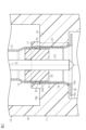
- FIG. 2 is a cross-sectional view of the connector in the same embodiment.
- FIG. 3 is a perspective view of the terminal unit in the same embodiment.
- FIG. 4 is a plan view of the connector in the same embodiment.
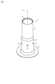
- FIG. 5 is a plan view of a connector in a modified example.
- FIG. 6 is a cross-sectional view of the connector in the same modified example.
- the connector of the present disclosure comprises: [1] A connector comprising a case having an accommodating hole and a tubular conductor accommodated in the accommodating hole by press-fitting, wherein the accommodating hole has an entrance end which is one of both axial ends of the accommodating hole and an exit end which is the other of both axial ends of the accommodating hole, the tubular conductor being inserted into the accommodating hole from the entrance end, the tubular conductor having a press-fit protrusion protruding outward, the press-fit protrusion biting into an inner circumferential surface of the accommodating hole thereby fixing the tubular conductor to the case, the accommodating hole having an extension extending from the exit end outward in the axial direction of the accommodating hole, and the press-fit protrusion biting into the extension.
- the press-fit protrusion of the tubular conductor bites into the extension extending from the exit end of the accommodating hole, making it possible to ensure a large press-fit distance from the entrance end of the accommodating hole to the position of the press-fit protrusion. Furthermore, by providing an extension in the accommodating hole, it is possible to ensure the press-fit distance while minimizing the increase in the volume of the case. Therefore, it is possible to ensure the press-fit distance and stably hold the tubular conductor in the accommodating hole while minimizing the increase in the amount of material used to form the case. Furthermore, by being able to ensure a large press-fit distance, there is less need to increase the number of press-fit protrusions. Therefore, it is possible to keep the number of press-fit protrusions small, and as a result, it is possible to obtain the desired communication performance in the tubular conductor.
- the press-fit protrusion may be provided in plurality on the cylindrical conductor, and the press-fit protrusions may be provided at the same positions as one another in the axial direction. According to this configuration, the cylindrical conductor can be more stably held in the accommodating hole by the multiple press-fit protrusions.
- the multiple press-fit protrusions may be provided at equal angular intervals in the circumferential direction. According to this configuration, the cylindrical conductor can be held in the receiving hole in a circumferentially balanced manner by the multiple press-fit protrusions provided at equal angular intervals in the circumferential direction.
- the extension portion may be annular and extend along the entire periphery of the receiving hole. According to this configuration, since the extension portion has an annular shape that follows the entire circumference of the receiving hole, it is possible to improve the rigidity of the extension portion, and thus it is possible to more stably hold the cylindrical conductor by the press-fit convex portion biting into the extension portion.
- the press-fit protrusion may be provided in multiple locations on the cylindrical conductor, the extension may be provided in multiple locations along the periphery of the receiving hole, and the multiple extensions may be provided at positions corresponding to each of the multiple press-fit protrusions.
- the cylindrical conductor can be more stably held in the accommodating hole by the multiple press-fit protrusions that bite into the multiple extending portions, respectively.
- the case may have a plurality of reinforcing ribs that individually reinforce the plurality of extensions.
- the reinforcing ribs can improve the rigidity of each extension. This makes it possible to more stably hold the tubular conductor by the press-fit protrusions biting into the extensions.
- the connector may include a terminal unit including an outer conductor as the tubular conductor, and the terminal unit may have a dielectric fixed inside the outer conductor and an inner conductor supported by the dielectric.
- the outer conductor constituting the terminal unit can be stably held in the receiving hole.
- Specific examples of the connector of the present disclosure will be described below with reference to the drawings. In each drawing, for convenience of explanation, some of the configuration may be exaggerated or simplified. In addition, the dimensional ratio of each part may differ in each drawing.
- the "cylindrical" used in the description of this specification includes not only those in which a peripheral wall is formed continuously around the entire circumference, but also those in which a plurality of parts are combined to form a cylindrical shape, and those having a notch in a part of the circumference such as a C-shape.
- the shape of the "cylindrical” includes a circle, an ellipse, and a polygon with sharp or rounded corners.
- the connector 10 of this embodiment shown in FIG. 1 is connected to, for example, an electrical device (not shown) mounted on a vehicle.
- An example of an electrical device to which the connector 10 is connected is an in-vehicle camera.
- the connector 10 includes a case 11 and a terminal unit 12 housed in the case 11 .
- the case 11 has a base 13, a fitting tube 14, and a receiving hole 15.
- the fitting tube 14 extends from the base 13 along the axis CL of the connector 10.
- the fitting tube 14 has, for example, a cylindrical shape centered on the axis CL of the connector 10. In the following description, the direction along the axis CL may be simply referred to as the "axial direction.”
- the fitting tube 14 is fitted into the connector portion of the electrical device.
- the fitting tube portion 14 has, for example, a holding portion 16 that holds the terminal unit 12 on the inner peripheral side of the fitting tube portion 14.
- the holding portion 16 extends from the inner peripheral surface of the fitting tube portion 14 to the inner peripheral side.
- the holding portion 16 has a first end face 16a and a second end face 16b, which are both axial end faces of the holding portion 16.
- the accommodation hole 15 is formed to penetrate the holding portion 16 along the axial direction.
- the accommodation hole 15 is a through hole that connects the inside of the fitting tube portion 14 and the inside of the base portion 13.
- the accommodation hole 15 is, for example, circular with the axis CL as the center.
- the accommodation hole 15 has an inlet end 15a which is one of both axial ends of the accommodation hole 15, and an outlet end 15b which is the other of both axial ends of the accommodation hole 15.
- the inlet end 15a of the accommodation hole 15 is provided on the first end surface 16a side of the holding portion 16.
- the outlet end 15b of the accommodation hole 15 is provided on the second end surface 16b side of the holding portion 16.
- the outlet end 15b is set, for example, on the same plane perpendicular to the axis CL with respect to the second end surface 16b of the holding portion 16.
- the accommodation hole 15 has an extension portion 17 that extends from the outlet end portion 15b outward in the axial direction of the accommodation hole 15.
- the extension portion 17 extends in the axial direction from the second end face 16b of the retaining portion 16 at a position corresponding to the periphery of the accommodation hole 15.
- the extension portion 17 has, for example, a continuous ring shape along the entire periphery of the accommodation hole 15.
- the extension portion 17 is formed so as to be continuous in the circumferential direction, thereby improving the rigidity of the extension portion 17. Note that, for example, a space is provided between the outer peripheral surface of the extension portion 17 and the inner peripheral surface of the fitting tube portion 14.
- Terminal unit 12 The terminal unit 12 is inserted into the receiving hole 15 along the axis CL from the inlet end 15a.
- the terminal unit 12 is connected to a terminal (not shown) of the electrical device.
- the terminal unit 12 has an outer conductor 21 as a cylindrical conductor, a dielectric 22, and an inner conductor 23.
- the outer conductor 21 has a cylindrical shape extending along the axis CL.
- the outer conductor 21 is made of, for example, a metal.
- the dielectric 22 is fixed to the inside of the outer conductor 21.
- the dielectric 22 is made of an insulator such as a synthetic resin.
- the inner conductor 23 has, for example, a columnar shape.
- the inner conductor 23 is made of, for example, a metal.
- the inner conductor 23 is fixed to the dielectric 22 in a manner that penetrates the center of the dielectric 22 in the axial direction.
- the outer conductor 21 is configured, for example, to electromagnetically shield the inner conductor 23.
- the outer conductor 21 has a tubular main body 31 extending along the axis CL and a flange 32 provided on the main body 31.
- the main body 31 is, for example, cylindrical with the axis CL as its center.
- the main body 31 has a tip 31a in the axial direction.
- the flange 32 extends, for example, from an axial base end of the main body 31 opposite the tip 31a to the outer periphery.
- the flange 32 faces, for example, a first end face 16a of the holding portion 16 in the axial direction.
- the outer conductor 21 has press-fit protrusions 33 protruding from the main body 31 to the outer periphery.
- the outer shape of the main body 31 including each press-fit protrusion 33 in the terminal unit 12 is illustrated by a two-dot chain line.
- a plurality of press-fit protrusions 33 are provided on the outer conductor 21.
- six press-fit protrusions 33 are provided on the main body 31 of the outer conductor 21.
- each of the plurality of press-fit protrusions 33 has the same shape as each other.
- the plurality of press-fit protrusions 33 are provided at equal angular intervals in the circumferential direction.
- the plurality of press-fit protrusions 33 are provided at the same positions as each other in the axial direction.
- each press-fit protrusion 33 is formed by protruding a part of the peripheral wall forming the main body 31 to the outer periphery by press working.
- the outer conductor 21 is accommodated in the accommodating hole 15 by press-fitting.
- the outer conductor 21 is inserted into the accommodating hole 15 from the entrance end 15a along the axis CL.
- each press-fit protrusion 33 bites into the inner circumferential surface of the extension portion 17 in the accommodating hole 15. This fixes the terminal unit 12 including the outer conductor 21 to the accommodating hole 15.
- the press-fit protrusion 33 bites into the extension 17 in the accommodating hole 15, thereby fixing the outer conductor 21 to the accommodating hole 15.
- This makes it possible to ensure a large press-fit distance D1, which is the axial distance from the inlet end 15a of the accommodating hole 15 to the position of the press-fit protrusion 33, and as a result, it becomes possible to stably hold the outer conductor 21 in the accommodating hole 15.
- the extension 17 is formed only at a position in the retaining portion 16 that corresponds to the periphery of the accommodating hole 15. This therefore makes it possible to suppress an increase in the volume of the case 11, i.e., an increase in the amount of material used to form the case 11, compared to a configuration in which the axial thickness of the entire retaining portion 16 is increased.
- the housing hole 15 of the case 11 has an extension 17 extending from the outlet end 15b to the outside in the axial direction of the housing hole 15.
- the press-fit convex portion 33 of the outer conductor 21 as a cylindrical conductor bites into the extension 17.
- the press-fit convex portion 33 of the outer conductor 21 bites into the extension 17 extending from the outlet end 15b of the housing hole 15, so that it is possible to secure a large press-fit distance D1 from the inlet end 15a of the housing hole 15 to the position of the press-fit convex portion 33.
- D1 the press-fit distance from the inlet end 15a of the housing hole 15 to the position of the press-fit convex portion 33.
- by providing the extension 17 in the housing hole 15 it is possible to secure the press-fit distance D1 while minimizing an increase in the volume of the case 11.
- a plurality of press-fit protrusions 33 are provided on the outer conductor 21.
- the plurality of press-fit protrusions 33 are provided at the same positions relative to one another in the axial direction. With this configuration, the plurality of press-fit protrusions 33 make it possible to more stably hold the outer conductor 21 in the receiving hole 15.
- the multiple press-fit protrusions 33 are arranged at equal angular intervals in the circumferential direction. With this configuration, the multiple press-fit protrusions 33 arranged at equal angular intervals in the circumferential direction make it possible to hold the outer conductor 21 in the receiving hole 15 in a balanced manner in the circumferential direction.
- the extension portion 17 is annular along the entire circumference of the receiving hole 15, which makes it possible to improve the rigidity of the extension portion 17. This makes it possible to more stably hold the outer conductor 21 by the press-fit protrusion 33 biting into the extension portion 17.
- the connector 10 is equipped with a terminal unit 12 including an outer conductor 21 as a tubular conductor.
- the terminal unit 12 has a dielectric 22 fixed inside the outer conductor 21 and an inner conductor 23 supported by the dielectric 22. With this configuration, the outer conductor 21 constituting the terminal unit 12 can be stably held in the receiving hole 15.
- extension portion 17 is not limited to the above embodiment, and may be changed as appropriate depending on the configuration of the connector 10.
- the extension portion 17 in the above embodiment may be changed to an extension portion 41 as shown in Figures 5 and 6.
- multiple extension portions 41 are provided along the periphery of the accommodating hole 15.
- the same number of extension portions 41 as the press-fit protrusions 33 (six as an example) are provided.
- Each extension portion 41 has the same shape as the others.
- the multiple extension portions 41 are provided at equal angular intervals in the circumferential direction. That is, the multiple extension portions 41 are provided at positions corresponding to each of the multiple press-fit protrusions 33.
- each extension portion 41 is provided at intervals from each other. That is, each extension portion 41 does not have a ring shape that is continuous in the circumferential direction like the extension portion 17 in the above embodiment.
- each extension portion 41 extends from the outlet end portion 15b of the accommodation hole 15 to the outside in the axial direction of the accommodation hole 15. In other words, each extension portion 41 extends in the axial direction from the second end face 16b of the retaining portion 16 at a position corresponding to the periphery of the accommodation hole 15.
- the case 11 has, for example, a number of reinforcing ribs 42 that individually reinforce each of the multiple extension portions 41.
- Each reinforcing rib 42 is provided integrally with each extension portion 41 on the outer periphery side of each extension portion 41.
- Each reinforcing rib 42 is connected to the second end face 16b of the holding portion 16.
- the stiffness of each extension portion 41 is improved by each reinforcing rib 42.
- an inclined surface 43 is formed on the surface of each reinforcing rib 42.
- the inclined surface 43 is inclined so that the thickness in the axial direction of the reinforcing rib 42 decreases toward the outer periphery.
- the outer conductor 21 can be held more stably in the accommodating hole 15 by the multiple press-in protrusions 33 that bite into the multiple extensions 41. Also, according to the above modification, the stiffness of each extension 41 can be improved by each reinforcing rib 42. This makes it possible to more stably hold the outer conductor 21 by each press-in protrusion 33 biting into each extension 41.
- the multiple press-fit protrusions 33 may be provided at unequal intervals in the circumferential direction.
- the number of press-fit protrusions 33 provided on the outer conductor 21 is not limited to that in the above embodiment. The number may be five or less or seven or more.
- the electrical device to which the connector 10 is connected may be an in-vehicle device other than an in-vehicle camera.
- the embodiments and modified examples disclosed herein are illustrative in all respects, and the present invention is not limited to these examples. That is, the scope of the present invention is defined by the claims, and it is intended to include all modifications within the meaning and scope of the claims.
- the multiple press-fit protrusions 33 of the terminal unit 12 may be referred to as multiple metal anchor projections that protrude radially outward.
- the extension 17 of the case 11 of the non-limiting embodiment may be referred to as a single cylindrical or annular extension provided at a radial distance from the radially inward surface of the fitting tubular portion 14 of the case 11.
- the extension 17 may have a single radially outward surface that extends continuously in the circumferential direction, a single radially inward surface that extends continuously in the circumferential direction, and an axial height (see FIG. 2).
- the axial height of the single cylindrical or annular extension may be determined according to the positions of the multiple press-fit protrusions 33 of the terminal unit 12 when the terminal unit 12 is fully attached to the case 11 (see FIG. 2).
- the single radially inward surface of the single cylindrical or annular extension may be referred to as a single anchor receiving surface that receives the multiple press-fit protrusions 33.
- the multiple extensions 41 of the case 11 in a non-limiting embodiment may be referred to as multiple discrete plates that are spaced apart from the radially inward surface of the fitting tube portion 14 of the case 11 by a radial distance and spaced apart from one another in the circumferential direction of the receiving hole 15 of the case 11.
- Each of the multiple discrete plates may have a radially inward surface and an axial height (see Figure 6).
- the axial height of the multiple discrete plates may be determined according to the positions of the multiple press-fit protrusions 33 of the terminal unit 12 when the terminal unit 12 is fully attached to the case 11 (see Figure 6).
- the multiple radially inward surfaces of the multiple discrete plates may be referred to as multiple anchor receiving surfaces that respectively receive the multiple press-fit protrusions 33.
- the axial and radial thicknesses of the extension portions 17, 41 may be smaller than the axial and radial thicknesses of the retaining portion 16.
Landscapes
- Connector Housings Or Holding Contact Members (AREA)
- Coupling Device And Connection With Printed Circuit (AREA)
Abstract
L'invention fournit un connecteur qui est tel que tout en maintenant une augmentation de quantité de matériau de formation d'une enveloppe à son minimum, permet de garantir une distance d'ajustement pressé et de maintenir un conducteur cylindrique de manière stable dans un orifice d'admission. Le connecteur (10), selon un mode de réalisation de l'invention, est équipé de l'enveloppe (11) possédant l'orifice d'admission (15), et d'un conducteur extérieur (21) constituant le conducteur cylindrique admis dans l'orifice d'admission (15) par ajustement pressé. L'orifice d'admission (15) de l'enveloppe (11) possède une partie extrémité entrée (15a) qui consiste en une des deux parties extrémité de direction axiale de l'orifice d'admission (15), et une partie extrémité sortie (15b) qui consiste en l'autre des deux parties extrémité de direction axiale de l'orifice d'admission (15). Le conducteur extérieur (21) est inséré dans l'orifice d'admission (15) à partir de la partie extrémité entrée (15a). En outre, le conducteur extérieur (21) possède une partie relief d'ajustement pressé (33) en saillie côté périphérie externe. Le conducteur extérieur (21) est fixé dans l'orifice d'admission (15) par enfoncement de la partie relief d'ajustement pressé (33) dans la face périphérique interne de l'orifice d'admission (15). L'orifice d'admission (15) possède une partie prolongement (17) se prolongeant de la partie extrémité sortie (15b) vers le côté externe de la direction axiale de l'orifice d'admission (15). La partie relief d'ajustement pressé (33) est enfoncée dans la partie prolongement (17).
Priority Applications (1)
| Application Number | Priority Date | Filing Date | Title |
|---|---|---|---|
| CN202480037334.8A CN121464545A (zh) | 2023-06-14 | 2024-06-10 | 连接器 |
Applications Claiming Priority (2)
| Application Number | Priority Date | Filing Date | Title |
|---|---|---|---|
| JP2023098076A JP2024179326A (ja) | 2023-06-14 | 2023-06-14 | コネクタ |
| JP2023-098076 | 2023-06-14 |
Publications (1)
| Publication Number | Publication Date |
|---|---|
| WO2024257729A1 true WO2024257729A1 (fr) | 2024-12-19 |
Family
ID=93852013
Family Applications (1)
| Application Number | Title | Priority Date | Filing Date |
|---|---|---|---|
| PCT/JP2024/021065 Ceased WO2024257729A1 (fr) | 2023-06-14 | 2024-06-10 | Connecteur |
Country Status (3)
| Country | Link |
|---|---|
| JP (1) | JP2024179326A (fr) |
| CN (1) | CN121464545A (fr) |
| WO (1) | WO2024257729A1 (fr) |
Citations (4)
| Publication number | Priority date | Publication date | Assignee | Title |
|---|---|---|---|---|
| JPS6322796U (fr) * | 1986-07-28 | 1988-02-15 | ||
| JPH0878098A (ja) * | 1994-09-07 | 1996-03-22 | Yazaki Corp | 機器直付用シールドコネクタ |
| JP2012038713A (ja) * | 2010-07-14 | 2012-02-23 | Sumitomo Wiring Syst Ltd | シールドコネクタ |
| JP2021174639A (ja) * | 2020-04-23 | 2021-11-01 | 株式会社オートネットワーク技術研究所 | コネクタ装置 |
-
2023
- 2023-06-14 JP JP2023098076A patent/JP2024179326A/ja active Pending
-
2024
- 2024-06-10 WO PCT/JP2024/021065 patent/WO2024257729A1/fr not_active Ceased
- 2024-06-10 CN CN202480037334.8A patent/CN121464545A/zh active Pending
Patent Citations (4)
| Publication number | Priority date | Publication date | Assignee | Title |
|---|---|---|---|---|
| JPS6322796U (fr) * | 1986-07-28 | 1988-02-15 | ||
| JPH0878098A (ja) * | 1994-09-07 | 1996-03-22 | Yazaki Corp | 機器直付用シールドコネクタ |
| JP2012038713A (ja) * | 2010-07-14 | 2012-02-23 | Sumitomo Wiring Syst Ltd | シールドコネクタ |
| JP2021174639A (ja) * | 2020-04-23 | 2021-11-01 | 株式会社オートネットワーク技術研究所 | コネクタ装置 |
Also Published As
| Publication number | Publication date |
|---|---|
| JP2024179326A (ja) | 2024-12-26 |
| CN121464545A (zh) | 2026-02-03 |
Similar Documents
| Publication | Publication Date | Title |
|---|---|---|
| JP6435674B2 (ja) | モータ | |
| JP7292190B2 (ja) | グランド端子及びこれを備えたコネクタ | |
| CN109716629B (zh) | 马达 | |
| JP6159763B2 (ja) | ワンウェイクラッチのリテーナ | |
| JP2012185960A (ja) | コネクタ | |
| JP2016529450A (ja) | スラストワッシャ | |
| JP6832270B2 (ja) | レゾルバステータ | |
| CN217507723U (zh) | 弹性端子套环、端子组件和充电座 | |
| EP2492645A1 (fr) | Résolveur et unité de rouleau de résolveur l'incluant | |
| JP2019153399A (ja) | 接続端子 | |
| JP2024179326A (ja) | コネクタ | |
| JP2018068000A (ja) | 軸受保持構造およびモータ | |
| JP2020102328A (ja) | コネクタ | |
| US10281947B2 (en) | Mounting assembly for a control pedal of a vehicle | |
| WO2016209154A1 (fr) | Ensemble de montage pour une pédale de commande d'un véhicule | |
| CN219591683U (zh) | 连接器端子和连接器 | |
| JP6263330B2 (ja) | レゾルバロータ | |
| CN120674869A (zh) | 屏蔽件和连接器 | |
| JP2023110889A (ja) | コネクタソケット用接続アセンブリ | |
| JP2025059866A (ja) | コネクタ | |
| JP7151584B2 (ja) | グロメット | |
| EP3106694A1 (fr) | Dispositif de palier et procédé de fabrication d'un dispositif de palier | |
| US20240291191A1 (en) | Connector Terminal and Connector | |
| JP2004159459A (ja) | ケーブルブッシュ | |
| JP3675562B2 (ja) | ばね式トルクリミッタ |
Legal Events
| Date | Code | Title | Description |
|---|---|---|---|
| 121 | Ep: the epo has been informed by wipo that ep was designated in this application |
Ref document number: 24823345 Country of ref document: EP Kind code of ref document: A1 |
|
| NENP | Non-entry into the national phase |
Ref country code: DE |
|
| 122 | Ep: pct application non-entry in european phase |
Ref document number: 24823345 Country of ref document: EP Kind code of ref document: A1 |