WO2024257729A1 - コネクタ - Google Patents
コネクタ Download PDFInfo
- Publication number
- WO2024257729A1 WO2024257729A1 PCT/JP2024/021065 JP2024021065W WO2024257729A1 WO 2024257729 A1 WO2024257729 A1 WO 2024257729A1 JP 2024021065 W JP2024021065 W JP 2024021065W WO 2024257729 A1 WO2024257729 A1 WO 2024257729A1
- Authority
- WO
- WIPO (PCT)
- Prior art keywords
- press
- fit
- conductor
- connector
- hole
- Prior art date
- Legal status (The legal status is an assumption and is not a legal conclusion. Google has not performed a legal analysis and makes no representation as to the accuracy of the status listed.)
- Ceased
Links
Images



Classifications
-
- H—ELECTRICITY
- H01—ELECTRIC ELEMENTS
- H01R—ELECTRICALLY-CONDUCTIVE CONNECTIONS; STRUCTURAL ASSOCIATIONS OF A PLURALITY OF MUTUALLY-INSULATED ELECTRICAL CONNECTING ELEMENTS; COUPLING DEVICES; CURRENT COLLECTORS
- H01R24/00—Two-part coupling devices, or either of their cooperating parts, characterised by their overall structure
- H01R24/38—Two-part coupling devices, or either of their cooperating parts, characterised by their overall structure having concentrically or coaxially arranged contacts
Definitions
- This disclosure relates to connectors.
- Patent Document 1 discloses a connector including a case having an accommodating hole, and a tubular conductor accommodated in the accommodating hole by press-fitting.
- the accommodating hole of the case has an entrance end which is one of both axial ends of the accommodating hole, and an exit end which is the other of both axial ends of the accommodating hole.
- the tubular conductor is inserted into the accommodating hole from the entrance end.
- the tubular conductor has a press-fit protrusion that protrudes to the outer periphery. The press-fit protrusion bites into the inner circumferential surface of the accommodating hole, thereby fixing the tubular conductor to the accommodating hole.
- the inventors have discovered that the longer the axial distance from the entrance end of the accommodating hole to the position of the press-fit protrusion (hereinafter referred to as the press-fit distance), the more stably the tubular conductor can be held in the accommodating hole. Furthermore, the inventors have considered how to minimize the increase in the amount of material used to form the case while still stably holding the tubular conductor in the accommodating hole.
- the objective of this disclosure is to provide a connector that ensures a sufficient press-fit distance and allows the tubular conductor to be stably held in the receiving hole while minimizing the increase in the amount of material used to form the case.
- the connector of the present disclosure is a connector comprising a case having an accommodating hole, and a tubular conductor accommodated in the accommodating hole by press-fitting, the accommodating hole having an entrance end which is one of both axial ends of the accommodating hole and an exit end which is the other of both axial ends of the accommodating hole, the tubular conductor being inserted into the accommodating hole from the entrance end, the tubular conductor having a press-fit protrusion protruding outward, the press-fit protrusion biting into the inner peripheral surface of the accommodating hole, thereby fixing the tubular conductor to the case, the accommodating hole having an extension extending from the exit end outward in the axial direction of the accommodating hole, the press-fit protrusion biting into the extension.
- the connector disclosed herein makes it possible to minimize the increase in the amount of material used to form the case while ensuring a sufficient press-fit distance to stably hold the tubular conductor in the receiving hole.
- FIG. 1 is an exploded perspective view of a connector according to an embodiment.
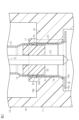
- FIG. 2 is a cross-sectional view of the connector in the same embodiment.
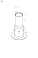
- FIG. 3 is a perspective view of the terminal unit in the same embodiment.
- FIG. 4 is a plan view of the connector in the same embodiment.
- FIG. 5 is a plan view of a connector in a modified example.
- FIG. 6 is a cross-sectional view of the connector in the same modified example.
- the connector of the present disclosure comprises: [1] A connector comprising a case having an accommodating hole and a tubular conductor accommodated in the accommodating hole by press-fitting, wherein the accommodating hole has an entrance end which is one of both axial ends of the accommodating hole and an exit end which is the other of both axial ends of the accommodating hole, the tubular conductor being inserted into the accommodating hole from the entrance end, the tubular conductor having a press-fit protrusion protruding outward, the press-fit protrusion biting into an inner circumferential surface of the accommodating hole thereby fixing the tubular conductor to the case, the accommodating hole having an extension extending from the exit end outward in the axial direction of the accommodating hole, and the press-fit protrusion biting into the extension.
- the press-fit protrusion of the tubular conductor bites into the extension extending from the exit end of the accommodating hole, making it possible to ensure a large press-fit distance from the entrance end of the accommodating hole to the position of the press-fit protrusion. Furthermore, by providing an extension in the accommodating hole, it is possible to ensure the press-fit distance while minimizing the increase in the volume of the case. Therefore, it is possible to ensure the press-fit distance and stably hold the tubular conductor in the accommodating hole while minimizing the increase in the amount of material used to form the case. Furthermore, by being able to ensure a large press-fit distance, there is less need to increase the number of press-fit protrusions. Therefore, it is possible to keep the number of press-fit protrusions small, and as a result, it is possible to obtain the desired communication performance in the tubular conductor.
- the press-fit protrusion may be provided in plurality on the cylindrical conductor, and the press-fit protrusions may be provided at the same positions as one another in the axial direction. According to this configuration, the cylindrical conductor can be more stably held in the accommodating hole by the multiple press-fit protrusions.
- the multiple press-fit protrusions may be provided at equal angular intervals in the circumferential direction. According to this configuration, the cylindrical conductor can be held in the receiving hole in a circumferentially balanced manner by the multiple press-fit protrusions provided at equal angular intervals in the circumferential direction.
- the extension portion may be annular and extend along the entire periphery of the receiving hole. According to this configuration, since the extension portion has an annular shape that follows the entire circumference of the receiving hole, it is possible to improve the rigidity of the extension portion, and thus it is possible to more stably hold the cylindrical conductor by the press-fit convex portion biting into the extension portion.
- the press-fit protrusion may be provided in multiple locations on the cylindrical conductor, the extension may be provided in multiple locations along the periphery of the receiving hole, and the multiple extensions may be provided at positions corresponding to each of the multiple press-fit protrusions.
- the cylindrical conductor can be more stably held in the accommodating hole by the multiple press-fit protrusions that bite into the multiple extending portions, respectively.
- the case may have a plurality of reinforcing ribs that individually reinforce the plurality of extensions.
- the reinforcing ribs can improve the rigidity of each extension. This makes it possible to more stably hold the tubular conductor by the press-fit protrusions biting into the extensions.
- the connector may include a terminal unit including an outer conductor as the tubular conductor, and the terminal unit may have a dielectric fixed inside the outer conductor and an inner conductor supported by the dielectric.
- the outer conductor constituting the terminal unit can be stably held in the receiving hole.
- Specific examples of the connector of the present disclosure will be described below with reference to the drawings. In each drawing, for convenience of explanation, some of the configuration may be exaggerated or simplified. In addition, the dimensional ratio of each part may differ in each drawing.
- the "cylindrical" used in the description of this specification includes not only those in which a peripheral wall is formed continuously around the entire circumference, but also those in which a plurality of parts are combined to form a cylindrical shape, and those having a notch in a part of the circumference such as a C-shape.
- the shape of the "cylindrical” includes a circle, an ellipse, and a polygon with sharp or rounded corners.
- the connector 10 of this embodiment shown in FIG. 1 is connected to, for example, an electrical device (not shown) mounted on a vehicle.
- An example of an electrical device to which the connector 10 is connected is an in-vehicle camera.
- the connector 10 includes a case 11 and a terminal unit 12 housed in the case 11 .
- the case 11 has a base 13, a fitting tube 14, and a receiving hole 15.
- the fitting tube 14 extends from the base 13 along the axis CL of the connector 10.
- the fitting tube 14 has, for example, a cylindrical shape centered on the axis CL of the connector 10. In the following description, the direction along the axis CL may be simply referred to as the "axial direction.”
- the fitting tube 14 is fitted into the connector portion of the electrical device.
- the fitting tube portion 14 has, for example, a holding portion 16 that holds the terminal unit 12 on the inner peripheral side of the fitting tube portion 14.
- the holding portion 16 extends from the inner peripheral surface of the fitting tube portion 14 to the inner peripheral side.
- the holding portion 16 has a first end face 16a and a second end face 16b, which are both axial end faces of the holding portion 16.
- the accommodation hole 15 is formed to penetrate the holding portion 16 along the axial direction.
- the accommodation hole 15 is a through hole that connects the inside of the fitting tube portion 14 and the inside of the base portion 13.
- the accommodation hole 15 is, for example, circular with the axis CL as the center.
- the accommodation hole 15 has an inlet end 15a which is one of both axial ends of the accommodation hole 15, and an outlet end 15b which is the other of both axial ends of the accommodation hole 15.
- the inlet end 15a of the accommodation hole 15 is provided on the first end surface 16a side of the holding portion 16.
- the outlet end 15b of the accommodation hole 15 is provided on the second end surface 16b side of the holding portion 16.
- the outlet end 15b is set, for example, on the same plane perpendicular to the axis CL with respect to the second end surface 16b of the holding portion 16.
- the accommodation hole 15 has an extension portion 17 that extends from the outlet end portion 15b outward in the axial direction of the accommodation hole 15.
- the extension portion 17 extends in the axial direction from the second end face 16b of the retaining portion 16 at a position corresponding to the periphery of the accommodation hole 15.
- the extension portion 17 has, for example, a continuous ring shape along the entire periphery of the accommodation hole 15.
- the extension portion 17 is formed so as to be continuous in the circumferential direction, thereby improving the rigidity of the extension portion 17. Note that, for example, a space is provided between the outer peripheral surface of the extension portion 17 and the inner peripheral surface of the fitting tube portion 14.
- Terminal unit 12 The terminal unit 12 is inserted into the receiving hole 15 along the axis CL from the inlet end 15a.
- the terminal unit 12 is connected to a terminal (not shown) of the electrical device.
- the terminal unit 12 has an outer conductor 21 as a cylindrical conductor, a dielectric 22, and an inner conductor 23.
- the outer conductor 21 has a cylindrical shape extending along the axis CL.
- the outer conductor 21 is made of, for example, a metal.
- the dielectric 22 is fixed to the inside of the outer conductor 21.
- the dielectric 22 is made of an insulator such as a synthetic resin.
- the inner conductor 23 has, for example, a columnar shape.
- the inner conductor 23 is made of, for example, a metal.
- the inner conductor 23 is fixed to the dielectric 22 in a manner that penetrates the center of the dielectric 22 in the axial direction.
- the outer conductor 21 is configured, for example, to electromagnetically shield the inner conductor 23.
- the outer conductor 21 has a tubular main body 31 extending along the axis CL and a flange 32 provided on the main body 31.
- the main body 31 is, for example, cylindrical with the axis CL as its center.
- the main body 31 has a tip 31a in the axial direction.
- the flange 32 extends, for example, from an axial base end of the main body 31 opposite the tip 31a to the outer periphery.
- the flange 32 faces, for example, a first end face 16a of the holding portion 16 in the axial direction.
- the outer conductor 21 has press-fit protrusions 33 protruding from the main body 31 to the outer periphery.
- the outer shape of the main body 31 including each press-fit protrusion 33 in the terminal unit 12 is illustrated by a two-dot chain line.
- a plurality of press-fit protrusions 33 are provided on the outer conductor 21.
- six press-fit protrusions 33 are provided on the main body 31 of the outer conductor 21.
- each of the plurality of press-fit protrusions 33 has the same shape as each other.
- the plurality of press-fit protrusions 33 are provided at equal angular intervals in the circumferential direction.
- the plurality of press-fit protrusions 33 are provided at the same positions as each other in the axial direction.
- each press-fit protrusion 33 is formed by protruding a part of the peripheral wall forming the main body 31 to the outer periphery by press working.
- the outer conductor 21 is accommodated in the accommodating hole 15 by press-fitting.
- the outer conductor 21 is inserted into the accommodating hole 15 from the entrance end 15a along the axis CL.
- each press-fit protrusion 33 bites into the inner circumferential surface of the extension portion 17 in the accommodating hole 15. This fixes the terminal unit 12 including the outer conductor 21 to the accommodating hole 15.
- the press-fit protrusion 33 bites into the extension 17 in the accommodating hole 15, thereby fixing the outer conductor 21 to the accommodating hole 15.
- This makes it possible to ensure a large press-fit distance D1, which is the axial distance from the inlet end 15a of the accommodating hole 15 to the position of the press-fit protrusion 33, and as a result, it becomes possible to stably hold the outer conductor 21 in the accommodating hole 15.
- the extension 17 is formed only at a position in the retaining portion 16 that corresponds to the periphery of the accommodating hole 15. This therefore makes it possible to suppress an increase in the volume of the case 11, i.e., an increase in the amount of material used to form the case 11, compared to a configuration in which the axial thickness of the entire retaining portion 16 is increased.
- the housing hole 15 of the case 11 has an extension 17 extending from the outlet end 15b to the outside in the axial direction of the housing hole 15.
- the press-fit convex portion 33 of the outer conductor 21 as a cylindrical conductor bites into the extension 17.
- the press-fit convex portion 33 of the outer conductor 21 bites into the extension 17 extending from the outlet end 15b of the housing hole 15, so that it is possible to secure a large press-fit distance D1 from the inlet end 15a of the housing hole 15 to the position of the press-fit convex portion 33.
- D1 the press-fit distance from the inlet end 15a of the housing hole 15 to the position of the press-fit convex portion 33.
- by providing the extension 17 in the housing hole 15 it is possible to secure the press-fit distance D1 while minimizing an increase in the volume of the case 11.
- a plurality of press-fit protrusions 33 are provided on the outer conductor 21.
- the plurality of press-fit protrusions 33 are provided at the same positions relative to one another in the axial direction. With this configuration, the plurality of press-fit protrusions 33 make it possible to more stably hold the outer conductor 21 in the receiving hole 15.
- the multiple press-fit protrusions 33 are arranged at equal angular intervals in the circumferential direction. With this configuration, the multiple press-fit protrusions 33 arranged at equal angular intervals in the circumferential direction make it possible to hold the outer conductor 21 in the receiving hole 15 in a balanced manner in the circumferential direction.
- the extension portion 17 is annular along the entire circumference of the receiving hole 15, which makes it possible to improve the rigidity of the extension portion 17. This makes it possible to more stably hold the outer conductor 21 by the press-fit protrusion 33 biting into the extension portion 17.
- the connector 10 is equipped with a terminal unit 12 including an outer conductor 21 as a tubular conductor.
- the terminal unit 12 has a dielectric 22 fixed inside the outer conductor 21 and an inner conductor 23 supported by the dielectric 22. With this configuration, the outer conductor 21 constituting the terminal unit 12 can be stably held in the receiving hole 15.
- extension portion 17 is not limited to the above embodiment, and may be changed as appropriate depending on the configuration of the connector 10.
- the extension portion 17 in the above embodiment may be changed to an extension portion 41 as shown in Figures 5 and 6.
- multiple extension portions 41 are provided along the periphery of the accommodating hole 15.
- the same number of extension portions 41 as the press-fit protrusions 33 (six as an example) are provided.
- Each extension portion 41 has the same shape as the others.
- the multiple extension portions 41 are provided at equal angular intervals in the circumferential direction. That is, the multiple extension portions 41 are provided at positions corresponding to each of the multiple press-fit protrusions 33.
- each extension portion 41 is provided at intervals from each other. That is, each extension portion 41 does not have a ring shape that is continuous in the circumferential direction like the extension portion 17 in the above embodiment.
- each extension portion 41 extends from the outlet end portion 15b of the accommodation hole 15 to the outside in the axial direction of the accommodation hole 15. In other words, each extension portion 41 extends in the axial direction from the second end face 16b of the retaining portion 16 at a position corresponding to the periphery of the accommodation hole 15.
- the case 11 has, for example, a number of reinforcing ribs 42 that individually reinforce each of the multiple extension portions 41.
- Each reinforcing rib 42 is provided integrally with each extension portion 41 on the outer periphery side of each extension portion 41.
- Each reinforcing rib 42 is connected to the second end face 16b of the holding portion 16.
- the stiffness of each extension portion 41 is improved by each reinforcing rib 42.
- an inclined surface 43 is formed on the surface of each reinforcing rib 42.
- the inclined surface 43 is inclined so that the thickness in the axial direction of the reinforcing rib 42 decreases toward the outer periphery.
- the outer conductor 21 can be held more stably in the accommodating hole 15 by the multiple press-in protrusions 33 that bite into the multiple extensions 41. Also, according to the above modification, the stiffness of each extension 41 can be improved by each reinforcing rib 42. This makes it possible to more stably hold the outer conductor 21 by each press-in protrusion 33 biting into each extension 41.
- the multiple press-fit protrusions 33 may be provided at unequal intervals in the circumferential direction.
- the number of press-fit protrusions 33 provided on the outer conductor 21 is not limited to that in the above embodiment. The number may be five or less or seven or more.
- the electrical device to which the connector 10 is connected may be an in-vehicle device other than an in-vehicle camera.
- the embodiments and modified examples disclosed herein are illustrative in all respects, and the present invention is not limited to these examples. That is, the scope of the present invention is defined by the claims, and it is intended to include all modifications within the meaning and scope of the claims.
- the multiple press-fit protrusions 33 of the terminal unit 12 may be referred to as multiple metal anchor projections that protrude radially outward.
- the extension 17 of the case 11 of the non-limiting embodiment may be referred to as a single cylindrical or annular extension provided at a radial distance from the radially inward surface of the fitting tubular portion 14 of the case 11.
- the extension 17 may have a single radially outward surface that extends continuously in the circumferential direction, a single radially inward surface that extends continuously in the circumferential direction, and an axial height (see FIG. 2).
- the axial height of the single cylindrical or annular extension may be determined according to the positions of the multiple press-fit protrusions 33 of the terminal unit 12 when the terminal unit 12 is fully attached to the case 11 (see FIG. 2).
- the single radially inward surface of the single cylindrical or annular extension may be referred to as a single anchor receiving surface that receives the multiple press-fit protrusions 33.
- the multiple extensions 41 of the case 11 in a non-limiting embodiment may be referred to as multiple discrete plates that are spaced apart from the radially inward surface of the fitting tube portion 14 of the case 11 by a radial distance and spaced apart from one another in the circumferential direction of the receiving hole 15 of the case 11.
- Each of the multiple discrete plates may have a radially inward surface and an axial height (see Figure 6).
- the axial height of the multiple discrete plates may be determined according to the positions of the multiple press-fit protrusions 33 of the terminal unit 12 when the terminal unit 12 is fully attached to the case 11 (see Figure 6).
- the multiple radially inward surfaces of the multiple discrete plates may be referred to as multiple anchor receiving surfaces that respectively receive the multiple press-fit protrusions 33.
- the axial and radial thicknesses of the extension portions 17, 41 may be smaller than the axial and radial thicknesses of the retaining portion 16.
Landscapes
- Connector Housings Or Holding Contact Members (AREA)
- Coupling Device And Connection With Printed Circuit (AREA)
Abstract
本開示は、ケースの形成材料量の増加を少なく抑えつつも、圧入距離を確保して筒状導体を収容孔に安定して保持させることを可能としたコネクタを提供する。本開示の一態様に従うコネクタ(10)は、収容孔(15)を有するケース(11)と、収容孔に圧入により収容されている筒状導体としての外導体(21)と、を備える。ケースの収容孔は、収容孔の軸方向両端部のうちの一方の端部である入口端部(15a)と、収容孔の軸方向両端部のうちの他方の端部である出口端部(15b)と、を有する。外導体は、入口端部から収容孔に挿入されている。外導体は、外周側に突出する圧入凸部(33)を有する。圧入凸部が収容孔の内周面に食い込むことで、外導体が収容孔に固定されている。収容孔(15)は、出口端部(15b)から収容孔(15)の軸方向の外側に延出する延出部(17)を有する。圧入凸部(33)は、延出部(17)に食い込んでいる。
Description
本開示は、コネクタに関するものである。
特許文献1には、収容孔を有するケースと、収容孔に圧入により収容されている筒状導体とを備えるコネクタが開示されている。ケースの収容孔は、収容孔の軸方向両端部のうちの一方の端部である入口端部と、収容孔の軸方向両端部のうちの他方の端部である出口端部とを有する。筒状導体は、入口端部から収容孔に挿入される。筒状導体は、外周側に突出する圧入凸部を有する。圧入凸部が収容孔の内周面に食い込むことで、筒状導体が収容孔に固定される。
上記のようなコネクタにおいて、本発明者らは、収容孔の入口端部から圧入凸部の位置までの軸方向の距離(以下、圧入距離と称する)が長いほど、筒状導体を収容孔に安定して保持させることができることを発見した。さらに、本発明者らは、筒状導体を収容孔に安定して保持させつつも、ケースの形成材料量の増加を如何に少なく抑えるかを検討していた。
本開示の目的は、ケースの形成材料量の増加を少なく抑えつつも、圧入距離を確保して筒状導体を収容孔に安定して保持させることを可能としたコネクタを提供することにある。
本開示のコネクタは、収容孔を有するケースと、前記収容孔に圧入により収容されている筒状導体と、を備えるコネクタであって、前記収容孔は、前記収容孔の軸方向両端部のうちの一方の端部である入口端部と、前記収容孔の軸方向両端部のうちの他方の端部である出口端部と、を有し、前記筒状導体は、前記入口端部から前記収容孔に挿入されており、前記筒状導体は、外周側に突出する圧入凸部を有し、前記圧入凸部が前記収容孔の内周面に食い込むことで、前記筒状導体が前記ケースに固定されており、前記収容孔は、前記出口端部から前記収容孔の軸方向の外側に延出する延出部を有し、前記圧入凸部は、前記延出部に食い込んでいる。
本開示のコネクタによれば、ケースの形成材料量の増加を少なく抑えつつも、圧入距離を確保して筒状導体を収容孔に安定して保持させることが可能となる。
[本開示の実施形態の説明]
最初に本開示の実施態様を列記して説明する。
本開示のコネクタは、
[1]収容孔を有するケースと、前記収容孔に圧入により収容されている筒状導体と、を備えるコネクタであって、前記収容孔は、前記収容孔の軸方向両端部のうちの一方の端部である入口端部と、前記収容孔の軸方向両端部のうちの他方の端部である出口端部と、を有し、前記筒状導体は、前記入口端部から前記収容孔に挿入されており、前記筒状導体は、外周側に突出する圧入凸部を有し、前記圧入凸部が前記収容孔の内周面に食い込むことで、前記筒状導体が前記ケースに固定されており、前記収容孔は、前記出口端部から前記収容孔の軸方向の外側に延出する延出部を有し、前記圧入凸部は、前記延出部に食い込んでいる。
最初に本開示の実施態様を列記して説明する。
本開示のコネクタは、
[1]収容孔を有するケースと、前記収容孔に圧入により収容されている筒状導体と、を備えるコネクタであって、前記収容孔は、前記収容孔の軸方向両端部のうちの一方の端部である入口端部と、前記収容孔の軸方向両端部のうちの他方の端部である出口端部と、を有し、前記筒状導体は、前記入口端部から前記収容孔に挿入されており、前記筒状導体は、外周側に突出する圧入凸部を有し、前記圧入凸部が前記収容孔の内周面に食い込むことで、前記筒状導体が前記ケースに固定されており、前記収容孔は、前記出口端部から前記収容孔の軸方向の外側に延出する延出部を有し、前記圧入凸部は、前記延出部に食い込んでいる。
この構成によれば、筒状導体の圧入凸部が収容孔の出口端部から延出する延出部に食い込むことにより、収容孔の入口端部から圧入凸部の位置までの圧入距離を大きく確保することが可能となる。また、収容孔に延出部を設けることで、ケースの体積の増加を極力抑えつつ、圧入距離を確保することが可能となる。したがって、ケースの形成材料量の増加を少なく抑えつつも、圧入距離を確保して筒状導体を収容孔に安定して保持させることが可能となる。また、圧入距離を大きく確保できることで、圧入凸部の個数を増やす必要性が小さくなる。したがって、圧入凸部の個数を少なく抑えることが可能となり、その結果、筒状導体における所望の通信性能を得ることが可能となる。
[2]上記[1]において、前記圧入凸部は、前記筒状導体に複数設けられ、前記複数の圧入凸部は、軸方向において互いに同位置に設けられていてもよい。
この構成によれば、複数の圧入凸部によって、筒状導体を収容孔により安定して保持させることが可能となる。
この構成によれば、複数の圧入凸部によって、筒状導体を収容孔により安定して保持させることが可能となる。
[3]上記[2]において、前記複数の圧入凸部は、周方向において等角度間隔に設けられていてもよい。
この構成によれば、周方向において等角度間隔に設けられた複数の圧入凸部によって、周方向においてバランスよく筒状導体を収容孔に保持させることが可能となる。
この構成によれば、周方向において等角度間隔に設けられた複数の圧入凸部によって、周方向においてバランスよく筒状導体を収容孔に保持させることが可能となる。
[4]上記[1]から[3]のいずれかにおいて、前記延出部は、前記収容孔の周縁全周に沿った環状をなしていてもよい。
この構成によれば、延出部が収容孔の周縁全周に沿った環状をなすため、延出部の剛性を向上させることが可能となる。これにより、圧入凸部が延出部に食い込むことによる筒状導体の保持をより安定させることが可能となる。
この構成によれば、延出部が収容孔の周縁全周に沿った環状をなすため、延出部の剛性を向上させることが可能となる。これにより、圧入凸部が延出部に食い込むことによる筒状導体の保持をより安定させることが可能となる。
[5]上記[1]から[3]のいずれかにおいて、前記圧入凸部は、前記筒状導体に複数設けられ、前記延出部は、前記収容孔の周縁に沿って複数設けられ、前記複数の延出部は、前記複数の圧入凸部のそれぞれに対応する位置に設けられていてもよい。
この構成によれば、複数の延出部にそれぞれ食い込む複数の圧入凸部によって、筒状導体を収容孔により安定して保持させることが可能となる。
[6]上記[5]において、前記ケースは、前記複数の延出部を個別に補強する複数の補強リブを有していてもよい。
[6]上記[5]において、前記ケースは、前記複数の延出部を個別に補強する複数の補強リブを有していてもよい。
この構成によれば、各補強リブによって、各延出部の剛性を向上させることが可能となる。これにより、各圧入凸部が各延出部に食い込むことによる筒状導体の保持をより安定させることが可能となる。
[7]上記[1]から[6]のいずれかにおいて、前記コネクタは、前記筒状導体としての外導体を含む端子ユニットを備え、前記端子ユニットは、前記外導体の内部に固定される誘電体と、前記誘電体に支持された内導体と、を有していてもよい。
この構成によれば、端子ユニットを構成する外導体を収容孔に安定して保持させることが可能となる。
[本開示の実施形態の詳細]
本開示のコネクタの具体例を、以下に図面を参照しつつ説明する。各図面では、説明の便宜上、構成の一部を誇張または簡略化して示す場合がある。また、各部分の寸法比率については各図面で異なる場合がある。なお、本明細書の説明で使用される「筒状」は、周方向全周にわたって連続して周壁が形成されたものだけではなく、複数の部品を組み合わせて筒状をなすものや、C字状のように周方向の一部に切り欠きなどを有するものも含む。また、「筒状」の形状には、円形、楕円形、及び、尖ったまたは丸い角を有する多角形が含まれる。
[本開示の実施形態の詳細]
本開示のコネクタの具体例を、以下に図面を参照しつつ説明する。各図面では、説明の便宜上、構成の一部を誇張または簡略化して示す場合がある。また、各部分の寸法比率については各図面で異なる場合がある。なお、本明細書の説明で使用される「筒状」は、周方向全周にわたって連続して周壁が形成されたものだけではなく、複数の部品を組み合わせて筒状をなすものや、C字状のように周方向の一部に切り欠きなどを有するものも含む。また、「筒状」の形状には、円形、楕円形、及び、尖ったまたは丸い角を有する多角形が含まれる。
図1に示す本実施形態のコネクタ10は、例えば、車両に搭載される図示しない電気機器に接続される。コネクタ10が接続される電気機器としては、車載カメラ等が挙げられる。
図1および図2に示すように、コネクタ10は、ケース11と、ケース11に収容される端子ユニット12とを備える。
(ケース11)
ケース11は、基部13と、嵌合筒部14と、収容孔15とを有する。嵌合筒部14は、基部13からコネクタ10の軸線CLに沿って延びている。嵌合筒部14は、例えば、コネクタ10の軸線CLを中心とする円筒状をなしている。なお、以下の説明では、軸線CLに沿った方向について、単に「軸方向」と称する場合がある。嵌合筒部14は、前記電気機器のコネクタ部に嵌合される。
(ケース11)
ケース11は、基部13と、嵌合筒部14と、収容孔15とを有する。嵌合筒部14は、基部13からコネクタ10の軸線CLに沿って延びている。嵌合筒部14は、例えば、コネクタ10の軸線CLを中心とする円筒状をなしている。なお、以下の説明では、軸線CLに沿った方向について、単に「軸方向」と称する場合がある。嵌合筒部14は、前記電気機器のコネクタ部に嵌合される。
図2に示すように、嵌合筒部14は、例えば、端子ユニット12を保持する保持部16を、嵌合筒部14の内周側に有する。保持部16は、嵌合筒部14の内周面から内周側に延びている。保持部16は、自身の軸方向の両端面である第1端面16aと第2端面16bを有している。
(収容孔15)
収容孔15は、保持部16を軸方向に沿って貫通するように形成されている。収容孔15は、嵌合筒部14の内側と基部13の内部とを繋ぐ貫通孔である。収容孔15は、例えば、軸線CLを中心とする円形をなす。収容孔15は、収容孔15の軸方向両端部のうちの一方の端部である入口端部15aと、収容孔15の軸方向両端部のうちの他方の端部である出口端部15bと、を有する。収容孔15の入口端部15aは、保持部16の第1端面16a側に設けられる。収容孔15の出口端部15bは、保持部16の第2端面16b側に設けられる。出口端部15bは、例えば、保持部16の第2端面16bに対し、軸線CLと直交する同一平面上に設定される。
収容孔15は、保持部16を軸方向に沿って貫通するように形成されている。収容孔15は、嵌合筒部14の内側と基部13の内部とを繋ぐ貫通孔である。収容孔15は、例えば、軸線CLを中心とする円形をなす。収容孔15は、収容孔15の軸方向両端部のうちの一方の端部である入口端部15aと、収容孔15の軸方向両端部のうちの他方の端部である出口端部15bと、を有する。収容孔15の入口端部15aは、保持部16の第1端面16a側に設けられる。収容孔15の出口端部15bは、保持部16の第2端面16b側に設けられる。出口端部15bは、例えば、保持部16の第2端面16bに対し、軸線CLと直交する同一平面上に設定される。
収容孔15は、出口端部15bから収容孔15の軸方向の外側に延出する延出部17を有する。延出部17は、収容孔15の周縁に対応する位置において、保持部16の第2端面16bから軸方向に延出している。延出部17は、例えば、収容孔15の周縁全周に沿った連続する環状をなしている。延出部17が周方向において連続するように形成されることで、延出部17の剛性が向上されている。なお、延出部17の外周面と嵌合筒部14の内周面との間には、例えば空間が設定されている。
(端子ユニット12)
端子ユニット12は、入口端部15aから軸線CLに沿って収容孔15に挿入されている。嵌合筒部14が前記電気機器のコネクタ部に嵌合された状態において、端子ユニット12は、当該電気機器の図示しない端子に接続される。
端子ユニット12は、入口端部15aから軸線CLに沿って収容孔15に挿入されている。嵌合筒部14が前記電気機器のコネクタ部に嵌合された状態において、端子ユニット12は、当該電気機器の図示しない端子に接続される。
端子ユニット12は、筒状導体としての外導体21と、誘電体22と、内導体23とを有する。外導体21は、軸線CLに沿って延びる筒状をなしている。外導体21は、例えば金属にて形成されている。誘電体22は、外導体21の内側に固定されている。誘電体22は、合成樹脂等の絶縁体にて形成されている。内導体23は、例えば柱状をなしている。内導体23は、例えば金属にて形成されている。内導体23は、誘電体22の中心を軸方向に貫通する態様で誘電体22に固定されている。外導体21は、例えば、内導体23を電磁シールドするように構成されている。
(外導体21)
図2および図3に示すように、外導体21は、軸線CLに沿って延びる筒状の本体部31と、本体部31に設けられたフランジ部32とを有する。本体部31は、例えば、軸線CLを中心とする円筒状をなしている。本体部31は、軸方向における先端部31aを有する。フランジ部32は、例えば、本体部31における先端部31aとは反対側の軸方向基端部から外周側に延びている。フランジ部32は、例えば、保持部16の第1端面16aに対して軸方向に対向している。
図2および図3に示すように、外導体21は、軸線CLに沿って延びる筒状の本体部31と、本体部31に設けられたフランジ部32とを有する。本体部31は、例えば、軸線CLを中心とする円筒状をなしている。本体部31は、軸方向における先端部31aを有する。フランジ部32は、例えば、本体部31における先端部31aとは反対側の軸方向基端部から外周側に延びている。フランジ部32は、例えば、保持部16の第1端面16aに対して軸方向に対向している。
(圧入凸部33)
図3および図4に示すように、外導体21は、本体部31から外周側に突出する圧入凸部33を有する。なお、図4では、端子ユニット12において、各圧入凸部33を含む本体部31の外形のみを2点鎖線で図示している。圧入凸部33は、例えば、外導体21に複数設けられている。本実施形態では、例えば6つの圧入凸部33が外導体21の本体部31に設けられている。複数の各圧入凸部33は、例えば、互いに同一形状をなしている。複数の圧入凸部33は、例えば、周方向において等角度間隔に設けられている。また、複数の圧入凸部33は、例えば、軸方向において互いに同位置に設けられている。各圧入凸部33は、例えば、本体部31を形成する周壁の一部をプレス加工にて外周側に突出させることにより形成されている。
図3および図4に示すように、外導体21は、本体部31から外周側に突出する圧入凸部33を有する。なお、図4では、端子ユニット12において、各圧入凸部33を含む本体部31の外形のみを2点鎖線で図示している。圧入凸部33は、例えば、外導体21に複数設けられている。本実施形態では、例えば6つの圧入凸部33が外導体21の本体部31に設けられている。複数の各圧入凸部33は、例えば、互いに同一形状をなしている。複数の圧入凸部33は、例えば、周方向において等角度間隔に設けられている。また、複数の圧入凸部33は、例えば、軸方向において互いに同位置に設けられている。各圧入凸部33は、例えば、本体部31を形成する周壁の一部をプレス加工にて外周側に突出させることにより形成されている。
図2および図4に示すように、外導体21は、収容孔15に対し圧入により収容されている。外導体21は、入口端部15aから軸線CLに沿って収容孔15に挿入されている。外導体21が収容孔15に圧入された状態において、各圧入凸部33は、収容孔15における延出部17の内周面に食い込んでいる。これにより、外導体21を含む端子ユニット12が収容孔15に固定されている。
本実施形態の作用について説明する。
上記のコネクタ10では、圧入凸部33が収容孔15における延出部17に食い込むことにより、外導体21が収容孔15に固定されている。したがって、収容孔15の入口端部15aから圧入凸部33の位置までの軸方向の距離である圧入距離D1を大きく確保することが可能となり、その結果、外導体21を収容孔15に安定して保持させることが可能となる。また、延出部17は、保持部16における収容孔15の周縁に対応する位置のみに形成される。したがって、保持部16全体の軸方向厚さを厚くする構成に比べて、ケース11の体積の増加、すなわち、ケース11の形成材料量の増加が抑えられている。
上記のコネクタ10では、圧入凸部33が収容孔15における延出部17に食い込むことにより、外導体21が収容孔15に固定されている。したがって、収容孔15の入口端部15aから圧入凸部33の位置までの軸方向の距離である圧入距離D1を大きく確保することが可能となり、その結果、外導体21を収容孔15に安定して保持させることが可能となる。また、延出部17は、保持部16における収容孔15の周縁に対応する位置のみに形成される。したがって、保持部16全体の軸方向厚さを厚くする構成に比べて、ケース11の体積の増加、すなわち、ケース11の形成材料量の増加が抑えられている。
また、本実施形態のように圧入距離D1が確保されることにより、例えば、圧入凸部33の個数を増やすことで、外導体21を保持する保持力を向上させる必要がなくなる。すなわち、本実施形態によれば、圧入凸部33の個数を少なく抑えることが可能となる。したがって、外導体21における所望の通信性能を得ることが可能となる。
本実施形態の効果について説明する。
(1)ケース11の収容孔15は、出口端部15bから収容孔15の軸方向の外側に延出する延出部17を有する。筒状導体としての外導体21の圧入凸部33は、延出部17に食い込んでいる。この構成によれば、外導体21の圧入凸部33が収容孔15の出口端部15bから延出する延出部17に食い込むことにより、収容孔15の入口端部15aから圧入凸部33の位置までの圧入距離D1を大きく確保することが可能となる。また、収容孔15に延出部17を設けることで、ケース11の体積の増加を極力抑えつつ、圧入距離D1を確保することが可能となる。したがって、ケース11の形成材料量の増加を少なく抑えつつも、圧入距離D1を確保して外導体21を収容孔15に安定して保持させることが可能となる。また、圧入距離D1を大きく確保することで、圧入凸部33の個数を増やす必要性が小さくなる。したがって、圧入凸部33の個数を少なく抑えることが可能となり、その結果、外導体21を含む端子ユニット12における所望の通信性能を得ることが可能となる。
(1)ケース11の収容孔15は、出口端部15bから収容孔15の軸方向の外側に延出する延出部17を有する。筒状導体としての外導体21の圧入凸部33は、延出部17に食い込んでいる。この構成によれば、外導体21の圧入凸部33が収容孔15の出口端部15bから延出する延出部17に食い込むことにより、収容孔15の入口端部15aから圧入凸部33の位置までの圧入距離D1を大きく確保することが可能となる。また、収容孔15に延出部17を設けることで、ケース11の体積の増加を極力抑えつつ、圧入距離D1を確保することが可能となる。したがって、ケース11の形成材料量の増加を少なく抑えつつも、圧入距離D1を確保して外導体21を収容孔15に安定して保持させることが可能となる。また、圧入距離D1を大きく確保することで、圧入凸部33の個数を増やす必要性が小さくなる。したがって、圧入凸部33の個数を少なく抑えることが可能となり、その結果、外導体21を含む端子ユニット12における所望の通信性能を得ることが可能となる。
(2)圧入凸部33は、外導体21に複数設けられている。複数の圧入凸部33は、軸方向において互いに同位置に設けられている。この構成によれば、複数の圧入凸部33によって、外導体21を収容孔15により安定して保持させることが可能となる。
(3)複数の圧入凸部33は、周方向において等角度間隔に設けられている。この構成によれば、周方向において等角度間隔に設けられた複数の圧入凸部33によって、周方向においてバランスよく外導体21を収容孔15に保持させることが可能となる。
(4)延出部17は、収容孔15の周縁全周に沿った環状をなしているため、延出部17の剛性を向上させることが可能となる。これにより、圧入凸部33が延出部17に食い込むことによる外導体21の保持をより安定させることが可能となる。
(5)コネクタ10は、筒状導体としての外導体21を含む端子ユニット12を備える。端子ユニット12は、外導体21の内部に固定される誘電体22と、誘電体22に支持された内導体23と、を有する。この構成によれば、端子ユニット12を構成する外導体21を収容孔15に安定して保持させることが可能となる。
(変更例)
本実施形態は、以下のように変更して実施することができる。本実施形態及び以下の変更例は、技術的に矛盾しない範囲で互いに組み合わせて実施することができる。
本実施形態は、以下のように変更して実施することができる。本実施形態及び以下の変更例は、技術的に矛盾しない範囲で互いに組み合わせて実施することができる。
・延出部17の形状等の構成は、上記実施形態に限定されるものではなく、コネクタ10の構成に応じて適宜変更してもよい。例えば、上記実施形態の延出部17を、図5および図6に示すような延出部41に変更してもよい。
図5に示すように、延出部41は、収容孔15の周縁に沿って複数設けられている。延出部41は、例えば、圧入凸部33と同数(一例として6つ)設けられている。各延出部41は、互いに同一形状をなしている。複数の延出部41は、例えば、周方向において等角度間隔に設けられている。すなわち、複数の延出部41は、複数の圧入凸部33のそれぞれに対応する位置に設けられている。周方向において、各延出部41は互いに間隔を空けて設けられている。すなわち、各延出部41は、上記実施形態の延出部17のような周方向に連続する環形状を有していない。
図6に示すように、各延出部41は、収容孔15の出口端部15bから収容孔15の軸方向の外側に延出している。換言すると、各延出部41は、収容孔15の周縁に対応する位置において、保持部16の第2端面16bから軸方向に延出している。
ケース11は、例えば、複数の延出部41をそれぞれ個別に補強する複数の補強リブ42を有している。各補強リブ42は、各延出部41の外周側において、各延出部41と一体に設けられている。各補強リブ42は、保持部16の第2端面16bと繋がっている。各補強リブ42によって、各延出部41の剛性が向上されている。また、各補強リブ42の表面には、傾斜面43が形成されている。傾斜面43は、外周側に向かって補強リブ42の軸方向に厚さが小さくなるように傾斜している。補強リブ42に傾斜面43が形成されることにより、ケース11の体積の増加を抑えつつ、補強リブ42の剛性を向上させることが可能となる。
上記のような変更例によれば、複数の延出部41にそれぞれ食い込む複数の圧入凸部33によって、外導体21を収容孔15により安定して保持させることが可能となる。また、上記のような変更例によれば、各補強リブ42によって、各延出部41の剛性を向上させることが可能となる。これにより、各圧入凸部33が各延出部41に食い込むことによる外導体21の保持をより安定させることが可能となる。
・複数の圧入凸部33は、周方向において不等間隔に設けられていてもよい。
・外導体21に設けられる圧入凸部33の個数は、上記実施形態に限定されるものではなく、5つ以下または7つ以上であってもよい。
・外導体21に設けられる圧入凸部33の個数は、上記実施形態に限定されるものではなく、5つ以下または7つ以上であってもよい。
・コネクタ10が接続される電気機器は、車載カメラ以外の車載機器であってもよい。
・今回開示された実施形態及び変更例はすべての点で例示であって、本発明はこれらの例示に限定されるものではない。すなわち、本発明の範囲は、特許請求の範囲によって示され、特許請求の範囲と均等の意味及び範囲内でのすべての変更が含まれることが意図される。
・今回開示された実施形態及び変更例はすべての点で例示であって、本発明はこれらの例示に限定されるものではない。すなわち、本発明の範囲は、特許請求の範囲によって示され、特許請求の範囲と均等の意味及び範囲内でのすべての変更が含まれることが意図される。
・図示した非限定的実施形態において、端子ユニット12の複数の圧入凸部33は、径方向外向きに突出する複数の金属アンカー突起として参照することがある。
・図4に示すように、非限定的実施形態のケース11の延出部17は、ケース11の嵌合筒部14の径方向内向き面から径方向距離をもって離れて設けられた、単一の筒状または環状の延出部として参照することがある。延出部17は、周方向に連続して広がる単一の径方向外向き面と、周方向に連続して広がる単一の径方向内向き面と、軸方向高さ(図2参照)とを有してよい。この単一の筒状または環状の延出部の前記軸方向高さは、端子ユニット12がケース11に完全に取り付けられた状態において(図2参照)、端子ユニット12の複数の圧入凸部33の位置に応じて決められ得る。この単一の筒状または環状の延出部の前記単一の径方向内向き面は、複数の圧入凸部33を受ける単一のアンカー受け面として参照することがある。
・図4に示すように、非限定的実施形態のケース11の延出部17は、ケース11の嵌合筒部14の径方向内向き面から径方向距離をもって離れて設けられた、単一の筒状または環状の延出部として参照することがある。延出部17は、周方向に連続して広がる単一の径方向外向き面と、周方向に連続して広がる単一の径方向内向き面と、軸方向高さ(図2参照)とを有してよい。この単一の筒状または環状の延出部の前記軸方向高さは、端子ユニット12がケース11に完全に取り付けられた状態において(図2参照)、端子ユニット12の複数の圧入凸部33の位置に応じて決められ得る。この単一の筒状または環状の延出部の前記単一の径方向内向き面は、複数の圧入凸部33を受ける単一のアンカー受け面として参照することがある。
・図5、6に示すように、非限定的実施形態のケース11の複数の延出部41は、ケース11の嵌合筒部14の径方向内向き面から径方向距離をもって離れて設けられ、かつ、ケース11の収容孔15の周方向に互いに隙間をおいて設けられた、複数の離散板として参照することがある。当該複数の離散板の各々は、径方向内向き面と軸方向高さ(図6参照)とを有してよい。当該複数の離散板の前記軸方向高さは、端子ユニット12がケース11に完全に取り付けられた状態において(図6参照)、端子ユニット12の複数の圧入凸部33の位置に応じて決められ得る。当該複数の離散板の前記複数の径方向内向き面は、複数の圧入凸部33をそれぞれ受ける複数のアンカー受け面として参照することがある。
・図2,6に示すように、延出部17,41の軸方向及び径方向の厚さは、保持部16の軸方向及び径方向の厚さよりも小さくてよい。
10 コネクタ
11 ケース
12 端子ユニット
13 基部
14 嵌合筒部
15 収容孔
15a 入口端部
15b 出口端部
16 保持部
16a 第1端面
16b 第2端面
17 延出部
21 外導体(筒状導体)
22 誘電体
23 内導体
31 本体部
31a 先端部
32 フランジ部
33 圧入凸部
41 延出部
42 補強リブ
43 傾斜面
CL コネクタの軸線
D1 圧入距離
11 ケース
12 端子ユニット
13 基部
14 嵌合筒部
15 収容孔
15a 入口端部
15b 出口端部
16 保持部
16a 第1端面
16b 第2端面
17 延出部
21 外導体(筒状導体)
22 誘電体
23 内導体
31 本体部
31a 先端部
32 フランジ部
33 圧入凸部
41 延出部
42 補強リブ
43 傾斜面
CL コネクタの軸線
D1 圧入距離
Claims (7)
- 収容孔を有するケースと、
前記収容孔に圧入により収容されている筒状導体と、を備えるコネクタであって、
前記収容孔は、前記収容孔の軸方向両端部のうちの一方の端部である入口端部と、前記収容孔の軸方向両端部のうちの他方の端部である出口端部と、を有し、
前記筒状導体は、前記入口端部から前記収容孔に挿入されており、
前記筒状導体は、外周側に突出する圧入凸部を有し、
前記圧入凸部が前記収容孔の内周面に食い込むことで、前記筒状導体が前記ケースに固定されており、
前記収容孔は、前記出口端部から前記収容孔の軸方向の外側に延出する延出部を有し、
前記圧入凸部は、前記延出部に食い込んでいる、
コネクタ。 - 前記圧入凸部は、前記筒状導体に複数設けられ、
前記複数の圧入凸部は、軸方向において互いに同位置に設けられている、
請求項1に記載のコネクタ。 - 前記複数の圧入凸部は、周方向において等角度間隔に設けられている、
請求項2に記載のコネクタ。 - 前記延出部は、前記収容孔の周縁全周に沿った環状をなしている、
請求項1に記載のコネクタ。 - 前記圧入凸部は、前記筒状導体に複数設けられ、
前記延出部は、前記収容孔の周縁に沿って複数設けられ、
前記複数の延出部は、前記複数の圧入凸部のそれぞれに対応する位置に設けられている、
請求項1に記載のコネクタ。 - 前記ケースは、前記複数の延出部を個別に補強する複数の補強リブを有している、
請求項5に記載のコネクタ。 - 前記筒状導体としての外導体を含む端子ユニットを備え、
前記端子ユニットは、前記外導体の内部に固定される誘電体と、前記誘電体に支持された内導体と、を有する、
請求項1に記載のコネクタ。
Priority Applications (1)
| Application Number | Priority Date | Filing Date | Title |
|---|---|---|---|
| CN202480037334.8A CN121464545A (zh) | 2023-06-14 | 2024-06-10 | 连接器 |
Applications Claiming Priority (2)
| Application Number | Priority Date | Filing Date | Title |
|---|---|---|---|
| JP2023098076A JP2024179326A (ja) | 2023-06-14 | 2023-06-14 | コネクタ |
| JP2023-098076 | 2023-06-14 |
Publications (1)
| Publication Number | Publication Date |
|---|---|
| WO2024257729A1 true WO2024257729A1 (ja) | 2024-12-19 |
Family
ID=93852013
Family Applications (1)
| Application Number | Title | Priority Date | Filing Date |
|---|---|---|---|
| PCT/JP2024/021065 Ceased WO2024257729A1 (ja) | 2023-06-14 | 2024-06-10 | コネクタ |
Country Status (3)
| Country | Link |
|---|---|
| JP (1) | JP2024179326A (ja) |
| CN (1) | CN121464545A (ja) |
| WO (1) | WO2024257729A1 (ja) |
Citations (4)
| Publication number | Priority date | Publication date | Assignee | Title |
|---|---|---|---|---|
| JPS6322796U (ja) * | 1986-07-28 | 1988-02-15 | ||
| JPH0878098A (ja) * | 1994-09-07 | 1996-03-22 | Yazaki Corp | 機器直付用シールドコネクタ |
| JP2012038713A (ja) * | 2010-07-14 | 2012-02-23 | Sumitomo Wiring Syst Ltd | シールドコネクタ |
| JP2021174639A (ja) * | 2020-04-23 | 2021-11-01 | 株式会社オートネットワーク技術研究所 | コネクタ装置 |
-
2023
- 2023-06-14 JP JP2023098076A patent/JP2024179326A/ja active Pending
-
2024
- 2024-06-10 WO PCT/JP2024/021065 patent/WO2024257729A1/ja not_active Ceased
- 2024-06-10 CN CN202480037334.8A patent/CN121464545A/zh active Pending
Patent Citations (4)
| Publication number | Priority date | Publication date | Assignee | Title |
|---|---|---|---|---|
| JPS6322796U (ja) * | 1986-07-28 | 1988-02-15 | ||
| JPH0878098A (ja) * | 1994-09-07 | 1996-03-22 | Yazaki Corp | 機器直付用シールドコネクタ |
| JP2012038713A (ja) * | 2010-07-14 | 2012-02-23 | Sumitomo Wiring Syst Ltd | シールドコネクタ |
| JP2021174639A (ja) * | 2020-04-23 | 2021-11-01 | 株式会社オートネットワーク技術研究所 | コネクタ装置 |
Also Published As
| Publication number | Publication date |
|---|---|
| JP2024179326A (ja) | 2024-12-26 |
| CN121464545A (zh) | 2026-02-03 |
Similar Documents
| Publication | Publication Date | Title |
|---|---|---|
| JP6435674B2 (ja) | モータ | |
| JP7292190B2 (ja) | グランド端子及びこれを備えたコネクタ | |
| CN109716629B (zh) | 马达 | |
| JP6159763B2 (ja) | ワンウェイクラッチのリテーナ | |
| JP2012185960A (ja) | コネクタ | |
| JP2016529450A (ja) | スラストワッシャ | |
| JP6832270B2 (ja) | レゾルバステータ | |
| CN217507723U (zh) | 弹性端子套环、端子组件和充电座 | |
| EP2492645A1 (en) | Resolver, and resolver-bearing unit including the same | |
| JP2019153399A (ja) | 接続端子 | |
| JP2024179326A (ja) | コネクタ | |
| JP2018068000A (ja) | 軸受保持構造およびモータ | |
| JP2020102328A (ja) | コネクタ | |
| US10281947B2 (en) | Mounting assembly for a control pedal of a vehicle | |
| WO2016209154A1 (en) | Mounting assembly for a control pedal of a vehicle | |
| CN219591683U (zh) | 连接器端子和连接器 | |
| JP6263330B2 (ja) | レゾルバロータ | |
| CN120674869A (zh) | 屏蔽件和连接器 | |
| JP2023110889A (ja) | コネクタソケット用接続アセンブリ | |
| JP2025059866A (ja) | コネクタ | |
| JP7151584B2 (ja) | グロメット | |
| EP3106694A1 (en) | Bearing device and method for manufacturing bearing device | |
| US20240291191A1 (en) | Connector Terminal and Connector | |
| JP2004159459A (ja) | ケーブルブッシュ | |
| JP3675562B2 (ja) | ばね式トルクリミッタ |
Legal Events
| Date | Code | Title | Description |
|---|---|---|---|
| 121 | Ep: the epo has been informed by wipo that ep was designated in this application |
Ref document number: 24823345 Country of ref document: EP Kind code of ref document: A1 |
|
| NENP | Non-entry into the national phase |
Ref country code: DE |
|
| 122 | Ep: pct application non-entry in european phase |
Ref document number: 24823345 Country of ref document: EP Kind code of ref document: A1 |