WO2024257739A1 - Déflecteur de lumière et dispositif de génération d'image - Google Patents
Déflecteur de lumière et dispositif de génération d'image Download PDFInfo
- Publication number
- WO2024257739A1 WO2024257739A1 PCT/JP2024/021108 JP2024021108W WO2024257739A1 WO 2024257739 A1 WO2024257739 A1 WO 2024257739A1 JP 2024021108 W JP2024021108 W JP 2024021108W WO 2024257739 A1 WO2024257739 A1 WO 2024257739A1
- Authority
- WO
- WIPO (PCT)
- Prior art keywords
- light
- mirror
- optical deflector
- light receiving
- reflected
- Prior art date
- Legal status (The legal status is an assumption and is not a legal conclusion. Google has not performed a legal analysis and makes no representation as to the accuracy of the status listed.)
- Ceased
Links
Images


Classifications
-
- G—PHYSICS
- G02—OPTICS
- G02B—OPTICAL ELEMENTS, SYSTEMS OR APPARATUS
- G02B26/00—Optical devices or arrangements for the control of light using movable or deformable optical elements
- G02B26/08—Optical devices or arrangements for the control of light using movable or deformable optical elements for controlling the direction of light
- G02B26/10—Scanning systems
-
- G—PHYSICS
- G02—OPTICS
- G02B—OPTICAL ELEMENTS, SYSTEMS OR APPARATUS
- G02B27/00—Optical systems or apparatus not provided for by any of the groups G02B1/00 - G02B26/00, G02B30/00
- G02B27/02—Viewing or reading apparatus
Definitions
- the present invention relates to an optical deflector and an image generating device equipped with the optical deflector.
- an image generating device that generates an image by scanning light modulated by a video signal.
- one frame of an image is generated by scanning light horizontally in a first period and vertically in a second period that is longer than the first period.
- the first period corresponds to the period of one line of the video signal
- the second period corresponds to the frame period of the video signal.
- a mirror-rotating optical deflector For example, a MEMS (Micro Electro Mechanical Systems) mirror is used as the optical deflector.
- a configuration is used to monitor the scanning position of the light, i.e., the rotational position of the scanning mirror.
- the rotational position of the scanning mirror is monitored using a PSD (Position Sensitive Detector). Specifically, monitoring light is irradiated onto the rear surface of the scanning mirror, and the reflected light is received by the PSD. A detection signal corresponding to the receiving position of the reflected light is output from the PSD. As the mirror rotates, the receiving position of the reflected light moves. The rotational position of the scanning mirror is detected from the receiving position of the reflected light at the PSD.
- PSD Position Sensitive Detector
- the first aspect of the present invention relates to an optical deflector.
- the optical deflector according to this aspect includes a movable part that rotates about a rotation axis, a scanning mirror that is disposed on the upper surface of the movable part and scans light, a projection part that projects monitor light onto the lower surface of the movable part or the upper surface of the scanning mirror, and a light receiving part that receives reflected light of the monitor light reflected on the lower surface or the upper surface.
- the light receiving part includes a two-part photodiode having two light receiving surfaces aligned along the direction in which the reflected light moves due to the rotation of the movable part, and an optical element that focuses the reflected light on the two light receiving surfaces.
- the size of the focused light spot and the size of the two light receiving surfaces are set so that the focused light spot of the reflected light straddles both of the two light receiving surfaces and does not extend beyond either of the light receiving surfaces at least in the direction in which the reflected light moves.
- the focused spot moves on the two light receiving surfaces in the direction of their alignment in response to the rotation of the scanning mirror. Therefore, the balance of the extent to which the focused spot falls on the two light receiving surfaces depends on the rotation position of the scanning mirror.
- the two sensor sections constituting the two-segment photodiode each output a light receiving signal with a balance of magnitude according to the rotation position of the scanning mirror. Therefore, a detection signal according to the rotation position of the scanning mirror can be generated from these two light receiving signals.
- each sensor unit outputs a light receiving signal with high response. Therefore, even if the scanning mirror is driven at high speed, a detection signal corresponding to the rotational position of the mirror can be obtained accurately.
- the second aspect of the present invention relates to an image generating device.
- the image generating device of this aspect includes the optical deflector of the first aspect and a control unit that controls the optical deflector based on the output from the two-segment photodiode.
- the image generating device is equipped with the photodetector according to the first aspect, so that the detection signal can be obtained accurately even when the scanning mirror is driven at high speed. Therefore, the scanning position of the light can be appropriately controlled by this detection signal.
- the present invention provides an optical deflector and an image generating device that can accurately obtain a detection signal that corresponds to the rotational position of the scanning mirror, even when the mirror is driven at high speed.
- FIG. 1 is a perspective view illustrating a schematic configuration of AR glasses according to an embodiment.
- FIG. 2 is a diagram illustrating a schematic configuration of an image generating unit according to an embodiment.
- FIG. 3 is a diagram showing the configuration of a circuit section of an image generating device according to an embodiment.
- FIG. 4 is a plan view showing a configuration of an optical deflection element included in the second optical deflector according to the embodiment.
- FIG. 5 is a graph showing an example of a drive voltage applied to a piezoelectric actuator according to an embodiment.
- FIG. 6 is a plan view of the second optical deflector including a configuration for detecting the rotation position of the second mirror according to the embodiment.
- FIG. 7 is a cross-sectional view of a second optical deflector including a configuration for detecting the rotation position of the second mirror according to an embodiment.
- 8A and 8B are diagrams each showing a schematic diagram of a method for forming the reflective surfaces of the mirrors of the projection unit and the light receiving unit according to an embodiment of the present invention.
- 9A to 9C are diagrams each showing a schematic diagram of a state in which a focused spot moves on two light receiving surfaces as the second mirror rotates, according to an embodiment.
- FIG. 10 is a graph showing a schematic relationship between the rotation angles of the second mirror and the movable portion and the detection signal according to the embodiment.
- FIG. 11 is a cross-sectional view showing the configuration of a projection section and a light receiving section according to the first modified example.
- FIG. 12 is a cross-sectional view showing the configuration of a projection section and a light receiving section according to the second modification.
- FIG. 13 is a cross-sectional view showing the configuration of a projection section and a light receiving section according to the third modified example.
- FIG. 14 is a cross-sectional view showing the configuration of a projection section and a light receiving section according to the fourth modified example.
- FIG. 15 is a cross-sectional view showing the configuration of a projection section and a light receiving section according to the fifth modified example.
- FIG. 16 is a cross-sectional view showing the configuration of a projection section and a light receiving section according to the sixth modified example.
- FIG. 12 is a cross-sectional view showing the configuration of a projection section and a light receiving section according to the second modification.
- FIG. 13 is a cross-sectional view showing the configuration of a projection section and a light receiving section according to the third modified example.
- FIG. 14 is a cross-sectional view showing the configuration of a projection
- FIG. 17 is a cross-sectional view of a second optical deflector including a configuration for detecting the rotation position of the second mirror according to another embodiment.
- FIG. 18 is a cross-sectional view showing the configuration of a projection section and a light receiving section according to the seventh modified example.
- FIG. 19 is a cross-sectional view showing the configuration of a projection section and a light receiving section according to the eighth modified example.
- FIG. 20 is a diagram showing an optical system for aligning monitor light with light for generating an image according to the eighth modified example.
- FIG. 21 is a cross-sectional view showing the configuration of a projection section and a light receiving section according to the ninth modified example.
- FIG. 22 is a cross-sectional view showing the configuration of a projection section and a light receiving section according to the tenth modification.
- FIG. 1 is a perspective view showing a schematic configuration of the AR glasses 1.
- FIG. 1 the front, back, left, right, top and bottom directions of the AR glasses 1 are indicated.
- the AR glasses 1 include a frame 2 and a pair of image generating devices 3.
- the pair of image generating devices 3 are symmetrical in the left-right direction.
- the image generating device 3 includes an image generating unit 4, a half mirror 5, and a detection unit 6.
- the AR glasses 1 are worn on the user's head, similar to regular eyeglasses.
- the image generating unit 4 is installed on the inner surface of the support part 2b.
- the image generating unit 4 projects light modulated by a video signal onto the corresponding half mirror 5.
- the half mirror 5 is installed on the inner surface of the front portion 2a.
- the half mirror 5 reflects light projected from the corresponding image generating unit 4 to the user's eye E, and transmits light traveling in the forward and backward directions.
- the light from the image generating unit 4 reflected by the half mirror 5 is irradiated onto the fovea centralis, which is located at the center of the retina in the eye E. This allows the user to visually grasp the frame image 20 (see Figure 2) generated by the image generating device 3.
- the user can see in front of the AR glasses 1 through the half mirror 5, the user can visually grasp the state in front of the AR glasses 1 by superimposing it on the frame image 20 generated by the image generating device 3.
- the pair of detection units 6 are installed on the inner surface of the front portion 2a and positioned between the pair of half mirrors 5.
- the detection units 6 are used to detect the user's line of sight. The detection of the user's line of sight will be explained later with reference to Figure 3.
- FIG. 2 is a diagram showing a schematic configuration of the image generating unit 4.
- the image generating unit 4 includes light sources 11a, 11b, and 11c, collimator lenses 12a, 12b, and 12c, apertures 13a, 13b, and 13c, a mirror 14a, dichroic mirrors 14b and 14c, a first optical deflector 15, a relay optical system 16, and a second optical deflector 17.
- Light sources 11a, 11b, and 11c are, for example, semiconductor lasers.
- Light source 11a emits laser light with a red wavelength in the range of 635 nm to 645 nm
- light source 11b emits laser light with a green wavelength in the range of 510 nm to 530 nm
- light source 11c emits laser light with a blue wavelength in the range of 440 nm to 460 nm.
- a color image is generated as the frame image 20 described below, so the image generating unit 4 is equipped with light sources 11a, 11b, and 11c capable of emitting red, green, and blue laser light.
- the image generating unit 4 may be equipped with only one light source corresponding to the color of the image.
- the image generating unit 4 may also be configured to be equipped with two light sources with different emission wavelengths.
- the light emitted from light sources 11a, 11b, and 11c is converted into parallel light by collimator lenses 12a, 12b, and 12c, respectively.
- the light transmitted through collimator lenses 12a, 12b, and 12c is shaped into a nearly circular beam by apertures 13a, 13b, and 13c, respectively.
- Mirror 14a almost completely reflects the red light that passes through aperture 13a.
- Dichroic mirror 14b reflects the green light that passes through aperture 13b and transmits the red light reflected by mirror 14a.
- Dichroic mirror 14c reflects the blue light that passes through aperture 13c and transmits the red and green light that passes through dichroic mirror 14b.
- Mirror 14a and the two dichroic mirrors 14b and 14c are positioned to align the optical axes of the light of each color emitted from light sources 11a, 11b, and 11c.
- the first optical deflector 15 reflects the light that has passed through the dichroic mirror 14c.
- the first optical deflector 15 is, for example, a MEMS (Micro Electro Mechanical System) mirror.
- the first optical deflector 15 has a configuration for rotating the first mirror M1 (scanning mirror), on which the light that has passed through the dichroic mirror 14c is incident, around a rotation axis R1 that is parallel to the vertical direction in response to a drive signal.
- the rotation of the first mirror M1 changes the reflection direction of the light.
- the light reflected by the first mirror M1 is scanned in the left-right direction (horizontal direction) on the retina of the eye E.
- the relay optical system 16 directs the light reflected by the first optical deflector 15 towards the centre of the second mirror M2 (scanning mirror) of the second optical deflector 17. That is, the light incident on the first optical deflector 15 is deflected at a predetermined deflection angle by the first mirror M1.
- the relay optical system 16 directs the light at each deflection angle towards the centre of the second mirror M2.
- the relay optical system 16 has multiple mirrors, and reflects the light reflected by the first optical deflector 15 by the multiple mirrors, directing it towards the second optical deflector 17. This allows a long optical path length to be achieved inside the relay optical system 16, and the deflection angle of the light when viewed from the second mirror M2 to be reduced.
- the second optical deflector 17 reflects the light that has passed through the relay optical system 16.
- the second optical deflector 17 is a MEMS mirror.
- the second optical deflector 17 rotates the second mirror M2, on which the light that has passed through the relay optical system 16 is incident, around a rotation axis R2 that is parallel to the left-right direction in response to a drive signal.
- the rotation of the second mirror M2 changes the reflection direction of the light.
- the light that is scanned in the left-right direction (horizontal direction) by the first optical deflector 15 is also scanned in the up-down direction (vertical direction).
- FIG. 3 shows the configuration of the circuit section of the image generating device 3.
- the detection unit 6 includes a light source 61 and an image sensor 62, and is connected to the control unit 41 of the image generation unit 4.
- the light source 61 is, for example, an LED that emits light of an infrared wavelength.
- the image sensor 62 is, for example, a CMOS image sensor or a CCD image sensor.
- the light source 61 irradiates light onto the user's eye E in response to instructions from the control unit 41.
- the image sensor 62 captures an image of the user's eye E in response to instructions from the control unit 41, and outputs the captured image to the control unit 41.
- the image generating unit 4 includes a control unit 41, a first mirror driving circuit 42, a second mirror driving circuit 43, a laser driving circuit 44, and a mirror detection circuit 45.
- the control unit 41 includes an arithmetic processing unit such as a CPU or FPGA, and a memory.
- the control unit 41 processes video signals from an external device and controls each part of the image generation unit 4.
- the control unit 41 also detects the user's line of sight based on the captured image from the detection unit 6, for example, by the dark pupil method, the bright pupil method, or the corneal reflex method.
- the control unit 41 acquires the viewpoint position in the frame image 20 formed on the user's retina based on the detected line of sight of the user.
- the first mirror drive circuit 42 drives the first mirror M1 of the first optical deflector 15 in response to a drive signal from the control unit 41.
- the second mirror drive circuit 43 drives the second mirror M2 of the second optical deflector 17 in response to a drive signal from the control unit 41.
- the control unit 41 outputs a drive signal to the second mirror drive circuit 43 so that the second mirror M2 rotates vertically (up and down) with a desired drive waveform based on the detection signal from the mirror detection circuit 45.
- the control unit 41 also controls the second mirror drive circuit 43 so that the frame image 20 is depicted at the position of the user's line of sight detected by the detection unit 6 and based on the detection signal from the mirror detection circuit 45.
- the image generating device 3 may further include a detection circuit that detects the driving state of the first mirror M1 in the first optical deflector 15, i.e., the scanning position of the light in the horizontal direction (left-right direction).
- the control unit 41 controls the first mirror driving circuit 42 based on the detection signal from this detection circuit so that the first mirror M1 rotates in the horizontal direction (left-right direction) with a desired driving waveform.
- FIG. 4 is a plan view showing the configuration of the optical deflection element 100 included in the second optical deflector 17.
- the mutually orthogonal X, Y, and Z axes are indicated.
- the positive direction of the X axis corresponds to the right direction in FIG. 1.
- the optical deflection element 100 includes a support portion 101, a pair of drive portions 102, and a movable portion 103.
- the support portion 101 is a frame-shaped member of a predetermined thickness, and is made of, for example, a silicon substrate. In a plan view, the support portion 101 has a rectangular outline.
- the driving unit 102 includes a substrate 110 having one end connected to the support unit 101 and the other end connected to the movable unit 103, and four piezoelectric actuators 111 formed on the upper surface of the substrate 110.
- the substrate 110 has a meandering shape that snakes in a direction perpendicular to the rotation axis R2.
- the thickness of the substrate 110 is constant.
- the substrate 110 is formed integrally with the support unit 101 using the same material as the support unit 101.
- the four piezoelectric actuators 111 are disposed on the upper surface of the four regions 110a of the substrate 110, which extend in a direction perpendicular to the rotation axis R2 (the Y-axis direction).
- the piezoelectric actuators 111 are configured such that a piezoelectric body of a certain thickness is sandwiched between an upper electrode and a lower electrode.
- the piezoelectric body is made of, for example, PZT (lead zirconate titanate).
- the upper and lower electrodes are made of, for example, platinum.
- a voltage drive signal
- the piezoelectric actuator 111 expands and contracts. This causes the substrate 110 to bend, generating a drive force for driving the movable part 103.
- the movable part 103 is supported by a pair of driving parts 102.
- the movable part 103 is formed integrally with the substrate 110 and the support part 101 by the same material as the substrate 110 of the driving part 102.
- the movable part 103 is circular.
- the shape of the movable part 103 may be other shapes such as a square.
- the thickness of the movable part 103 is the same as that of the substrate 110. Therefore, the movable part 103 has a disk shape.
- the above-mentioned second mirror M2 is formed on the upper surface of the movable part 103. If the reflectivity of the upper surface of the movable part 103 is high, the upper surface of the movable part 103 may be the second mirror M2.
- FIG. 5 is a graph showing an example of a drive voltage applied to the piezoelectric actuator 111.
- the horizontal axis represents time and the vertical axis represents voltage.
- the vertical and horizontal axes are each normalized.
- T0 is one period of the drive voltage. That is, the second mirror M2 rotates repeatedly during this period T0.
- a period ⁇ T is the image drawing period. That is, during the period ⁇ T, the light sources 11a to 11c emit light modulated by a video signal, and vertical scanning for image drawing is performed by the second mirror M2.
- the image generating device 3 uses a configuration for monitoring the scanning position of the light in the vertical direction, i.e., the rotational position of the second mirror M2 (scanning mirror) in the second optical deflector 17. This makes it possible to adjust the mirror scanning speed at an appropriate drawing position.
- a configuration can be used in which light for monitoring is irradiated onto the rear surface (the surface on the negative side of the Z axis) of the movable part 103, and the reflected light is received by a PSD.
- the response characteristic of the PSD is relatively gradual, so if steep speed control of the second mirror M2 (scanning mirror) is performed with a drive voltage waveform that includes high-frequency components that exceed this response characteristic, it becomes difficult to obtain an accurate detection signal.
- the second mirror M2 is controlled with a drive voltage waveform that includes high-frequency components of about 100 kHz, the detection signal from the PSD becomes rounded at the timing of the drive voltage switch shown by the dashed circle in Figure 5.
- the image generating device 3 configured as above, in order to draw a higher-resolution image, it is required to steeply control the speed of the second mirror M2 (for example, about 100 kHz).
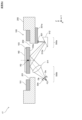
- FIG. 6 is a plan view of the second optical deflector 17 including a configuration for detecting the rotational position of the second mirror M2.
- FIG. 7 is a cross-sectional view of the second optical deflector 17 of FIG. 6 cut at position A-A by a plane parallel to the Y-Z plane.
- the outer edge of the monitor light emitted from the light source 501 is indicated by a dashed line, and the optical axis of the monitor light is indicated by a dashed line.
- the optical deflection element 100 is mounted on a frame member 200.
- the frame member 200 has a rectangular shape that is long in the X-axis direction in a plan view, and has a rectangular recess 201 into which the optical deflection element 100 fits.
- the frame member 200 has a constant thickness, and the recess 201 has a constant depth.
- the recess 201 has a rectangular opening 202 that surrounds the drive unit 102 and movable unit 103 of the optical deflection element 100 in a plan view.
- the optical deflection element 100 is mounted in the recess 201 with an adhesive or the like.
- Circuit boards 301a and 301b and support member 400 are installed on the underside of frame member 200.
- a light source 501 for emitting monitor light and a drive circuit for driving light source 501 are arranged on circuit board 301a. This drive circuit is included in mirror detection circuit 45 in FIG. 3.
- Light source 501 is formed of, for example, a light emitting diode.
- Light source 501 may also be a semiconductor laser.
- Light source 501 emits monitor light downward (negative Z-axis direction).
- the circuit board 301b is provided with a two-segment photodiode 504 and a processing circuit that processes the light receiving signal from the two-segment photodiode 504.
- This processing circuit is included in the mirror detection circuit 45 in FIG. 3.
- the two-segment photodiode 504 has two light receiving surfaces aligned in the Y-axis direction. That is, the light receiving surface of the two-segment photodiode 504 is divided into two in the Y-axis direction by a dividing line parallel to the X-axis. The two light receiving surfaces face downward (negative Z-axis direction).
- the two-segment photodiode 504 has a sensor section for each light receiving surface. These two sensor sections output light receiving signals whose magnitude corresponds to the amount of light received by the corresponding light receiving surface.
- the processing circuit described above processes these light receiving signals to generate detection signals that correspond to the rotational position of the second mirror M2.
- the configuration of the two-segment photodiode 504 and the method of generating the detection signals will be described later with reference to Figures 9(a)-(c) and 10.
- the support member 400 has a box shape with an open top.
- the support member 400 is made of a light-blocking, highly rigid material such as SUS.
- the outline of the support member 400 is the same as the outline of the frame member 200.
- the support member 400 has a rectangular recess 401 formed in a plan view. Mirrors 502 and 503 are installed in this recess 401.
- the reflecting surface 502a of the mirror 502 has a concave shape that focuses the monitor light emitted from the light source 501 on the lower surface 103a of the movable part 103.
- the reflecting surface 503a of the mirror 503 has a concave shape that focuses the reflected light of the monitor light reflected by the lower surface 103a of the movable part 103 into a focused spot.
- the light source 501, the mirrors 502, 503, and the two-segment photodiode 504 are positioned on a common plane that passes through the center of the X-axis direction of the optical deflection element 100 and is perpendicular to the rotation axis R2.
- the light source 501, the mirrors 502, 503, and the two-segment photodiode 504 are arranged so that the optical axis of the monitor light from the light source 501 to the two-segment photodiode 504 is included in this plane.
- the light source 501, mirrors 502 and 503, and two-segment photodiode 504 may be arranged on a plane parallel to the rotation axis R2 of the second mirror M2.
- the two-segment photodiode 504 is arranged so that the two light receiving surfaces are aligned in the Y-axis direction.
- the components can be arranged in the longitudinal direction of the optical deflection element 100, making it possible to reduce the overall footprint.
- Figures 8(a) and (b) are schematic diagrams showing how the reflecting surfaces 502a and 503a of the mirrors 502 and 503 are formed, respectively.
- the reflecting surface 502a of the mirror 502 has a shape that follows the shape of an ellipsoid of revolution formed by rotating an ellipse S1, which includes on its major axis L1 the light emitting point F11 of the light source 501 and the focus F12 of the monitor light set on the lower surface 103a of the movable part 103, about its major axis L1.
- a first focal length from the reflecting surface 502a to the light emitting point F11 and a second focal length from the reflecting surface 502a to the focal point F12 change according to the ratio between the major axis L1 and the minor axis of the ellipse S1.
- the ratio between the major axis L1 and the minor axis changes according to the length of the first focal length and the second focal length, and the shape of the ellipse S1 also changes.
- the shape of the ridge of the reflecting surface 502a also changes accordingly.
- the reflecting surface 503a of the mirror 503 has a shape that follows the shape of an ellipsoid of revolution formed by rotating an ellipse S2, which includes the above-mentioned focus F12 set on the lower surface 103a of the movable part 103 and the focus F13 of the monitor light on its major axis L2, about the major axis L2.
- the reflected light of the monitor light reflected by the lower surface 103a of the movable part 103 is reflected and collected by the reflecting surface 503a of the mirror 503, and focused on the focus F13.
- the focus F13 of the reflected light is positioned at a position offset from the two light receiving surfaces of the two-segment photodiode 504 in the direction perpendicular to these light receiving surfaces.
- the focus F13 is positioned on the far side of the light receiving surface of the two-segment photodiode 504 in the direction of travel of the reflected light.
- the focus F13 may also be positioned on the near side of the light receiving surface of the two-segment photodiode 504 in the direction of travel of the reflected light.
- the reflected light of the monitor light is focused on the light receiving surface of the two-segment photodiode 504 in an off-focus state.
- a focused spot of the reflected light that is larger than the focus is positioned on the two light receiving surfaces.
- the mirror 502 is also used as an optical element that focuses the monitor light emitted from the light source 501 onto the lower surface 103a of the movable part 103
- the mirror 503 is also used as an optical element that focuses the reflected light of the monitor light reflected by the lower surface 103a of the movable part 103 onto the two light receiving surfaces of the two-segment photodiode 504.
- the lower surface 103a of the movable part 103 has a reflectivity sufficient to guide a sufficient amount of reflected light to the light receiving surface of the two-segment photodiode 504.
- the area of the lower surface 103a onto which the monitor light is irradiated may be given a mirror finish, or a separate reflective film may be formed.
- Figures 9(a) to (c) are schematic diagrams showing how the focused spot SP1 moves on the light receiving surfaces Da and Db as the second mirror M2 rotates.
- the top row of Figures 9(a) to (c) shows a side view of the two-segment photodiode 504, and the bottom row of Figures 9(a) to (c) shows a plan view of the two-segment photodiode 504.
- Figure 9(a) shows the state when the second mirror M2 is near one boundary of the rotation detection range
- Figure 9(c) shows the state when the second mirror M2 is near the other boundary of the rotation detection range
- Figure 9(c) shows the state when the second mirror M2 is in the neutral position (the position in Figure 7).
- the rotation detection range refers to the range for detecting the rotation of the second mirror M2 and the movable part 103.
- the rotation detection range can be set to be slightly wider than the ideal rotation range in which the second mirror M2 and the movable part 103 rotate in the period T0 in FIG. 5.
- the two-segment photodiode 504 has two light receiving surfaces Da, Db aligned in the Y-axis direction.
- the two-segment photodiode 504 has two sensor units 504a, 504b, each of which has two light receiving surfaces Da, Db.
- the light receiving surfaces Da, Db have the same shape and size.
- the dividing line of the light receiving surfaces Da, Db is parallel to the X-axis direction.
- the focused spot SP1 of the reflected light B1 moves in the alignment direction of the light receiving surfaces Da, Db (Y-axis direction) in response to the rotation of the second mirror M2 and the movable unit 103.
- the size of the focused spot SP1 of the reflected light B1 and the size of the two light receiving surfaces Da, Db are set so that, in the above-mentioned rotation detection range, the focused spot SP1 straddles both of the two light receiving surfaces Da, Db and does not protrude from either of the light receiving surfaces Da, Db in at least the Y-axis direction.
- the size of the focused spot SP1 and the size of the two light receiving surfaces Da, Db are set so that, in the above-mentioned rotation detection range, the focused spot SP1 does not protrude from the light receiving surfaces Da, Db in not only the Y-axis direction but also the X-axis direction.
- the second mirror M2 and the movable part 103 rotate greatly in one direction, so that the focused spot SP1 of the reflected light B1 straddles the light receiving surfaces Da and Db such that the majority of the focused spot SP1 is included in the light receiving surface Da.
- the second mirror M2 and the movable part 103 rotate greatly in the other direction, so that the focused spot SP1 of the reflected light B1 straddles the light receiving surfaces Da and Db such that the majority of the focused spot SP1 is included in the light receiving surface Db.
- the state of FIG. 9(c) the second mirror M2 and the movable part 103 rotate greatly in the other direction, so that the focused spot SP1 of the reflected light B1 straddles the light receiving surfaces Da and Db such that the majority of the focused spot SP1 is included in the light receiving surface Db.
- the second mirror M2 and the movable part 103 are in a neutral position, so that the focused spot SP1 of the reflected light B1 straddles evenly the light receiving surfaces Da and Db such that half of the focused spot SP1 is included in each of the light receiving surfaces Da and Db.
- the position of the two-segment photodiode 504 is adjusted so that the focused spot SP1 falls evenly on the light receiving surfaces Da and Db when the second mirror M2 and the movable part 103 are in the neutral position.
- the extent to which the focused spot SP1 overlaps the two light receiving surfaces Da, Db changes depending on the rotational positions of the second mirror M2 and the movable part 103. Therefore, the rotational positions of the second mirror M2 and the movable part 103 can be detected by the extent to which the focused spot SP1 overlaps the two light receiving surfaces Da, Db, i.e., the balance in the magnitude of the light receiving signals output from the two sensor parts 504a, 504b.
- FIG. 10 is a graph showing a schematic relationship between the rotation angle of the second mirror M2 and the movable part 103 and the detection signal.
- the detection signal is calculated using the following formula:
- Detection signal (PD A ⁇ PD B )/(PD A +PD B ) (1)
- PD A is the magnitude of the light receiving signal output from one sensor unit 504a
- PD B is the magnitude of the light receiving signal output from the other sensor unit 504b.
- the difference between the light receiving signals PD A and PD B is divided by the sum of the light receiving signals PD A and PD B to calculate the detection signal. This makes it possible to suppress variations in the detection signal due to variations in the intensity of the reflected light B1.
- an angle of zero indicates that the second mirror M2 and the movable part 103 are in a neutral position
- the range of positive and negative angles is the range in which the second mirror M2 and the movable part 103 rotate in one direction and the other direction from the neutral position.
- the angle range in which the detection signal is parallel to the angle axis corresponds to the angle range when the focused spot SP1 is included in only one of the two light receiving surfaces Da, Db.
- the detection signal changes almost linearly in the rotation detection range from the minimum angle ⁇ min to the maximum angle ⁇ max as the rotation angle of the second mirror M2 and the movable part 103 changes. Therefore, in the rotation detection range, the rotation position of the second mirror M2 and the movable part 103 can be detected from the detection signal.
- the mirror detection circuit 45 in Fig. 3 performs amplification and noise removal processing on the light reception signals PD A and PD B output from the two sensor sections 504a and 504b of the two-segment photodiode 504.
- the mirror detection circuit 45 A/D converts the light reception signals PD A and PD B after this processing at a predetermined sampling period, and performs the calculation of the above formula (1) using the converted digital signal. In this way, the mirror detection circuit 45 sequentially outputs digital detection signals to the control section 41 at each sampling timing.
- the control unit 41 monitors the actual rotational positions of the second mirror M2 and the movable part 103 based on the graph in FIG. 10 from the received detection signal, and controls the second mirror drive circuit 43 so that the actual rotational position conforms to the ideal waveform in FIG. 5.
- the rotational position may be obtained by calculation based on the graph in FIG. 10, or may be obtained using a table that previously associates angles with the magnitude of the detection signal. In this way, the second mirror M2 and the movable part 103 rotate in an ideal rotational state.
- the detection signal is generated by the mirror detection circuit 45, but the generation of the detection signal may be performed in the control unit 41.
- the mirror detection circuit 45 is replaced with a processing circuit that performs amplification, noise removal, and A/D conversion on the light reception signals PD A and PD B output from the two sensor units 504a and 504b of the two-segment photodiode 504.
- the control unit 41 generates a detection signal from the digital light reception signals PD A and PD B input sequentially from the processing circuit by calculation of the above formula (1). Then, the control unit 41 uses this control signal to perform the above-mentioned control on the second mirror drive circuit 43.
- the focused spot SP1 moves on the two light receiving surfaces Da, Db in the arrangement direction in response to the rotation of the second mirror M2 (scanning mirror). Therefore, the balance of the extent to which the focused spot SP1 falls on the two light receiving surfaces Da, Db corresponds to the rotation position of the second mirror M2 (scanning mirror). For this reason, the two sensor sections 504a, 504b that make up the two-segment photodiode 504 each output a light receiving signal with a balance of magnitude corresponding to the rotation position of the second mirror M2 (scanning mirror). Therefore, from these two light receiving signals, a detection signal corresponding to the rotation position of the second mirror M2 (scanning mirror) can be generated using the above formula (1).
- each sensor unit 504a, 504b outputs a light receiving signal with high response. Therefore, even if the second mirror M2 (scanning mirror) is driven at high speed, a detection signal according to the rotational position of the second mirror M2 (scanning mirror) can be accurately obtained.
- the light receiving unit 500b includes a mirror 503 that reflects the reflected light of the monitor light and directs it toward the two-segment photodiode 504. In this way, the reflected light of the monitor light is turned back by the mirror 503 and directed toward the two-segment photodiode 504, so that the light receiving unit 500b can be made smaller in height. This allows the shape of the second optical deflector 17 (optical deflector) to be made compact.
- the reflecting surface 503a of the mirror 503 has a concave shape that focuses the reflected light of the monitor light on the focusing spot SP1, and the mirror 503 is also used as an optical element that focuses the reflected light of the monitor light on the two light receiving surfaces Da and Db. This allows the number of parts in the light receiving unit 500b to be reduced, and the configuration of the second optical deflector 17 (optical deflector) to be simplified.
- the projection unit 500a includes a mirror 502 (another optical element) that focuses the monitor light on the lower surface 103a of the movable unit 103, and the reflecting surface 503a of the mirror 503 on the light receiving unit 500b side has a shape along an ellipsoid of revolution formed by rotating an ellipse S2 containing the focus F12 of the monitor light on its major axis L2 about the major axis L2, as shown in FIG. 8(b), and the focus F13 of the reflected light contained on the major axis L2 is positioned at a position that is offset in a direction perpendicular to the two light receiving surfaces of the two-segment photodiode 504.
- This allows the reflected light of the monitor light reflected by the lower surface 103a of the movable unit 103 to be properly focused on the light receiving surfaces Da and Db of the two-segment photodiode 504 by the reflecting surface 503a.
- the projection unit 500a includes a light source 501 that emits monitor light, and a mirror 502 (another optical element) that focuses the monitor light emitted from the light source 501 on the lower surface 103a of the movable unit 103. This significantly reduces the area of the lower surface 103a onto which the monitor light is irradiated, allowing for greater freedom in designing the optical deflection element 100.
- the projection unit 500a includes a mirror 502 that reflects the monitor light emitted from the light source 501 and directs it toward the lower surface 103a of the movable unit 103. In this way, by turning the monitor light back at the mirror 502 and directing it toward the lower surface 103a of the movable unit 103, the projection unit 500a can be made smaller in the height direction. This allows the shape of the second optical deflector 17 (optical deflector) to be made compact.
- the reflecting surface 502a of the mirror 502 has a concave shape that focuses the monitor light on the lower surface 103a of the movable part 103, and the mirror 502 is also used as another optical element that focuses the monitor light on the lower surface 103a of the movable part 103. This reduces the number of parts in the projection part 500a and simplifies the configuration of the second optical deflector 17 (optical deflector).
- the reflecting surface 502a of the mirror 502 has a shape that follows an ellipsoid of revolution formed by rotating an ellipse S1, which includes the light emitting point F11 of the light source 501 and the focal point F12 of the monitor light on its major axis L1, about the major axis L1. This allows the monitor light emitted from the light source 501 to be properly focused on the lower surface 103a of the movable part 103.
- the projection unit 500a and the light receiving unit 500b are placed in a recess 401 of a support member 400 made of a light-shielding material, and are surrounded by the support member 400. This makes it difficult for stray light to enter the two-part photodiode 504, and makes it possible to accurately obtain a detection signal that corresponds to the rotational position of the second mirror M2.
- FIG. 11 is a cross-sectional view showing the configuration of the projection unit 500a and the light receiving unit 500b in the first modified example.
- FIG. 11 hatching is omitted for the members that make up the projection unit 500a and the light receiving unit 500b, and the support member 400 is not shown.
- the recess 401 of the support member 400 only needs to be configured to be able to support the optical members of the projection unit 500a and the light receiving unit 500b.
- the monitor light emitted from the light source 501 is irradiated onto the lower surface 103a of the movable part 103 without being focused.
- the reflected light of the monitor light reflected by the lower surface 103a of the movable part 103 is focused by the lens 511 onto the light receiving surfaces Da, Db of the two-segment photodiode 504.
- the focus F21 of the reflected light is positioned on the far side of the light receiving surfaces Da, Db in the direction of travel of the reflected light.
- the optical axis of the monitor light from the light source 501 to the two-segment photodiode 504 is included in a common plane parallel to the Y-Z plane.
- the two light receiving surfaces Da, Db are aligned in the direction in which the focused spot SP1 moves due to the rotation of the movable part 103.
- the optical axis of the reflected light passes through the dividing line of the light receiving surfaces Da, Db perpendicular to the plane including the light receiving surfaces Da, Db, as in the case of FIG. 9B.
- the focused spot SP1 moves on the two light receiving surfaces Da, Db in response to the rotation of the second mirror M2 and the movable part 103, and the extent to which the focused spot SP1 fits onto the two light receiving surfaces Da, Db changes. Therefore, as in the above embodiment, the rotation position of the second mirror M2 can be detected based on the light receiving signal output from the two-segment photodiode 504.
- FIG. 12 is a cross-sectional view showing the configuration of a projection section 500a and a light receiving section 500b according to the second modification.
- a mirror 512 is added to the configuration of the first modification.
- the mirror surface 512a of the mirror 512 is flat.
- the light source 501 is disposed on the circuit board 301a and emits monitor light downward.
- This configuration also achieves the same effect as modified example 1. Furthermore, in this configuration, the monitor light is reflected by the mirror 512 and directed to the lower surface 103a of the movable part 103, so that the projection part 500a can be made smaller in height than in the configuration of modified example 1, and the shape of the second optical deflector 17 (optical deflector) can be made more compact.
- FIG. 13 is a cross-sectional view showing the configuration of a projection section 500a and a light receiving section 500b according to the third modified example.
- a mirror 513 is added to the configuration of the second modification.
- the mirror surface 513a of the mirror 513 is flat.
- the two-segment photodiode 504 is arranged facing downward on the circuit board 301b.
- the relationship between the focused spot SP1 and the light receiving surfaces Da and Db is the same as in Figures 9(a) to (c).
- This configuration also achieves the same effects as those of modified examples 1 and 2. Furthermore, in this configuration, the reflected light of the monitor light reflected by the lower surface 103a of the movable part 103 is reflected by the mirror 513 and guided to the two-segment photodiode 504, so that the light receiving part 500b can be made smaller in height than in the configurations of modified examples 1 and 2, and the shape of the second optical deflector 17 (optical deflector) can be made more compact.
- a lens 514 is added to the configuration of the second modification.
- the lens 514 focuses the monitor light emitted from the light source 501 onto the lower surface 103a of the movable part 103.
- This configuration also achieves the same effects as the first and second modifications. Furthermore, in this configuration, the monitor light emitted from the light source 501 is focused on the lower surface 103a of the movable part 103, so the area of the lower surface 103a onto which the monitor light is irradiated can be significantly reduced. This allows for greater freedom in the design of the optical deflection element 100.
- reflected light of the monitor light occurs from the focal point of the monitor light set on the lower surface 103a. Therefore, by omitting the lens 511 and bringing the two-segment photodiode 504 closer to this focal point, it is possible to guide a relatively small focused spot SP1 to the light receiving surfaces Da, Db of the two-segment photodiode 504. As a result, as in the above embodiment, a detection signal corresponding to the rotational position of the second mirror M2 can be accurately generated from the light receiving signal from the two-segment photodiode 504.
- the lens 514 of the projection unit 500a is shared as an optical element on the light receiving unit 500b side that focuses the reflected light of the monitor light on the two light receiving surfaces Da, Db.
- the lens 511 may be omitted from the configuration of FIG. 14, and the lens 514 of the projection unit 500a may be configured to focus the monitor light on the focal point F12 instead of the lower surface 103a.
- the monitor light is irradiated onto the lower surface 103a of the movable unit 103 in an off-focus state.
- a detection signal corresponding to the rotational position of the second mirror M2 can be accurately generated from the light receiving signal from the two-segment photodiode 504.
- the lens 514 of the projection unit 500a is shared as an optical element on the light receiving unit 500b side that focuses the reflected light of the monitor light on the two light receiving surfaces Da and Db.
- the configuration of the light receiving section 500b is modified compared to the configuration in FIG. 7. That is, in the configuration in FIG. 15, the reflected light of the monitor light reflected by the lower surface 103a of the movable section 103 is focused by the lens 511 onto the light receiving surfaces Da, Db of the two-segment photodiode 504.
- the focal point F21 of the reflected light is positioned on the far side of the light receiving surfaces Da, Db in the traveling direction of the reflected light.
- this configuration also allows accurate detection of the rotation state of the second mirror M2 based on the light receiving signal from the two-segment photodiode 504. Also, as in the configuration of FIG. 14, in this configuration too, the lens 511 may be omitted and the reflected light of the monitor light may be guided directly to the light receiving surfaces Da and Db.
- FIG. 16 is a cross-sectional view showing the configuration of a projection section 500a and a light receiving section 500b according to the sixth modified example.
- the second optical deflector 17 includes a projection unit 500a that projects monitor light L11 onto the upper surface of the second mirror M2, and a light receiving unit 500b that receives the reflected light of the monitor light L11 reflected by the upper surface of the second mirror M2.
- the projection unit 500a includes a light source 501 and a mirror 502
- the light receiving unit 500b includes a mirror 503 and a two-segment photodiode 504.
- the configuration of the projection unit 500a and the light receiving unit 500b is the same as in the above embodiment, except that the projection target of the monitor light L11 (the reflection target of the monitor light L11) is the upper surface of the second mirror M2.
- the reflecting surfaces 502a, 503a of the mirrors 502, 503 are shaped along the respective ellipsoids of revolution.
- the mirrors 502, 503 focus the monitor light L11 emitted from the light source 501 near the center of the upper surface of the second mirror M2.
- the mirror 503 focuses the monitor light L11 reflected by the second mirror M2 at a position offset in the direction perpendicular to the two light receiving surfaces of the two-segment photodiode 504.
- the light source 501 and the two-segment photodiode 504 are mounted on the upper surface of the circuit board 300.
- a drive circuit for driving the light source 501 and the two-segment photodiode 504 is mounted on the circuit board 300.
- the mirrors 502 and 503 are mounted on the underside of a glass substrate 600 mounted on the support member 400.
- Light L10 for generating an image modulated by a video signal passes through the glass substrate 600 and enters the second mirror M2.
- a light shielding means 601 is provided on the underside of the glass substrate 600 in an area other than the area through which the light L10 passes.
- the focused spot SP1 moves on the two light receiving surfaces Da, Db in the arrangement direction in response to the rotation of the second mirror M2 (scanning mirror). Therefore, the balance of the coverage of the focused spot SP1 on the two light receiving surfaces Da, Db corresponds to the rotation position of the second mirror M2 (scanning mirror).
- the two sensor sections 504a, 504b constituting the two-segment photodiode 504 each output a light receiving signal with a balance of magnitude corresponding to the rotation position of the second mirror M2 (scanning mirror). Therefore, from these two light receiving signals, a detection signal corresponding to the rotation position of the second mirror M2 (scanning mirror) can be generated using the above formula (1).
- each sensor unit 504a, 504b outputs a light receiving signal with high response. Therefore, even if the second mirror M2 (scanning mirror) is driven at high speed, a detection signal according to the rotational position of the second mirror M2 (scanning mirror) can be accurately obtained.
- FIG. 18 is a cross-sectional view showing the configuration of the projection unit 500a and the light receiving unit 500b in the seventh modified example.
- the monitor light L11 emitted from the light source 501 is irradiated onto the upper surface of the second mirror M2 without being focused.
- the reflected light of the monitor light L11 reflected by the second mirror M2 is focused by the lens 511 onto the light receiving surfaces Da, Db of the two-segment photodiode 504.
- the focus F21 of the reflected light is positioned on the far side of the light receiving surfaces Da, Db in the direction of travel of the reflected light.
- the optical axis of the monitor light L11 reaching the two-segment photodiode 504 from the light source 501 is included in a common plane parallel to the Y-Z plane.
- the two light receiving surfaces Da, Db are aligned in the direction in which the focused spot SP1 moves due to the rotation of the movable part 103.
- the optical axis of the reflected light passes through the dividing line of the light receiving surfaces Da, Db perpendicular to the plane including the light receiving surfaces Da, Db, as in the case of FIG. 9B.
- the focused spot SP1 moves on the two light receiving surfaces Da, Db in response to the rotation of the second mirror M2 and the movable part 103, and the extent to which the focused spot SP1 fits onto the two light receiving surfaces Da, Db changes. Therefore, as in the above embodiment, the rotation position of the second mirror M2 can be detected based on the light receiving signal output from the two-segment photodiode 504.
- FIG. 19 is a cross-sectional view showing the configuration of a projection section 500a and a light receiving section 500b according to the eighth modified example.
- the light source 501 is omitted compared to modification example 7.
- monitor light L11 is emitted from the image generating unit 4 in FIG. 3 together with light L10 for image generation.
- the projection unit 500a includes a dichroic mirror 515, a mirror 516, and a lens 514.
- the dichroic mirror 515 reflects the monitor light L11 and transmits the light L10.
- the light L0 transmitted through the dichroic mirror 515 is incident on the second mirror M2 near the center in the Y-axis direction.
- the monitor light L11 reflected by the dichroic mirror 515 is reflected by the mirror 516 and then focused by the lens 514 near the center in the Y-axis direction of the second mirror M2.
- the configuration of the light receiving unit 500b is the same as that of the seventh modification of FIG. 18.
- the light source 501 and its drive circuit can be omitted from the second optical deflector 17. This simplifies the configuration of the second optical deflector 17.
- the monitor light L11 is also scanned by the first optical deflector 15.
- the scanning direction is parallel to the dividing line of the light receiving surfaces Da, Db in FIGS. 9(a) to 9(c). Therefore, even if the monitor light L11 is scanned by the first optical deflector 15, the focused spot SP1 moves on the two light receiving surfaces Da, Db in accordance with the rotation of the second mirror M2 and the movable part 103, and the degree to which the focused spot SP1 fits the two light receiving surfaces Da, Db changes. Therefore, as in the above embodiment, the rotation position of the second mirror M2 can be detected based on the light receiving signal output from the two-segment photodiode 504. This is also true for the ninth modified example below.
- FIG. 21 is a cross-sectional view showing the configuration of a projection section 500a and a light receiving section 500b according to the ninth modified example.
- the projection unit 500a is omitted, and a dichroic mirror 515 is added to the light receiving unit 500b.
- the projection unit that projects the monitor light L11 onto the upper surface of the second mirror M2 is composed of the light source 11d, collimator lens 12d, aperture 13d, and dichroic mirror 14d shown in FIG. 20.
- the light L10 and monitor light L11 whose optical axes are aligned by the optical system in FIG. 20, enter near the center of the second mirror M2 and are reflected by the second mirror M2.
- the dichroic mirror 515 reflects the monitor light L11 and transmits the light L10.
- the monitor light L11 reflected by the dichroic mirror 515 is focused by the lens 511 onto the light receiving surface of the two-segment photodiode 504.
- the state in which the monitor light L11 is focused on the two-segment photodiode 504 is the same as in the seventh modification.
- the configuration of modification example 9 further omits the projection unit 500a. This further simplifies the configuration of the second optical deflector 17.
- FIG. 22 is a cross-sectional view showing the configuration of a projection section 500a and a light receiving section 500b according to the tenth modification.
- a half-wave plate 517 and polarizing beam splitters 518a and 518b are added to the configuration of the eighth modification in FIG. 18.
- the polarizing beam splitters 518a and 518b are disposed in the optical path of the light L10 for generating an image, and combine and separate the monitor light L11 emitted from the light source 501 into the light L10.
- the half-wave plate 517 adjusts the polarization direction of the monitor light L11 (laser light) emitted from the light source 501 so that it becomes S-polarized with respect to the polarizing beam splitter 518a.
- the polarization direction of the light L10 becomes P-polarized with respect to the polarizing beam splitter 518a.
- the polarizing beam splitter 518a aligns the optical axis of the reflected monitor light L11 with the optical axis of the transmitted light L10.
- Light L10 and monitor light L11 whose optical axes are aligned by the polarizing beam splitter 518a, are incident on the second mirror M2 near the center in the Y-axis direction and are reflected by the second mirror M2.
- light L10 and monitor light L11 reflected by the second mirror M2 light L10 passes through the polarizing beam splitter 518b, and monitor light L11 is reflected by the polarizing beam splitter 518b.
- the monitor light L11 is then focused by the lens 511 on the light receiving surface of the two-segment photodiode 504.
- the state of focus of the monitor light L11 on the two-segment photodiode 504 is the same as in the seventh modified example above.
- the lower surface 103a of the movable part 103 is a uniform plane, but as long as the monitor light is properly reflected and received by the two-segment photodiode 504 when the movable part 103 rotates, the lower surface 103a of the movable part 103 does not have to be a uniform plane, and for example, a rib may be provided near the outer periphery of the lower surface 103a of the movable part 103.
- a rib is provided on the lower surface 103a, as in the above embodiment and modified examples 4 to 6, it is preferable to focus the monitor light on the lower surface 103a of the movable part 103 and limit the area of the lower surface 103a onto which the monitor light is irradiated as small as possible. This makes it possible to prevent the monitor light from being blocked by the rib, and increases the degree of freedom in designing the optical deflection element 100.
- the width of the light receiving surfaces Da, Db in the X-axis direction is wider than the size of the focused spot SP1 in the X-axis direction, but as long as a detection signal that changes in one direction according to the rotation angle is obtained in the rotation detection range of Figure 10, the width of the light receiving surfaces Da, Db in the X-axis direction may be smaller than the size of the focused spot SP1 in the X-axis direction.
- the shapes of the light receiving surfaces Da, Db are not limited to those shown in Figures 9(a) to (c). This is also the case in the other embodiments above.
- the configuration of the present invention is used to detect the scanning position of light in the vertical direction, but the configuration of the present invention may also be used to detect the scanning position of light in the horizontal direction.
- the configuration of the projection unit 500a and the light receiving unit 500b is applied to the first optical deflector 15. This point is similar to the other embodiments described above.
- the present invention is applied to the image generating device 3 mounted on the AR glasses 1, but the image generating device to which the present invention is applied is not limited to this.
- the present invention can be used in various devices so long as it detects the rotational position of a mirror for optical scanning.
- the configurations of the projection unit 500a and the light receiving unit 500b according to the present invention are not limited to the configurations shown in the above embodiment, modified examples 1 to 6, other embodiments, and modified examples 7 to 10, and other modifications are possible.
- the calculation formula for calculating the detection signal is also not limited to the above formula (1).
- the light receiving unit is a two-part photodiode having two light receiving surfaces aligned along a direction in which the reflected light moves as the movable part rotates; an optical element that focuses the reflected light onto the two light receiving surfaces; a size of the focused spot of the reflected light and a size of the two light receiving surfaces are set so that, within a rotation detection range for detecting the rotation of the movable part, the focused spot of the reflected light straddles both of the two light receiving surfaces and does not protrude from either of the light receiving surfaces at least in a direction in which the reflected light moves.
- An optical deflector comprising:
- the focused spot moves on the two light receiving surfaces in the alignment direction in response to the rotation of the scanning mirror. Therefore, the balance of the extent to which the focused spot falls on the two light receiving surfaces corresponds to the rotation position of the scanning mirror.
- the two sensor sections that make up the two-segment photodiode each output a light receiving signal with a balance of magnitude that corresponds to the rotation position of the scanning mirror. Therefore, a detection signal that corresponds to the rotation position of the scanning mirror can be generated from these two light receiving signals.
- the response characteristics of the photodiode are high, even if the scanning mirror is driven at high speed, each sensor section outputs a light receiving signal with high response. Therefore, even if the scanning mirror is driven at high speed, a detection signal that corresponds to the rotation position of the mirror can be accurately obtained.
- the optical element is a lens.
- An optical deflector comprising:
- This technology allows the reflected light of the monitor light to be focused onto the light receiving surface of a two-segment photodiode with a simple configuration.
- the light receiving unit further includes a mirror that reflects the reflected light toward the two-segment photodiode.
- An optical deflector comprising:
- the reflected monitor light is reflected by a mirror and directed to a two-part photodiode, making it possible to miniaturize the light receiving section in the height direction and to make the shape of the optical deflector more compact.
- the reflective surface of the mirror has a concave shape that focuses the reflected light onto the focused spot;
- the mirror is commonly used as the optical element.
- This technology reduces the number of components in the light receiving section, simplifying the structure of the optical deflector.
- the projection unit includes another optical element that focuses the monitor light near a lower surface of the movable unit or near an upper surface of the scanning mirror;
- the reflecting surface of the mirror has a shape conforming to an ellipsoid of revolution formed by rotating an ellipse, the major axis of which includes the focus of the monitor light, about the major axis;
- a focal point of the reflected light included on the long axis is positioned at a position offset from the two light receiving surfaces in a direction perpendicular to the light receiving surfaces.
- the monitor light reflected by the bottom surface of the moving part can be properly focused onto the light receiving surface of the two-segment photodiode by the reflective surface of the mirror.
- the projection unit includes: a light source that emits the monitor light; and another optical element that focuses the monitor light emitted from the light source near the lower surface of the movable part or near the upper surface of the scanning mirror.
- An optical deflector comprising:
- This technology significantly reduces the area of the underside of the moving part onto which the monitor light is irradiated, allowing greater freedom in the design of the optical deflector.
- the optical element of the projection unit is a lens. 1.
- An optical deflector comprising:
- This technology allows the monitor light to be focused near the bottom surface of the moving part with a simple configuration.
- the projection unit further includes a mirror that reflects the monitor light emitted from the light source toward a lower surface of the movable unit or an upper surface of the scanning mirror.
- An optical deflector comprising:
- the reflecting surface of the mirror has a concave shape that focuses the monitor light near the bottom surface of the movable portion or near the top surface of the scanning mirror;
- the mirror is commonly used as the other optical element.
- the reflecting surface of the mirror has a shape conforming to an ellipsoid of revolution formed by rotating an ellipse, the major axis of the ellipse including the light emitting point of the light source and the focal point of the monitor light, about the major axis;
- This technology allows the monitor light emitted from the light source to be properly focused near the bottom surface of the movable part.
- the projection unit projects monitor light onto a lower surface of the movable unit; the light receiving unit receives reflected light of the monitor light reflected on the lower surface.
- An optical deflector comprising:
- An optical deflector according to any one of the first to eleventh aspects of the present invention; a control unit that controls the optical deflector based on an output from the two-segment photodiode.
- An image generating device comprising:
- the image generating device is equipped with the optical deflector described above, so that the detection signal can be obtained accurately even when the scanning mirror is driven at high speed. Therefore, the scanning position of the light can be appropriately controlled by this detection signal.
Landscapes
- Physics & Mathematics (AREA)
- General Physics & Mathematics (AREA)
- Optics & Photonics (AREA)
- Mechanical Light Control Or Optical Switches (AREA)
Abstract
L'invention concerne un second déflecteur de lumière (17) qui est pourvu : d'une partie mobile (103) qui tourne autour d'un arbre rotatif (R2) ; d'un second miroir (M2) (miroir de balayage) qui est disposé sur une surface supérieure de la partie mobile (103) et qui est destiné à balayer la lumière ; d'une partie de projection (500a) qui projette une lumière de surveillance sur une surface inférieure (103a) de la partie mobile (103) ou une surface supérieure du second miroir (M2) ; et d'une partie de réception de lumière (500b) qui reçoit la lumière réfléchie de la lumière de surveillance réfléchie par la surface inférieure (103a) ou la surface supérieure du second miroir (M2). La partie de réception de lumière (500b) comprend : une photodiode à deux divisions (504) ayant deux surfaces de réception de lumière disposées le long de la direction dans laquelle la lumière réfléchie se déplace par la rotation de la partie mobile (103) ; et un miroir (503) (élément optique) qui condense la lumière réfléchie sur les deux surfaces de réception de lumière.
Applications Claiming Priority (2)
| Application Number | Priority Date | Filing Date | Title |
|---|---|---|---|
| JP2023-098149 | 2023-06-14 | ||
| JP2023098149 | 2023-06-14 |
Publications (1)
| Publication Number | Publication Date |
|---|---|
| WO2024257739A1 true WO2024257739A1 (fr) | 2024-12-19 |
Family
ID=93852012
Family Applications (1)
| Application Number | Title | Priority Date | Filing Date |
|---|---|---|---|
| PCT/JP2024/021108 Ceased WO2024257739A1 (fr) | 2023-06-14 | 2024-06-10 | Déflecteur de lumière et dispositif de génération d'image |
Country Status (1)
| Country | Link |
|---|---|
| WO (1) | WO2024257739A1 (fr) |
Citations (6)
| Publication number | Priority date | Publication date | Assignee | Title |
|---|---|---|---|---|
| US4564757A (en) * | 1982-09-30 | 1986-01-14 | Burroughs Corporation | Mirror position sensor for improved track selection in optical data disk system |
| JP2004053503A (ja) * | 2002-07-23 | 2004-02-19 | Olympus Corp | 偏向角検出装置 |
| JP2006195083A (ja) * | 2005-01-12 | 2006-07-27 | Sharp Corp | 光走査装置 |
| JP2010117353A (ja) * | 2008-11-14 | 2010-05-27 | Berkin Bv | コリオリ型流量センサシステム |
| JP2014006299A (ja) * | 2012-06-21 | 2014-01-16 | Olympus Corp | 角度検出装置および走査型顕微鏡システム |
| CN112859048A (zh) * | 2019-11-27 | 2021-05-28 | 上海禾赛科技股份有限公司 | 光束扫描装置、包括其的激光雷达和控制方法 |
-
2024
- 2024-06-10 WO PCT/JP2024/021108 patent/WO2024257739A1/fr not_active Ceased
Patent Citations (6)
| Publication number | Priority date | Publication date | Assignee | Title |
|---|---|---|---|---|
| US4564757A (en) * | 1982-09-30 | 1986-01-14 | Burroughs Corporation | Mirror position sensor for improved track selection in optical data disk system |
| JP2004053503A (ja) * | 2002-07-23 | 2004-02-19 | Olympus Corp | 偏向角検出装置 |
| JP2006195083A (ja) * | 2005-01-12 | 2006-07-27 | Sharp Corp | 光走査装置 |
| JP2010117353A (ja) * | 2008-11-14 | 2010-05-27 | Berkin Bv | コリオリ型流量センサシステム |
| JP2014006299A (ja) * | 2012-06-21 | 2014-01-16 | Olympus Corp | 角度検出装置および走査型顕微鏡システム |
| CN112859048A (zh) * | 2019-11-27 | 2021-05-28 | 上海禾赛科技股份有限公司 | 光束扫描装置、包括其的激光雷达和控制方法 |
Similar Documents
| Publication | Publication Date | Title |
|---|---|---|
| EP2793080B1 (fr) | Système de projection à mise au point automatique | |
| JP5281923B2 (ja) | 投射型表示装置 | |
| US20080151185A1 (en) | Retinal scanning image display apparatus and image display system | |
| JP3277776B2 (ja) | 放射温度計の照準装置 | |
| JP6663045B2 (ja) | レーザ機械加工中にプロセス監視するためのデバイスであって光学式間隔測定装置とプリズム偏光ユニットで構成されるデバイス、並びに、当該デバイスを搭載したレーザ加工ヘッド | |
| JP7302592B2 (ja) | 情報検出装置、映像投影装置、情報検出方法、及び映像投影方法 | |
| CN110832380B (zh) | 用于校准数据眼镜的投影装置的方法以及用于执行方法的数据眼镜的投影装置 | |
| JP7230443B2 (ja) | 距離測定装置及び移動体 | |
| CN116457717A (zh) | 用于智能眼镜的光学装置 | |
| WO2001059505A1 (fr) | Dispositif de condensation de laser et appareil d'usinage au laser | |
| JP7163230B2 (ja) | 視線検出装置、視線検出方法、及び表示装置 | |
| KR101428864B1 (ko) | 초점 위치 변경 장치 및 이를 이용한 공초점 광학 장치 | |
| US20250314877A1 (en) | Method and system for using characterization light to detect fiber position in a fiber scanning projector | |
| US20030142086A1 (en) | Image projecting device | |
| US20150253130A1 (en) | Device for generating an optical dot pattern | |
| US20220299759A1 (en) | Light deflector, image projection apparatus, and distance-measuring apparatus | |
| WO2024257739A1 (fr) | Déflecteur de lumière et dispositif de génération d'image | |
| WO2018179860A1 (fr) | Module laser et dispositif de projection d'image | |
| JPH06265773A (ja) | 顕微鏡自動焦点装置 | |
| JP4590916B2 (ja) | 画像表示装置 | |
| US20240353533A1 (en) | Distance measurement device | |
| JP4589931B2 (ja) | 小型光走査装置 | |
| US12607846B2 (en) | Reflector device for emitting a plurality of reflected beams from a single main light beam | |
| JP2926777B2 (ja) | 形状計測装置 | |
| JPH08334309A (ja) | 光学式変位検出装置 |
Legal Events
| Date | Code | Title | Description |
|---|---|---|---|
| 121 | Ep: the epo has been informed by wipo that ep was designated in this application |
Ref document number: 24823355 Country of ref document: EP Kind code of ref document: A1 |
|
| NENP | Non-entry into the national phase |
Ref country code: DE |