WO2024257739A1 - 光偏向器および画像生成装置 - Google Patents
光偏向器および画像生成装置 Download PDFInfo
- Publication number
- WO2024257739A1 WO2024257739A1 PCT/JP2024/021108 JP2024021108W WO2024257739A1 WO 2024257739 A1 WO2024257739 A1 WO 2024257739A1 JP 2024021108 W JP2024021108 W JP 2024021108W WO 2024257739 A1 WO2024257739 A1 WO 2024257739A1
- Authority
- WO
- WIPO (PCT)
- Prior art keywords
- light
- mirror
- optical deflector
- light receiving
- reflected
- Prior art date
- Legal status (The legal status is an assumption and is not a legal conclusion. Google has not performed a legal analysis and makes no representation as to the accuracy of the status listed.)
- Ceased
Links
Images


Classifications
-
- G—PHYSICS
- G02—OPTICS
- G02B—OPTICAL ELEMENTS, SYSTEMS OR APPARATUS
- G02B26/00—Optical devices or arrangements for the control of light using movable or deformable optical elements
- G02B26/08—Optical devices or arrangements for the control of light using movable or deformable optical elements for controlling the direction of light
- G02B26/10—Scanning systems
-
- G—PHYSICS
- G02—OPTICS
- G02B—OPTICAL ELEMENTS, SYSTEMS OR APPARATUS
- G02B27/00—Optical systems or apparatus not provided for by any of the groups G02B1/00 - G02B26/00, G02B30/00
- G02B27/02—Viewing or reading apparatus
Definitions
- the present invention relates to an optical deflector and an image generating device equipped with the optical deflector.
- an image generating device that generates an image by scanning light modulated by a video signal.
- one frame of an image is generated by scanning light horizontally in a first period and vertically in a second period that is longer than the first period.
- the first period corresponds to the period of one line of the video signal
- the second period corresponds to the frame period of the video signal.
- a mirror-rotating optical deflector For example, a MEMS (Micro Electro Mechanical Systems) mirror is used as the optical deflector.
- a configuration is used to monitor the scanning position of the light, i.e., the rotational position of the scanning mirror.
- the rotational position of the scanning mirror is monitored using a PSD (Position Sensitive Detector). Specifically, monitoring light is irradiated onto the rear surface of the scanning mirror, and the reflected light is received by the PSD. A detection signal corresponding to the receiving position of the reflected light is output from the PSD. As the mirror rotates, the receiving position of the reflected light moves. The rotational position of the scanning mirror is detected from the receiving position of the reflected light at the PSD.
- PSD Position Sensitive Detector
- the first aspect of the present invention relates to an optical deflector.
- the optical deflector according to this aspect includes a movable part that rotates about a rotation axis, a scanning mirror that is disposed on the upper surface of the movable part and scans light, a projection part that projects monitor light onto the lower surface of the movable part or the upper surface of the scanning mirror, and a light receiving part that receives reflected light of the monitor light reflected on the lower surface or the upper surface.
- the light receiving part includes a two-part photodiode having two light receiving surfaces aligned along the direction in which the reflected light moves due to the rotation of the movable part, and an optical element that focuses the reflected light on the two light receiving surfaces.
- the size of the focused light spot and the size of the two light receiving surfaces are set so that the focused light spot of the reflected light straddles both of the two light receiving surfaces and does not extend beyond either of the light receiving surfaces at least in the direction in which the reflected light moves.
- the focused spot moves on the two light receiving surfaces in the direction of their alignment in response to the rotation of the scanning mirror. Therefore, the balance of the extent to which the focused spot falls on the two light receiving surfaces depends on the rotation position of the scanning mirror.
- the two sensor sections constituting the two-segment photodiode each output a light receiving signal with a balance of magnitude according to the rotation position of the scanning mirror. Therefore, a detection signal according to the rotation position of the scanning mirror can be generated from these two light receiving signals.
- each sensor unit outputs a light receiving signal with high response. Therefore, even if the scanning mirror is driven at high speed, a detection signal corresponding to the rotational position of the mirror can be obtained accurately.
- the second aspect of the present invention relates to an image generating device.
- the image generating device of this aspect includes the optical deflector of the first aspect and a control unit that controls the optical deflector based on the output from the two-segment photodiode.
- the image generating device is equipped with the photodetector according to the first aspect, so that the detection signal can be obtained accurately even when the scanning mirror is driven at high speed. Therefore, the scanning position of the light can be appropriately controlled by this detection signal.
- the present invention provides an optical deflector and an image generating device that can accurately obtain a detection signal that corresponds to the rotational position of the scanning mirror, even when the mirror is driven at high speed.
- FIG. 1 is a perspective view illustrating a schematic configuration of AR glasses according to an embodiment.
- FIG. 2 is a diagram illustrating a schematic configuration of an image generating unit according to an embodiment.
- FIG. 3 is a diagram showing the configuration of a circuit section of an image generating device according to an embodiment.
- FIG. 4 is a plan view showing a configuration of an optical deflection element included in the second optical deflector according to the embodiment.
- FIG. 5 is a graph showing an example of a drive voltage applied to a piezoelectric actuator according to an embodiment.
- FIG. 6 is a plan view of the second optical deflector including a configuration for detecting the rotation position of the second mirror according to the embodiment.
- FIG. 7 is a cross-sectional view of a second optical deflector including a configuration for detecting the rotation position of the second mirror according to an embodiment.
- 8A and 8B are diagrams each showing a schematic diagram of a method for forming the reflective surfaces of the mirrors of the projection unit and the light receiving unit according to an embodiment of the present invention.
- 9A to 9C are diagrams each showing a schematic diagram of a state in which a focused spot moves on two light receiving surfaces as the second mirror rotates, according to an embodiment.
- FIG. 10 is a graph showing a schematic relationship between the rotation angles of the second mirror and the movable portion and the detection signal according to the embodiment.
- FIG. 11 is a cross-sectional view showing the configuration of a projection section and a light receiving section according to the first modified example.
- FIG. 12 is a cross-sectional view showing the configuration of a projection section and a light receiving section according to the second modification.
- FIG. 13 is a cross-sectional view showing the configuration of a projection section and a light receiving section according to the third modified example.
- FIG. 14 is a cross-sectional view showing the configuration of a projection section and a light receiving section according to the fourth modified example.
- FIG. 15 is a cross-sectional view showing the configuration of a projection section and a light receiving section according to the fifth modified example.
- FIG. 16 is a cross-sectional view showing the configuration of a projection section and a light receiving section according to the sixth modified example.
- FIG. 12 is a cross-sectional view showing the configuration of a projection section and a light receiving section according to the second modification.
- FIG. 13 is a cross-sectional view showing the configuration of a projection section and a light receiving section according to the third modified example.
- FIG. 14 is a cross-sectional view showing the configuration of a projection
- FIG. 17 is a cross-sectional view of a second optical deflector including a configuration for detecting the rotation position of the second mirror according to another embodiment.
- FIG. 18 is a cross-sectional view showing the configuration of a projection section and a light receiving section according to the seventh modified example.
- FIG. 19 is a cross-sectional view showing the configuration of a projection section and a light receiving section according to the eighth modified example.
- FIG. 20 is a diagram showing an optical system for aligning monitor light with light for generating an image according to the eighth modified example.
- FIG. 21 is a cross-sectional view showing the configuration of a projection section and a light receiving section according to the ninth modified example.
- FIG. 22 is a cross-sectional view showing the configuration of a projection section and a light receiving section according to the tenth modification.
- FIG. 1 is a perspective view showing a schematic configuration of the AR glasses 1.
- FIG. 1 the front, back, left, right, top and bottom directions of the AR glasses 1 are indicated.
- the AR glasses 1 include a frame 2 and a pair of image generating devices 3.
- the pair of image generating devices 3 are symmetrical in the left-right direction.
- the image generating device 3 includes an image generating unit 4, a half mirror 5, and a detection unit 6.
- the AR glasses 1 are worn on the user's head, similar to regular eyeglasses.
- the image generating unit 4 is installed on the inner surface of the support part 2b.
- the image generating unit 4 projects light modulated by a video signal onto the corresponding half mirror 5.
- the half mirror 5 is installed on the inner surface of the front portion 2a.
- the half mirror 5 reflects light projected from the corresponding image generating unit 4 to the user's eye E, and transmits light traveling in the forward and backward directions.
- the light from the image generating unit 4 reflected by the half mirror 5 is irradiated onto the fovea centralis, which is located at the center of the retina in the eye E. This allows the user to visually grasp the frame image 20 (see Figure 2) generated by the image generating device 3.
- the user can see in front of the AR glasses 1 through the half mirror 5, the user can visually grasp the state in front of the AR glasses 1 by superimposing it on the frame image 20 generated by the image generating device 3.
- the pair of detection units 6 are installed on the inner surface of the front portion 2a and positioned between the pair of half mirrors 5.
- the detection units 6 are used to detect the user's line of sight. The detection of the user's line of sight will be explained later with reference to Figure 3.
- FIG. 2 is a diagram showing a schematic configuration of the image generating unit 4.
- the image generating unit 4 includes light sources 11a, 11b, and 11c, collimator lenses 12a, 12b, and 12c, apertures 13a, 13b, and 13c, a mirror 14a, dichroic mirrors 14b and 14c, a first optical deflector 15, a relay optical system 16, and a second optical deflector 17.
- Light sources 11a, 11b, and 11c are, for example, semiconductor lasers.
- Light source 11a emits laser light with a red wavelength in the range of 635 nm to 645 nm
- light source 11b emits laser light with a green wavelength in the range of 510 nm to 530 nm
- light source 11c emits laser light with a blue wavelength in the range of 440 nm to 460 nm.
- a color image is generated as the frame image 20 described below, so the image generating unit 4 is equipped with light sources 11a, 11b, and 11c capable of emitting red, green, and blue laser light.
- the image generating unit 4 may be equipped with only one light source corresponding to the color of the image.
- the image generating unit 4 may also be configured to be equipped with two light sources with different emission wavelengths.
- the light emitted from light sources 11a, 11b, and 11c is converted into parallel light by collimator lenses 12a, 12b, and 12c, respectively.
- the light transmitted through collimator lenses 12a, 12b, and 12c is shaped into a nearly circular beam by apertures 13a, 13b, and 13c, respectively.
- Mirror 14a almost completely reflects the red light that passes through aperture 13a.
- Dichroic mirror 14b reflects the green light that passes through aperture 13b and transmits the red light reflected by mirror 14a.
- Dichroic mirror 14c reflects the blue light that passes through aperture 13c and transmits the red and green light that passes through dichroic mirror 14b.
- Mirror 14a and the two dichroic mirrors 14b and 14c are positioned to align the optical axes of the light of each color emitted from light sources 11a, 11b, and 11c.
- the first optical deflector 15 reflects the light that has passed through the dichroic mirror 14c.
- the first optical deflector 15 is, for example, a MEMS (Micro Electro Mechanical System) mirror.
- the first optical deflector 15 has a configuration for rotating the first mirror M1 (scanning mirror), on which the light that has passed through the dichroic mirror 14c is incident, around a rotation axis R1 that is parallel to the vertical direction in response to a drive signal.
- the rotation of the first mirror M1 changes the reflection direction of the light.
- the light reflected by the first mirror M1 is scanned in the left-right direction (horizontal direction) on the retina of the eye E.
- the relay optical system 16 directs the light reflected by the first optical deflector 15 towards the centre of the second mirror M2 (scanning mirror) of the second optical deflector 17. That is, the light incident on the first optical deflector 15 is deflected at a predetermined deflection angle by the first mirror M1.
- the relay optical system 16 directs the light at each deflection angle towards the centre of the second mirror M2.
- the relay optical system 16 has multiple mirrors, and reflects the light reflected by the first optical deflector 15 by the multiple mirrors, directing it towards the second optical deflector 17. This allows a long optical path length to be achieved inside the relay optical system 16, and the deflection angle of the light when viewed from the second mirror M2 to be reduced.
- the second optical deflector 17 reflects the light that has passed through the relay optical system 16.
- the second optical deflector 17 is a MEMS mirror.
- the second optical deflector 17 rotates the second mirror M2, on which the light that has passed through the relay optical system 16 is incident, around a rotation axis R2 that is parallel to the left-right direction in response to a drive signal.
- the rotation of the second mirror M2 changes the reflection direction of the light.
- the light that is scanned in the left-right direction (horizontal direction) by the first optical deflector 15 is also scanned in the up-down direction (vertical direction).
- FIG. 3 shows the configuration of the circuit section of the image generating device 3.
- the detection unit 6 includes a light source 61 and an image sensor 62, and is connected to the control unit 41 of the image generation unit 4.
- the light source 61 is, for example, an LED that emits light of an infrared wavelength.
- the image sensor 62 is, for example, a CMOS image sensor or a CCD image sensor.
- the light source 61 irradiates light onto the user's eye E in response to instructions from the control unit 41.
- the image sensor 62 captures an image of the user's eye E in response to instructions from the control unit 41, and outputs the captured image to the control unit 41.
- the image generating unit 4 includes a control unit 41, a first mirror driving circuit 42, a second mirror driving circuit 43, a laser driving circuit 44, and a mirror detection circuit 45.
- the control unit 41 includes an arithmetic processing unit such as a CPU or FPGA, and a memory.
- the control unit 41 processes video signals from an external device and controls each part of the image generation unit 4.
- the control unit 41 also detects the user's line of sight based on the captured image from the detection unit 6, for example, by the dark pupil method, the bright pupil method, or the corneal reflex method.
- the control unit 41 acquires the viewpoint position in the frame image 20 formed on the user's retina based on the detected line of sight of the user.
- the first mirror drive circuit 42 drives the first mirror M1 of the first optical deflector 15 in response to a drive signal from the control unit 41.
- the second mirror drive circuit 43 drives the second mirror M2 of the second optical deflector 17 in response to a drive signal from the control unit 41.
- the control unit 41 outputs a drive signal to the second mirror drive circuit 43 so that the second mirror M2 rotates vertically (up and down) with a desired drive waveform based on the detection signal from the mirror detection circuit 45.
- the control unit 41 also controls the second mirror drive circuit 43 so that the frame image 20 is depicted at the position of the user's line of sight detected by the detection unit 6 and based on the detection signal from the mirror detection circuit 45.
- the image generating device 3 may further include a detection circuit that detects the driving state of the first mirror M1 in the first optical deflector 15, i.e., the scanning position of the light in the horizontal direction (left-right direction).
- the control unit 41 controls the first mirror driving circuit 42 based on the detection signal from this detection circuit so that the first mirror M1 rotates in the horizontal direction (left-right direction) with a desired driving waveform.
- FIG. 4 is a plan view showing the configuration of the optical deflection element 100 included in the second optical deflector 17.
- the mutually orthogonal X, Y, and Z axes are indicated.
- the positive direction of the X axis corresponds to the right direction in FIG. 1.
- the optical deflection element 100 includes a support portion 101, a pair of drive portions 102, and a movable portion 103.
- the support portion 101 is a frame-shaped member of a predetermined thickness, and is made of, for example, a silicon substrate. In a plan view, the support portion 101 has a rectangular outline.
- the driving unit 102 includes a substrate 110 having one end connected to the support unit 101 and the other end connected to the movable unit 103, and four piezoelectric actuators 111 formed on the upper surface of the substrate 110.
- the substrate 110 has a meandering shape that snakes in a direction perpendicular to the rotation axis R2.
- the thickness of the substrate 110 is constant.
- the substrate 110 is formed integrally with the support unit 101 using the same material as the support unit 101.
- the four piezoelectric actuators 111 are disposed on the upper surface of the four regions 110a of the substrate 110, which extend in a direction perpendicular to the rotation axis R2 (the Y-axis direction).
- the piezoelectric actuators 111 are configured such that a piezoelectric body of a certain thickness is sandwiched between an upper electrode and a lower electrode.
- the piezoelectric body is made of, for example, PZT (lead zirconate titanate).
- the upper and lower electrodes are made of, for example, platinum.
- a voltage drive signal
- the piezoelectric actuator 111 expands and contracts. This causes the substrate 110 to bend, generating a drive force for driving the movable part 103.
- the movable part 103 is supported by a pair of driving parts 102.
- the movable part 103 is formed integrally with the substrate 110 and the support part 101 by the same material as the substrate 110 of the driving part 102.
- the movable part 103 is circular.
- the shape of the movable part 103 may be other shapes such as a square.
- the thickness of the movable part 103 is the same as that of the substrate 110. Therefore, the movable part 103 has a disk shape.
- the above-mentioned second mirror M2 is formed on the upper surface of the movable part 103. If the reflectivity of the upper surface of the movable part 103 is high, the upper surface of the movable part 103 may be the second mirror M2.
- FIG. 5 is a graph showing an example of a drive voltage applied to the piezoelectric actuator 111.
- the horizontal axis represents time and the vertical axis represents voltage.
- the vertical and horizontal axes are each normalized.
- T0 is one period of the drive voltage. That is, the second mirror M2 rotates repeatedly during this period T0.
- a period ⁇ T is the image drawing period. That is, during the period ⁇ T, the light sources 11a to 11c emit light modulated by a video signal, and vertical scanning for image drawing is performed by the second mirror M2.
- the image generating device 3 uses a configuration for monitoring the scanning position of the light in the vertical direction, i.e., the rotational position of the second mirror M2 (scanning mirror) in the second optical deflector 17. This makes it possible to adjust the mirror scanning speed at an appropriate drawing position.
- a configuration can be used in which light for monitoring is irradiated onto the rear surface (the surface on the negative side of the Z axis) of the movable part 103, and the reflected light is received by a PSD.
- the response characteristic of the PSD is relatively gradual, so if steep speed control of the second mirror M2 (scanning mirror) is performed with a drive voltage waveform that includes high-frequency components that exceed this response characteristic, it becomes difficult to obtain an accurate detection signal.
- the second mirror M2 is controlled with a drive voltage waveform that includes high-frequency components of about 100 kHz, the detection signal from the PSD becomes rounded at the timing of the drive voltage switch shown by the dashed circle in Figure 5.
- the image generating device 3 configured as above, in order to draw a higher-resolution image, it is required to steeply control the speed of the second mirror M2 (for example, about 100 kHz).
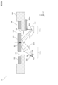
- FIG. 6 is a plan view of the second optical deflector 17 including a configuration for detecting the rotational position of the second mirror M2.
- FIG. 7 is a cross-sectional view of the second optical deflector 17 of FIG. 6 cut at position A-A by a plane parallel to the Y-Z plane.
- the outer edge of the monitor light emitted from the light source 501 is indicated by a dashed line, and the optical axis of the monitor light is indicated by a dashed line.
- the optical deflection element 100 is mounted on a frame member 200.
- the frame member 200 has a rectangular shape that is long in the X-axis direction in a plan view, and has a rectangular recess 201 into which the optical deflection element 100 fits.
- the frame member 200 has a constant thickness, and the recess 201 has a constant depth.
- the recess 201 has a rectangular opening 202 that surrounds the drive unit 102 and movable unit 103 of the optical deflection element 100 in a plan view.
- the optical deflection element 100 is mounted in the recess 201 with an adhesive or the like.
- Circuit boards 301a and 301b and support member 400 are installed on the underside of frame member 200.
- a light source 501 for emitting monitor light and a drive circuit for driving light source 501 are arranged on circuit board 301a. This drive circuit is included in mirror detection circuit 45 in FIG. 3.
- Light source 501 is formed of, for example, a light emitting diode.
- Light source 501 may also be a semiconductor laser.
- Light source 501 emits monitor light downward (negative Z-axis direction).
- the circuit board 301b is provided with a two-segment photodiode 504 and a processing circuit that processes the light receiving signal from the two-segment photodiode 504.
- This processing circuit is included in the mirror detection circuit 45 in FIG. 3.
- the two-segment photodiode 504 has two light receiving surfaces aligned in the Y-axis direction. That is, the light receiving surface of the two-segment photodiode 504 is divided into two in the Y-axis direction by a dividing line parallel to the X-axis. The two light receiving surfaces face downward (negative Z-axis direction).
- the two-segment photodiode 504 has a sensor section for each light receiving surface. These two sensor sections output light receiving signals whose magnitude corresponds to the amount of light received by the corresponding light receiving surface.
- the processing circuit described above processes these light receiving signals to generate detection signals that correspond to the rotational position of the second mirror M2.
- the configuration of the two-segment photodiode 504 and the method of generating the detection signals will be described later with reference to Figures 9(a)-(c) and 10.
- the support member 400 has a box shape with an open top.
- the support member 400 is made of a light-blocking, highly rigid material such as SUS.
- the outline of the support member 400 is the same as the outline of the frame member 200.
- the support member 400 has a rectangular recess 401 formed in a plan view. Mirrors 502 and 503 are installed in this recess 401.
- the reflecting surface 502a of the mirror 502 has a concave shape that focuses the monitor light emitted from the light source 501 on the lower surface 103a of the movable part 103.
- the reflecting surface 503a of the mirror 503 has a concave shape that focuses the reflected light of the monitor light reflected by the lower surface 103a of the movable part 103 into a focused spot.
- the light source 501, the mirrors 502, 503, and the two-segment photodiode 504 are positioned on a common plane that passes through the center of the X-axis direction of the optical deflection element 100 and is perpendicular to the rotation axis R2.
- the light source 501, the mirrors 502, 503, and the two-segment photodiode 504 are arranged so that the optical axis of the monitor light from the light source 501 to the two-segment photodiode 504 is included in this plane.
- the light source 501, mirrors 502 and 503, and two-segment photodiode 504 may be arranged on a plane parallel to the rotation axis R2 of the second mirror M2.
- the two-segment photodiode 504 is arranged so that the two light receiving surfaces are aligned in the Y-axis direction.
- the components can be arranged in the longitudinal direction of the optical deflection element 100, making it possible to reduce the overall footprint.
- Figures 8(a) and (b) are schematic diagrams showing how the reflecting surfaces 502a and 503a of the mirrors 502 and 503 are formed, respectively.
- the reflecting surface 502a of the mirror 502 has a shape that follows the shape of an ellipsoid of revolution formed by rotating an ellipse S1, which includes on its major axis L1 the light emitting point F11 of the light source 501 and the focus F12 of the monitor light set on the lower surface 103a of the movable part 103, about its major axis L1.
- a first focal length from the reflecting surface 502a to the light emitting point F11 and a second focal length from the reflecting surface 502a to the focal point F12 change according to the ratio between the major axis L1 and the minor axis of the ellipse S1.
- the ratio between the major axis L1 and the minor axis changes according to the length of the first focal length and the second focal length, and the shape of the ellipse S1 also changes.
- the shape of the ridge of the reflecting surface 502a also changes accordingly.
- the reflecting surface 503a of the mirror 503 has a shape that follows the shape of an ellipsoid of revolution formed by rotating an ellipse S2, which includes the above-mentioned focus F12 set on the lower surface 103a of the movable part 103 and the focus F13 of the monitor light on its major axis L2, about the major axis L2.
- the reflected light of the monitor light reflected by the lower surface 103a of the movable part 103 is reflected and collected by the reflecting surface 503a of the mirror 503, and focused on the focus F13.
- the focus F13 of the reflected light is positioned at a position offset from the two light receiving surfaces of the two-segment photodiode 504 in the direction perpendicular to these light receiving surfaces.
- the focus F13 is positioned on the far side of the light receiving surface of the two-segment photodiode 504 in the direction of travel of the reflected light.
- the focus F13 may also be positioned on the near side of the light receiving surface of the two-segment photodiode 504 in the direction of travel of the reflected light.
- the reflected light of the monitor light is focused on the light receiving surface of the two-segment photodiode 504 in an off-focus state.
- a focused spot of the reflected light that is larger than the focus is positioned on the two light receiving surfaces.
- the mirror 502 is also used as an optical element that focuses the monitor light emitted from the light source 501 onto the lower surface 103a of the movable part 103
- the mirror 503 is also used as an optical element that focuses the reflected light of the monitor light reflected by the lower surface 103a of the movable part 103 onto the two light receiving surfaces of the two-segment photodiode 504.
- the lower surface 103a of the movable part 103 has a reflectivity sufficient to guide a sufficient amount of reflected light to the light receiving surface of the two-segment photodiode 504.
- the area of the lower surface 103a onto which the monitor light is irradiated may be given a mirror finish, or a separate reflective film may be formed.
- Figures 9(a) to (c) are schematic diagrams showing how the focused spot SP1 moves on the light receiving surfaces Da and Db as the second mirror M2 rotates.
- the top row of Figures 9(a) to (c) shows a side view of the two-segment photodiode 504, and the bottom row of Figures 9(a) to (c) shows a plan view of the two-segment photodiode 504.
- Figure 9(a) shows the state when the second mirror M2 is near one boundary of the rotation detection range
- Figure 9(c) shows the state when the second mirror M2 is near the other boundary of the rotation detection range
- Figure 9(c) shows the state when the second mirror M2 is in the neutral position (the position in Figure 7).
- the rotation detection range refers to the range for detecting the rotation of the second mirror M2 and the movable part 103.
- the rotation detection range can be set to be slightly wider than the ideal rotation range in which the second mirror M2 and the movable part 103 rotate in the period T0 in FIG. 5.
- the two-segment photodiode 504 has two light receiving surfaces Da, Db aligned in the Y-axis direction.
- the two-segment photodiode 504 has two sensor units 504a, 504b, each of which has two light receiving surfaces Da, Db.
- the light receiving surfaces Da, Db have the same shape and size.
- the dividing line of the light receiving surfaces Da, Db is parallel to the X-axis direction.
- the focused spot SP1 of the reflected light B1 moves in the alignment direction of the light receiving surfaces Da, Db (Y-axis direction) in response to the rotation of the second mirror M2 and the movable unit 103.
- the size of the focused spot SP1 of the reflected light B1 and the size of the two light receiving surfaces Da, Db are set so that, in the above-mentioned rotation detection range, the focused spot SP1 straddles both of the two light receiving surfaces Da, Db and does not protrude from either of the light receiving surfaces Da, Db in at least the Y-axis direction.
- the size of the focused spot SP1 and the size of the two light receiving surfaces Da, Db are set so that, in the above-mentioned rotation detection range, the focused spot SP1 does not protrude from the light receiving surfaces Da, Db in not only the Y-axis direction but also the X-axis direction.
- the second mirror M2 and the movable part 103 rotate greatly in one direction, so that the focused spot SP1 of the reflected light B1 straddles the light receiving surfaces Da and Db such that the majority of the focused spot SP1 is included in the light receiving surface Da.
- the second mirror M2 and the movable part 103 rotate greatly in the other direction, so that the focused spot SP1 of the reflected light B1 straddles the light receiving surfaces Da and Db such that the majority of the focused spot SP1 is included in the light receiving surface Db.
- the state of FIG. 9(c) the second mirror M2 and the movable part 103 rotate greatly in the other direction, so that the focused spot SP1 of the reflected light B1 straddles the light receiving surfaces Da and Db such that the majority of the focused spot SP1 is included in the light receiving surface Db.
- the second mirror M2 and the movable part 103 are in a neutral position, so that the focused spot SP1 of the reflected light B1 straddles evenly the light receiving surfaces Da and Db such that half of the focused spot SP1 is included in each of the light receiving surfaces Da and Db.
- the position of the two-segment photodiode 504 is adjusted so that the focused spot SP1 falls evenly on the light receiving surfaces Da and Db when the second mirror M2 and the movable part 103 are in the neutral position.
- the extent to which the focused spot SP1 overlaps the two light receiving surfaces Da, Db changes depending on the rotational positions of the second mirror M2 and the movable part 103. Therefore, the rotational positions of the second mirror M2 and the movable part 103 can be detected by the extent to which the focused spot SP1 overlaps the two light receiving surfaces Da, Db, i.e., the balance in the magnitude of the light receiving signals output from the two sensor parts 504a, 504b.
- FIG. 10 is a graph showing a schematic relationship between the rotation angle of the second mirror M2 and the movable part 103 and the detection signal.
- the detection signal is calculated using the following formula:
- Detection signal (PD A ⁇ PD B )/(PD A +PD B ) (1)
- PD A is the magnitude of the light receiving signal output from one sensor unit 504a
- PD B is the magnitude of the light receiving signal output from the other sensor unit 504b.
- the difference between the light receiving signals PD A and PD B is divided by the sum of the light receiving signals PD A and PD B to calculate the detection signal. This makes it possible to suppress variations in the detection signal due to variations in the intensity of the reflected light B1.
- an angle of zero indicates that the second mirror M2 and the movable part 103 are in a neutral position
- the range of positive and negative angles is the range in which the second mirror M2 and the movable part 103 rotate in one direction and the other direction from the neutral position.
- the angle range in which the detection signal is parallel to the angle axis corresponds to the angle range when the focused spot SP1 is included in only one of the two light receiving surfaces Da, Db.
- the detection signal changes almost linearly in the rotation detection range from the minimum angle ⁇ min to the maximum angle ⁇ max as the rotation angle of the second mirror M2 and the movable part 103 changes. Therefore, in the rotation detection range, the rotation position of the second mirror M2 and the movable part 103 can be detected from the detection signal.
- the mirror detection circuit 45 in Fig. 3 performs amplification and noise removal processing on the light reception signals PD A and PD B output from the two sensor sections 504a and 504b of the two-segment photodiode 504.
- the mirror detection circuit 45 A/D converts the light reception signals PD A and PD B after this processing at a predetermined sampling period, and performs the calculation of the above formula (1) using the converted digital signal. In this way, the mirror detection circuit 45 sequentially outputs digital detection signals to the control section 41 at each sampling timing.
- the control unit 41 monitors the actual rotational positions of the second mirror M2 and the movable part 103 based on the graph in FIG. 10 from the received detection signal, and controls the second mirror drive circuit 43 so that the actual rotational position conforms to the ideal waveform in FIG. 5.
- the rotational position may be obtained by calculation based on the graph in FIG. 10, or may be obtained using a table that previously associates angles with the magnitude of the detection signal. In this way, the second mirror M2 and the movable part 103 rotate in an ideal rotational state.
- the detection signal is generated by the mirror detection circuit 45, but the generation of the detection signal may be performed in the control unit 41.
- the mirror detection circuit 45 is replaced with a processing circuit that performs amplification, noise removal, and A/D conversion on the light reception signals PD A and PD B output from the two sensor units 504a and 504b of the two-segment photodiode 504.
- the control unit 41 generates a detection signal from the digital light reception signals PD A and PD B input sequentially from the processing circuit by calculation of the above formula (1). Then, the control unit 41 uses this control signal to perform the above-mentioned control on the second mirror drive circuit 43.
- the focused spot SP1 moves on the two light receiving surfaces Da, Db in the arrangement direction in response to the rotation of the second mirror M2 (scanning mirror). Therefore, the balance of the extent to which the focused spot SP1 falls on the two light receiving surfaces Da, Db corresponds to the rotation position of the second mirror M2 (scanning mirror). For this reason, the two sensor sections 504a, 504b that make up the two-segment photodiode 504 each output a light receiving signal with a balance of magnitude corresponding to the rotation position of the second mirror M2 (scanning mirror). Therefore, from these two light receiving signals, a detection signal corresponding to the rotation position of the second mirror M2 (scanning mirror) can be generated using the above formula (1).
- each sensor unit 504a, 504b outputs a light receiving signal with high response. Therefore, even if the second mirror M2 (scanning mirror) is driven at high speed, a detection signal according to the rotational position of the second mirror M2 (scanning mirror) can be accurately obtained.
- the light receiving unit 500b includes a mirror 503 that reflects the reflected light of the monitor light and directs it toward the two-segment photodiode 504. In this way, the reflected light of the monitor light is turned back by the mirror 503 and directed toward the two-segment photodiode 504, so that the light receiving unit 500b can be made smaller in height. This allows the shape of the second optical deflector 17 (optical deflector) to be made compact.
- the reflecting surface 503a of the mirror 503 has a concave shape that focuses the reflected light of the monitor light on the focusing spot SP1, and the mirror 503 is also used as an optical element that focuses the reflected light of the monitor light on the two light receiving surfaces Da and Db. This allows the number of parts in the light receiving unit 500b to be reduced, and the configuration of the second optical deflector 17 (optical deflector) to be simplified.
- the projection unit 500a includes a mirror 502 (another optical element) that focuses the monitor light on the lower surface 103a of the movable unit 103, and the reflecting surface 503a of the mirror 503 on the light receiving unit 500b side has a shape along an ellipsoid of revolution formed by rotating an ellipse S2 containing the focus F12 of the monitor light on its major axis L2 about the major axis L2, as shown in FIG. 8(b), and the focus F13 of the reflected light contained on the major axis L2 is positioned at a position that is offset in a direction perpendicular to the two light receiving surfaces of the two-segment photodiode 504.
- This allows the reflected light of the monitor light reflected by the lower surface 103a of the movable unit 103 to be properly focused on the light receiving surfaces Da and Db of the two-segment photodiode 504 by the reflecting surface 503a.
- the projection unit 500a includes a light source 501 that emits monitor light, and a mirror 502 (another optical element) that focuses the monitor light emitted from the light source 501 on the lower surface 103a of the movable unit 103. This significantly reduces the area of the lower surface 103a onto which the monitor light is irradiated, allowing for greater freedom in designing the optical deflection element 100.
- the projection unit 500a includes a mirror 502 that reflects the monitor light emitted from the light source 501 and directs it toward the lower surface 103a of the movable unit 103. In this way, by turning the monitor light back at the mirror 502 and directing it toward the lower surface 103a of the movable unit 103, the projection unit 500a can be made smaller in the height direction. This allows the shape of the second optical deflector 17 (optical deflector) to be made compact.
- the reflecting surface 502a of the mirror 502 has a concave shape that focuses the monitor light on the lower surface 103a of the movable part 103, and the mirror 502 is also used as another optical element that focuses the monitor light on the lower surface 103a of the movable part 103. This reduces the number of parts in the projection part 500a and simplifies the configuration of the second optical deflector 17 (optical deflector).
- the reflecting surface 502a of the mirror 502 has a shape that follows an ellipsoid of revolution formed by rotating an ellipse S1, which includes the light emitting point F11 of the light source 501 and the focal point F12 of the monitor light on its major axis L1, about the major axis L1. This allows the monitor light emitted from the light source 501 to be properly focused on the lower surface 103a of the movable part 103.
- the projection unit 500a and the light receiving unit 500b are placed in a recess 401 of a support member 400 made of a light-shielding material, and are surrounded by the support member 400. This makes it difficult for stray light to enter the two-part photodiode 504, and makes it possible to accurately obtain a detection signal that corresponds to the rotational position of the second mirror M2.
- FIG. 11 is a cross-sectional view showing the configuration of the projection unit 500a and the light receiving unit 500b in the first modified example.
- FIG. 11 hatching is omitted for the members that make up the projection unit 500a and the light receiving unit 500b, and the support member 400 is not shown.
- the recess 401 of the support member 400 only needs to be configured to be able to support the optical members of the projection unit 500a and the light receiving unit 500b.
- the monitor light emitted from the light source 501 is irradiated onto the lower surface 103a of the movable part 103 without being focused.
- the reflected light of the monitor light reflected by the lower surface 103a of the movable part 103 is focused by the lens 511 onto the light receiving surfaces Da, Db of the two-segment photodiode 504.
- the focus F21 of the reflected light is positioned on the far side of the light receiving surfaces Da, Db in the direction of travel of the reflected light.
- the optical axis of the monitor light from the light source 501 to the two-segment photodiode 504 is included in a common plane parallel to the Y-Z plane.
- the two light receiving surfaces Da, Db are aligned in the direction in which the focused spot SP1 moves due to the rotation of the movable part 103.
- the optical axis of the reflected light passes through the dividing line of the light receiving surfaces Da, Db perpendicular to the plane including the light receiving surfaces Da, Db, as in the case of FIG. 9B.
- the focused spot SP1 moves on the two light receiving surfaces Da, Db in response to the rotation of the second mirror M2 and the movable part 103, and the extent to which the focused spot SP1 fits onto the two light receiving surfaces Da, Db changes. Therefore, as in the above embodiment, the rotation position of the second mirror M2 can be detected based on the light receiving signal output from the two-segment photodiode 504.
- FIG. 12 is a cross-sectional view showing the configuration of a projection section 500a and a light receiving section 500b according to the second modification.
- a mirror 512 is added to the configuration of the first modification.
- the mirror surface 512a of the mirror 512 is flat.
- the light source 501 is disposed on the circuit board 301a and emits monitor light downward.
- This configuration also achieves the same effect as modified example 1. Furthermore, in this configuration, the monitor light is reflected by the mirror 512 and directed to the lower surface 103a of the movable part 103, so that the projection part 500a can be made smaller in height than in the configuration of modified example 1, and the shape of the second optical deflector 17 (optical deflector) can be made more compact.
- FIG. 13 is a cross-sectional view showing the configuration of a projection section 500a and a light receiving section 500b according to the third modified example.
- a mirror 513 is added to the configuration of the second modification.
- the mirror surface 513a of the mirror 513 is flat.
- the two-segment photodiode 504 is arranged facing downward on the circuit board 301b.
- the relationship between the focused spot SP1 and the light receiving surfaces Da and Db is the same as in Figures 9(a) to (c).
- This configuration also achieves the same effects as those of modified examples 1 and 2. Furthermore, in this configuration, the reflected light of the monitor light reflected by the lower surface 103a of the movable part 103 is reflected by the mirror 513 and guided to the two-segment photodiode 504, so that the light receiving part 500b can be made smaller in height than in the configurations of modified examples 1 and 2, and the shape of the second optical deflector 17 (optical deflector) can be made more compact.
- a lens 514 is added to the configuration of the second modification.
- the lens 514 focuses the monitor light emitted from the light source 501 onto the lower surface 103a of the movable part 103.
- This configuration also achieves the same effects as the first and second modifications. Furthermore, in this configuration, the monitor light emitted from the light source 501 is focused on the lower surface 103a of the movable part 103, so the area of the lower surface 103a onto which the monitor light is irradiated can be significantly reduced. This allows for greater freedom in the design of the optical deflection element 100.
- reflected light of the monitor light occurs from the focal point of the monitor light set on the lower surface 103a. Therefore, by omitting the lens 511 and bringing the two-segment photodiode 504 closer to this focal point, it is possible to guide a relatively small focused spot SP1 to the light receiving surfaces Da, Db of the two-segment photodiode 504. As a result, as in the above embodiment, a detection signal corresponding to the rotational position of the second mirror M2 can be accurately generated from the light receiving signal from the two-segment photodiode 504.
- the lens 514 of the projection unit 500a is shared as an optical element on the light receiving unit 500b side that focuses the reflected light of the monitor light on the two light receiving surfaces Da, Db.
- the lens 511 may be omitted from the configuration of FIG. 14, and the lens 514 of the projection unit 500a may be configured to focus the monitor light on the focal point F12 instead of the lower surface 103a.
- the monitor light is irradiated onto the lower surface 103a of the movable unit 103 in an off-focus state.
- a detection signal corresponding to the rotational position of the second mirror M2 can be accurately generated from the light receiving signal from the two-segment photodiode 504.
- the lens 514 of the projection unit 500a is shared as an optical element on the light receiving unit 500b side that focuses the reflected light of the monitor light on the two light receiving surfaces Da and Db.
- the configuration of the light receiving section 500b is modified compared to the configuration in FIG. 7. That is, in the configuration in FIG. 15, the reflected light of the monitor light reflected by the lower surface 103a of the movable section 103 is focused by the lens 511 onto the light receiving surfaces Da, Db of the two-segment photodiode 504.
- the focal point F21 of the reflected light is positioned on the far side of the light receiving surfaces Da, Db in the traveling direction of the reflected light.
- this configuration also allows accurate detection of the rotation state of the second mirror M2 based on the light receiving signal from the two-segment photodiode 504. Also, as in the configuration of FIG. 14, in this configuration too, the lens 511 may be omitted and the reflected light of the monitor light may be guided directly to the light receiving surfaces Da and Db.
- FIG. 16 is a cross-sectional view showing the configuration of a projection section 500a and a light receiving section 500b according to the sixth modified example.
- the second optical deflector 17 includes a projection unit 500a that projects monitor light L11 onto the upper surface of the second mirror M2, and a light receiving unit 500b that receives the reflected light of the monitor light L11 reflected by the upper surface of the second mirror M2.
- the projection unit 500a includes a light source 501 and a mirror 502
- the light receiving unit 500b includes a mirror 503 and a two-segment photodiode 504.
- the configuration of the projection unit 500a and the light receiving unit 500b is the same as in the above embodiment, except that the projection target of the monitor light L11 (the reflection target of the monitor light L11) is the upper surface of the second mirror M2.
- the reflecting surfaces 502a, 503a of the mirrors 502, 503 are shaped along the respective ellipsoids of revolution.
- the mirrors 502, 503 focus the monitor light L11 emitted from the light source 501 near the center of the upper surface of the second mirror M2.
- the mirror 503 focuses the monitor light L11 reflected by the second mirror M2 at a position offset in the direction perpendicular to the two light receiving surfaces of the two-segment photodiode 504.
- the light source 501 and the two-segment photodiode 504 are mounted on the upper surface of the circuit board 300.
- a drive circuit for driving the light source 501 and the two-segment photodiode 504 is mounted on the circuit board 300.
- the mirrors 502 and 503 are mounted on the underside of a glass substrate 600 mounted on the support member 400.
- Light L10 for generating an image modulated by a video signal passes through the glass substrate 600 and enters the second mirror M2.
- a light shielding means 601 is provided on the underside of the glass substrate 600 in an area other than the area through which the light L10 passes.
- the focused spot SP1 moves on the two light receiving surfaces Da, Db in the arrangement direction in response to the rotation of the second mirror M2 (scanning mirror). Therefore, the balance of the coverage of the focused spot SP1 on the two light receiving surfaces Da, Db corresponds to the rotation position of the second mirror M2 (scanning mirror).
- the two sensor sections 504a, 504b constituting the two-segment photodiode 504 each output a light receiving signal with a balance of magnitude corresponding to the rotation position of the second mirror M2 (scanning mirror). Therefore, from these two light receiving signals, a detection signal corresponding to the rotation position of the second mirror M2 (scanning mirror) can be generated using the above formula (1).
- each sensor unit 504a, 504b outputs a light receiving signal with high response. Therefore, even if the second mirror M2 (scanning mirror) is driven at high speed, a detection signal according to the rotational position of the second mirror M2 (scanning mirror) can be accurately obtained.
- FIG. 18 is a cross-sectional view showing the configuration of the projection unit 500a and the light receiving unit 500b in the seventh modified example.
- the monitor light L11 emitted from the light source 501 is irradiated onto the upper surface of the second mirror M2 without being focused.
- the reflected light of the monitor light L11 reflected by the second mirror M2 is focused by the lens 511 onto the light receiving surfaces Da, Db of the two-segment photodiode 504.
- the focus F21 of the reflected light is positioned on the far side of the light receiving surfaces Da, Db in the direction of travel of the reflected light.
- the optical axis of the monitor light L11 reaching the two-segment photodiode 504 from the light source 501 is included in a common plane parallel to the Y-Z plane.
- the two light receiving surfaces Da, Db are aligned in the direction in which the focused spot SP1 moves due to the rotation of the movable part 103.
- the optical axis of the reflected light passes through the dividing line of the light receiving surfaces Da, Db perpendicular to the plane including the light receiving surfaces Da, Db, as in the case of FIG. 9B.
- the focused spot SP1 moves on the two light receiving surfaces Da, Db in response to the rotation of the second mirror M2 and the movable part 103, and the extent to which the focused spot SP1 fits onto the two light receiving surfaces Da, Db changes. Therefore, as in the above embodiment, the rotation position of the second mirror M2 can be detected based on the light receiving signal output from the two-segment photodiode 504.
- FIG. 19 is a cross-sectional view showing the configuration of a projection section 500a and a light receiving section 500b according to the eighth modified example.
- the light source 501 is omitted compared to modification example 7.
- monitor light L11 is emitted from the image generating unit 4 in FIG. 3 together with light L10 for image generation.
- the projection unit 500a includes a dichroic mirror 515, a mirror 516, and a lens 514.
- the dichroic mirror 515 reflects the monitor light L11 and transmits the light L10.
- the light L0 transmitted through the dichroic mirror 515 is incident on the second mirror M2 near the center in the Y-axis direction.
- the monitor light L11 reflected by the dichroic mirror 515 is reflected by the mirror 516 and then focused by the lens 514 near the center in the Y-axis direction of the second mirror M2.
- the configuration of the light receiving unit 500b is the same as that of the seventh modification of FIG. 18.
- the light source 501 and its drive circuit can be omitted from the second optical deflector 17. This simplifies the configuration of the second optical deflector 17.
- the monitor light L11 is also scanned by the first optical deflector 15.
- the scanning direction is parallel to the dividing line of the light receiving surfaces Da, Db in FIGS. 9(a) to 9(c). Therefore, even if the monitor light L11 is scanned by the first optical deflector 15, the focused spot SP1 moves on the two light receiving surfaces Da, Db in accordance with the rotation of the second mirror M2 and the movable part 103, and the degree to which the focused spot SP1 fits the two light receiving surfaces Da, Db changes. Therefore, as in the above embodiment, the rotation position of the second mirror M2 can be detected based on the light receiving signal output from the two-segment photodiode 504. This is also true for the ninth modified example below.
- FIG. 21 is a cross-sectional view showing the configuration of a projection section 500a and a light receiving section 500b according to the ninth modified example.
- the projection unit 500a is omitted, and a dichroic mirror 515 is added to the light receiving unit 500b.
- the projection unit that projects the monitor light L11 onto the upper surface of the second mirror M2 is composed of the light source 11d, collimator lens 12d, aperture 13d, and dichroic mirror 14d shown in FIG. 20.
- the light L10 and monitor light L11 whose optical axes are aligned by the optical system in FIG. 20, enter near the center of the second mirror M2 and are reflected by the second mirror M2.
- the dichroic mirror 515 reflects the monitor light L11 and transmits the light L10.
- the monitor light L11 reflected by the dichroic mirror 515 is focused by the lens 511 onto the light receiving surface of the two-segment photodiode 504.
- the state in which the monitor light L11 is focused on the two-segment photodiode 504 is the same as in the seventh modification.
- the configuration of modification example 9 further omits the projection unit 500a. This further simplifies the configuration of the second optical deflector 17.
- FIG. 22 is a cross-sectional view showing the configuration of a projection section 500a and a light receiving section 500b according to the tenth modification.
- a half-wave plate 517 and polarizing beam splitters 518a and 518b are added to the configuration of the eighth modification in FIG. 18.
- the polarizing beam splitters 518a and 518b are disposed in the optical path of the light L10 for generating an image, and combine and separate the monitor light L11 emitted from the light source 501 into the light L10.
- the half-wave plate 517 adjusts the polarization direction of the monitor light L11 (laser light) emitted from the light source 501 so that it becomes S-polarized with respect to the polarizing beam splitter 518a.
- the polarization direction of the light L10 becomes P-polarized with respect to the polarizing beam splitter 518a.
- the polarizing beam splitter 518a aligns the optical axis of the reflected monitor light L11 with the optical axis of the transmitted light L10.
- Light L10 and monitor light L11 whose optical axes are aligned by the polarizing beam splitter 518a, are incident on the second mirror M2 near the center in the Y-axis direction and are reflected by the second mirror M2.
- light L10 and monitor light L11 reflected by the second mirror M2 light L10 passes through the polarizing beam splitter 518b, and monitor light L11 is reflected by the polarizing beam splitter 518b.
- the monitor light L11 is then focused by the lens 511 on the light receiving surface of the two-segment photodiode 504.
- the state of focus of the monitor light L11 on the two-segment photodiode 504 is the same as in the seventh modified example above.
- the lower surface 103a of the movable part 103 is a uniform plane, but as long as the monitor light is properly reflected and received by the two-segment photodiode 504 when the movable part 103 rotates, the lower surface 103a of the movable part 103 does not have to be a uniform plane, and for example, a rib may be provided near the outer periphery of the lower surface 103a of the movable part 103.
- a rib is provided on the lower surface 103a, as in the above embodiment and modified examples 4 to 6, it is preferable to focus the monitor light on the lower surface 103a of the movable part 103 and limit the area of the lower surface 103a onto which the monitor light is irradiated as small as possible. This makes it possible to prevent the monitor light from being blocked by the rib, and increases the degree of freedom in designing the optical deflection element 100.
- the width of the light receiving surfaces Da, Db in the X-axis direction is wider than the size of the focused spot SP1 in the X-axis direction, but as long as a detection signal that changes in one direction according to the rotation angle is obtained in the rotation detection range of Figure 10, the width of the light receiving surfaces Da, Db in the X-axis direction may be smaller than the size of the focused spot SP1 in the X-axis direction.
- the shapes of the light receiving surfaces Da, Db are not limited to those shown in Figures 9(a) to (c). This is also the case in the other embodiments above.
- the configuration of the present invention is used to detect the scanning position of light in the vertical direction, but the configuration of the present invention may also be used to detect the scanning position of light in the horizontal direction.
- the configuration of the projection unit 500a and the light receiving unit 500b is applied to the first optical deflector 15. This point is similar to the other embodiments described above.
- the present invention is applied to the image generating device 3 mounted on the AR glasses 1, but the image generating device to which the present invention is applied is not limited to this.
- the present invention can be used in various devices so long as it detects the rotational position of a mirror for optical scanning.
- the configurations of the projection unit 500a and the light receiving unit 500b according to the present invention are not limited to the configurations shown in the above embodiment, modified examples 1 to 6, other embodiments, and modified examples 7 to 10, and other modifications are possible.
- the calculation formula for calculating the detection signal is also not limited to the above formula (1).
- the light receiving unit is a two-part photodiode having two light receiving surfaces aligned along a direction in which the reflected light moves as the movable part rotates; an optical element that focuses the reflected light onto the two light receiving surfaces; a size of the focused spot of the reflected light and a size of the two light receiving surfaces are set so that, within a rotation detection range for detecting the rotation of the movable part, the focused spot of the reflected light straddles both of the two light receiving surfaces and does not protrude from either of the light receiving surfaces at least in a direction in which the reflected light moves.
- An optical deflector comprising:
- the focused spot moves on the two light receiving surfaces in the alignment direction in response to the rotation of the scanning mirror. Therefore, the balance of the extent to which the focused spot falls on the two light receiving surfaces corresponds to the rotation position of the scanning mirror.
- the two sensor sections that make up the two-segment photodiode each output a light receiving signal with a balance of magnitude that corresponds to the rotation position of the scanning mirror. Therefore, a detection signal that corresponds to the rotation position of the scanning mirror can be generated from these two light receiving signals.
- the response characteristics of the photodiode are high, even if the scanning mirror is driven at high speed, each sensor section outputs a light receiving signal with high response. Therefore, even if the scanning mirror is driven at high speed, a detection signal that corresponds to the rotation position of the mirror can be accurately obtained.
- the optical element is a lens.
- An optical deflector comprising:
- This technology allows the reflected light of the monitor light to be focused onto the light receiving surface of a two-segment photodiode with a simple configuration.
- the light receiving unit further includes a mirror that reflects the reflected light toward the two-segment photodiode.
- An optical deflector comprising:
- the reflected monitor light is reflected by a mirror and directed to a two-part photodiode, making it possible to miniaturize the light receiving section in the height direction and to make the shape of the optical deflector more compact.
- the reflective surface of the mirror has a concave shape that focuses the reflected light onto the focused spot;
- the mirror is commonly used as the optical element.
- This technology reduces the number of components in the light receiving section, simplifying the structure of the optical deflector.
- the projection unit includes another optical element that focuses the monitor light near a lower surface of the movable unit or near an upper surface of the scanning mirror;
- the reflecting surface of the mirror has a shape conforming to an ellipsoid of revolution formed by rotating an ellipse, the major axis of which includes the focus of the monitor light, about the major axis;
- a focal point of the reflected light included on the long axis is positioned at a position offset from the two light receiving surfaces in a direction perpendicular to the light receiving surfaces.
- the monitor light reflected by the bottom surface of the moving part can be properly focused onto the light receiving surface of the two-segment photodiode by the reflective surface of the mirror.
- the projection unit includes: a light source that emits the monitor light; and another optical element that focuses the monitor light emitted from the light source near the lower surface of the movable part or near the upper surface of the scanning mirror.
- An optical deflector comprising:
- This technology significantly reduces the area of the underside of the moving part onto which the monitor light is irradiated, allowing greater freedom in the design of the optical deflector.
- the optical element of the projection unit is a lens. 1.
- An optical deflector comprising:
- This technology allows the monitor light to be focused near the bottom surface of the moving part with a simple configuration.
- the projection unit further includes a mirror that reflects the monitor light emitted from the light source toward a lower surface of the movable unit or an upper surface of the scanning mirror.
- An optical deflector comprising:
- the reflecting surface of the mirror has a concave shape that focuses the monitor light near the bottom surface of the movable portion or near the top surface of the scanning mirror;
- the mirror is commonly used as the other optical element.
- the reflecting surface of the mirror has a shape conforming to an ellipsoid of revolution formed by rotating an ellipse, the major axis of the ellipse including the light emitting point of the light source and the focal point of the monitor light, about the major axis;
- This technology allows the monitor light emitted from the light source to be properly focused near the bottom surface of the movable part.
- the projection unit projects monitor light onto a lower surface of the movable unit; the light receiving unit receives reflected light of the monitor light reflected on the lower surface.
- An optical deflector comprising:
- An optical deflector according to any one of the first to eleventh aspects of the present invention; a control unit that controls the optical deflector based on an output from the two-segment photodiode.
- An image generating device comprising:
- the image generating device is equipped with the optical deflector described above, so that the detection signal can be obtained accurately even when the scanning mirror is driven at high speed. Therefore, the scanning position of the light can be appropriately controlled by this detection signal.
Landscapes
- Physics & Mathematics (AREA)
- General Physics & Mathematics (AREA)
- Optics & Photonics (AREA)
- Mechanical Light Control Or Optical Switches (AREA)
Abstract
第2光偏向器(17)は、回動軸(R2)について回動する可動部(103)と、可動部(103)の上面に配置され、光を走査させるための第2ミラー(M2)(走査ミラー)と、可動部(103)の下面(103a)または第2ミラー(M2)の上面にモニタ光を投射する投射部(500a)と、下面(103a)または第2ミラー(M2)の上面で反射されたモニタ光の反射光を受光する受光部(500b)と、を備える。受光部(500b)は、可動部(103)の回動により反射光が移動する方向に沿って並ぶ2つの受光面を有する2分割フォトダイオード(504)と、反射光を2つの受光面上に集光するミラー(503)(光学素子)と、を含んでいる。
Description
本発明は、光偏向器および当該光偏向器を備えた画像生成装置に関する。
従来、映像信号により変調された光を走査させて画像を生成する画像生成装置が知られている。この装置では、たとえば、第1周期で光を水平方向に走査させつつ、第1周期より長い第2周期で光を垂直方向に走査させて、1フレーム分の画像が生成される。第1周期は映像信号の1ライン分の周期に対応し、第2周期は映像信号のフレーム周期に対応する。
この種の画像生成装置では、ミラー回動方式の光偏向器を用いて、光の走査が行われる。たとえば、MEMS(Micro Electro MechanicalSystems)ミラーが、光偏向器として用いられる。さらに、光の走査位置、すなわち走査ミラーの回動位置をモニタするための構成が用いられる。
以下の特許文献1に記載の構成では、PSD(Position Sensitive Detector)を用いて走査ミラーの回動位置がモニタされる。具体的には、走査ミラーの裏面にモニタ用の光が照射され、その反射光がPSDにより受光される。反射光の受光位置に応じた検出信号がPSDから出力される。ミラーの回動に伴い、反射光の受光位置が移動する。PSDにおける反射光の受光位置から走査ミラーの回動位置が検出される。
上述の画像生成装置では、より高精細な画像を描画するために、ミラー駆動の高速化が要求される。しかしながら、上記構成では、PSDの応答特性が比較的緩やかであるため、この応答特性を超える程度まで走査ミラーが高速駆動された場合に、正確な検出信号を得ることが困難である。したがって、この高速化の要求に対応可能なミラー回動位置の検出手法の検討が必要となる。
かかる課題に鑑み、本発明は、走査ミラーを高速で駆動させた場合も、ミラーの回動位置に応じた検出信号を正確に得ることが可能な光偏向器および画像生成装置を提供することを目的とする。
本発明の第1の態様は、光偏向器に関する。この態様に係る光偏向器は、回動軸について回動する可動部と、前記可動部の上面に配置され、光を走査させるための走査ミラーと、前記可動部の下面または前記走査ミラーの上面にモニタ光を投射する投射部と、前記下面または前記上面で反射された前記モニタ光の反射光を受光する受光部と、を備える。前記受光部は、前記可動部の回動により前記反射光が移動する方向に沿って並ぶ2つの受光面を有する2分割フォトダイオードと、前記反射光を前記2つの受光面上に集光する光学素子と、を含んでいる。前記可動部の回動を検出するための回動検出範囲において、前記反射光の集光スポットが、前記2つの受光面の両方に跨がり、且つ、何れの前記受光面からも少なくとも前記反射光が移動する方向にはみ出さないように、前記集光スポットのサイズと前記2つの受光面のサイズとが設定されている。
本態様に係る光偏向器によれば、走査ミラーの回動に応じて、集光スポットが2つの受光面上をその並び方向に移動する。したがって、2つの受光面に対する集光スポットの掛かり具合のバランスは、走査ミラーの回動位置に応じたものとなる。このため、2分割フォトダイオードを構成する2つのセンサ部からは、走査ミラーの回動位置に応じた大きさのバランスで、受光信号がそれぞれ出力される。よって、これら2つの受光信号から、走査ミラーの回動位置に応じた検出信号を生成できる。
また、フォトダイオードの応答特性は高いため、走査ミラーを高速で駆動させたとしても、各センサ部からは高レスポンスで受光信号が出力される。よって、走査ミラーを高速で駆動させた場合も、ミラーの回動位置に応じた検出信号を正確に得ることができる。
本発明の第2の態様は、画像生成装置に関する。この態様に係る画像生成装置は、上記第1の態様に係る光偏向器と、前記2分割フォトダイオードからの出力に基づいて前記光偏向器を制御する制御部と、を備える。
本態様に係る画像生成装置によれば、上記第1の態様に係る光検出器を備えるため、走査ミラーを高速で駆動させた場合も、検出信号を正確に取得できる。よって、この検出信号によって、光の走査位置を適正に制御できる。
以上のとおり、本発明によれば、走査ミラーを高速で駆動させた場合も、ミラーの回動位置に応じた検出信号を正確に得ることが可能な光偏向器および画像生成装置を提供できる。
本発明の効果ないし意義は、以下に示す実施形態の説明により更に明らかとなろう。ただし、以下に示す実施形態は、あくまでも、本発明を実施化する際の一つの例示であって、本発明は、以下の実施形態に記載されたものに何ら制限されるものではない。
ただし、図面はもっぱら説明のためのものであって、この発明の範囲を限定するものではない。
以下、本発明の実施形態について図面を参照して説明する。
以下の実施形態には、ARグラスの画像生成装置に本発明を適用した例が示されている。ただし、以下の実施形態は、本発明の一実施形態あって、本発明は、以下の実施形態に何ら制限されるものではない。たとえば、本発明は、ARグラスの画像生成装置に限らず、ARゴーグル、VRグラス、VRゴーグル、車載のヘッドアップディスプレイなどの画像生成装置にも適用可能である。
図1は、ARグラス1の構成を模式的に示す斜視図である。図1には、ARグラス1の前後左右上下方向が付記されている。
ARグラス1は、フレーム2と、一対の画像生成装置3と、を備える。一対の画像生成装置3は、左右方向に対称である。画像生成装置3は、画像生成部4と、ハーフミラー5と、検出部6と、を備える。ARグラス1は、一般的な眼鏡と同様、使用者の頭部に装着される。
フレーム2は、前面部2aおよび一対の支持部2bにより構成される。一対の支持部2bは、前面部2aの右端および左端から後方に延びている。フレーム2が使用者に装着されると、前面部2aが使用者の一対の目Eの前方に位置付けられる。前面部2aは、透明な材料(たとえば、樹脂等)により構成される。
画像生成部4は、支持部2bの内側面に設置される。画像生成部4は、対応するハーフミラー5に対して、映像信号により変調された光を投射する。
ハーフミラー5は、前面部2aの内側面に設置される。ハーフミラー5は、対応する画像生成部4から投射された光を使用者の目Eに反射するとともに、前後方向に進む光を透過する。ハーフミラー5により反射された画像生成部4からの光は、目E内の網膜の中心に位置する中心窩に照射される。これにより、使用者は、画像生成装置3により生成されたフレーム画像20(図2参照)を視覚的に把握できる。また、使用者は、ハーフミラー5を介してARグラス1の前方を見ることができるため、ARグラス1の前方の状態と、画像生成装置3により生成されたフレーム画像20とを重ねて視覚的に把握できる。
一対の検出部6は、前面部2aの内側面に設置され、一対のハーフミラー5の間に位置付けられている。検出部6は、使用者の視線を検出するために用いられる。使用者の視線検出については、追って図3を参照して説明する。
図2は、画像生成部4の構成を模式的に示す図である。
画像生成部4は、光源11a、11b、11cと、コリメータレンズ12a、12b、12cと、アパーチャ13a、13b、13cと、ミラー14aと、ダイクロイックミラー14b、14cと、第1光偏向器15と、リレー光学系16と、第2光偏向器17と、を備える。
光源11a、11b、11cは、たとえば、半導体レーザである。光源11aは、635nm以上645nm以下の範囲に含まれる赤色波長のレーザ光を出射し、光源11bは、510nm以上530nm以下の範囲に含まれる緑色波長のレーザ光を出射し、光源11cは、440nm以上460nm以下の範囲に含まれる青色波長のレーザ光を出射する。
本実施形態では、後述するフレーム画像20としてカラー画像が生成されるため、画像生成部4は、赤色、緑色および青色のレーザ光を出射可能な光源11a、11b、11cを備える。フレーム画像20として単色の画像を表示する場合、画像生成部4は、画像の色に対応する1つの光源のみを備えていてもよい。また、画像生成部4は、出射波長の異なる2つの光源を備える構成でもよい。
光源11a、11b、11cから出射された光は、それぞれ、コリメータレンズ12a、12b、12cによって平行光に変換される。コリメータレンズ12a、12b、12cを透過した光は、それぞれ、アパーチャ13a、13b、13cによって、ほぼ円形のビームに整形される。
ミラー14aは、アパーチャ13aを通過した赤色光を略全反射する。ダイクロイックミラー14bは、アパーチャ13bを通過した緑色光を反射し、ミラー14aで反射された赤色光を透過する。ダイクロイックミラー14cは、アパーチャ13cを通過した青色光を反射し、ダイクロイックミラー14bを経由した赤色光および緑色光を透過する。ミラー14aと2つのダイクロイックミラー14b、14cは、光源11a、11b、11cから出射された各色の光の光軸を整合させるように配置されている。
第1光偏向器15は、ダイクロイックミラー14cを経由した光を反射する。第1光偏向器15は、たとえば、MEMS(Micro Electro Mechanical System)ミラーである。第1光偏向器15は、ダイクロイックミラー14cを経由した光が入射する第1ミラーM1(走査ミラー)を、駆動信号に応じて、上下方向に平行な回動軸R1の周りに回動させる構成を備える。第1ミラーM1が回動することにより、光の反射方向が変化する。これにより、第1ミラーM1によって反射された光は、目Eの網膜において左右方向(水平方向)に走査される。
リレー光学系16は、第1光偏向器15によって反射された光を、第2光偏向器17の第2ミラーM2(走査ミラー)の中心へと向かわせる。すなわち、第1光偏向器15に入射する光は、第1ミラーM1によって所定の振り角で振られる。リレー光学系16は、各振り角の光を、第2ミラーM2の中心へと向かわせる。リレー光学系16は、複数のミラーを有し、第1光偏向器15によって反射された光を複数のミラーによって反射させて、第2光偏向器17に向かわせる。これにより、リレー光学系16の内部に長い光路長を実現でき、第2ミラーM2から見たときの光の振り角を抑制できる。
第2光偏向器17は、リレー光学系16を経由した光を反射する。第2光偏向器17は、MEMSミラーである。第2光偏向器17は、リレー光学系16を経由した光が入射する第2ミラーM2を、駆動信号に応じて、左右方向に平行な回動軸R2の周りに回動させる。第2ミラーM2が回動することにより、光の反射方向が変化する。これにより、目Eの網膜において、第1光偏向器15によって左右方向(水平方向)に走査される光が、上下方向(垂直方向)にも走査される。
なお、第2光偏向器17の構成は、追って、図4、図6および図7を参照して説明する。
第2光偏向器17によって反射された光、すなわち、画像生成部4から出射された光は、ハーフミラー5によって反射され、目Eの網膜においてフレーム画像20を形成する。すなわち、映像信号により変調された光(光源11a~11cから出射される光)が第1光偏向器15および第2光偏向器17により水平方向(左右方向)および垂直方向(上下方向)に走査されることで、1フレーム分のフレーム画像20が、目Eの網膜に形成される。
図3は、画像生成装置3の回路部の構成を示す図である。
検出部6は、光源61および撮像素子62を備え、画像生成部4の制御部41に接続されている。光源61は、たとえば、赤外波長の光を出射するLEDである。撮像素子62は、たとえば、CMOSイメージセンサまたはCCDイメージセンサである。光源61は、制御部41の指示に応じて使用者の目Eに光を照射する。撮像素子62は、制御部41の指示に応じて使用者の目Eを撮像し、撮像した撮像画像を制御部41に出力する。
画像生成部4は、制御部41と、第1ミラー駆動回路42と、第2ミラー駆動回路43と、レーザ駆動回路44と、ミラー検出回路45と、を備える。
制御部41は、CPUやFPGAなどの演算処理ユニットやメモリを備える。制御部41は、外部装置からの映像信号を処理して、画像生成部4の各部を制御する。また、制御部41は、検出部6からの撮像画像に基づいて、たとえば、暗瞳孔法、明瞳孔法、角膜反射法などにより、使用者の視線を検出する。制御部41は、検出した使用者の視線に基づいて、使用者の網膜に形成されるフレーム画像20における視点位置を取得する。
第1ミラー駆動回路42は、制御部41からの駆動信号に応じて、第1光偏向器15の第1ミラーM1を駆動させる。第2ミラー駆動回路43は、制御部41からの駆動信号に応じて、第2光偏向器17の第2ミラーM2を駆動させる。
ミラー検出回路45は、第2光偏向器17における第2ミラーM2の駆動状態、すなわち、垂直方向(上下方向)における光の走査位置に応じた検出信号を制御部41に出力する。ミラー検出回路45における検出信号の生成方法については、追って、図9および図10を参照して説明する。
制御部41は、ミラー検出回路45からの検出信号に基づいて、第2ミラーM2が所望の駆動波形で垂直方向(上下方向)に回動するよう、第2ミラー駆動回路43に駆動信号を出力する。また、制御部41は、検出部6により検出された使用者の視線と、ミラー検出回路45からの検出信号とに基づいて、当該視線の位置にフレーム画像20が描写されるよう、第2ミラー駆動回路43を制御する。
なお、画像生成装置3は、第1光偏向器15における第1ミラーM1の駆動状態、すなわち、水平方向(左右方向)における光の走査位置を検出する検出回路を、さらに備えてよい。この場合、制御部41は、この検出回路からの検出信号に基づいて、第1ミラーM1が所望の駆動波形で水平方向(左右方向)に回動するよう、第1ミラー駆動回路42を制御する。
図4は、第2光偏向器17に含まれる光偏向素子100の構成を示す平面図である。図4には、互いに直交するX、Y、Z軸が付記されている。X軸正方向は、図1の右方向に対応する。
図4に示すように、本実施形態では、第2光偏向器17が、ミアンダ型のMEMSミラー(光偏向素子100)を備えている。但し、光偏向素子100は、ミアンダ型のMEMSミラーに限らず、他の構成の光偏向素子であってもよい。
光偏向素子100は、支持部101と、一対の駆動部102と、可動部103と、を備える。支持部101は、所定厚みの枠状の部材であり、たとえば、シリコン基板により構成される。平面視において、支持部101は、長方形の輪郭を有する。
駆動部102は、一端が支持部101に繋がり他端が可動部103に繋がる基板110と、基板110の上面に形成された4つの圧電アクチュエータ111とを備える。基板110は、回動軸R2に垂直な方向に蛇行するミアンダ形状を有する。基板110の厚みは一定である。基板110は、支持部101と同様の材料によって支持部101と一体形成される。
4つの圧電アクチュエータ111は、回動軸R2に垂直な方向(Y軸方向)に延びる基板110の4つの領域110aの上面にそれぞれ配置される。圧電アクチュエータ111は、一定厚みの圧電体が上部電極と下部電極とに挟まれた構成である。
圧電体は、たとえば、PZT(チタン酸ジルコン酸鉛)により形成される。上部電極および下部電極は、たとえば、白金により形成される。上部電極と下部電極との間に電圧(駆動信号)が印加されることにより、圧電アクチュエータ111(圧電体)が伸縮する。これにより、基板110が撓み、可動部103を駆動させるための駆動力が生じる。
可動部103は、一対の駆動部102によって支持されている。可動部103は、駆動部102の基板110と同様の材料によって、基板110および支持部101と一体形成される。平面視において可動部103は、円形である。可動部103の形状が、正方形等の他の形状であってもよい。可動部103の厚みは、基板110と同様の厚みである。したがって、可動部103は、円板形状を有する。可動部103の上面に、上述の第2ミラーM2が形成される。可動部103上面の反射率が高い場合、可動部103の上面が第2ミラーM2となっていてもよい。
可動部103側から奇数番目の圧電アクチュエータ111に同位相の駆動電圧が印加されると、これら圧電アクチュエータ111の圧電体が変形し、奇数番目の基板110(領域110a)が撓むように振動する。このとき、可動部103側から偶数番目の圧電アクチュエータ111に、奇数番目の圧電アクチュエータ111に印加する駆動電圧とは逆位相の駆動電圧が印加される。これにより、圧電アクチュエータ111内の圧電体が変形し、偶数番目の基板110(領域110a)が撓むように変形する。こうして、それぞれの基板110が変形することにより、可動部103が回動軸R2について回動する。
図5は、圧電アクチュエータ111に印加される駆動電圧の一例を示すグラフである。
上記のように、奇数番目の圧電アクチュエータ111に図5の駆動電圧が印加される場合、偶数番目の圧電アクチュエータ111には図5と逆相の駆動電圧が印加される。図5において、横軸は時間であり、縦軸は電圧である。縦軸および横軸は、それぞれ規格化されている。
図5において、T0は、駆動電圧の1周期である。すなわち、この周期T0で、第2ミラーM2が反復回動する。この周期T0のうち、期間ΔTが画像の描画期間である。すなわち、期間ΔTにおいて、映像信号により変調された光を光源11a~11cが出射し、画像描画のための垂直走査が第2ミラーM2により行われる。
図5の波形では、駆動電圧波形を急峻に変化させている。すなわち、部分的に第2ミラーM2の走査速度が変化されている。これにより、部分的に描画数が増減する。第2ミラーM2の走査速度が遅い期間において、第2ミラーM2の走査方向の描画数が増加する。この期間は、視線を含む走査範囲に対応する。したがって、フレーム画像20は、視線を含む範囲の密度が高められ、使用者はより明瞭に画像を見ることができる。
ところで、上記構成の画像生成装置3では、垂直方向における光の走査位置、すなわち、第2光偏向器17における第2ミラーM2(走査ミラー)の回動位置をモニタするための構成が用いられる。これにより、適切な描画位置でミラーの走査速度を調整することができる。この場合、たとえば、可動部103の裏面(Z軸負側の面)にモニタ用の光を照射し、その反射光をPSDにより受光する構成を用いることができる。
しかしながら、この構成では、PSDの応答特性が比較的緩やかであるため、この応答特性を超える高い周波数成分を含む駆動電圧波形で第2ミラーM2(走査ミラー)の急峻な速度制御を行った場合に、正確な検出信号を得ることが困難となる。たとえば、第2ミラーM2を100kHz程度の高い周波数成分を含む駆動電圧波形で制御した場合、図5に破線の丸で示す駆動電圧の切り替わりタイミングにおいて、PSDからの検出信号が丸みを帯びてしまう。上記構成の画像生成装置3では、より高精細な画像を描画するために、第2ミラーM2を急峻(たとえば、100kHz程度)に速度制御することが要求される。
そこで、本実施形態では、この高速化の要求に対応可能な回動位置の検出手法が用いられる。
図6は、第2ミラーM2の回動位置を検出するための構成を含む第2光偏向器17の平面図である。また、図7は、図6の第2光偏向器17をA-A位置においてY-Z平面に平行な平面で切断したときの断面図である。図7には、光源501から出射されたモニタ光の外縁が破線で示され、モニタ光の光軸が一点鎖線で示されている。
図6および図7に示すように、光偏向素子100は、枠部材200に設置される。枠部材200は、平面視においてX軸方向に長い長方形の形状を有し、光偏向素子100が嵌まる長方形の凹部201を有する。枠部材200の厚みは一定であり、凹部201の深さは一定である。凹部201には、平面視において光偏向素子100の駆動部102および可動部103を囲む長方形の開口202が形成されている。光偏向素子100は、接着剤等によって、凹部201に設置される。
枠部材200の下面に、回路基板301a、301bと、支持部材400とが設置される。回路基板301aには、モニタ光を出射するための光源501と、光源501を駆動するための駆動回路が配置されている。この駆動回路は、図3のミラー検出回路45に含まれる。光源501は、たとえば発光ダイオードにより構成される。光源501が、半導体レーザであってもよい。光源501は、下方向(Z軸負方向)にモニタ光を出射する。
回路基板301bには、2分割フォトダイオード504と、2分割フォトダイオード504からの受光信号を処理する処理回路が配置されている。この処理回路は、図3のミラー検出回路45に含まれる。2分割フォトダイオード504は、Y軸方向に並ぶ2つの受光面を備える。すなわち、2分割フォトダイオード504の受光面は、X軸に平行な分割線によってY軸方向に2つに分割されている。2つの受光面は、下方向(Z軸負方向)を向いている。
2分割フォトダイオード504は、受光面ごとにセンサ部を有する。これら2つのセンサ部から、対応する受光面の受光光量に応じた大きさの受光信号が出力される。上述の処理回路は、これら受光信号を処理して、第2ミラーM2の回動位置に応じた検出信号を生成する。2分割フォトダイオード504の構成および検出信号の生成方法については、追って、図9(a)~(c)および図10を参照して説明する。
支持部材400は、上部が開放された箱形状を有する。支持部材400は、SUS等の遮光性かつ高剛性の材料から構成される。平面視において、支持部材400の輪郭は、枠部材200の輪郭と同じである。支持部材400には、平面視において矩形の凹部401が形成されている。この凹部401に、ミラー502、503が設置されている。
ミラー502の反射面502aは、光源501から出射されたモニタ光を可動部103の下面103aに合焦させる凹形状を有している。ミラー503の反射面503aは、可動部103の下面103aで反射されたモニタ光の反射光を集光スポットに集光させる凹形状を有している。光源501、ミラー502、503および2分割フォトダイオード504は、光偏向素子100のX軸方向の中心を通り、回動軸R2に垂直な共通の平面上に位置づけられる。すなわち、光源501から2分割フォトダイオード504へと至るモニタ光の光軸がこの平面に含まれるように、光源501、ミラー502、503および2分割フォトダイオード504が配置される。
なお、この配置は一例であり、たとえば、光源501、ミラー502、503および2分割フォトダイオード504は、第2ミラーM2の回動軸R2に平行な平面上に配置してもよい。この場合も、2分割フォトダイオード504は、2つの受光面がY軸方向に並ぶように配置される。この構成では、光偏向素子100の長手方向に部品を配置できるため、全体のフットプリントを小さくできる。
図8(a)、(b)は、それぞれ、ミラー502、503の反射面502a、503aの形成方法を模式的に示す図である。
図8(a)に示すように、ミラー502の反射面502aは、光源501の発光点F11と、可動部103の下面103aに設定されたモニタ光の焦点F12とを長軸L1上に含む楕円S1を、長軸L1について回転させて形成される回転楕円面に沿った形状を有する。
図8(a)に示すように、反射面502aの1つの稜線が楕円S1の一部に沿う形状である場合、楕円S1の長軸L1上にある発光点F11から発した光は、反射面502aによって、長軸L1上の焦点F12に合焦される。逆に、焦点F12から発した光は、反射面502aによって、発光点F11に合焦される。
ここで、楕円S1の長軸L1と短軸との比に応じて、反射面502aから発光点F11までの第1焦点距離と、反射面502aから焦点F12までの第2焦点距離とが変化する。換言すると、第1焦点距離と第2焦点距離の長さに応じて、長軸L1と短軸の比が変化し、楕円S1の形状も変化する。これに応じて、反射面502aの稜線の形状も変化する。
ここでは、発光点F11に光源501の発光点が設定され、焦点F12が可動部103の下面103aに設定される。これにより、光源501から出射されたモニタ光は、ミラー502の反射面502aにより反射および集光されて、可動部103の下面103aに合焦される。モニタ光の焦点F12は、たとえば、可動部103の下面103aの中心に設定される。
図8(b)に示すように、ミラー503の反射面503aは、可動部103の下面103aに設定された上述の焦点F12と、モニタ光の焦点F13とを長軸L2上に含む楕円S2を、長軸L2について回転させて形成される回転楕円面に沿った形状を有する。これにより、上記と同様の原理により、可動部103の下面103aで反射されたモニタ光の反射光は、ミラー503の反射面503aにより反射および集光されて、焦点F13に合焦される。
ここで、反射光の焦点F13は、2分割フォトダイオード504の2つの受光面に対して、これら受光面に垂直な方向に外れた位置に位置づけられる。図8(b)の例では、2分割フォトダイオード504の受光面に対して反射光の進行方向の奥側に、焦点F13が位置づけられている。2分割フォトダイオード504の受光面に対して反射光の進行方向の手前側に、焦点F13が位置づけられてもよい。すなわち、モニタ光の反射光は、オフフォーカスの状態で2分割フォトダイオード504の受光面に集光される。これにより、焦点より大き目の反射光の集光スポットが、2つの受光面上に位置づけられる。
図7の構成では、光源501およびミラー502が、可動部103の下面103aにモニタ光を投射する投射部500aを構成し、ミラー503および2分割フォトダイオード504が、可動部103の下面103aで反射されたモニタ光の反射光を受光する受光部500bを構成する。また、ミラー502は、光源501から出射されたモニタ光を可動部103の下面103aに合焦させる光学素子に共用され、ミラー503は、可動部103の下面103aで反射されたモニタ光の反射光を2分割フォトダイオード504の2つの受光面上に集光する光学素子に共用されている。
なお、図7の構成において、可動部103の下面103aは、2分割フォトダイオード504の受光面に十分な光量の反射光を導き得る程度の反射率を有することが想定されている。これに対し、2分割フォトダイオード504の受光面に十分な光量の反射光を導き得えない場合は、モニタ光が照射される下面103aの領域に鏡面仕上げが施され、あるいは、別途、反射膜が形成されてもよい。
図7の構成において、可動部103とともに第2ミラーM2が回動軸R2について回動すると、2分割フォトダイオード504の受光面上に集光された反射光の集光スポットが、Y軸方向、すなわち、2つの受光面の並び方向に移動する。したがって、第2ミラーM2の回動位置に応じて、2つの受光面に対する集光スポットの掛かり具合が変化する。
図9(a)~(c)は、第2ミラーM2の回動に伴い集光スポットSP1が受光面Da、Db上を移動する様子を模式的に示す図である。図9(a)~(c)の上段には、2分割フォトダイオード504を側方から見た図が示され、図9(a)~(c)の下段には、2分割フォトダイオード504を平面視した図が示されている。
図9(a)は、第2ミラーM2が、回動検出範囲の一方の境界付近にあるときの状態を示し、図9(c)は、第2ミラーM2が、回動検出範囲の他方の境界付近にあるときの状態を示している。図9(c)は、第2ミラーM2が中立位置(図7の位置)にあるときの状態を示している。
ここで、回動検出範囲とは、第2ミラーM2および可動部103の回動を検出するための範囲のことである。回動検出範囲は、図5の周期T0において第2ミラーM2および可動部103が回動する理想の回動範囲よりやや広めに設定され得る。
図9(a)~(c)に示すように、2分割フォトダイオード504は、Y軸方向に並ぶ2つの受光面Da、Dbを有する。2分割フォトダイオード504は、2つの受光面Da、Dbをそれぞれ有する2つのセンサ部504a、504bを備えている。受光面Da、Dbの形状およびサイズは、互いに等しい。受光面Da、Dbの分割線は、X軸方向に平行である。反射光B1の集光スポットSP1は、第2ミラーM2および可動部103の回動に応じて、受光面Da、Dbの並び方向(Y軸方向)に移動する。
上述の回動検出範囲において、反射光B1の集光スポットSP1が、2つの受光面Da、Dbの両方に跨がり、且つ、何れの受光面Da、Dbから少なくともY軸方向にはみ出さないように、集光スポットSP1のサイズと2つの受光面Da、Dbのサイズとが設定されている。図9(a)~(c)の例では、上述の回動検出範囲において、Y軸方向のみならずX軸方向にも、集光スポットSP1が受光面Da、Dbからはみ出さないように、集光スポットSP1のサイズと2つの受光面Da、Dbのサイズとが設定されている。
図9(a)の状態では、第2ミラーM2および可動部103が一方向に大きく回動しているため、反射光B1の集光スポットSP1は、その大部分が受光面Daに含まれるように、受光面Da、Dbに跨がる。図9(c)の状態では、第2ミラーM2および可動部103が他方向に大きく回動しているため、反射光B1の集光スポットSP1は、その大部分が受光面Dbに含まれるように、受光面Da、Dbに跨がる。図9(b)の状態では、第2ミラーM2および可動部103が中立位置にあるため、反射光B1の集光スポットSP1は、その半分が受光面Da、Dbにそれぞれ含まれるように、受光面Da、Dbに均等に跨がる。
2分割フォトダイオード504は、第2ミラーM2および可動部103が中立位置にあるときに、集光スポットSP1が受光面Da、Dbに均等に掛かるように、位置調整されている。
このように、第2ミラーM2および可動部103の回動位置に応じて、2つの受光面Da、Dbに対する集光スポットSP1の掛かり具合が変化する。したがって、2つの受光面Da、Dbに対する集光スポットSP1の掛かり具合、すなわち、2つのセンサ部504a、504bから出力される受光信号の大きさのバランスにより、第2ミラーM2および可動部103の回動位置を検出できる。
図10は、第2ミラーM2および可動部103の回動角度と検出信号との関係を模式的に示すグラフである。
ここでは、検出信号が、以下の式により算出される。
検出信号=(PDA-PDB)/(PDA+PDB) …(1)
式(1)において、PDAは、一方のセンサ部504aから出力される受光信号の大きさであり、PDBは、他方のセンサ部504bから出力される受光信号の大きさである。ここでは、受光信号PDA、PDBの差分が、受光信号PDA、PDBの合計で除算されて、検出信号が算出される。これにより、反射光B1の強度ばらつきにより検出信号がばらつくことを抑制できる。
図10において、角度ゼロは、第2ミラーM2および可動部103が中立位置にあることを示し、角度が正負の範囲は、第2ミラーM2および可動部103が中立位置から一方向および他方向に回動する範囲である。検出信号が角度の軸に平行である角度範囲は、集光スポットSP1が2つの受光面Da、Dbの何れか一方のみに含まれるときの角度範囲に対応する。
図10に示すように、検出信号は、最小角度θminから最大角度θmaxまでの回動検出範囲において、第2ミラーM2および可動部103の回動角度の変化に伴い、ほぼリニアに変化する。よって、回動検出範囲において、検出信号から第2ミラーM2および可動部103の回動位置を検出できる。
図3のミラー検出回路45は、2分割フォトダイオード504の2つのセンサ部504a、504bからそれぞれ出力される受光信号PDA、PDBに対して、増幅およびノイズ除去の処理を施す。ミラー検出回路45は、この処理を施した後の受光信号PDA、PDBを、所定のサンプリング周期でA/D変換し、変換後のデジタル信号を用いて、上記式(1)の演算を行う。こうして、ミラー検出回路45は、サンプリングタイミングごとに、順次、デジタルの検出信号を制御部41に出力する。
制御部41は、受信した検出信号から、図10のグラフに基づき、第2ミラーM2および可動部103の実際の回動位置をモニタし、実際の回動位置が図5の理想波形に沿うように、第2ミラー駆動回路43を制御する。回動位置の取得は、図10のグラフに基づく演算処理により行われてよく、あるいは、角度と検出信号の大きさとを予め対応づけたテーブルを用いて行われてもよい。こうして、第2ミラーM2および可動部103が、理想の回動状態で回動する。
なお、図3の構成では、ミラー検出回路45により検出信号が生成されたが、検出信号の生成が制御部41において行われてもよい。この場合、ミラー検出回路45は、2分割フォトダイオード504の2つのセンサ部504a、504bからそれぞれ出力される受光信号PDA、PDBに対して、増幅およびノイズ除去と、A/D変換とを施す処理回路に置き換えられる。制御部41は、処理回路から順次入力されるデジタルの受光信号PDA、PDBから、上記式(1)の演算により、検出信号を生成する。そして、制御部41は、この制御信号を用いて、第2ミラー駆動回路43に対する上述の制御を行う。
<実施形態の効果>
上記実施形態によれば、以下の効果が奏される。
上記実施形態によれば、以下の効果が奏される。
図9(a)~(c)に示したように、第2ミラーM2(走査ミラー)の回動に応じて、集光スポットSP1が2つの受光面Da、Db上をその並び方向に移動する。したがって、2つの受光面Da、Dbに対する集光スポットSP1の掛かり具合のバランスは、第2ミラーM2(走査ミラー)の回動位置に応じたものとなる。このため、2分割フォトダイオード504を構成する2つのセンサ部504a、504bからは、第2ミラーM2(走査ミラー)の回動位置に応じた大きさのバランスで、受光信号がそれぞれ出力される。よって、これら2つの受光信号から、上記式(1)により、第2ミラーM2(走査ミラー)の回動位置に応じた検出信号を生成できる。
また、2分割フォトダイオード504の応答特性は高いため、第2ミラーM2(走査ミラー)を高速で駆動させたとしても、各センサ部504a、504bからは高レスポンスで受光信号が出力される。よって、第2ミラーM2(走査ミラー)を高速で駆動させた場合も、第2ミラーM2(走査ミラー)の回動位置に応じた検出信号を正確に取得できる。
図7に示したように、受光部500bは、モニタ光の反射光を反射して2分割フォトダイオード504へと向かわせるミラー503を備える。このように、モニタ光の反射光をミラー503で折り返して2分割フォトダイオード504に導くことにより、受光部500bを高さ方向に小型化できる。よって、第2光偏向器17(光偏向器)の形状をコンパクトにできる。
図7に示したように、ミラー503の反射面503aは、モニタ光の反射光を集光スポットSP1に集光させる凹形状を有し、ミラー503は、モニタ光の反射光を2つの受光面Da、Db上に集光する光学素子として共用される。これにより、受光部500bの部品点数を削減でき、第2光偏向器17(光偏向器)の構成を簡素化できる。
図7に示したように、投射部500aは、モニタ光を可動部103の下面103aに合焦させるミラー502(他の光学素子)を含み、受光部500b側のミラー503の反射面503aは、図8(b)に示したように、モニタ光の焦点F12を長軸L2上に含む楕円S2を長軸L2について回転させて形成される回転楕円面に沿った形状を有し、長軸L2上に含まれる反射光の焦点F13が、2分割フォトダイオード504の2つの受光面に対して、これら受光面に垂直な方向に外れた位置に位置づけられる。これにより、可動部103の下面103aで反射されたモニタ光の反射光を反射面503aにより2分割フォトダイオード504の受光面Da、Dbに適正に集光させることができる。
図7に示したように、投射部500aは、モニタ光を出射する光源501と、光源501から出射されたモニタ光を可動部103の下面103aに合焦させるミラー502(他の光学素子)と、を含む。これにより、モニタ光が照射される下面103aの領域を顕著に小さくでき、光偏向素子100の設計の自由度を高めることができる。
図7に示したように、投射部500aは、光源501から出射されたモニタ光を反射して可動部103の下面103aに向かわせるミラー502を備える。このように、モニタ光をミラー502で折り返して可動部103の下面103aに導くことにより、投射部500aを高さ方向に小型化できる。よって、第2光偏向器17(光偏向器)の形状をコンパクトにできる。
図7に示したように、ミラー502の反射面502aは、モニタ光を可動部103の下面103aに合焦させる凹形状を有し、ミラー502は、モニタ光を可動部103の下面103aに合焦させる他の光学素子として共用される。これにより、投射部500aの部品点数を削減でき、第2光偏向器17(光偏向器)の構成の簡素化できる。
図8(a)に示したように、ミラー502の反射面502aは、光源501の発光点F11とモニタ光の焦点F12とを長軸L1上に含む楕円S1を長軸L1について回転させて形成される回転楕円面に沿った形状を有する。これにより、光源501から出射されたモニタ光を可動部103の下面103aに適正に集光させることができる。
図6および図7に示したように、投射部500aおよび受光部500bは、遮光性の材料から構成された支持部材400の凹部401に設置され、周囲が支持部材400によって囲まれる。このため、迷光が2分割フォトダイオード504に入射しにくくなり、第2ミラーM2の回転位置に応じた検出信号を精度良く取得できる。
<変更例1>
投射部500aおよび受光部500bの構成は、上記実施形態の構成に限られるものではなく、種々の変更が可能である。
投射部500aおよび受光部500bの構成は、上記実施形態の構成に限られるものではなく、種々の変更が可能である。
図11は、変更例1に係る、投射部500aおよび受光部500bの構成を示す断面図である。
便宜上、図11では、投射部500aおよび受光部500bを構成する部材には、ハッチングが省略され、支持部材400の図示が省略されている。支持部材400の凹部401は、投射部500aおよび受光部500bの各光学部材を支持可能に構成されればよい。これらの点は、変更例2以降においても同様である。
変更例1では、光源501から出射されたモニタ光は、集光されることなく可動部103の下面103aに照射される。可動部103の下面103aで反射されたモニタ光の反射光は、レンズ511によって、2分割フォトダイオード504の受光面Da、Db上に集光される。反射光の焦点F21は、受光面Da、Dbに対して反射光の進行方向の奥側に位置づけられる。光源501から2分割フォトダイオード504へと至るモニタ光の光軸は、Y-Z平面に平行な共通の平面に含まれる。2つの受光面Da、Dbは、可動部103の回動により集光スポットSP1が移動する方向に並んでいる。可動部103が中立位置にあるとき、反射光の光軸は、図9(b)の場合と同様、受光面Da、Dbを含む平面に垂直に、受光面Da、Dbの分割線を貫く。
この構成によっても、図9(a)~(c)と同様、第2ミラーM2および可動部103の回動に応じて、集光スポットSP1が、2つの受光面Da、Db上を移動し、2つの受光面Da、Dbに対する集光スポットSP1の掛かり具合が変化する。よって、上記実施形態と同様、2分割フォトダイオード504から出力される受光信号に基づいて、第2ミラーM2の回動位置を検出することができる。
<変更例2>
図12は、変更例2に係る、投射部500aおよび受光部500bの構成を示す断面図である。
図12は、変更例2に係る、投射部500aおよび受光部500bの構成を示す断面図である。
変更例2では、変更例1の構成にミラー512が追加されている。ミラー512のミラー面512aは、平面である。上記実施形態と同様、光源501は、回路基板301aに配置されて、下向きにモニタ光を出射する。
この構成によっても、変更例1と同様の効果が奏される。さらに、この構成では、モニタ光がミラー512で折り返されて可動部103の下面103aに導かれるため、変更例1の構成に比べて、投射部500aを高さ方向に小型化でき、第2光偏向器17(光偏向器)の形状をコンパクトにできる。
<変更例3>
図13は、変更例3に係る、投射部500aおよび受光部500bの構成を示す断面図である。
図13は、変更例3に係る、投射部500aおよび受光部500bの構成を示す断面図である。
変更例3では、変更例2の構成にミラー513が追加されている。ミラー513のミラー面513aは、平面である。上記実施形態と同様、2分割フォトダイオード504は、回路基板301bに下向きに配置されている。集光スポットSP1と受光面Da、Dbとの関係は、図9(a)~(c)と同様である。
この構成によっても、変更例1、2と同様の効果が奏される。さらに、この構成では、可動部103の下面103aで反射されたモニタ光の反射光がミラー513で折り返されて2分割フォトダイオード504に導かれるため、変更例1、2の構成に比べて、受光部500bを高さ方向に小型化でき、第2光偏向器17(光偏向器)の形状をコンパクトにできる。
<変更例4>
図14は、変更例4に係る、投射部500aおよび受光部500bの構成を示す断面図である。
図14は、変更例4に係る、投射部500aおよび受光部500bの構成を示す断面図である。
変更例4では、変更例2の構成にレンズ514が追加されている。レンズ514は、光源501から出射されたモニタ光を、可動部103の下面103aに合焦させる。
この構成によっても、変更例1、2と同様の効果が奏される。さらに、この構成では、光源501から出射されたモニタ光が可動部103の下面103aに合焦されるため、モニタ光が照射される下面103aの領域を顕著に小さくできる。よって、光偏向素子100の設計の自由度を高めることができる。
なお、図14の構成では、下面103aに設定されたモニタ光の焦点からモニタ光の反射光が生じる。このため、レンズ511を省略して、2分割フォトダイオード504をこの焦点に接近させることにより、比較的小さな集光スポットSP1を2分割フォトダイオード504の受光面Da、Dbに導くことができる。これにより、上記実施形態と同様、2分割フォトダイオード504からの受光信号から、第2ミラーM2の回動位置に応じた検出信号を正確に生成できる。この場合、投射部500aのレンズ514が、モニタ光の反射光を2つの受光面Da、Db上に集光する受光部500b側の光学素子として共用されることになる。
また、図14の構成からレンズ511を省略し、投射部500aのレンズ514が、モニタ光を下面103aではなく、焦点F12に合焦させるように構成されてもよい。この場合、モニタ光は、オフフォーカスの状態で可動部103の下面103aに照射される。この構成によっても、2分割フォトダイオード504からの受光信号から、第2ミラーM2の回動位置に応じた検出信号を正確に生成できる。また、この場合も、投射部500aのレンズ514が、モニタ光の反射光を2つの受光面Da、Db上に集光する受光部500b側の光学素子として共用されることになる。
<変更例5>
図15は、変更例5に係る、投射部500aおよび受光部500bの構成を示す断面図である。
図15は、変更例5に係る、投射部500aおよび受光部500bの構成を示す断面図である。
変更例5では、図7の構成に比べて、受光部500bの構成が変更されている。すなわち、図15の構成では、可動部103の下面103aで反射されたモニタ光の反射光は、レンズ511によって、2分割フォトダイオード504の受光面Da、Dbに集光される。反射光の焦点F21は、受光面Da、Dbに対して、反射光の進行方向の奥側に位置づけられる。
この構成によっても、上記実施形態と同様、2分割フォトダイオード504からの受光信号に基づいて、第2ミラーM2の回動状態を正確に検出できる。また、この構成においても、図14の構成の場合と同様、レンズ511を省略して、モニタ光の反射光を直接、受光面Da、Dbに導くようにしてもよい。
<変更例6>
図16は、変更例6に係る、投射部500aおよび受光部500bの構成を示す断面図である。
図16は、変更例6に係る、投射部500aおよび受光部500bの構成を示す断面図である。
変更例6では、図7の構成に比べて、投射部500aの構成が変更されている。すなわち、図16の構成では、光源501から出射されたモニタ光は、レンズ514によって、可動部103の下面103aに合焦される。この構成によっても、上記実施形態と同様、2分割フォトダイオード504からの受光信号に基づいて、第2ミラーM2の回動状態を正確に検出できる。
<他の実施形態>
上記実施形態では、投射部500aが可動部103の下面103aにモニタ光を投射したが、モニタ光が第2ミラーM2の上面に投射されてもよい。
上記実施形態では、投射部500aが可動部103の下面103aにモニタ光を投射したが、モニタ光が第2ミラーM2の上面に投射されてもよい。
図17は、他の実施形態に係る、第2光偏向器17の構成を示す断面図である。
図17に示すように、第2光偏向器17は、第2ミラーM2の上面にモニタ光L11を投射する投射部500aと、第2ミラーM2の上面で反射されたモニタ光L11の反射光を受光する受光部500bとを備える。上記実施形態と同様、投射部500aは、光源501とミラー502とを備え、受光部500bは、ミラー503と2分割フォトダイオード504とを備える。
投射部500aおよび受光部500bの構成は、モニタ光L11の投射対象(モニタ光L11の反射対象)が第2ミラーM2の上面であることを除いて、上記実施形態と同様である。上記実施形態と同様、ミラー502、503の反射面502a、503aは、それぞれの回転楕円面に沿った形状である。ミラー502、503は、光源501から出射されたモニタ光L11を第2ミラーM2の上面の中心付近に集光させる。ミラー503は、第2ミラーM2で反射されたモニタ光L11を、2分割フォトダイオード504の2つの受光面に対して、これら受光面に垂直な方向に外れた位置に集光させる。
光源501および2分割フォトダイオード504は、回路基板300の上面に設置されている。回路基板300には、光源501および2分割フォトダイオード504を駆動するための駆動回路が実装されている。ミラー502、503は、支持部材400に設置されたガラス基板600の下面に設置されている。映像信号により変調された画像生成用の光L10は、ガラス基板600を透過して、第2ミラ-M2に入射する。ガラス基板600の下面には、光L10が透過する領域以外の領域に、遮光手段601が設けられている。
図17の構成によっても、上記実施形態と同様、第2ミラーM2(走査ミラー)の回動に応じて、集光スポットSP1が2つの受光面Da、Db上をその並び方向に移動する。したがって、2つの受光面Da、Dbに対する集光スポットSP1の掛かり具合のバランスは、第2ミラーM2(走査ミラー)の回動位置に応じたものとなる。このため、2分割フォトダイオード504を構成する2つのセンサ部504a、504bからは、第2ミラーM2(走査ミラー)の回動位置に応じた大きさのバランスで、受光信号がそれぞれ出力される。よって、これら2つの受光信号から、上記式(1)により、第2ミラーM2(走査ミラー)の回動位置に応じた検出信号を生成できる。
また、2分割フォトダイオード504の応答特性は高いため、第2ミラーM2(走査ミラー)を高速で駆動させたとしても、各センサ部504a、504bからは高レスポンスで受光信号が出力される。よって、第2ミラーM2(走査ミラー)を高速で駆動させた場合も、第2ミラーM2(走査ミラー)の回動位置に応じた検出信号を正確に取得できる。
<変更例7>
上記他の実施形態において、投射部500aおよび受光部500bの構成は、上記の構成に限られるものではなく、種々の変更が可能である。
上記他の実施形態において、投射部500aおよび受光部500bの構成は、上記の構成に限られるものではなく、種々の変更が可能である。
図18は、変更例7に係る、投射部500aおよび受光部500bの構成を示す断面図である。
変更例7では、光源501から出射されたモニタ光L11は、集光されることなく第2ミラーM2の上面に照射される。第2ミラーM2で反射されたモニタ光L11の反射光は、レンズ511によって、2分割フォトダイオード504の受光面Da、Db上に集光される。反射光の焦点F21は、受光面Da、Dbに対して反射光の進行方向の奥側に位置づけられる。光源501から2分割フォトダイオード504へと至るモニタ光L11の光軸は、Y-Z平面に平行な共通の平面に含まれる。2つの受光面Da、Dbは、可動部103の回動により集光スポットSP1が移動する方向に並んでいる。可動部103が中立位置にあるとき、反射光の光軸は、図9(b)の場合と同様、受光面Da、Dbを含む平面に垂直に、受光面Da、Dbの分割線を貫く。
この構成によっても、図9(a)~(c)と同様、第2ミラーM2および可動部103の回動に応じて、集光スポットSP1が、2つの受光面Da、Db上を移動し、2つの受光面Da、Dbに対する集光スポットSP1の掛かり具合が変化する。よって、上記実施形態と同様、2分割フォトダイオード504から出力される受光信号に基づいて、第2ミラーM2の回動位置を検出することができる。
<変更例8>
図19は、変更例8に係る、投射部500aおよび受光部500bの構成を示す断面図である。
図19は、変更例8に係る、投射部500aおよび受光部500bの構成を示す断面図である。
変更例8では、変更例7に比べて、光源501が省略されている。ここでは、モニタ光L11が、画像生成用の光L10とともに、図3の画像生成部4から出射される。
すなわち、図20に示すように、モニタ光L11を出射するための光源11dと、光源11dから出射されたモニタ光L11の平行光化およびビーム整形のためのコリメータレンズ12dおよびアパーチャ13dと、モニタ光L11の光軸を、光源11a~11cからの光L10の光軸に整合させるためのダイクロイックミラー14dとが、図3の構成に追加される。光源11dは、赤外の波長帯のレーザ光を出射する。ダイクロイックミラー14dは、光源11dからのモニタ光L11を反射し、光源11a~11cからの光L10を透過する。
図19に戻って、投射部500aは、ダイクロイックミラー515と、ミラー516と、レンズ514とを備える。ダイクロイックミラー515は、図20の光学系により光軸が整合された光L10およびモニタ光L11のうち、モニタ光L11を反射し、光L10を透過させる。ダイクロイックミラー515を透過したL0は、第2ミラーM2のY軸方向の中心付近に入射する。ダイクロイックミラー515で反射されたモニタ光L11は、ミラー516で反射された後、レンズ514で第2ミラーM2のY軸方向の中心付近に集光される。受光部500bの構成は、図18の変更例7と同様である。
変更例8の構成によれば、第2光偏向器17から光源501と、その駆動回路を省略できる。よって、第2光偏向器17の構成を簡素にできる。
なお、変更例8の構成では、第1光偏向器15によってモニタ光L11も走査される。しかし、その走査方向は、図9(a)~(c)における受光面Da、Dbの分割線に平行な方向となる。したがって、第1光偏向器15によってモニタ光L11が走査されても、第2ミラーM2および可動部103の回動に応じて、集光スポットSP1が、2つの受光面Da、Db上を移動し、2つの受光面Da、Dbに対する集光スポットSP1の掛かり具合が変化する。よって、上記実施形態と同様、2分割フォトダイオード504から出力される受光信号に基づいて、第2ミラーM2の回動位置を検出することができる。この点は、以下の変更例9についても同様である。
<変更例9>
図21は、変更例9に係る、投射部500aおよび受光部500bの構成を示す断面図である。
図21は、変更例9に係る、投射部500aおよび受光部500bの構成を示す断面図である。
変更例9では、変更例8に比べて、投射部500aが省略され、受光部500bにダイクロイックミラー515が追加されている。モニタ光L11を第2ミラーM2の上面に投射する投射部は、図20に示した光源11d、コリメータレンズ12d、アパーチャ13dおよびダイクロイックミラー14dにより構成される。図20の光学系により光軸が整合された光L10およびモニタ光L11は、第2ミラーM2の中央付近に入射し、第2ミラーM2で反射される。ダイクロイックミラー515は、第2ミラーM2で反射された光L10およびモニタ光L11のうち、モニタ光L11を反射し、光L10を透過させる。
ダイクロイックミラー515で反射されたモニタ光L11は、レンズ511によって2分割フォトダイオード504の受光面に集光される。2分割フォトダイオード504に対するモニタ光L11の集光状態は、上記変更例7と同様である。
変更例9の構成によれば、変更例8の構成に比べて、さらに、投射部500aを省略できる。よって、第2光偏向器17の構成をさらに簡素にできる。
<変更例10>
図22は、変更例10に係る、投射部500aおよび受光部500bの構成を示す断面図である。
図22は、変更例10に係る、投射部500aおよび受光部500bの構成を示す断面図である。
変更例10では、図18の変更例18の構成に、1/2波長板517と、偏光ビームスプリッタ518a、518bとが追加されている。偏光ビームスプリッタ518a、518bは、画像生成用の光L10の光路に配置され、光源501から出射されたモニタ光L11を、光L10に統合および分離させる。1/2波長板517は、光源501から出射されたモニタ光L11(レーザ光)の偏光方向を、偏光ビームスプリッタ518aに対してS偏光となるよう調整する。光L10の偏光方向は、偏光ビームスプリッタ518aに対してP偏光となっている。偏光ビームスプリッタ518aは、反射したモニタ光L11の光軸を、透過した光L10の光軸に整合させる。
偏光ビームスプリッタ518aによって光軸が整合された光L10およびモニタ光L11は、第2ミラーM2のY軸方向の中心付近に入射し、第2ミラーM2で反射される。第2ミラーM2で反射された光L10およびモニタ光L11のうち、光L10は、偏光ビームスプリッタ518bを透過し、モニタ光L11は、偏光ビームスプリッタ518bで反射される。その後、モニタ光L11は、レンズ511によって2分割フォトダイオード504の受光面に集光される。2分割フォトダイオード504に対するモニタ光L11の集光状態は、上記変更例7と同様である。
<その他の変更例>
上記実施形態では、光源501から出射されたモニタ光を可動部103の下面103aに合焦させたが、必ずしも、モニタ光を下面103aに厳密に合焦させなくてもよく、モニタ光を下面103a付近に合焦させてもよい。たとえば、モニタ光の焦点を、下面103aに対して下面103aに垂直な方向にややずれた位置に設定し、オフフォーカスの状態でモニタ光を可動部103の下面103aに照射してもよい。このことは、変更例4~6においても同様である。また、他の実施形態および変更例7~10についても同様に、モニタ光を第2ミラーM2の上面に厳密に合焦させなくてもよく、モニタ光を第2ミラーM2の上面付近に合焦させてもよい。
上記実施形態では、光源501から出射されたモニタ光を可動部103の下面103aに合焦させたが、必ずしも、モニタ光を下面103aに厳密に合焦させなくてもよく、モニタ光を下面103a付近に合焦させてもよい。たとえば、モニタ光の焦点を、下面103aに対して下面103aに垂直な方向にややずれた位置に設定し、オフフォーカスの状態でモニタ光を可動部103の下面103aに照射してもよい。このことは、変更例4~6においても同様である。また、他の実施形態および変更例7~10についても同様に、モニタ光を第2ミラーM2の上面に厳密に合焦させなくてもよく、モニタ光を第2ミラーM2の上面付近に合焦させてもよい。
また、上記実施形態および変更例1~6では、可動部103の下面103aは一様な平面であったが、可動部103の回動時にモニタ光が適正に反射されて2分割フォトダイオード504に受光される限り、可動部103の下面103aが一様な平面でなくてもよく、たとえば、可動部103の下面103aの外周付近にリブが設けられてもよい。下面103aにリブが設けられる場合は、上記実施形態および変更例4~6のように、モニタ光を可動部103の下面103aに集光させて、モニタ光が照射される下面103aの領域をなるべく小さく制限することが好ましい。これにより、リブによりモニタ光が遮光されることを抑制でき、光偏向素子100の設計の自由度を高めることができる。
また、上記実施形態では、図9(a)~(c)に示すように、受光面Da、DbのX軸方向の幅が集光スポットSP1のX福方向のサイズより広かったが、図10の回動検出範囲において回動角に応じて一方向に変化する検出信号が得られれば、受光面Da、DbのX軸方向の幅が集光スポットSP1のX軸方向のサイズより小さくてもよい。受光面Da、Dbの形状も図9(a)~(c)に示した形状に限られない。この点は、上記他の実施形態においても同様である。
また、上記実施形態では、垂直方向における光の走査位置の検出のために本発明の構成が用いられたが、水平方向における光の走査位置の検出のために本発明の構成が用いられてもよい。この場合、第1光偏向器15に対して、投射部500aおよび受光部500bの構成が適用される。この点は、上記他の実施形態においても同様である。
また、上記実施形態では、ARグラス1に搭載される画像生成装置3に本発明を適用した例を示したが、本発明が適用される画像生成装置は、これに限られるものではない。本発明は、光走査用のミラーの回動位置を検出する限りにおいて、種々の装置に用いられ得る。本発明に係る投射部500aおよび受光部500bの構成も、上記実施形態、変更例1~6、他の実施形態および変更例7~10に示した構成に限られるものではなく、さらに他の変更が可能である。検出信号を算出するための算出式も、上記式(1)に限られるものではない。
本発明の実施形態は、特許請求の範囲に示された技術的思想の範囲内において、適宜、種々の変更が可能である。
(付記)
以上の実施形態の記載により、下記の技術が開示される。
以上の実施形態の記載により、下記の技術が開示される。
(技術1)
回動軸について回動する可動部と、
前記可動部の上面に配置され、光を走査させるための走査ミラーと、
前記可動部の下面または前記走査ミラーの上面にモニタ光を投射する投射部と、
前記下面または前記上面で反射された前記モニタ光の反射光を受光する受光部と、を備え、
前記受光部は、
前記可動部の回動により前記反射光が移動する方向に沿って並ぶ2つの受光面を有する2分割フォトダイオードと、
前記反射光を前記2つの受光面上に集光する光学素子と、を含み、
前記可動部の回動を検出するための回動検出範囲において、前記反射光の集光スポットが、前記2つの受光面の両方に跨がり、且つ、何れの前記受光面からも少なくとも前記反射光が移動する方向にはみ出さないように、前記集光スポットのサイズと前記2つの受光面のサイズとが設定されている、
ことを特徴とする光偏向器。
この技術によれば、走査ミラーの回動に応じて、集光スポットが2つの受光面上をその並び方向に移動する。したがって、2つの受光面に対する集光スポットの掛かり具合のバランスは、走査ミラーの回動位置に応じたものとなる。このため、2分割フォトダイオードを構成する2つのセンサ部からは、走査ミラーの回動位置に応じた大きさのバランスで、受光信号がそれぞれ出力される。よって、これら2つの受光信号から、走査ミラーの回動位置に応じた検出信号を生成できる。また、フォトダイオードの応答特性は高いため、走査ミラーを高速で駆動させたとしても、各センサ部からは高レスポンスで受光信号が出力される。よって、走査ミラーを高速で駆動させた場合も、ミラーの回動位置に応じた検出信号を正確に得ることができる。
(技術2)
技術1に記載の光偏向器において、
前記光学素子は、レンズである、
ことを特徴とする光偏向器。
技術1に記載の光偏向器において、
前記光学素子は、レンズである、
ことを特徴とする光偏向器。
この技術によれば、簡易な構成により、モニタ光の反射光を2分割フォトダイオードの受光面に集光させることができる。
(技術3)
技術1に記載の光偏向器において、
前記受光部は、前記反射光を反射して前記2分割フォトダイオードへと向かわせるミラーをさらに備える、
ことを特徴とする光偏向器。
技術1に記載の光偏向器において、
前記受光部は、前記反射光を反射して前記2分割フォトダイオードへと向かわせるミラーをさらに備える、
ことを特徴とする光偏向器。
この技術によれば、モニタ光の反射光がミラーで折り返されて2分割フォトダイオードに導かれるため、受光部を高さ方向に小型化でき、光偏向器の形状をコンパクトにできる。
(技術4)
技術3に記載の光偏向器において、
前記ミラーの反射面は、前記反射光を前記集光スポットに集光させる凹形状を有し、
前記ミラーは、前記光学素子として共用される、
ことを特徴とする光偏向器。
技術3に記載の光偏向器において、
前記ミラーの反射面は、前記反射光を前記集光スポットに集光させる凹形状を有し、
前記ミラーは、前記光学素子として共用される、
ことを特徴とする光偏向器。
この技術によれば、受光部の部品点数を削減できるため、光偏向器の構成を簡素化できる。
(技術5)
技術4に記載の光偏向器において、
前記投射部は、前記モニタ光を前記可動部の下面付近または前記走査ミラーの上面付近に合焦させる他の光学素子を含み、
前記ミラーの反射面は、前記モニタ光の焦点を長軸上に含む楕円を前記長軸について回転させて形成される回転楕円面に沿った形状を有し、
前記長軸上に含まれる前記反射光の焦点が、前記2つの受光面に対して、これら受光面に垂直な方向に外れた位置に位置づけられる、
ことを特徴とする光偏向器。
技術4に記載の光偏向器において、
前記投射部は、前記モニタ光を前記可動部の下面付近または前記走査ミラーの上面付近に合焦させる他の光学素子を含み、
前記ミラーの反射面は、前記モニタ光の焦点を長軸上に含む楕円を前記長軸について回転させて形成される回転楕円面に沿った形状を有し、
前記長軸上に含まれる前記反射光の焦点が、前記2つの受光面に対して、これら受光面に垂直な方向に外れた位置に位置づけられる、
ことを特徴とする光偏向器。
この技術によれば、可動部の下面で反射されたモニタ光の反射光を、ミラーの反射面により、2分割フォトダイオードの受光面に適正に集光させることができる。
(技術6)
技術1ないし5の何れかに記載の光偏向器において、
前記投射部は、
前記モニタ光を出射する光源と、
前記光源から出射された前記モニタ光を前記可動部の下面付近または前記走査ミラーの上面付近に合焦させる他の光学素子と、を含む、
ことを特徴とする光偏向器。
技術1ないし5の何れかに記載の光偏向器において、
前記投射部は、
前記モニタ光を出射する光源と、
前記光源から出射された前記モニタ光を前記可動部の下面付近または前記走査ミラーの上面付近に合焦させる他の光学素子と、を含む、
ことを特徴とする光偏向器。
この技術によれば、モニタ光が照射される可動部の下面の領域を顕著に小さくでき、光偏向器の設計の自由度を高めることができる。
(技術7)
技術6に記載の光偏向器において、
前記投射部の前記光学素子は、レンズである、
ことを特徴とする光偏向器。
技術6に記載の光偏向器において、
前記投射部の前記光学素子は、レンズである、
ことを特徴とする光偏向器。
この技術によれば、簡易な構成により、モニタ光を可動部の下面付近に合焦させることができる。
(技術8)
技術6に記載の光偏向器において、
前記投射部は、前記光源から出射された前記モニタ光を反射して前記可動部の下面または前記走査ミラーの上面に向かわせるミラーをさらに備える、
ことを特徴とする光偏向器。
技術6に記載の光偏向器において、
前記投射部は、前記光源から出射された前記モニタ光を反射して前記可動部の下面または前記走査ミラーの上面に向かわせるミラーをさらに備える、
ことを特徴とする光偏向器。
この技術によれば、光源から出射されたモニタ光が、投射部のミラーで折り返されて可動部の下面に導かれるため、投射部を高さ方向に小型化でき、光偏向器の形状をコンパクトにできる。
(技術9)
技術8に記載の光偏向器において、
前記ミラーの反射面は、前記モニタ光を前記可動部の下面付近または前記走査ミラーの上面付近に合焦させる凹形状を有し、
前記ミラーは、前記他の光学素子として共用される、
ことを特徴とする光偏向器。
技術8に記載の光偏向器において、
前記ミラーの反射面は、前記モニタ光を前記可動部の下面付近または前記走査ミラーの上面付近に合焦させる凹形状を有し、
前記ミラーは、前記他の光学素子として共用される、
ことを特徴とする光偏向器。
この技術によれば、投射部の部品点数を削減できるため、光偏向器の構成の簡素化できる。
(技術10)
技術9に記載の光偏向器において、
前記ミラーの反射面は、前記光源の発光点と前記モニタ光の焦点とを長軸上に含む楕円を前記長軸について回転させて形成される回転楕円面に沿った形状を有する、
ことを特徴とする光偏向器。
技術9に記載の光偏向器において、
前記ミラーの反射面は、前記光源の発光点と前記モニタ光の焦点とを長軸上に含む楕円を前記長軸について回転させて形成される回転楕円面に沿った形状を有する、
ことを特徴とする光偏向器。
この技術によれば、光源から出射されたモニタ光を可動部の下面付近に適正に合焦させることができる。
(技術11)
技術1に記載の光偏向器において、
前記投射部は、前記可動部の下面にモニタ光を投射し、
前記受光部は、前記下面で反射された前記モニタ光の反射光を受光する、
ことを特徴とする光偏向器。
技術1に記載の光偏向器において、
前記投射部は、前記可動部の下面にモニタ光を投射し、
前記受光部は、前記下面で反射された前記モニタ光の反射光を受光する、
ことを特徴とする光偏向器。
(技術12)
技術1ないし11の何れか1つに記載の光偏向器と、
前記2分割フォトダイオードからの出力に基づいて前記光偏向器を制御する制御部と、を備える、
ことを特徴とする画像生成装置。
技術1ないし11の何れか1つに記載の光偏向器と、
前記2分割フォトダイオードからの出力に基づいて前記光偏向器を制御する制御部と、を備える、
ことを特徴とする画像生成装置。
この技術によれば、画像生成装置が上述の光偏向器を備えるため、走査ミラーを高速で駆動させた場合も、検出信号を正確に取得できる。よって、この検出信号によって、光の走査位置を適正に制御できる。
3 画像生成装置
11d 光源
17 第2光偏向器
41 制御部
103 可動部
103a 下面
500a 投射部
500b 受光部
501 光源
502 ミラー(他の光学素子)
502a 反射面
503 ミラー(光学素子)
503a 反射面
504 2分割フォトダイオード
504a、504b センサ部
511 レンズ(光学素子)
512、513 ミラー
514 レンズ(他の光学素子)
M2 第2ミラー(走査ミラー)
Da、Db 受光面
L1、L2 長軸
S1、S2 楕円
F11 発光点
F12、F13 焦点
B1 反射光
SP1 集光スポット
11d 光源
17 第2光偏向器
41 制御部
103 可動部
103a 下面
500a 投射部
500b 受光部
501 光源
502 ミラー(他の光学素子)
502a 反射面
503 ミラー(光学素子)
503a 反射面
504 2分割フォトダイオード
504a、504b センサ部
511 レンズ(光学素子)
512、513 ミラー
514 レンズ(他の光学素子)
M2 第2ミラー(走査ミラー)
Da、Db 受光面
L1、L2 長軸
S1、S2 楕円
F11 発光点
F12、F13 焦点
B1 反射光
SP1 集光スポット
Claims (12)
- 回動軸について回動する可動部と、
前記可動部の上面に配置され、光を走査させるための走査ミラーと、
前記可動部の下面または前記走査ミラーの上面にモニタ光を投射する投射部と、
前記下面または前記上面で反射された前記モニタ光の反射光を受光する受光部と、を備え、
前記受光部は、
前記可動部の回動により前記反射光が移動する方向に沿って並ぶ2つの受光面を有する2分割フォトダイオードと、
前記反射光を前記2つの受光面上に集光する光学素子と、を含み、
前記可動部の回動を検出するための回動検出範囲において、前記反射光の集光スポットが、前記2つの受光面の両方に跨がり、且つ、何れの前記受光面からも少なくとも前記反射光が移動する方向にはみ出さないように、前記集光スポットのサイズと前記2つの受光面のサイズとが設定されている、
ことを特徴とする光偏向器。
- 請求項1に記載の光偏向器において、
前記光学素子は、レンズである、
ことを特徴とする光偏向器。
- 請求項1に記載の光偏向器において、
前記受光部は、前記反射光を反射して前記2分割フォトダイオードへと向かわせるミラーをさらに備える、
ことを特徴とする光偏向器。
- 請求項3に記載の光偏向器において、
前記ミラーの反射面は、前記反射光を前記集光スポットに集光させる凹形状を有し、
前記ミラーは、前記光学素子として共用される、
ことを特徴とする光偏向器。
- 請求項4に記載の光偏向器において、
前記投射部は、前記モニタ光を前記可動部の下面付近または前記走査ミラーの上面付近に合焦させる他の光学素子を含み、
前記ミラーの反射面は、前記モニタ光の焦点を長軸上に含む楕円を前記長軸について回転させて形成される回転楕円面に沿った形状を有し、
前記長軸上に含まれる前記反射光の焦点が、前記2つの受光面に対して、これら受光面に垂直な方向に外れた位置に位置づけられる、
ことを特徴とする光偏向器。
- 請求項1に記載の光偏向器において、
前記投射部は、
前記モニタ光を出射する光源と、
前記光源から出射された前記モニタ光を前記可動部の下面付近または前記走査ミラーの上面付近に合焦させる他の光学素子と、を含む、
ことを特徴とする光偏向器。
- 請求項6に記載の光偏向器において、
前記投射部の前記光学素子は、レンズである、
ことを特徴とする光偏向器。
- 請求項6に記載の光偏向器において、
前記投射部は、前記光源から出射された前記モニタ光を反射して前記可動部の下面または前記走査ミラーの上面に向かわせるミラーをさらに備える、
ことを特徴とする光偏向器。
- 請求項8に記載の光偏向器において、
前記ミラーの反射面は、前記モニタ光を前記可動部の下面付近または前記走査ミラーの上面付近に合焦させる凹形状を有し、
前記ミラーは、前記他の光学素子として共用される、
ことを特徴とする光偏向器。
- 請求項9に記載の光偏向器において、
前記ミラーの反射面は、前記光源の発光点と前記モニタ光の焦点とを長軸上に含む楕円を前記長軸について回転させて形成される回転楕円面に沿った形状を有する、
ことを特徴とする光偏向器。
- 請求1に記載の光偏向器において、
前記投射部は、前記可動部の下面にモニタ光を投射し、
前記受光部は、前記下面で反射された前記モニタ光の反射光を受光する、
ことを特徴とする光偏向器。
- 請求項1ないし11の何れか一項に記載の光偏向器と、
前記2分割フォトダイオードからの出力に基づいて前記光偏向器を制御する制御部と、を備える、
ことを特徴とする画像生成装置。
Applications Claiming Priority (2)
| Application Number | Priority Date | Filing Date | Title |
|---|---|---|---|
| JP2023-098149 | 2023-06-14 | ||
| JP2023098149 | 2023-06-14 |
Publications (1)
| Publication Number | Publication Date |
|---|---|
| WO2024257739A1 true WO2024257739A1 (ja) | 2024-12-19 |
Family
ID=93852012
Family Applications (1)
| Application Number | Title | Priority Date | Filing Date |
|---|---|---|---|
| PCT/JP2024/021108 Ceased WO2024257739A1 (ja) | 2023-06-14 | 2024-06-10 | 光偏向器および画像生成装置 |
Country Status (1)
| Country | Link |
|---|---|
| WO (1) | WO2024257739A1 (ja) |
Citations (6)
| Publication number | Priority date | Publication date | Assignee | Title |
|---|---|---|---|---|
| US4564757A (en) * | 1982-09-30 | 1986-01-14 | Burroughs Corporation | Mirror position sensor for improved track selection in optical data disk system |
| JP2004053503A (ja) * | 2002-07-23 | 2004-02-19 | Olympus Corp | 偏向角検出装置 |
| JP2006195083A (ja) * | 2005-01-12 | 2006-07-27 | Sharp Corp | 光走査装置 |
| JP2010117353A (ja) * | 2008-11-14 | 2010-05-27 | Berkin Bv | コリオリ型流量センサシステム |
| JP2014006299A (ja) * | 2012-06-21 | 2014-01-16 | Olympus Corp | 角度検出装置および走査型顕微鏡システム |
| CN112859048A (zh) * | 2019-11-27 | 2021-05-28 | 上海禾赛科技股份有限公司 | 光束扫描装置、包括其的激光雷达和控制方法 |
-
2024
- 2024-06-10 WO PCT/JP2024/021108 patent/WO2024257739A1/ja not_active Ceased
Patent Citations (6)
| Publication number | Priority date | Publication date | Assignee | Title |
|---|---|---|---|---|
| US4564757A (en) * | 1982-09-30 | 1986-01-14 | Burroughs Corporation | Mirror position sensor for improved track selection in optical data disk system |
| JP2004053503A (ja) * | 2002-07-23 | 2004-02-19 | Olympus Corp | 偏向角検出装置 |
| JP2006195083A (ja) * | 2005-01-12 | 2006-07-27 | Sharp Corp | 光走査装置 |
| JP2010117353A (ja) * | 2008-11-14 | 2010-05-27 | Berkin Bv | コリオリ型流量センサシステム |
| JP2014006299A (ja) * | 2012-06-21 | 2014-01-16 | Olympus Corp | 角度検出装置および走査型顕微鏡システム |
| CN112859048A (zh) * | 2019-11-27 | 2021-05-28 | 上海禾赛科技股份有限公司 | 光束扫描装置、包括其的激光雷达和控制方法 |
Similar Documents
| Publication | Publication Date | Title |
|---|---|---|
| EP2793080B1 (en) | Automatic-focus projection system | |
| JP5281923B2 (ja) | 投射型表示装置 | |
| US20080151185A1 (en) | Retinal scanning image display apparatus and image display system | |
| JP3277776B2 (ja) | 放射温度計の照準装置 | |
| JP6663045B2 (ja) | レーザ機械加工中にプロセス監視するためのデバイスであって光学式間隔測定装置とプリズム偏光ユニットで構成されるデバイス、並びに、当該デバイスを搭載したレーザ加工ヘッド | |
| JP7302592B2 (ja) | 情報検出装置、映像投影装置、情報検出方法、及び映像投影方法 | |
| CN110832380B (zh) | 用于校准数据眼镜的投影装置的方法以及用于执行方法的数据眼镜的投影装置 | |
| JP7230443B2 (ja) | 距離測定装置及び移動体 | |
| CN116457717A (zh) | 用于智能眼镜的光学装置 | |
| WO2001059505A1 (en) | Laser condensing apparatus and laser machining apparatus | |
| JP7163230B2 (ja) | 視線検出装置、視線検出方法、及び表示装置 | |
| KR101428864B1 (ko) | 초점 위치 변경 장치 및 이를 이용한 공초점 광학 장치 | |
| US20250314877A1 (en) | Method and system for using characterization light to detect fiber position in a fiber scanning projector | |
| US20030142086A1 (en) | Image projecting device | |
| US20150253130A1 (en) | Device for generating an optical dot pattern | |
| US20220299759A1 (en) | Light deflector, image projection apparatus, and distance-measuring apparatus | |
| WO2024257739A1 (ja) | 光偏向器および画像生成装置 | |
| WO2018179860A1 (ja) | レーザモジュール及び画像投影装置 | |
| JPH06265773A (ja) | 顕微鏡自動焦点装置 | |
| JP4590916B2 (ja) | 画像表示装置 | |
| US20240353533A1 (en) | Distance measurement device | |
| JP4589931B2 (ja) | 小型光走査装置 | |
| US12607846B2 (en) | Reflector device for emitting a plurality of reflected beams from a single main light beam | |
| JP2926777B2 (ja) | 形状計測装置 | |
| JPH08334309A (ja) | 光学式変位検出装置 |
Legal Events
| Date | Code | Title | Description |
|---|---|---|---|
| 121 | Ep: the epo has been informed by wipo that ep was designated in this application |
Ref document number: 24823355 Country of ref document: EP Kind code of ref document: A1 |
|
| NENP | Non-entry into the national phase |
Ref country code: DE |