WO2024257745A1 - Rare earth sintered magnet - Google Patents
Rare earth sintered magnet Download PDFInfo
- Publication number
- WO2024257745A1 WO2024257745A1 PCT/JP2024/021127 JP2024021127W WO2024257745A1 WO 2024257745 A1 WO2024257745 A1 WO 2024257745A1 JP 2024021127 W JP2024021127 W JP 2024021127W WO 2024257745 A1 WO2024257745 A1 WO 2024257745A1
- Authority
- WO
- WIPO (PCT)
- Prior art keywords
- rare earth
- atomic
- earth sintered
- sintered magnet
- magnet
- Prior art date
- Legal status (The legal status is an assumption and is not a legal conclusion. Google has not performed a legal analysis and makes no representation as to the accuracy of the status listed.)
- Ceased
Links
Images
Classifications
-
- H—ELECTRICITY
- H01—ELECTRIC ELEMENTS
- H01F—MAGNETS; INDUCTANCES; TRANSFORMERS; SELECTION OF MATERIALS FOR THEIR MAGNETIC PROPERTIES
- H01F1/00—Magnets or magnetic bodies characterised by the magnetic materials therefor; Selection of materials for their magnetic properties
- H01F1/01—Magnets or magnetic bodies characterised by the magnetic materials therefor; Selection of materials for their magnetic properties of inorganic materials
- H01F1/03—Magnets or magnetic bodies characterised by the magnetic materials therefor; Selection of materials for their magnetic properties of inorganic materials characterised by their coercivity
- H01F1/032—Magnets or magnetic bodies characterised by the magnetic materials therefor; Selection of materials for their magnetic properties of inorganic materials characterised by their coercivity of hard-magnetic materials
- H01F1/04—Magnets or magnetic bodies characterised by the magnetic materials therefor; Selection of materials for their magnetic properties of inorganic materials characterised by their coercivity of hard-magnetic materials metals or alloys
- H01F1/047—Alloys characterised by their composition
- H01F1/053—Alloys characterised by their composition containing rare earth metals
- H01F1/055—Alloys characterised by their composition containing rare earth metals and magnetic transition metals, e.g. SmCo5
- H01F1/057—Alloys characterised by their composition containing rare earth metals and magnetic transition metals, e.g. SmCo5 and IIIa elements, e.g. Nd2Fe14B
- H01F1/0571—Alloys characterised by their composition containing rare earth metals and magnetic transition metals, e.g. SmCo5 and IIIa elements, e.g. Nd2Fe14B in the form of particles, e.g. rapid quenched powders or ribbon flakes
- H01F1/0575—Alloys characterised by their composition containing rare earth metals and magnetic transition metals, e.g. SmCo5 and IIIa elements, e.g. Nd2Fe14B in the form of particles, e.g. rapid quenched powders or ribbon flakes pressed, sintered or bonded together
- H01F1/0577—Alloys characterised by their composition containing rare earth metals and magnetic transition metals, e.g. SmCo5 and IIIa elements, e.g. Nd2Fe14B in the form of particles, e.g. rapid quenched powders or ribbon flakes pressed, sintered or bonded together sintered
-
- B—PERFORMING OPERATIONS; TRANSPORTING
- B22—CASTING; POWDER METALLURGY
- B22F—WORKING METALLIC POWDER; MANUFACTURE OF ARTICLES FROM METALLIC POWDER; MAKING METALLIC POWDER; APPARATUS OR DEVICES SPECIALLY ADAPTED FOR METALLIC POWDER
- B22F3/00—Manufacture of workpieces or articles from metallic powder characterised by the manner of compacting or sintering; Apparatus specially adapted therefor ; Presses and furnaces
- B22F3/10—Sintering only
-
- C—CHEMISTRY; METALLURGY
- C22—METALLURGY; FERROUS OR NON-FERROUS ALLOYS; TREATMENT OF ALLOYS OR NON-FERROUS METALS
- C22C—ALLOYS
- C22C38/00—Ferrous alloys, e.g. steel alloys
-
- C—CHEMISTRY; METALLURGY
- C22—METALLURGY; FERROUS OR NON-FERROUS ALLOYS; TREATMENT OF ALLOYS OR NON-FERROUS METALS
- C22C—ALLOYS
- C22C38/00—Ferrous alloys, e.g. steel alloys
- C22C38/001—Ferrous alloys, e.g. steel alloys containing N
-
- C—CHEMISTRY; METALLURGY
- C22—METALLURGY; FERROUS OR NON-FERROUS ALLOYS; TREATMENT OF ALLOYS OR NON-FERROUS METALS
- C22C—ALLOYS
- C22C38/00—Ferrous alloys, e.g. steel alloys
- C22C38/002—Ferrous alloys, e.g. steel alloys containing In, Mg, or other elements not provided for in one single group C22C38/001 - C22C38/60
-
- C—CHEMISTRY; METALLURGY
- C22—METALLURGY; FERROUS OR NON-FERROUS ALLOYS; TREATMENT OF ALLOYS OR NON-FERROUS METALS
- C22C—ALLOYS
- C22C38/00—Ferrous alloys, e.g. steel alloys
- C22C38/005—Ferrous alloys, e.g. steel alloys containing rare earths, i.e. Sc, Y, Lanthanides
-
- C—CHEMISTRY; METALLURGY
- C22—METALLURGY; FERROUS OR NON-FERROUS ALLOYS; TREATMENT OF ALLOYS OR NON-FERROUS METALS
- C22C—ALLOYS
- C22C38/00—Ferrous alloys, e.g. steel alloys
- C22C38/06—Ferrous alloys, e.g. steel alloys containing aluminium
-
- C—CHEMISTRY; METALLURGY
- C22—METALLURGY; FERROUS OR NON-FERROUS ALLOYS; TREATMENT OF ALLOYS OR NON-FERROUS METALS
- C22C—ALLOYS
- C22C38/00—Ferrous alloys, e.g. steel alloys
- C22C38/10—Ferrous alloys, e.g. steel alloys containing cobalt
-
- C—CHEMISTRY; METALLURGY
- C22—METALLURGY; FERROUS OR NON-FERROUS ALLOYS; TREATMENT OF ALLOYS OR NON-FERROUS METALS
- C22C—ALLOYS
- C22C38/00—Ferrous alloys, e.g. steel alloys
- C22C38/14—Ferrous alloys, e.g. steel alloys containing titanium or zirconium
-
- C—CHEMISTRY; METALLURGY
- C22—METALLURGY; FERROUS OR NON-FERROUS ALLOYS; TREATMENT OF ALLOYS OR NON-FERROUS METALS
- C22C—ALLOYS
- C22C38/00—Ferrous alloys, e.g. steel alloys
- C22C38/16—Ferrous alloys, e.g. steel alloys containing copper
-
- H—ELECTRICITY
- H01—ELECTRIC ELEMENTS
- H01F—MAGNETS; INDUCTANCES; TRANSFORMERS; SELECTION OF MATERIALS FOR THEIR MAGNETIC PROPERTIES
- H01F1/00—Magnets or magnetic bodies characterised by the magnetic materials therefor; Selection of materials for their magnetic properties
- H01F1/01—Magnets or magnetic bodies characterised by the magnetic materials therefor; Selection of materials for their magnetic properties of inorganic materials
- H01F1/03—Magnets or magnetic bodies characterised by the magnetic materials therefor; Selection of materials for their magnetic properties of inorganic materials characterised by their coercivity
- H01F1/032—Magnets or magnetic bodies characterised by the magnetic materials therefor; Selection of materials for their magnetic properties of inorganic materials characterised by their coercivity of hard-magnetic materials
- H01F1/04—Magnets or magnetic bodies characterised by the magnetic materials therefor; Selection of materials for their magnetic properties of inorganic materials characterised by their coercivity of hard-magnetic materials metals or alloys
- H01F1/047—Alloys characterised by their composition
- H01F1/053—Alloys characterised by their composition containing rare earth metals
- H01F1/055—Alloys characterised by their composition containing rare earth metals and magnetic transition metals, e.g. SmCo5
- H01F1/057—Alloys characterised by their composition containing rare earth metals and magnetic transition metals, e.g. SmCo5 and IIIa elements, e.g. Nd2Fe14B
Definitions
- the present invention relates to rare earth sintered magnets that have high magnetic properties and excellent corrosion resistance.
- Rare earth sintered magnets are essential functional materials for energy conservation and high performance, and their range of applications and production volume are expanding year by year.
- Nd-based sintered magnets in particular have high residual magnetic flux density (hereinafter also referred to as B r ), and are used in a variety of applications and environments, such as drive motors for hybrid and electric vehicles, motors for electric power steering, motors for air conditioner compressors, and voice coil motors (VCMs) for hard disk drives.
- B r residual magnetic flux density
- VCMs voice coil motors
- rare earth sintered magnets have the problem that they are susceptible to corrosion due to the rare earth element R they contain, and it is known that corrosion begins in some R-rich phases and progresses further as the main phase is removed.
- high magnetic properties are required of rare earth magnets, and it has become necessary to reduce the impurity elements contained in the magnets to the utmost, which has resulted in an increase in the effective R content of rare earth sintered magnets and a tendency for corrosion resistance to decrease.
- the magnets built into the motor are used in harsh environments where they come into direct contact with antifreeze, so it is necessary to achieve both magnetic properties and high corrosion resistance, and various methods have been proposed.
- Patent Document 1 proposes a method of forming an electric Ni plating film on the magnet surface to impart high corrosion resistance that allows it to be used underwater.
- JP 2020-102551 A (Patent Document 2) describes that by making Cu present at the grain boundaries so that there is a concentration gradient that decreases from the magnet surface toward the inside, and by providing an oxide layer at the grain boundaries in a region 0.1 to 5 ⁇ m deep from the surface, corrosion resistance in a water pump is improved.
- JP 2021-61301 A (Patent Document 3) describes that high corrosion resistance can be obtained by forming a structure in which the grain boundary phase of the magnet as a whole contains 55 mass% or more of rare earth elements, and Cu-rich regions containing 8 mass% or more of Cu account for 9 volume% or more of the grain boundary phase.
- Patent Document 2 requires the grain boundary diffusion of the Cu-containing R alloy to form a specific structure, and also requires the formation of a surface oxide layer, which increases the number of steps and leads to increased costs.
- Patent Document 3 it is necessary to form a grain boundary phase containing rare earth elements including heavy rare earth elements, Cu, and Fe or T in which part of Fe has been replaced with Co. However, it is preferable not to contain heavy rare earth elements in particular, since they have a high resource risk and are expensive.
- the present invention was made in consideration of the above problems, and aims to provide a rare earth sintered magnet that has high magnetic properties and excellent corrosion resistance by forming a specific composition region on the magnet surface.
- the inventors conducted extensive research focusing on the composition of rare earth sintered magnets, in particular the relationship between the content of R elements and M elements (Co, Cu, Ga) that contribute to the formation of grain boundary phases in specific regions near the magnet surface.
- R elements and M elements (Co, Cu, Ga) that contribute to the formation of grain boundary phases in specific regions near the magnet surface.
- M elements Co, Cu, Ga
- an intermetallic compound is formed between R and M in the grain boundary phase, causing the R metal phase to disappear, thereby improving corrosion resistance, and thus completing the present invention.
- a rare earth sintered magnet containing R (R is one or more elements selected from rare earth elements, and Nd is essential), Fe, B, M1 (M1 is two or more elements selected from Co, Cu, and Ga, and Co is essential), M2 (M2 is one or more elements selected from Al, Si, Cr, Mn, Zn, Ge, Mo, Sn, W, Pb, and Bi), and O,
- the content of O is 0.6 atomic % or less
- the alloy has a plurality of main phase grains which are an R2Fe14B intermetallic compound, and a grain boundary phase which is located between at least two of the main phase grains and contains the R
- a rare earth sintered magnet characterized in that at least a portion of a range of 0.1 to 200 ⁇ m deep from the magnet surface has a region that satisfies the following relationship expressions (1) to (4), when the atomic percentages of R, Fe, Co, Cu, Ga, and M1 are [R], [Fe
- the rare earth sintered magnet of 1 or 2 characterized in that the content of R metal phase in the grain boundary phase, in which the content of R is 50 to 70 atomic %, is 3 volume % or less. 4.
- a rare earth sintered magnet according to any one of 1 to 8, having a weight loss rate of 1% or less as measured by the following method: [Measurement method] A sample cut into a rectangular parallelepiped shape of 5 mm x 5 mm x 2 mm is immersed in an ethylene glycol-water mixture of ethylene glycol:water 1:1 (volume ratio) and kept in a sealed state at 120°C for 480 hours, and the weight loss rate of the sample is measured.
- the present invention can provide high corrosion resistance without forming a protective film through a post-treatment process, and does not necessarily require a grain boundary diffusion process using heavy rare earth elements, making it possible to obtain a rare earth sintered magnet that is also cost-effective.
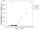
- 1 is a graph showing the relationship between the value of [R GB ]/[M1] and the weight reduction rate in the examples and comparative examples.
- the rare earth sintered magnet of the present invention contains R (R is one or more elements selected from rare earth elements, Nd is essential), Fe, B, M1 (M1 is two or more elements selected from Co, Cu, and Ga, Co is essential), M2 (M2 is one or more elements selected from Al, Si, Cr, Mn, Zn, Ge, Mo, Sn, W, Pb, and Bi), and O.
- R is one or more elements selected from rare earth elements, and Nd is essential.
- the content of R is preferably 12.5 atomic % or more, more preferably 13.0 atomic % or more, from the viewpoint of suppressing the crystallization of ⁇ -Fe in the raw alloy during production and sufficiently densifying it.
- H cJ coercive force
- the amount of liquid phase which is mainly composed of the R component and plays a role in promoting densification in the sintering process described later, decreases, so that the sinterability decreases, and it is possible to prevent insufficient densification of the R-T-B based sintered magnet.
- the content of R is preferably 17 atomic % or less, more preferably 15.5 atomic % or less, and even more preferably 15 atomic % or less.
- the proportion of Nd in R is not particularly limited, but is preferably 60 atomic % or more of all R elements, and more preferably 75 atomic % or more.
- R elements other than Nd are not particularly limited, but may preferably contain Pr, Dy, Tb, Ho, Er, Sm, Ce, Y, etc.
- the Fe content is the remainder other than the R, B, M1, M2, and O, and is preferably 70 atomic % or more, and more preferably 75 atomic % or more , from the viewpoint of obtaining a higher B r .
- the Fe content is not particularly limited, but is preferably 82 atomic % or less, and more preferably 80 atomic % or less, from the viewpoint of suppressing deterioration of squareness and decrease in H cJ due to precipitation of the R 2 T 17 phase.
- the content of B is preferably 5.0 atomic % or more, more preferably 5.5 atomic % or more, and even more preferably 5.7 atomic % or more. In such a range, the ratio of the R 2 T 14 B phase formed is low, and a significant decrease in B r and a deterioration in squareness due to the formation of the R 2 T 17 phase can be suppressed.
- the upper limit is preferably 7.0 atomic % or less, more preferably 6.5 atomic % or less, and even more preferably 6.3 atomic % or less. In such a range, it is easy to avoid the formation of the R 1.1 T 4 B 4 compound phase and the decrease in B r and H cJ .
- the above B may be partially substituted with C.
- the above M1 is two or more elements selected from Co, Cu, and Ga, and Co is essential.
- M1 is preferably 1.0 atomic % or more, and more preferably 1.5 atomic % or more. In this way, the formation of a compound between R and M1 is sufficiently carried out, the formation of a metal R phase with a high R concentration can be suppressed, and the corrosion resistance is improved.
- the upper limit is preferably 3.5 atomic % or less, and more preferably 3.0 atomic % or less. In this way, the decrease in B r and H cJ can be suppressed.
- the Co can replace part of the Fe contained in the R2T14B phase and the grain boundary phase.
- the Co content is preferably 0.5 atomic % or more of the entire magnet, and more preferably 1.0 atomic % or more.
- the Co content is preferably 3.0 atomic % or less, and more preferably 2.0 atomic % or less.
- the Cu content is preferably 0.1 atomic % or more, and more preferably 0.2 atomic % or more, of the entire magnet. From the viewpoint of stably obtaining a high B r , the Cu content is preferably 1.0 atomic % or less, and more preferably 0.5 atomic % or less.
- the Ga content is preferably 0.1 atomic % or more, and more preferably 0.2 atomic % or more, of the entire magnet. From the viewpoint of stably obtaining a high B r , the Ga content is preferably 1.0 atomic % or less, and more preferably 0.5 atomic % or less.
- M2 is one or more elements selected from Al, Si, Cr, Mn, Zn, Ge, Mo, Sn, W, Pb, and Bi.
- the content of M2 is preferably 0.1 atomic % or more, more preferably 0.2 atomic % or more, from the viewpoint of obtaining an optimal temperature range in the heat treatment for ensuring good productivity and further from the viewpoint of suppressing a decrease in HcJ .
- the content is preferably 1.5 atomic % or less, more preferably 1.0 atomic % or less.
- the O content is 0.6 atomic % or less, preferably 0.4 atomic % or less, and more preferably 0.3 atomic % or less. If the O content exceeds 0.6 atomic %, the amount of R-OCN phase or R2O3 phase formed increases, and the effective amount of R functioning as a liquid phase decreases, thereby decreasing HcJ .
- the rare earth sintered magnet of the present invention can contain optional elements other than the above-mentioned R, Fe, B, M1, M2, and O, and can contain the following M3, C, N, etc. as the above-mentioned optional elements.
- M3 is one or more elements selected from Ti, V, Zr, Nb, Hf, and Ta.
- M3 element forms M3B2 compound with B, and exhibits the effect of suppressing abnormal grain growth during sintering.
- the content of M3 is not particularly limited, but is preferably 0.1 atomic % or more, more preferably 0.2 atomic % or more, and even more preferably 0.3 atomic % or more.
- its content is preferably 2.0 atomic % or less, more preferably 1.5 atomic % or less, and even more preferably 1.0 atomic % or less.
- the atomic percentages of B and M3 are [B] and [M3]
- the C is derived from the raw material and the lubricant added to improve the orientation of the fine powder during compaction in a magnetic field, but the C derived from the lubricant is decomposed and removed in the sintering process described below, making it possible to reduce the C content compared to conventional methods.
- the C content is not particularly limited, but is preferably 0.4 atomic % or less, more preferably 0.3 atomic % or less, and even more preferably 0.2 atomic % or less.
- the N content is not particularly limited, but from the viewpoint of obtaining a good HcJ , it is preferably 0.4 atomic % or less, more preferably 0.3 atomic % or less, and even more preferably 0.2 atomic % or less.
- the structure of the rare earth sintered magnet of the present invention includes an R 2 T 14 B intermetallic compound as a main phase.
- the structure includes a plurality of main phase particles and a grain boundary phase that is located between at least two of the main phase particles and contains the R.
- the grain boundary phase may include an M3B 2 phase or the like.
- the rare earth sintered magnet of the present invention may include an R-rich phase in the grain boundary phase, and may include a phase of a compound of an inevitable impurity that is mixed in during the manufacturing process, such as R carbide, R oxide, R nitride, R halide, or R acid halide, but it is preferable to keep it to a minimum in order to suppress a decrease in B r or H cJ .
- the R metal phase with an R content in the range of 50% to 70% is highly active due to the high R concentration, and becomes the starting point of collapse by reacting with a solvent in a corrosion resistance test described later, so the proportion of the R metal phase in the entire grain boundary phase is preferably 3% by volume or less, and more preferably 1% by volume or less.
- the rare earth sintered magnet of the present invention has, in at least a portion of the range of 0.1 to 200 ⁇ m deep from its surface, a composition region (hereinafter referred to as the high corrosion resistance region) that satisfies the following relational expression (3), where the atomic percentage of M1 is [M1] and the atomic percentage of R contributing to the formation of the grain boundary phase is [R GB ]: 1.0 ⁇ [ RGB ]/[M1] ⁇ 2.4...(3)
- the composition in a region shallower than 0.1 ⁇ m from the magnet surface does not contribute to improving corrosion resistance.
- the region having this specific composition is set to a range of 0.1 to 200 ⁇ m from the magnet surface. If the grain boundary phase is insufficient in the above region near the magnet surface, [R GB ] decreases and [R GB ]/[M1] also decreases, and good H cJ cannot be obtained. Furthermore, if an excess of M1 element is present in the above region near the magnet surface, [R GB ]/[M1] decreases and B r and H cJ decrease.
- [R GB ]/[M1] is greater than 1.0 and greater than 1.2.
- [R GB ] and [R GB ]/[M1] increase, and an R metal phase with a high R concentration precipitates in that region, thereby reducing corrosion resistance.
- the M1 concentration in the above region near the magnet surface decreases, [R GB ]/[M1] increases, and the amount of M1 that forms a compound with R is insufficient, causing the R metal phase with a high R concentration to precipitate and reducing corrosion resistance.
- [R GB ]/[M1] is smaller than 2.4, and more preferably smaller than 2.2.
- the following relational expression (4) is further satisfied in the highly corrosion-resistant region.
- the value of [Cu]+[Ga] is 0.28 or more, and more preferably 0.35 or more, from the viewpoint of obtaining an optimum temperature range in the heat treatment for ensuring good productivity and from the viewpoint of obtaining an effect of improving corrosion resistance.
- the upper limit is not particularly limited, but is preferably 1.50 or less, and more preferably 1.00 or less, from the viewpoint of stably obtaining a high Br .
- some of the R, Fe, Co, Cu, and Ga in the highly corrosion-resistant region near the magnet surface may be introduced by grain boundary diffusion.
- the average composition of R, Fe, Co, Cu, and Ga in the highly corrosion-resistant region from the surface to a depth of 0.1 to 200 ⁇ m can be confirmed by using compositional analysis methods such as energy dispersive X-ray spectroscopy (EDS), wavelength dispersive X-ray analysis (WDS), and glow discharge mass spectrometry (GDMS) normalized by ICP analysis values.
- EDS energy dispersive X-ray spectroscopy
- WDS wavelength dispersive X-ray analysis
- GDMS glow discharge mass spectrometry
- the rare earth sintered magnet does not have a change in concentration distribution of each element from the magnet surface to the inside due to the application of a grain boundary diffusion method, etc.
- the average composition of R, Fe, Co, Cu, and Ga in the highly corrosion-resistant region from the surface to a depth of 0.1 to 200 ⁇ m of the rare earth sintered magnet can be substituted with the content of metal elements contained in the entire magnet determined by ICP analysis.
- the rare earth sintered magnet of the present invention has a region (high corrosion resistance region) whose average composition satisfies the above relational expression (3) in at least a part of the range of 0.1 to 200 ⁇ m deep from the surface.
- the rare earth sintered magnet of the present invention has the above high corrosion resistance region near the magnet surface, which improves its corrosion resistance, and since the larger the high corrosion resistance region is relative to the magnet surface area, the higher the corrosion resistance can be obtained, it is preferable to satisfy the following relational expression, where S is the surface area of the magnet and S R is the area obtained by projecting the high corrosion resistance region onto the adjacent magnet surface. 0.53 ⁇ S R /S ⁇ 1...(5) It is more preferable that S R /S is 0.6 or more.
- S R /S is a maximum of 1 when various elements are supplied from the entire surface of the magnet, and in the case where grain boundary diffusion is not performed, it is a maximum of 1 when the content of metal elements contained in the entire magnet satisfies the relational expression (3).
- S R for example, for magnets in which grain boundary diffusion is performed under the same conditions only from two opposing surfaces, the average composition of any region within a depth range of 0.1 to 200 ⁇ m from the surface of the diffusion surface can be treated as a representative value including the opposing diffusion surface.
- the ICP analysis composition of the base material to which the grain boundary diffusion treatment is performed can be used as a representative value.
- the method for obtaining S R is not particularly limited, but from the viewpoint of simplicity, it is preferable to use WDS (Wave-length Dispersive X-ray Spectroscopy).
- WDS Wide-length Dispersive X-ray Spectroscopy
- the beam diameter during WDS measurement is preferably sufficiently larger than the average crystal grain size of the magnet to be measured in order to obtain the average composition of the structure including multiple main phases, grain boundary phases, and grain boundary triple junctions, for example, 30 ⁇ m or more, more preferably 50 ⁇ m or more.
- the magnet is divided into 2 mm x 2 mm x 2 mm to 1 mm x 1 mm x 1 mm by cutting or the like, and the magnet after division is analyzed to obtain S R , and the area lost by cutting or the like can be deducted in advance from the magnet surface area S.
- the corrosion resistance of the present invention can be evaluated by the following method.
- the magnet is then removed, degreased with ethanol, ultrasonically cleaned in water, dried, and the weight of the magnet is measured to obtain the post-test weight.
- the weight loss rate due to the corrosion resistance test obtained by the above method is preferably 1% or less, and more preferably 0.5% or less, from the viewpoint of maintaining good magnetic properties even after the test.
- the average crystal grain size ( ⁇ m) in the plane parallel to the magnetization direction of the rare earth sintered magnet of the present invention is preferably 4 ⁇ m or less, more preferably 3.5 ⁇ m or less, from the viewpoint of improving corrosion resistance by reducing the effect of weight loss caused by the shedding of the main phase due to the collapse of the grain boundary phase in a corrosion resistance test, and obtaining sufficient H cJ .
- the lower limit of this average crystal grain size ( ⁇ m) is preferably 1.2 ⁇ m or more, more preferably 1.8 ⁇ m or more, from the viewpoint of obtaining a sufficient degree of orientation within an appropriate range of the amount of lubricant added.
- the average crystal grain size in the present invention is defined as the area median diameter obtained from a histogram showing the particle size distribution in which the ratio of the area occupied by crystal grains for every 1 ⁇ m average particle interval is plotted for the circle equivalent diameter of each particle.
- the area median diameter can be calculated by creating a histogram of the crystal grain area ratio from the diameter of each particle calculated as the circle equivalent diameter and fitting it with a Gaussian function.
- the circle equivalent diameter of the above-mentioned particles can be measured, for example, by the following procedure.
- the cross-sectional area of each particle is measured by image analysis, and the diameter as an equivalent circle is calculated.
- the average crystal grain size may be, for example, the average of a total of about 2,000 particles in 20 different images.
- the measurement device is not particularly limited, but for example, a 3D measuring laser microscope (LEXT OLS 4000, manufactured by Olympus Corporation) can be used, and image analysis software (Win ROOF, manufactured by Mitani Shoji Co., Ltd.) can be used for image analysis.
- a 3D measuring laser microscope LEXT OLS 4000, manufactured by Olympus Corporation
- image analysis software Win ROOF, manufactured by Mitani Shoji Co., Ltd.
- the rare earth sintered magnet of the present invention is preferably produced in a process that reduces the amount of impurity elements contained to the utmost limit.
- the formation of compounds between the impurity elements and R is not promoted, and an R metal phase with a high R concentration is more likely to form.
- This R metal phase has a low corrosion potential and is therefore likely to become the starting point for corrosion, resulting in weight loss and reduced magnetic properties.
- Methods for suppressing the formation of the R metal phase include reducing the R content and including an element other than the impurity elements that is likely to form a compound with R.
- the element added in the latter method is the above-mentioned M1, and by adjusting the content of this M1 to an appropriate range as described above, it is possible to achieve high magnetic properties and excellent corrosion resistance.
- the process for manufacturing the rare earth sintered magnet of the present invention includes a melting step in which the raw material is melted to obtain a raw material alloy having a predetermined composition, a crushing step in which the raw material alloy is crushed to prepare an alloy fine powder, a molding step in which the alloy fine powder is compressed under an applied magnetic field to obtain a green body, and a sintering step in which the green body is heat-treated to obtain a sintered body.
- the metal or alloy that is the raw material of each element is weighed to obtain a predetermined composition.
- the raw material is melted by, for example, high-frequency melting, and cooled to produce a raw alloy.
- the casting of the raw alloy is generally performed by melting and casting into a flat mold or a book mold, or by strip casting.
- the present invention can also be applied to a so-called two-alloy method in which an alloy close to the main phase R 2 Fe 14 B compound composition and an R-rich alloy that becomes a liquid phase auxiliary at the sintering temperature are separately prepared, and then weighed and mixed after coarse grinding.
- an alloy close to the main phase composition is likely to crystallize out of the ⁇ -Fe phase depending on the cooling rate and alloy composition during casting, it is preferable to perform a homogenization treatment for 1 hour or more in a vacuum or Ar atmosphere as necessary in order to homogenize the structure and eliminate the ⁇ -Fe phase.
- a homogenization treatment for 1 hour or more in a vacuum or Ar atmosphere, homogenization can be omitted.
- an R-rich alloy that serves as a liquid phase assistant in addition to the above-mentioned casting method, the so-called liquid quenching method can also be applied.
- the above-mentioned crushing process is a multi-stage process including at least a coarse crushing process and a fine crushing process.
- a coarse crushing process for example, a jaw crusher, a Braun mill, a pin mill, or hydrogen crushing can be used as appropriate.
- a hydrogen crushing process is a crushing process by hydrogen absorption in which the alloy is absorbed by exposing the alloy block to a hydrogen atmosphere of a certain pressure or more.
- the hydrogen pressure at this time is not particularly limited, but from the viewpoint of reducing the adverse effect on productivity due to the time required for hydrogen absorption, it is preferable that it is 100 kPa or more.
- dehydrogenation treatment may be performed as necessary.
- the alloy block with an increased temperature is cooled and transported to the next process. At this time, it is preferable to cool it to around room temperature from the viewpoint of preventing oxidation.
- the coarse powder obtained in the coarse pulverization step can be pulverized using a jet mill using a non-oxidizing gas stream such as N 2 , He, or Ar.
- the coarse powder in this fine pulverization step, is pulverized to a volume-based median diameter D50 of preferably 0.2 ⁇ m to 10 ⁇ m, more preferably 1.2 ⁇ m to 4.0 ⁇ m, and even more preferably 1.5 to 3.5 ⁇ m. Since O and N in the rare earth sintered magnet are mainly mixed in during the fine pulverization step, it is necessary to control the jet mill atmosphere in order to adjust the O and N contents in the rare earth sintered magnet.
- the O content in the rare earth sintered magnet is adjusted by controlling the O amount and dew point in the jet mill atmosphere, and the moisture content in the atmosphere during pulverization is preferably 100 ppm or less, and the oxygen concentration is preferably 1 ppm or less.
- the volume-based median diameter D50 is the particle diameter when the cumulative volume frequency is 50%.
- the N content in the rare earth sintered magnet can be adjusted, for example, by (A) a method of pulverizing the magnet in a jet mill using a He or Ar gas stream, (B) a method of pulverizing the magnet by introducing hydrogen into a jet mill using a N2 gas stream, or (C) a method of pulverizing the magnet in a jet mill using a hydrogen-containing coarse powder using a N2 gas stream.
- hydrogen is preferentially adsorbed onto the active surface generated by pulverization by introducing hydrogen gas or using a coarse powder using hydrogen, and the adsorption of nitrogen is inhibited, thereby making it possible to reduce the amount of N in the rare earth sintered magnet.
- the hydrogen-containing coarse powder in method (C) above can be prepared, for example, by omitting the dehydrogenation process in the hydrogen crushing step, by absorbing hydrogen into the coarse powder after the dehydrogenation process, or by absorbing hydrogen into the coarse powder obtained by mechanical crushing in a He or Ar gas atmosphere.
- the hydrogen content of the coarse powder or the fine powder after crushing is preferably 0.1 to 1.0 mass%, and more preferably 0.2 to 0.5 mass%.
- the hydrogen content of the coarse powder or the fine powder after crushing can be determined by measuring the change in weight before and after hydrogen absorption.
- a lubricant consisting of, for example, a saturated fatty acid or its ester can be appropriately added before or after the above-mentioned coarse crushing step in order to improve the orientation of the powder in the next step of molding in a magnetic field.
- a lubricant is effective in improving the orientation, a dilemma arises in that many R-OCN phases are formed in the rare earth sintered magnet due to the C derived from the lubricant, and H cJ drops significantly. Therefore, in order to suppress the drop in H cJ , it is preferable to add a lubricant when the above-mentioned method (C) is adopted.
- the lubricant chemically adsorbed on the fine powder surface is decomposed by the hydrogen through a carbonyl reduction reaction or the like, and further decomposed and dissociated into a highly volatile lower alcohol through a cracking reaction by hydrogen gas, which is believed to reduce the C content remaining in the rare earth sintered magnet.
- the amount of the lubricant added is appropriately set depending on the type of lubricant, and is not particularly limited, but is preferably 0.01 to 0.50 parts by mass, and more preferably 0.05 to 0.30 parts by mass, per 100 parts by mass of the coarsely pulverized powder or raw alloy.
- a magnetic field of 400 to 1600 kA/m is applied, and the alloy powder is compacted in a compression molding machine while being oriented in the direction of the easy axis of magnetization.
- it is preferable to set the density of the compact to 2.8 to 4.2 g/cm 3. That is, from the viewpoint of ensuring the strength of the compact and obtaining good handling properties, it is preferable to set the density of the compact to 2.8 g/cm 3 or more.
- a binder such as PVA or fatty acid can be added to increase the strength of the compact after molding.
- the density of the compact is 4.2 g/cm 3 or less.
- the sintering step is a step of sintering the molded body obtained in the molding step in an inert gas atmosphere such as Ar gas or in a high vacuum, and preferably includes an atmospheric heat treatment step in which heat treatment is performed in an inert gas atmosphere, and a vacuum heat treatment step in which heat treatment is performed in a vacuum atmosphere.
- the atmospheric heat treatment step is preferably held in an inert gas atmosphere at 300 to 600°C for 1 to 10 hours, although there is no particular limit to this.
- the vacuum heat treatment step it is preferably held in a high vacuum at 950 to 1200°C for 0.5 to 10 hours, although there is no particular limit to this.
- the obtained sintered body may be subjected to a heat treatment or a grain boundary diffusion step at a temperature lower than the sintering temperature in order to increase HcJ .
- the heat treatment at a temperature lower than the sintering temperature may be a two-stage heat treatment of a high-temperature heat treatment and a low-temperature heat treatment, or only a low-temperature heat treatment may be performed.
- the sintered body is preferably heat-treated at a temperature of 600 to 950°C, and in the low-temperature heat treatment, the sintered body is preferably heat-treated at a temperature of 400 to 600°C.
- the grain boundary diffusion step may be carried out for the purpose of increasing the HcJ of the obtained sintered body and forming a highly corrosion-resistant region, and includes a diffusion source providing step of providing a diffusion source on the surface of the obtained sintered body, and a diffusion heat treatment step of heat-treating the sintered body and the diffusion source in a vacuum or inert gas atmosphere.
- the composition of the diffusion source is not particularly limited, but can be appropriately selected according to the above-mentioned purpose, for example.
- R2 is one or more elements selected from Dy and Tb
- HcJ is one or more elements selected from Co, Cu, and Ga
- M1 is one or more elements selected from Co, Cu, and Ga
- the diffusion source powder can be dispersed in an organic solvent such as alcohol or water to form a slurry, and the sintered body can be immersed in this slurry and then lifted out and dried with hot air or vacuum, or allowed to dry naturally.
- the diffusion source powder can be mixed with a resin slurry, stirred, and then formed into a sheet that can be attached to the sintered body.
- R2 is concentrated near the grain boundaries in the main phase of the magnet in order to obtain a sufficient increase in coercivity
- M1 is concentrated in a range of 0.1 to 200 ⁇ m deep from the magnet surface so as to satisfy the above-mentioned relations (3) and (5) in order to enhance corrosion resistance.
- Specific conditions are not particularly limited, but conditions are preferred where the R2 element and/or M1 element is heated to a temperature of more than 400°C, particularly 500°C or higher, and 1100°C or lower, particularly 1050°C or lower, and especially 1000°C or lower, to diffuse into the sintered body.
- the heat treatment time is preferably 1 minute to 50 hours to avoid deterioration of the structure of the sintered body and adverse effects of inevitable oxidation and evaporation of components on the magnetic properties and corrosion resistance.
- the diffusion source is applied to 53% or more of the total surface area of the magnet so that the area of the high corrosion resistance region satisfies relational expression (5).
- Examples 1 to 3 Nd metal, ferroboron alloy, electrolytic Co, Al metal, Cu metal, Ga metal, Zr metal and electrolytic iron (all metals have a purity of 99% or more) were weighed and mixed in a predetermined ratio, melted, and cast by a strip casting method to obtain a flake-shaped raw alloy having a thickness of 0.2 to 0.4 mm. The obtained flake-shaped raw alloy was subjected to hydrogen embrittlement in a hydrogen pressure atmosphere to obtain a coarsely pulverized powder.
- pulverized particle size (D50) is a volume-based median diameter obtained by a laser diffraction method using an airflow dispersion method.
- the finely pulverized powder was filled into a mold of a molding machine in a N2 gas atmosphere, and while oriented in a magnetic field of 15 kOe (1.19 MA/m), it was pressure molded in a direction perpendicular to the magnetic field.
- the density of the molded body at this time was 3.0 to 4.0 g/ cm3 .
- the obtained molded body was subjected to an atmospheric heat treatment in which the temperature was raised to 500°C in an Ar gas atmosphere and heat-treated, and then sintered in a vacuum at 1040 to 1080°C (a temperature at which sufficient densification by sintering occurs for each sample) for 5 hours to obtain a Nd magnet material.
- the density of the resulting Nd magnet was 7.5 g/cm3 or more .
- the central part of the resulting magnet was subjected to metal component analysis using inductively coupled plasma optical emission spectroscopy (ICP-OES), and the oxygen concentration was measured by inert gas fusion infrared absorption spectrometry, the nitrogen concentration by inert gas fusion thermal conductivity spectrometry, and the carbon concentration by combustion infrared absorption spectrometry.
- ICP-OES inductively coupled plasma optical emission spectroscopy
- the structure of the obtained magnet was observed using an EPMA (Electron Probe Micro Analyzer), the R metal phase was identified from the backscattered electron image and the results of semi-quantitative analysis, and the proportion of the R metal phase contained in the entire grain boundary phase of the magnet was measured using image processing. The results are shown in Table 2.
- the magnets thus obtained were cut into rectangular parallelepiped shapes measuring L 15 mm x W 7 mm x T (magnetization direction) 12 mm, and B r and H cJ were measured using a BH tracer. The results are shown in Table 2.
- Table 2 also shows the calculated values of the relational expressions (3) and (4) defined in the present invention. Note that in Examples 1 to 3 and Comparative Examples 1 to 3, grain boundary diffusion treatment was not performed, and it is presumed that there is no change in concentration distribution from the magnet surface to the inside. Therefore, the average composition of R, Fe, Co, Cu, and Ga in the range of 0.1 to 200 ⁇ m was substituted with the content of metal elements contained in the entire magnet determined by the ICP-OES analysis, and this region was defined as the entire magnet surface.
- the average crystal grain size [ ⁇ m] of the obtained magnets was measured using a laser microscope, and was found to be 3.5 ⁇ m for all of Examples 1 to 3 and Comparative Examples 1 to 3.
- Example 4 to 6 Comparative Examples 4 to 6
- Magnets were produced in the same manner as in Example 1.
- metal component analysis was performed using ICP-OES, and the oxygen concentration was measured by inert gas fusion infrared absorption, the nitrogen concentration by inert gas fusion thermal conduction, and the carbon concentration by combustion infrared absorption.
- the results are shown in Table 3.
- the proportion of R metal phase and the weight loss rate in the corrosion resistance evaluation test were calculated in the same manner as in Example 1.
- Table 4 also shows the calculated values of the relational expressions (3) and (4) defined in the present invention.
- the average crystal grain size [ ⁇ m] of the resulting magnets was measured using a laser microscope, and was 3.5 ⁇ m for all of Examples 4 to 6 and Comparative Examples 4 to 6.
- Example 7 to 12 Comparative Example 7
- Magnets were produced in the same manner as in Example 1.
- metal component analysis was performed using ICP-OES, and the oxygen concentration was measured by inert gas fusion infrared absorption, the nitrogen concentration by inert gas fusion thermal conduction, and the carbon concentration by combustion infrared absorption.
- the results are shown in Table 5.
- the proportion of R metal phase and the weight loss rate in the corrosion resistance evaluation test were calculated in the same manner as in Example 1.
- Table 6 also shows the calculated values of the relational expressions (3) and (4) defined in the present invention.
- the average crystal grain size [ ⁇ m] of the resulting magnets was measured using a laser microscope, and was 3.5 ⁇ m for all of Examples 7 to 12 and Comparative Example 7.
- Comparative Example 7 When comparing Examples 7 to 12 with Comparative Example 7, all magnets satisfy the relationship of formula (3). However, Comparative Example 7, which does not satisfy the relationship of formula (4), has a high proportion of the R metal phase and a high weight loss rate. This is thought to be the result of the formation of compounds between R, Cu, and Ga not being promoted, leading to the formation of the R metal phase not being suppressed.
- Tb metal, electrolytic iron, electrolytic cobalt, and Ga metal were weighed and mixed in an atomic ratio of 1:1:1, and the raw materials were melted in an arc melting furnace to obtain TbFeGa and TbFeCo alloy ingots. These alloy ingots were then heat-treated in a vacuum atmosphere at 1050° C. for 10 hours. The heat-treated alloy ingots were pulverized in a ball mill to prepare alloy powder with a D50 of about 10 ⁇ m. The alloy powder was mixed with a water-soluble PVA resin slurry in a ratio of 7:3, stirred, molded to a thickness of 50 ⁇ m, and dried to produce TbFeGa alloy sheets and TbFeCo alloy sheets.
- Example 13 a TbFeGa alloy sheet
- Example 14 a TbFeCo alloy sheet
- the average crystal grain size [ ⁇ m] of the resulting magnets was measured using a laser microscope and was 3.5 ⁇ m for both Example 13 and Example 14.
- Comparative Example 1 A comparison of Comparative Example 1 with Examples 13 and 14 reveals that the base material (Comparative Example 1) did not satisfy the corrosion resistance, but that the corrosion resistance was improved by carrying out the grain boundary diffusion treatment. This is thought to be because the Ga and Co contained in the diffusion source are introduced into the base material, changing the calculated value of [R GB ]/[M1] before and after the grain boundary diffusion, improving the corrosion resistance. Furthermore, in Examples 13 and 14, the value of S R /S satisfies the relationship of formula (5), and since there is a sufficient high corrosion resistance region relative to the magnet surface area, it is thought that there is sufficient corrosion resistance.
- the magnets of Examples 1 to 14 which satisfy the requirements of the present invention, showed almost no weight loss in the corrosion resistance evaluation test, and possess high magnetic properties and sufficient corrosion resistance.
Landscapes
- Chemical & Material Sciences (AREA)
- Engineering & Computer Science (AREA)
- Mechanical Engineering (AREA)
- Materials Engineering (AREA)
- Metallurgy (AREA)
- Organic Chemistry (AREA)
- Crystallography & Structural Chemistry (AREA)
- Inorganic Chemistry (AREA)
- Power Engineering (AREA)
- Manufacturing & Machinery (AREA)
- Hard Magnetic Materials (AREA)
Abstract
Description
本発明は、高い磁気特性を有し、かつ耐食性に優れる希土類焼結磁石に関する。 The present invention relates to rare earth sintered magnets that have high magnetic properties and excellent corrosion resistance.
希土類焼結磁石は、省エネや高機能化に必要不可欠な機能性材料であり、その応用範囲と生産量は年々拡大している。希土類焼結磁石の中でも特にNd系焼結磁石は高い残留磁束密度(以下、Brともいう。)を有し、例えば、ハイブリッド自動車や電気自動車の駆動用モータ、電動パワーステアリング用モータ、エアコンのコンプレッサー用モータ、ハードディスクドライブのボイスコイルモータ(VCM)等、種々の用途、環境においてに用いられている。 Rare earth sintered magnets are essential functional materials for energy conservation and high performance, and their range of applications and production volume are expanding year by year. Among rare earth sintered magnets, Nd-based sintered magnets in particular have high residual magnetic flux density (hereinafter also referred to as B r ), and are used in a variety of applications and environments, such as drive motors for hybrid and electric vehicles, motors for electric power steering, motors for air conditioner compressors, and voice coil motors (VCMs) for hard disk drives.
一方で希土類焼結磁石は希土類元素Rを含有していることから腐食しやすいといった問題があり、腐食は一部のR-リッチ相を起点として発生し、主相の脱離を伴ってさらに進行していくことが知られている。これに対し、近年では希土類磁石には高い磁気特性が要求されることから、磁石に含まれる不純物元素を極限まで低減する必要があり、これに伴い希土類焼結磁石に含まれる有効R量が増加し耐食性が低下する傾向にある。特に、自動車のウォーターポンプとして用いられる場合、モータに組み込まれた磁石が不凍液に直接触れる過酷な環境で使用されることから、磁気特性と高い耐食性を両立する必要があり、種々の手法が提案されている。 On the other hand, rare earth sintered magnets have the problem that they are susceptible to corrosion due to the rare earth element R they contain, and it is known that corrosion begins in some R-rich phases and progresses further as the main phase is removed. In response to this, in recent years, high magnetic properties are required of rare earth magnets, and it has become necessary to reduce the impurity elements contained in the magnets to the utmost, which has resulted in an increase in the effective R content of rare earth sintered magnets and a tendency for corrosion resistance to decrease. In particular, when used as water pumps for automobiles, the magnets built into the motor are used in harsh environments where they come into direct contact with antifreeze, so it is necessary to achieve both magnetic properties and high corrosion resistance, and various methods have been proposed.
例えば、特開2007-300791号公報(特許文献1)には、磁石表面に電気Niメッキ被膜を形成することで水中での使用も可能となるような高い耐食性を付与する方法が提案されている。 For example, Japanese Patent Application Laid-Open No. 2007-300791 (Patent Document 1) proposes a method of forming an electric Ni plating film on the magnet surface to impart high corrosion resistance that allows it to be used underwater.
また、特開2020-102551号公報(特許文献2)には、磁石表面から内部に向かって減少する濃度勾配を有するように粒界にCuを存在させ、かつ表面から0.1~5μmの深さの領域において粒界に酸化層を設けることでウォーターポンプ中での耐食性が向上することが記載されている。 In addition, JP 2020-102551 A (Patent Document 2) describes that by making Cu present at the grain boundaries so that there is a concentration gradient that decreases from the magnet surface toward the inside, and by providing an oxide layer at the grain boundaries in a region 0.1 to 5 μm deep from the surface, corrosion resistance in a water pump is improved.
さらに、特開2021-61301号公報(特許文献3)には、磁石の粒界相全体として希土類元素の含有量が55質量%以上であり、Cuを8質量%以上含有するCuリッチ領域が粒界相のうちの9体積%以上を占めるような組織を形成させることにより、高い耐食性が得られることが記載されている。 Furthermore, JP 2021-61301 A (Patent Document 3) describes that high corrosion resistance can be obtained by forming a structure in which the grain boundary phase of the magnet as a whole contains 55 mass% or more of rare earth elements, and Cu-rich regions containing 8 mass% or more of Cu account for 9 volume% or more of the grain boundary phase.
しかしながら、特許文献1に記載されるようなNiメッキ層を形成させる方法をとった場合、メッキ工程を行うことによりコストが上昇するとともに、メッキに不具合があった場合に磁石が使用環境に直接晒されることで崩壊してしまうことが懸念される。 However, if the method of forming a Ni plating layer as described in Patent Document 1 is used, the plating process increases costs, and there is a concern that if there is a defect in the plating, the magnet may disintegrate due to direct exposure to the usage environment.
また、特許文献2に記載の方法においては、所定の組織を形成するためにCuを含有するR合金を粒界拡散させるとともに、表面酸化層を形成する必要があることから工程が多くなり、コスト上昇を招くことになる。
In addition, the method described in
さらに、特許文献3に記載の方法においては、重希土類元素を含む希土類元素と、Cuと、FeまたはFeの一部をCoで置換したTとを含有する粒界相を形成する必要があるが、特に重希土類元素は資源リスクが高く、価格も高いことから含有しないことが好ましい。 Furthermore, in the method described in Patent Document 3, it is necessary to form a grain boundary phase containing rare earth elements including heavy rare earth elements, Cu, and Fe or T in which part of Fe has been replaced with Co. However, it is preferable not to contain heavy rare earth elements in particular, since they have a high resource risk and are expensive.
本発明は、上記課題を鑑みてなされたものであり、磁石表面に特定の組成領域を形成することにより高い磁気特性を有し、かつ耐食性に優れる希土類焼結磁石を提供することを目的とする。 The present invention was made in consideration of the above problems, and aims to provide a rare earth sintered magnet that has high magnetic properties and excellent corrosion resistance by forming a specific composition region on the magnet surface.
本発明者らは上記目的を達成するために、希土類焼結磁石の組成、特に磁石表面近傍の特定の領域における粒界相の形成に寄与するR元素とM元素(Co、Cu、Ga)との含有量の関係に着目して鋭意研究を重ねた結果、R含有量を少なくする、あるいは一定量以上のM元素を添加することにより、粒界相中のRとMとで金属間化合物が形成されR金属相が消失することで、耐食性が向上することを見出し、本発明を完成したものである。 In order to achieve the above objective, the inventors conducted extensive research focusing on the composition of rare earth sintered magnets, in particular the relationship between the content of R elements and M elements (Co, Cu, Ga) that contribute to the formation of grain boundary phases in specific regions near the magnet surface. As a result, they discovered that by reducing the R content or adding a certain amount of M element or more, an intermetallic compound is formed between R and M in the grain boundary phase, causing the R metal phase to disappear, thereby improving corrosion resistance, and thus completing the present invention.
従って、本発明は以下の希土類焼結磁石を提供する。
1. R(Rは希土類元素から選ばれる1種類以上の元素であり、Ndを必須とする。)、Fe、B、M1(M1はCo、Cu、Gaから選ばれる2種類以上の元素であり、Coを必須とする。)、M2(M2はAl、Si,Cr,Mn,Zn、Ge、Mo、Sn、W、Pb、Biから選ばれる1種類以上の元素である。)及びOを含む希土類焼結磁石であって、
前記Oの含有量が0.6原子%以下であり、
R2Fe14B金属間化合物である複数の主相粒子と、少なくとも二つの前記主相粒子の間に位置し、かつ前記Rを含有する粒界相とを有し、
磁石表面から深さ0.1~200μmの範囲の内の少なくとも一部に、R、Fe、Co、Cu、Ga、M1の原子百分率をそれぞれ[R]、[Fe]、[Co]、[Cu]、[Ga]、[M1]とし、前記粒界相の形成に寄与するRの原子百分率を[RGB]とした場合に、下記の関係式(1)~(4)を満足する領域を有することを特徴とする希土類焼結磁石。
[RGB]=[R]-[Fe]/7 ・・・(1)
[M1]=[Co]+[Cu]+[Ga]・・・(2)
1.0<[RGB]/[M1]<2.4 ・・・(3)
[Cu]+[Ga]≧0.28 ・・・(4)
2. 磁石の表面積をSとし、磁石の表面からの深さ0.1~200μmの範囲で前記(1)~(4)の関係式を満たす領域を近接する磁石表面に投影して得られる面積をSRとした場合に、下記の関係式(5)を満足することを特徴とする1の希土類焼結磁石。
0.53≦SR/S≦1 ・・・(5)
3. 前記粒界相中における、Rの含有率が50~70原子%であるR金属相の含有率が、3体積%以下であることを特徴とする1又は2の希土類焼結磁石。
4. 0.1~2.0原子%のM3(M3はTi、V、Zr、Nb、Hf、Taから選ばれる1種類以上の元素である。)を含有することを特徴とする1~3のいずれかの希土類焼結磁石。
5. Bの原子百分率を[B]、M3の原子百分率を[M3]とした場合に、下記の関係式(6)を満足することを特徴とする4の希土類焼結磁石。
[B]-2×[M3]≧[Fe]/14・・・(6)
6. Cの含有量が0.4原子%以下であることを特徴とする1~5のいずれかの希土類焼結磁石。
7. Nの含有量が0.4原子%以下であることを特徴とする1~6のいずれかの希土類焼結磁石。
8. 磁化方向に対して平行な面における円相当径で求めた前記主相粒子の平均結晶粒径が4μm以下である1~7のいずれかの希土類焼結磁石。
9. 下記方法で測定した重量減少率が1%以下である1~8のいずれかの希土類焼結磁石。
[測定方法]
5mm×5mm×2mmの直方体形状に切り出した試料を、エチレングリコール:水=1:1(容量比)のエチレングリコール水混合液に浸漬させ密閉した状態に120℃で480時間保持し、試料の重量の減少率を測定する。
Accordingly, the present invention provides the following rare earth sintered magnet.
1. A rare earth sintered magnet containing R (R is one or more elements selected from rare earth elements, and Nd is essential), Fe, B, M1 (M1 is two or more elements selected from Co, Cu, and Ga, and Co is essential), M2 (M2 is one or more elements selected from Al, Si, Cr, Mn, Zn, Ge, Mo, Sn, W, Pb, and Bi), and O,
The content of O is 0.6 atomic % or less,
The alloy has a plurality of main phase grains which are an R2Fe14B intermetallic compound, and a grain boundary phase which is located between at least two of the main phase grains and contains the R,
A rare earth sintered magnet characterized in that at least a portion of a range of 0.1 to 200 μm deep from the magnet surface has a region that satisfies the following relationship expressions (1) to (4), when the atomic percentages of R, Fe, Co, Cu, Ga, and M1 are [R], [Fe], [Co], [Cu], [Ga], and [M1], respectively, and the atomic percentage of R contributing to the formation of the grain boundary phase is [R GB ].
[ RGB ]=[R]-[Fe]/7...(1)
[M1]=[Co]+[Cu]+[Ga]...(2)
1.0<[ RGB ]/[M1]<2.4...(3)
[Cu]+[Ga]≧0.28...(4)
2. The rare earth sintered magnet of item 1, characterized in that the following relational expression (5) is satisfied, where S is the surface area of the magnet, and S R is the area obtained by projecting onto the adjacent magnet surface an area that satisfies the relational expressions (1) to (4) within a depth range of 0.1 to 200 μm from the magnet surface:
0.53≦S R /S≦1 (5)
3. The rare earth sintered magnet of 1 or 2, characterized in that the content of R metal phase in the grain boundary phase, in which the content of R is 50 to 70 atomic %, is 3 volume % or less.
4. The rare earth sintered magnet according to any one of 1 to 3, characterized in that it contains 0.1 to 2.0 atomic % of M3 (M3 is one or more elements selected from Ti, V, Zr, Nb, Hf, and Ta).
5. The rare earth sintered magnet of 4, wherein the atomic percentage of B is [B] and the atomic percentage of M3 is [M3], the following relational expression (6) is satisfied:
[B]-2×[M3]≧[Fe]/14...(6)
6. The rare earth sintered magnet according to any one of 1 to 5, characterized in that the C content is 0.4 atomic % or less.
7. The rare earth sintered magnet according to any one of 1 to 6, characterized in that the N content is 0.4 atomic % or less.
8. The rare earth sintered magnet of any one of 1 to 7, wherein the main phase grains have an average crystal grain size of 4 μm or less, determined as a circle equivalent diameter in a plane parallel to the magnetization direction.
9. A rare earth sintered magnet according to any one of 1 to 8, having a weight loss rate of 1% or less as measured by the following method:
[Measurement method]
A sample cut into a rectangular parallelepiped shape of 5 mm x 5 mm x 2 mm is immersed in an ethylene glycol-water mixture of ethylene glycol:water = 1:1 (volume ratio) and kept in a sealed state at 120°C for 480 hours, and the weight loss rate of the sample is measured.
本発明によれば、後処理工程による保護膜の形成なく高い耐食性を付与することができるとともに、必ずしも重希土類元素を用いた粒界拡散工程を必要としないことからコスト面にも優れた希土類焼結磁石を得ることができる。 The present invention can provide high corrosion resistance without forming a protective film through a post-treatment process, and does not necessarily require a grain boundary diffusion process using heavy rare earth elements, making it possible to obtain a rare earth sintered magnet that is also cost-effective.
本発明の希土類焼結磁石は、R(Rは希土類元素から選ばれる1種類以上の元素であり、Ndを必須とする。)、Fe、B、M1(M1はCo、Cu、Gaから選ばれる2種類以上の元素であり、Coを必須とする。)、M2(M2はAl、Si,Cr,Mn,Zn、Ge、Mo、Sn、W、Pb、Biから選ばれる1種類以上の元素である。)及びOを含むものである The rare earth sintered magnet of the present invention contains R (R is one or more elements selected from rare earth elements, Nd is essential), Fe, B, M1 (M1 is two or more elements selected from Co, Cu, and Ga, Co is essential), M2 (M2 is one or more elements selected from Al, Si, Cr, Mn, Zn, Ge, Mo, Sn, W, Pb, and Bi), and O.
Rは、上述したように、希土類元素から選ばれる1種以上の元素であり、Ndを必須とする。Rの含有率は、製造時の原料合金においてα-Feの晶出が起こることの抑制及び緻密化を十分に行う観点から、12.5原子%以上が好ましく、13.0原子%以上であることがより好ましい。なお、均質化を施してもα-Feを消失させることは難しいが、上記の範囲であれば、R-T-B系焼結磁石の保磁力(以下、HcJともいう。)や角形性が大きく低下することを抑制することが出来る。これは、α-Feの晶出が起こり難いストリップキャスト法により原料合金を作製する場合でも同様である。加えて、後述する焼結過程において緻密化を促進させる役割をもつ主にR成分からなる液相量が少なくなるために焼結性が低下し、R-T-B系焼結磁石の緻密化が不足することを防ぐことが出来る。一方、Rの含有率が高すぎると焼結磁石中のR2T14B相の割合が低くなりBrが低下する。よって、このBr低下を防止する観点からRの含有率は17原子%以下であることが好ましく、15.5原子%以下であることがより好ましく、15原子%以下であることがさらに好ましい。 As described above, R is one or more elements selected from rare earth elements, and Nd is essential. The content of R is preferably 12.5 atomic % or more, more preferably 13.0 atomic % or more, from the viewpoint of suppressing the crystallization of α-Fe in the raw alloy during production and sufficiently densifying it. Although it is difficult to eliminate α-Fe even by homogenization, if it is within the above range, it is possible to suppress a significant decrease in the coercive force (hereinafter also referred to as H cJ ) and squareness of the R-T-B based sintered magnet. This is also true when the raw alloy is produced by the strip casting method, in which crystallization of α-Fe is unlikely to occur. In addition, the amount of liquid phase, which is mainly composed of the R component and plays a role in promoting densification in the sintering process described later, decreases, so that the sinterability decreases, and it is possible to prevent insufficient densification of the R-T-B based sintered magnet. On the other hand, if the content of R is too high, the proportion of the R 2 T 14 B phase in the sintered magnet decreases, and B r decreases. Therefore, from the viewpoint of preventing this decrease in B r, the content of R is preferably 17 atomic % or less, more preferably 15.5 atomic % or less, and even more preferably 15 atomic % or less.
R中のNdの割合は、特に制限されるもではないが、全R元素の60原子%以上であることが好ましく、より好ましくは75原子%以上である。また、Nd以外のR元素としては、特に制限されるものではないが、Pr、Dy、Tb、Ho、Er、Sm、Ce、Yなどを好ましく含有することができる。 The proportion of Nd in R is not particularly limited, but is preferably 60 atomic % or more of all R elements, and more preferably 75 atomic % or more. In addition, R elements other than Nd are not particularly limited, but may preferably contain Pr, Dy, Tb, Ho, Er, Sm, Ce, Y, etc.
上記Feの含有率は上記R、B、M1、M2、O以外の残部とされるが、より高いBrを得る観点から70原子%以上であることが好ましく、75原子%以上であることがより好ましい。また、Feの含有率は特に制限されるものではないが、R2T17相の析出による角形性の悪化やHcJの低下を抑制する観点から、82原子%以下であることが好ましく、80原子%以下であることがより好ましい。 The Fe content is the remainder other than the R, B, M1, M2, and O, and is preferably 70 atomic % or more, and more preferably 75 atomic % or more , from the viewpoint of obtaining a higher B r . The Fe content is not particularly limited, but is preferably 82 atomic % or less, and more preferably 80 atomic % or less, from the viewpoint of suppressing deterioration of squareness and decrease in H cJ due to precipitation of the R 2 T 17 phase.
Bの含有率は5.0原子%以上が好ましく、5.5原子%以上がより好ましく、5.7原子%以上がさらに好ましい。このような範囲であれば、形成されるR2T14B相の割合が低くなりBrの大幅な低下や、R2T17相が形成されることによる角形性の悪化を抑制できる。一方、その上限は、7.0原子%以下であることが好ましく、6.5原子%以下であることがより好ましく、6.3原子%以下であることがさらに好ましい。このような範囲であれば、R1.1T4B4化合物相が形成されBrやHcJが低下することを回避しやすい。なお、上記Bはその一部がCで置換されていてもよい。 The content of B is preferably 5.0 atomic % or more, more preferably 5.5 atomic % or more, and even more preferably 5.7 atomic % or more. In such a range, the ratio of the R 2 T 14 B phase formed is low, and a significant decrease in B r and a deterioration in squareness due to the formation of the R 2 T 17 phase can be suppressed. On the other hand, the upper limit is preferably 7.0 atomic % or less, more preferably 6.5 atomic % or less, and even more preferably 6.3 atomic % or less. In such a range, it is easy to avoid the formation of the R 1.1 T 4 B 4 compound phase and the decrease in B r and H cJ . In addition, the above B may be partially substituted with C.
上記M1は、上記のように、Co、Cu、Gaから選ばれる2種類以上の元素であり、Coを必須とする。M1を含有することによって、高い耐食性を得ることができる。M1の含有率は、1.0原子%以上が好ましく、1.5原子%以上がより好ましい。このようにすることで、RとM1との化合物の形成が十分に行われ、R濃度の高い金属R相の形成を抑制でき、耐食性が向上する。また、その上限は3.5原子%以下が好ましく、3.0原子%以下がより好ましい。このようにすれば、BrやHcJの低下を抑制できる。 As described above, the above M1 is two or more elements selected from Co, Cu, and Ga, and Co is essential. By containing M1, high corrosion resistance can be obtained. The content of M1 is preferably 1.0 atomic % or more, and more preferably 1.5 atomic % or more. In this way, the formation of a compound between R and M1 is sufficiently carried out, the formation of a metal R phase with a high R concentration can be suppressed, and the corrosion resistance is improved. In addition, the upper limit is preferably 3.5 atomic % or less, and more preferably 3.0 atomic % or less. In this way, the decrease in B r and H cJ can be suppressed.
また、上記Coは、R2T14B相や粒界相に含まれるFeの一部を置換することができる。Coの含有率は、キュリー温度、及び耐食性の向上効果を得る観点から、磁石全体の0.5原子%以上が好ましく、1.0原子%以上がより好ましい。また、高いHcJを安定的に得る観点から、Coの含有率は3.0原子%以下が好ましく、2.0原子%以下がより好ましい。 The Co can replace part of the Fe contained in the R2T14B phase and the grain boundary phase. From the viewpoint of obtaining an effect of improving the Curie temperature and corrosion resistance, the Co content is preferably 0.5 atomic % or more of the entire magnet, and more preferably 1.0 atomic % or more. From the viewpoint of stably obtaining a high HcJ , the Co content is preferably 3.0 atomic % or less, and more preferably 2.0 atomic % or less.
また、上記Cuの含有率は、良好な生産性を確保するための熱処理における最適温度幅を得るという観点、耐食性の向上効果を得る観点から、磁石全体の0.1原子%以上が好ましく、0.2原子%以上であることがより好ましい。また、高いBrを安定的に得る観点から、Cuの含有率は1.0原子%以下が好ましく、0.5原子%以下であることがより好ましい。 From the viewpoints of obtaining an optimal temperature range in the heat treatment for ensuring good productivity and obtaining an effect of improving corrosion resistance, the Cu content is preferably 0.1 atomic % or more, and more preferably 0.2 atomic % or more, of the entire magnet. From the viewpoint of stably obtaining a high B r , the Cu content is preferably 1.0 atomic % or less, and more preferably 0.5 atomic % or less.
また、上記Gaの含有率は、良好な生産性を確保するための熱処理における最適温度幅を得るという観点、耐食性の向上効果を得る観点から、磁石全体の0.1原子%以上が好ましく、0.2原子%以上であることがより好ましい。また、高いBrを安定的に得る観点から、Gaの含有率は1.0原子%以下が好ましく、0.5原子%以下がより好ましい。 From the viewpoints of obtaining an optimum temperature range in the heat treatment for ensuring good productivity and obtaining an effect of improving corrosion resistance, the Ga content is preferably 0.1 atomic % or more, and more preferably 0.2 atomic % or more, of the entire magnet. From the viewpoint of stably obtaining a high B r , the Ga content is preferably 1.0 atomic % or less, and more preferably 0.5 atomic % or less.
上記M2は、上記のように、Al、Si,Cr,Mn,Zn、Ge、Mo、Sn、W、Pb、Biから選ばれる1種類以上の元素である。M2の含有量は良好な生産性を確保するための熱処理における最適温度幅を得るという観点、更にはHcJの低下を抑制するという観点から、0.1原子%以上が好ましく、0.2原子%以上がより好ましい。また、高いBrを得る観点から1.5原子%以下が好ましく、1.0原子%以下がより好ましい。 As described above, M2 is one or more elements selected from Al, Si, Cr, Mn, Zn, Ge, Mo, Sn, W, Pb, and Bi. The content of M2 is preferably 0.1 atomic % or more, more preferably 0.2 atomic % or more, from the viewpoint of obtaining an optimal temperature range in the heat treatment for ensuring good productivity and further from the viewpoint of suppressing a decrease in HcJ . Also, from the viewpoint of obtaining a high B r, the content is preferably 1.5 atomic % or less, more preferably 1.0 atomic % or less.
上記Oの含有率は、高い室温HcJを得るという観点から、0.6原子%以下であり、0.4原子%以下が好ましく、0.3原子%以下がより好ましい。含有率が0.6原子%を超えると、R-OCN相やR2O3相の形成量が増えることにより液相として機能する有効なR量が低下することによってHcJが低下する。 From the viewpoint of obtaining a high room temperature HcJ , the O content is 0.6 atomic % or less, preferably 0.4 atomic % or less, and more preferably 0.3 atomic % or less. If the O content exceeds 0.6 atomic %, the amount of R-OCN phase or R2O3 phase formed increases, and the effective amount of R functioning as a liquid phase decreases, thereby decreasing HcJ .
また、本発明の希土類焼結磁石は、上記R、Fe、B、M1、M2、O以外にも任意元素を含有することができ、下記M3やC、Nなどを上記任意元素として含有することができる。 In addition, the rare earth sintered magnet of the present invention can contain optional elements other than the above-mentioned R, Fe, B, M1, M2, and O, and can contain the following M3, C, N, etc. as the above-mentioned optional elements.
M3は、Ti、V、Zr、Nb、Hf、Taから選ばれる1種類以上の元素であり、希土類焼結磁石中において、M3元素はBとともにM3B2化合物を形成し、焼結時の異常粒成長を抑制する効果を呈する。M3の含有量は特に制限されるものではないが、0.1原子%以上が好ましく、0.2原子%以上がより好ましく、0.3原子%以上であることがさらに好ましい。一方、主相を形成するBが不足することによるBr、HcJの低下を抑制する観点から、その含有率は、2.0原子%以下が好ましく、1.5原子%以下がより好ましく、1.0原子%以下がさらに好ましい。さらに、上記の観点からB及びM3の原子百分率を[B]、[M3]とした場合に、以下の関係式(6)を満たすことが好ましい。
[B]-2×[M3]≧[Fe]/14・・・(6)
M3 is one or more elements selected from Ti, V, Zr, Nb, Hf, and Ta. In rare earth sintered magnets, M3 element forms M3B2 compound with B, and exhibits the effect of suppressing abnormal grain growth during sintering. The content of M3 is not particularly limited, but is preferably 0.1 atomic % or more, more preferably 0.2 atomic % or more, and even more preferably 0.3 atomic % or more. On the other hand, from the viewpoint of suppressing the decrease of B r and H cJ due to the shortage of B forming the main phase, its content is preferably 2.0 atomic % or less, more preferably 1.5 atomic % or less, and even more preferably 1.0 atomic % or less. Furthermore, from the above viewpoint, when the atomic percentages of B and M3 are [B] and [M3], it is preferable to satisfy the following relational formula (6).
[B]-2×[M3]≧[Fe]/14...(6)
上記Cは原料および磁場中成形において微粉の配向度を向上させるために添加される潤滑剤などに由来するが、後述する焼結工程において潤滑剤に由来するCは分解、除去され、従来よりもCの含有率を低減することができる。一方、Cの一部は完全に除去されずに残存し、その量が多い場合は、R、O、N等とともに形成される化合物が増えることによりRを消費しHcJを低下させる。さらに、重希土類元素を粒界拡散させる場合には、磁石内部への重希土類の拡散を阻害することで特に磁石内部において十分なHcJが得られない場合も考えられる。そのような観点からは、上記Cの含有率は、特に制限されるものではないが、0.4原子%以下が好ましく、0.3原子%以下がより好ましく、0.2原子%以下がさらに好ましい。 The C is derived from the raw material and the lubricant added to improve the orientation of the fine powder during compaction in a magnetic field, but the C derived from the lubricant is decomposed and removed in the sintering process described below, making it possible to reduce the C content compared to conventional methods. On the other hand, if a part of the C is not completely removed and remains, and the amount of the C is large, the amount of compounds formed with R, O, N, etc. increases, consuming R and lowering HcJ . Furthermore, when the heavy rare earth element is diffused into the grain boundaries, it is possible that sufficient HcJ cannot be obtained, especially inside the magnet, by inhibiting the diffusion of the heavy rare earth into the magnet. From this perspective, the C content is not particularly limited, but is preferably 0.4 atomic % or less, more preferably 0.3 atomic % or less, and even more preferably 0.2 atomic % or less.
上記Nの含有率は、特に制限されるものではないが、良好なHcJを得る観点から、0.4原子%以下が好ましく、0.3原子%以下がより好ましく、0.2原子%以下がさらに好ましい。 The N content is not particularly limited, but from the viewpoint of obtaining a good HcJ , it is preferably 0.4 atomic % or less, more preferably 0.3 atomic % or less, and even more preferably 0.2 atomic % or less.
本発明の希土類焼結磁石の組織には、R2T14B金属間化合物が主相として含まれる。また、複数の主相粒子と、少なくとも二つの前記主相粒子の間に位置し、かつ前記Rを含有する粒界相とを含む。粒界相には、M3B2相などが含まれていてもよい。さらに、本発明の希土類焼結磁石には、粒界相に、Rリッチ相が含まれていてもよく、また、R炭化物、R酸化物、R窒化物や、Rハロゲン化物、R酸ハロゲン化物などの製造工程上で混入する不可避不純物の化合物の相が含まれていてもよいが、BrやHcJの低下を抑制する観点から、必要最小限にとどめることが好ましい。ただし、Rリッチ相のうち、Rの含有率が50%以上70%以下の範囲にあるR金属相は、R濃度が高いことに起因して活性が高く、後述する耐食性試験において溶媒と反応することで崩壊の起点となるため、粒界相全体に占めるR金属相の割合は3体積%以下であることが好ましく、1体積%以下であることがより好ましい。 The structure of the rare earth sintered magnet of the present invention includes an R 2 T 14 B intermetallic compound as a main phase. The structure includes a plurality of main phase particles and a grain boundary phase that is located between at least two of the main phase particles and contains the R. The grain boundary phase may include an M3B 2 phase or the like. Furthermore, the rare earth sintered magnet of the present invention may include an R-rich phase in the grain boundary phase, and may include a phase of a compound of an inevitable impurity that is mixed in during the manufacturing process, such as R carbide, R oxide, R nitride, R halide, or R acid halide, but it is preferable to keep it to a minimum in order to suppress a decrease in B r or H cJ . However, among the R-rich phases, the R metal phase with an R content in the range of 50% to 70% is highly active due to the high R concentration, and becomes the starting point of collapse by reacting with a solvent in a corrosion resistance test described later, so the proportion of the R metal phase in the entire grain boundary phase is preferably 3% by volume or less, and more preferably 1% by volume or less.
また、本発明の希土類焼結磁石は、その表面からの深さが0.1~200μmの範囲の少なくとも一部に、M1の原子百分率を[M1]、粒界相の形成に寄与するRの原子百分率を[RGB]とした場合に下記の関係式(3)を満足する組成領域(以下、高耐食性領域と称する。)を有する。
1.0<[RGB]/[M1]<2.4・・・(3)
Furthermore, the rare earth sintered magnet of the present invention has, in at least a portion of the range of 0.1 to 200 μm deep from its surface, a composition region (hereinafter referred to as the high corrosion resistance region) that satisfies the following relational expression (3), where the atomic percentage of M1 is [M1] and the atomic percentage of R contributing to the formation of the grain boundary phase is [R GB ]:
1.0<[ RGB ]/[M1]<2.4...(3)
この場合、磁石表面からの深さについては、0.1μmよりも浅い領域ではその組成を正しく評価することが困難である。一方、表面から200μmよりも深い領域の組成は耐食性の向上に寄与しない。上記の観点から、この特定の組成を有する領域は、磁石表面から0.1~200μmの範囲とする。磁石表面付近の上記領域において粒界相が不足した場合、[RGB]の低下とともに[RGB]/[M1]も低下し、良好なHcJが得られない。また、磁石表面付近の上記領域に過剰のM1元素が存在する場合、[RGB]/[M1]が低下するとともにBrやHcJが低下する。以上の観点から、[RGB]/[M1]は1.0よりも大きく、1.2よりも大きいことがより好ましい。一方、磁石表面付近の上記領域に過剰のRが存在する場合、[RGB]とともに[RGB]/[M1]は増加し、その領域にR濃度の高いR金属相が析出することで耐食性が低下する。また、磁石表面付近の上記領域のM1濃度が低下した場合、[RGB]/[M1]は増加し、Rと化合物を形成するM1が不足することでR濃度の高いR金属相が析出し、耐食性が低下する。以上の観点から、[RGB]/[M1]は2.4よりも小さく、2.2より小さいことがより好ましい。 In this case, it is difficult to correctly evaluate the composition in a region shallower than 0.1 μm from the magnet surface. On the other hand, the composition in a region deeper than 200 μm from the surface does not contribute to improving corrosion resistance. From the above viewpoint, the region having this specific composition is set to a range of 0.1 to 200 μm from the magnet surface. If the grain boundary phase is insufficient in the above region near the magnet surface, [R GB ] decreases and [R GB ]/[M1] also decreases, and good H cJ cannot be obtained. Furthermore, if an excess of M1 element is present in the above region near the magnet surface, [R GB ]/[M1] decreases and B r and H cJ decrease. From the above viewpoint, it is more preferable that [R GB ]/[M1] is greater than 1.0 and greater than 1.2. On the other hand, if an excess of R is present in the above region near the magnet surface, [R GB ] and [R GB ]/[M1] increase, and an R metal phase with a high R concentration precipitates in that region, thereby reducing corrosion resistance. Furthermore, if the M1 concentration in the above region near the magnet surface decreases, [R GB ]/[M1] increases, and the amount of M1 that forms a compound with R is insufficient, causing the R metal phase with a high R concentration to precipitate and reducing corrosion resistance. From the above perspectives, it is preferable that [R GB ]/[M1] is smaller than 2.4, and more preferably smaller than 2.2.
なお、上記[RGB]及び[M1]は、次のとおりに算出することができる。即ち、上記領域におけるR、Fe、Co、Cu、Ga、M1の原子百分率をそれぞれ[R]、[Fe]、[Co]、[Cu]、[Ga]、[M1]としたとき、[RGB]は下記関係式(1)、[M1]は下記関係式(2)により算出される。
[RGB]=[R]-[Fe]/7 ・・・(1)
[M1]=[Co]+[Cu]+[Ga]・・・(2)
The above [R GB ] and [M1] can be calculated as follows: When the atomic percentages of R, Fe, Co, Cu, Ga, and M1 in the above region are [R], [Fe], [Co], [Cu], [Ga], and [M1], respectively, [R GB ] is calculated by the following relational formula (1), and [M1] is calculated by the following relational formula (2).
[ RGB ]=[R]-[Fe]/7...(1)
[M1]=[Co]+[Cu]+[Ga]...(2)
また、本発明では、磁石表面付近の上記高耐食性領域においてRとM1の化合物形成を促進してR金属相の形成を抑制することにより耐食性を向上させる観点から、上記高耐食性領域において更に下記の関係式(4)を満足させる。
[Cu]+[Ga]≧0.28・・・(4)
この[Cu]+[Ga]の値は、良好な生産性を確保するための熱処理における最適温度幅を得るという観点、耐食性の向上効果を得る観点から0.28以上であり、0.35以上であることがより好ましい。また上限は、特に制限されるものではないが、高いBrを安定的に得る観点から1.50以下であることが好ましく、1.00以下であることがより好ましい。
In addition, in the present invention, from the viewpoint of improving corrosion resistance by promoting the formation of compounds between R and M1 in the highly corrosion-resistant region near the magnet surface and suppressing the formation of the R metal phase, the following relational expression (4) is further satisfied in the highly corrosion-resistant region.
[Cu]+[Ga]≧0.28...(4)
The value of [Cu]+[Ga] is 0.28 or more, and more preferably 0.35 or more, from the viewpoint of obtaining an optimum temperature range in the heat treatment for ensuring good productivity and from the viewpoint of obtaining an effect of improving corrosion resistance. The upper limit is not particularly limited, but is preferably 1.50 or less, and more preferably 1.00 or less, from the viewpoint of stably obtaining a high Br .
なお、磁石表面付近の上記高耐食性領域におけるR、Fe、Co、Cu、Gaの一部は粒界拡散により導入されてもよい。 In addition, some of the R, Fe, Co, Cu, and Ga in the highly corrosion-resistant region near the magnet surface may be introduced by grain boundary diffusion.
本発明の希土類焼結磁石において、表面からの深さが0.1~200μmの範囲の上記高耐食性領域におけるR、Fe、Co、Cu、Gaの平均組成は、エネルギー分散型X線分光法(EDS)、波長分散型X線分析(WDS)、グロー放電質量分析法(GDMS)などの組成分析法をICP分析値で規格化して用いることにより確認することができる。一方、磁石の表面積が十分に大きい場合には、各面の表面から200μmの範囲を切り出しICP分析でその平均組成を求めることもできる。また、希土類焼結磁石が粒界拡散法の適用等によって各元素が磁石表面から内部にかけて濃度分布が変化を有するものではない場合、希土類焼結磁石の表面からの深さが0.1~200μmの範囲の上記高耐食性領域におけるR、Fe、Co、Cu、Ga、の平均組成は、ICP分析で求めた磁石全体に含まれる金属元素の含有率で代用することが可能である。 In the rare earth sintered magnet of the present invention, the average composition of R, Fe, Co, Cu, and Ga in the highly corrosion-resistant region from the surface to a depth of 0.1 to 200 μm can be confirmed by using compositional analysis methods such as energy dispersive X-ray spectroscopy (EDS), wavelength dispersive X-ray analysis (WDS), and glow discharge mass spectrometry (GDMS) normalized by ICP analysis values. On the other hand, if the surface area of the magnet is sufficiently large, a range of 200 μm from the surface of each face can be cut out and the average composition determined by ICP analysis. In addition, if the rare earth sintered magnet does not have a change in concentration distribution of each element from the magnet surface to the inside due to the application of a grain boundary diffusion method, etc., the average composition of R, Fe, Co, Cu, and Ga in the highly corrosion-resistant region from the surface to a depth of 0.1 to 200 μm of the rare earth sintered magnet can be substituted with the content of metal elements contained in the entire magnet determined by ICP analysis.
本発明の希土類焼結磁石は、上述の通り、表面からの深さが0.1~200μmの範囲の少なくとも一部に、その平均組成が上記関係式(3)を満足する領域(高耐食性領域)を有する。本発明の希土類焼結磁石は、上記高耐食性領域を磁石表面付近に有することでその耐食性を向上させるものであるが、磁石表面積に対してより広い高耐食性領域を有するほど高い耐食性が得られることから、磁石の表面積をS、高耐食性領域を近接する磁石表面に投影して得られる面積をSRとした場合に、以下の関係式を満たすことが好ましい。
0.53≦SR/S≦1・・・(5)
なお、SR/Sは0.6以上であることがより好ましい。また、SR/Sは高耐食性領域が粒界拡散により形成された場合には、磁石全面から各種元素が供給された場合に最大1となり、粒界拡散を行わない場合は磁石全体に含まれる金属元素の含有率が関係式(3)を満たすときに最大1となる。なお、SRの算出を簡便にするため、例えば、対向する2面のみから同一の条件で粒界拡散を行った磁石については、拡散面の表面からの深さが0.1~200μmの範囲の任意の領域の平均組成を対向する拡散面も含めた代表値として扱うことができる。また、非拡散面については粒界拡散処理を行う基材のICP分析組成を代表値として用いることができる。
As described above, the rare earth sintered magnet of the present invention has a region (high corrosion resistance region) whose average composition satisfies the above relational expression (3) in at least a part of the range of 0.1 to 200 μm deep from the surface. The rare earth sintered magnet of the present invention has the above high corrosion resistance region near the magnet surface, which improves its corrosion resistance, and since the larger the high corrosion resistance region is relative to the magnet surface area, the higher the corrosion resistance can be obtained, it is preferable to satisfy the following relational expression, where S is the surface area of the magnet and S R is the area obtained by projecting the high corrosion resistance region onto the adjacent magnet surface.
0.53≦S R /S≦1...(5)
It is more preferable that S R /S is 0.6 or more. In addition, when the high corrosion resistance region is formed by grain boundary diffusion, S R /S is a maximum of 1 when various elements are supplied from the entire surface of the magnet, and in the case where grain boundary diffusion is not performed, it is a maximum of 1 when the content of metal elements contained in the entire magnet satisfies the relational expression (3). In order to simplify the calculation of S R , for example, for magnets in which grain boundary diffusion is performed under the same conditions only from two opposing surfaces, the average composition of any region within a depth range of 0.1 to 200 μm from the surface of the diffusion surface can be treated as a representative value including the opposing diffusion surface. In addition, for the non-diffusion surface, the ICP analysis composition of the base material to which the grain boundary diffusion treatment is performed can be used as a representative value.
SRを求める方法は、特に限定されるものではないが、簡便性の観点からWDS(Wavel-ength Dispersive X-ray Spectroscopy)を用いることが好ましい。WDS測定時のビーム径は、複数の主相、粒界相、粒界三重点を含む組織の平均的な組成を取得する観点から測定対象の磁石の平均結晶粒径よりも十分大きいことが好ましく、例えば30μm以上、より好ましくは50μm以上である。また、分析を簡略化するため、好ましくは磁石表面積4mm2に対して表面からの深さが0.1~200μmの範囲1点を、より好ましくは磁石表面積1mm2に対して表面からの深さが0.1~200μmの範囲1点を測定し、その結果を代表値とすることもできる。すなわち、切削加工等により磁石を2mm×2mm×2mm~1mm×1mm×1mmに分割し、分割後の磁石を分析することでSRを求めることができ、この時切削加工等により失われる領域については予め磁石表面積Sから差し引いておけば良い。 The method for obtaining S R is not particularly limited, but from the viewpoint of simplicity, it is preferable to use WDS (Wave-length Dispersive X-ray Spectroscopy). The beam diameter during WDS measurement is preferably sufficiently larger than the average crystal grain size of the magnet to be measured in order to obtain the average composition of the structure including multiple main phases, grain boundary phases, and grain boundary triple junctions, for example, 30 μm or more, more preferably 50 μm or more. In addition, in order to simplify the analysis, it is preferable to measure one point in a range of 0.1 to 200 μm deep from the surface for a magnet surface area of 4 mm 2 , and more preferably one point in a range of 0.1 to 200 μm deep from the surface for a magnet surface area of 1 mm 2 , and the result can be used as a representative value. That is, the magnet is divided into 2 mm x 2 mm x 2 mm to 1 mm x 1 mm x 1 mm by cutting or the like, and the magnet after division is analyzed to obtain S R , and the area lost by cutting or the like can be deducted in advance from the magnet surface area S.
また、本発明における耐食性については、次の方法により評価することができる。作製した磁石から5mm×5mm×2mmのサイズの直方体形状の磁石を切り出し、重量を測った後にエチレングリコール:水=1:1(容量比)のエチレングリコール水混合液に浸漬させて密閉し、120℃で480時間静置する。その後、磁石を取り出しエタノールを用いて脱脂し、水中で超音波洗浄を行い乾燥後に磁石の重量を測定して、試験後重量を得る。以上の方法によって得られる耐食性試験による重量減少率は、試験後にも良好な磁気特性を維持する観点から、好ましくは1%以下であり、より好ましくは0.5%以下である。 The corrosion resistance of the present invention can be evaluated by the following method. A rectangular magnet measuring 5 mm x 5 mm x 2 mm is cut out from the produced magnet, weighed, and then immersed in an ethylene glycol water mixture of ethylene glycol:water = 1:1 (volume ratio), sealed, and left to stand at 120°C for 480 hours. The magnet is then removed, degreased with ethanol, ultrasonically cleaned in water, dried, and the weight of the magnet is measured to obtain the post-test weight. The weight loss rate due to the corrosion resistance test obtained by the above method is preferably 1% or less, and more preferably 0.5% or less, from the viewpoint of maintaining good magnetic properties even after the test.
また、本発明の希土類焼結磁石の磁化方向に対して平行な面における平均結晶粒径(μm)は、小さいほど耐食性試験において粒界相の崩壊に伴って発生する主相の脱粒による重量減少の影響が小さくなり耐食性が向上すること、及び十分なHcJを得る観点から4μm以下であることが好ましく、3.5μm以下であることがより好ましい。また、この平均結晶粒径(μm)の下限は、適切な潤滑剤添加量の範囲において十分な配向度を得る観点から、1.2μm以上であることが好ましく、1.8μm以上であることがより好ましい。本発明における平均結晶粒径は、個々の粒子の円相当径について、粒子間隔平均1μm毎に結晶粒が占める面積の割合をプロットした、粒度分布を示すヒストグラムより求められる面積中位径として定義される。つまり、円相当径として算出された各粒子の直径から結晶粒面積率のヒストグラムを作成してガウス関数でフィッティングすることにより面積中位径として算出することができる。なお、上述した粒子の円相当径の測定は、例えば次の手順で行うことができる。まず、焼結磁石の断面を鏡面になるまで研磨した後、例えばビレラ液(混合比がグリセリン:硝酸:塩酸=3:1:2の混合液)などのエッチング液に浸漬して粒界相を選択的にエッチングした断面を、レーザー顕微鏡にて観察する。次に、得られた観察像を基に、画像解析にて個々の粒子の断面積を測定し、等価な円としての直径を算出する。なお、平均結晶粒径は、例えば、異なる20個所の画像における合計約2,000個の粒子の平均とすればよい。測定に関する装置は、特に限定されるものではないが、例えば、3D測定レーザー顕微鏡(オリンパス(株)製、LEXT OLS 4000)を用いることができ、画像解析には画像解析ソフト(三谷商事(株)製、Win ROOF)を使用することが出来る。 In addition, the average crystal grain size (μm) in the plane parallel to the magnetization direction of the rare earth sintered magnet of the present invention is preferably 4 μm or less, more preferably 3.5 μm or less, from the viewpoint of improving corrosion resistance by reducing the effect of weight loss caused by the shedding of the main phase due to the collapse of the grain boundary phase in a corrosion resistance test, and obtaining sufficient H cJ . In addition, the lower limit of this average crystal grain size (μm) is preferably 1.2 μm or more, more preferably 1.8 μm or more, from the viewpoint of obtaining a sufficient degree of orientation within an appropriate range of the amount of lubricant added. The average crystal grain size in the present invention is defined as the area median diameter obtained from a histogram showing the particle size distribution in which the ratio of the area occupied by crystal grains for every 1 μm average particle interval is plotted for the circle equivalent diameter of each particle. In other words, the area median diameter can be calculated by creating a histogram of the crystal grain area ratio from the diameter of each particle calculated as the circle equivalent diameter and fitting it with a Gaussian function. The circle equivalent diameter of the above-mentioned particles can be measured, for example, by the following procedure. First, the cross section of the sintered magnet is polished to a mirror surface, and then the cross section is immersed in an etching solution such as Villela's solution (a mixed solution with a mixture ratio of glycerin:nitric acid:hydrochloric acid = 3:1:2) to selectively etch the grain boundary phase, and observed with a laser microscope. Next, based on the obtained observation image, the cross-sectional area of each particle is measured by image analysis, and the diameter as an equivalent circle is calculated. The average crystal grain size may be, for example, the average of a total of about 2,000 particles in 20 different images. The measurement device is not particularly limited, but for example, a 3D measuring laser microscope (LEXT OLS 4000, manufactured by Olympus Corporation) can be used, and image analysis software (Win ROOF, manufactured by Mitani Shoji Co., Ltd.) can be used for image analysis.
また、本発明の希土類焼結磁石は高い磁気特性達成のため、含有する不純物元素を極限まで低減するプロセスで作製することが好ましい。この場合、不純物元素とRとの化合物形成が促進されず、R濃度が高いR金属相を形成しやすくなる。このR金属相は腐食電位が低いため腐食の起点となりやすく、結果として重量減少を招き磁気特性の低下につながってしまう。R金属相の形成を抑制する手法として、Rの含有量を少なくする手法と、不純物元素以外にRと化合物を形成しやすい元素を含有するという手法がある。この後者の方法で添加する元素は上記のM1であり、このM1の含有量を上記のように適切な範囲に調整することで、高い磁気特性と優れた耐食性を実現することが可能となる。 Furthermore, in order to achieve high magnetic properties, the rare earth sintered magnet of the present invention is preferably produced in a process that reduces the amount of impurity elements contained to the utmost limit. In this case, the formation of compounds between the impurity elements and R is not promoted, and an R metal phase with a high R concentration is more likely to form. This R metal phase has a low corrosion potential and is therefore likely to become the starting point for corrosion, resulting in weight loss and reduced magnetic properties. Methods for suppressing the formation of the R metal phase include reducing the R content and including an element other than the impurity elements that is likely to form a compound with R. The element added in the latter method is the above-mentioned M1, and by adjusting the content of this M1 to an appropriate range as described above, it is possible to achieve high magnetic properties and excellent corrosion resistance.
次に、本発明の希土類焼結磁石を製造する方法について、以下に説明する。本発明の希土類焼結磁石を製造する工程は、原料を溶解して所定の組成を有する原料合金を得る溶解工程、原料合金を粉砕して合金微粉末を調製する粉砕工程、合金微粉末を磁場印加中で圧粉成形して成形体を得る成形工程、成形体を熱処理して焼結体を得る焼結工程を含むものである。 Next, the method for manufacturing the rare earth sintered magnet of the present invention will be described below. The process for manufacturing the rare earth sintered magnet of the present invention includes a melting step in which the raw material is melted to obtain a raw material alloy having a predetermined composition, a crushing step in which the raw material alloy is crushed to prepare an alloy fine powder, a molding step in which the alloy fine powder is compressed under an applied magnetic field to obtain a green body, and a sintering step in which the green body is heat-treated to obtain a sintered body.
まず、上記溶解工程においては、所定の組成となるように各元素の原料となる金属又は合金を秤量する。所定の組成に秤量した後、例えば、高周波溶解により原料を溶解し、冷却して原料合金を製造する。原料合金の鋳造は、平型やブックモールドに鋳込む溶解鋳造法やストリップキャスト法が一般的には採用される。また、主相であるR2Fe14B化合物組成に近い合金と焼結温度で液相助剤となるRリッチな合金とを別々に作製し、粗粉砕後に秤量混合する、いわゆる二合金法も本発明には適用可能である。ただし、主相組成に近い合金は、鋳造時の冷却速度や合金組成に依存してα-Fe相が晶出しやすいことから、組織を均一化し、α-Fe相を消去する目的で、必要に応じて真空あるいはAr雰囲気中にて700~1200℃で1時間以上の均質化処理を施すことが好ましい。なお、主相組成に近い合金をストリップキャスト法にて作製した場合は均質化を省略することもできる。液相助剤となるRリッチな合金については上記鋳造法のほかに、いわゆる液体急冷法も適用できる。 First, in the melting step, the metal or alloy that is the raw material of each element is weighed to obtain a predetermined composition. After weighing to obtain a predetermined composition, the raw material is melted by, for example, high-frequency melting, and cooled to produce a raw alloy. The casting of the raw alloy is generally performed by melting and casting into a flat mold or a book mold, or by strip casting. In addition, the present invention can also be applied to a so-called two-alloy method in which an alloy close to the main phase R 2 Fe 14 B compound composition and an R-rich alloy that becomes a liquid phase auxiliary at the sintering temperature are separately prepared, and then weighed and mixed after coarse grinding. However, since an alloy close to the main phase composition is likely to crystallize out of the α-Fe phase depending on the cooling rate and alloy composition during casting, it is preferable to perform a homogenization treatment for 1 hour or more in a vacuum or Ar atmosphere as necessary in order to homogenize the structure and eliminate the α-Fe phase. Note that when an alloy close to the main phase composition is prepared by the strip casting method, homogenization can be omitted. For an R-rich alloy that serves as a liquid phase assistant, in addition to the above-mentioned casting method, the so-called liquid quenching method can also be applied.
上記粉砕工程は、少なくとも粗粉砕工程と微粉砕工程を含む複数段階の工程とされる。粗粉砕工程では、例えば、ジョークラッシャー、ブラウンミル、ピンミルあるいは水素粉砕など、適宜な方法を採用することができるが、本発明においては、O、N、C量の低減を図り優れた磁気特性を得る観点から、この粗粉砕工程の少なくとも一工程として水素粉砕工程を含むことが好ましい。この水素粉砕工程は、一定圧力以上の水素雰囲気下に合金塊を晒すことで合金に水素を吸蔵させる水素吸蔵による粉砕工程である。この時の水素圧は、特に制限されるものではないが、水素吸蔵に時間がかかることによる生産性への悪影響を低減する観点から、100kPa以上であることが好ましい。なお、必要に応じて脱水素処理を適宜実施しても良い。水素吸蔵による粉砕工程を実施した後は、温度上昇した合金塊を冷却し、次工程まで搬送する。この際、酸化防止の観点から、室温付近まで冷却することが好ましい。このような水素による粉砕工程により、通常0.05mm~3mm、特に0.05mm~1.5mmに粗粉砕された粗粉を得ることができる。 The above-mentioned crushing process is a multi-stage process including at least a coarse crushing process and a fine crushing process. In the coarse crushing process, for example, a jaw crusher, a Braun mill, a pin mill, or hydrogen crushing can be used as appropriate. In the present invention, from the viewpoint of reducing the amount of O, N, and C and obtaining excellent magnetic properties, it is preferable to include a hydrogen crushing process as at least one step of the coarse crushing process. This hydrogen crushing process is a crushing process by hydrogen absorption in which the alloy is absorbed by exposing the alloy block to a hydrogen atmosphere of a certain pressure or more. The hydrogen pressure at this time is not particularly limited, but from the viewpoint of reducing the adverse effect on productivity due to the time required for hydrogen absorption, it is preferable that it is 100 kPa or more. In addition, dehydrogenation treatment may be performed as necessary. After the crushing process by hydrogen absorption is performed, the alloy block with an increased temperature is cooled and transported to the next process. At this time, it is preferable to cool it to around room temperature from the viewpoint of preventing oxidation. By such a crushing process by hydrogen, it is possible to obtain a coarse powder that is usually coarsely crushed to 0.05 mm to 3 mm, particularly 0.05 mm to 1.5 mm.
上記微粉砕工程においては、上記粗粉砕工程で得られた粗粉を、例えばN2、He、Arなどの非酸化性ガス気流によるジェットミルを用いて粉砕する方法を採用することができる。本発明においては、この微粉砕工程で、上記粗粉を、好ましくは体積基準メジアン径D50で0.2μm~10μm、より好ましくは1.2μm~4.0μm、さらに好ましくは1.5~3.5μmに微粉砕する。希土類焼結磁石中のO、Nは主に微粉砕工程で混入することから、希土類焼結磁石中のO、Nの含有量を調整するためにはジェットミル雰囲気の制御が必要である。例えば、希土類焼結磁石中のO含有量の調整はジェットミル雰囲気中のO量および露点の制御によって行い、粉砕時の雰囲気中の水分量は100ppm以下とすることが好ましく、酸素濃度は1ppm以下にすることが好適である。なお、上記体積基準メジアン径D50とは、体積頻度の累積が50%になるときの粒子径である。 In the fine pulverization step, the coarse powder obtained in the coarse pulverization step can be pulverized using a jet mill using a non-oxidizing gas stream such as N 2 , He, or Ar. In the present invention, in this fine pulverization step, the coarse powder is pulverized to a volume-based median diameter D50 of preferably 0.2 μm to 10 μm, more preferably 1.2 μm to 4.0 μm, and even more preferably 1.5 to 3.5 μm. Since O and N in the rare earth sintered magnet are mainly mixed in during the fine pulverization step, it is necessary to control the jet mill atmosphere in order to adjust the O and N contents in the rare earth sintered magnet. For example, the O content in the rare earth sintered magnet is adjusted by controlling the O amount and dew point in the jet mill atmosphere, and the moisture content in the atmosphere during pulverization is preferably 100 ppm or less, and the oxygen concentration is preferably 1 ppm or less. The volume-based median diameter D50 is the particle diameter when the cumulative volume frequency is 50%.
また、希土類焼結磁石中のN含有量は、例えば、(A)He、Arガス気流によるジェットミルで微粉砕を行う方法、(B)N2ガス気流のジェットミル中に水素を導入して微粉砕を行う方法、もしくは(C)水素を含有した粗粉を用いてN2ガス気流のジェットミルで微粉砕を行う方法で、調整することができる。この場合、(B)又は(C)の方法では、水素ガスを導入あるいは水素を含有した粗粉を用いることで、粉砕により生じた活性面へ水素が優先的に吸着し、窒素の吸着を阻害することで、希土類焼結磁石中のN量を低減することが可能となる。 The N content in the rare earth sintered magnet can be adjusted, for example, by (A) a method of pulverizing the magnet in a jet mill using a He or Ar gas stream, (B) a method of pulverizing the magnet by introducing hydrogen into a jet mill using a N2 gas stream, or (C) a method of pulverizing the magnet in a jet mill using a hydrogen-containing coarse powder using a N2 gas stream. In this case, in the method (B) or (C), hydrogen is preferentially adsorbed onto the active surface generated by pulverization by introducing hydrogen gas or using a coarse powder using hydrogen, and the adsorption of nitrogen is inhibited, thereby making it possible to reduce the amount of N in the rare earth sintered magnet.
上記(C)の方法における水素を含有した粗粉は、例えば、上記水素粉砕工程において脱水素処理を省略することや、脱水素処理後の粗粉に水素を吸蔵させる、あるいはHe、Arガス雰囲気中で機械粉砕して得られる粗粉に水素を吸蔵させることにより準備することができ、N含有量を低減する観点から、粗粉、または粉砕後の微粉の水素含有量は0.1~1.0質量%であることが好ましく、0.2~0.5質量%であることがより好ましい。なお、粗粉、または粉砕後の微粉の水素含有量は、水素吸蔵前後の重量変化の測定することにより求めることができる。 The hydrogen-containing coarse powder in method (C) above can be prepared, for example, by omitting the dehydrogenation process in the hydrogen crushing step, by absorbing hydrogen into the coarse powder after the dehydrogenation process, or by absorbing hydrogen into the coarse powder obtained by mechanical crushing in a He or Ar gas atmosphere. From the viewpoint of reducing the N content, the hydrogen content of the coarse powder or the fine powder after crushing is preferably 0.1 to 1.0 mass%, and more preferably 0.2 to 0.5 mass%. The hydrogen content of the coarse powder or the fine powder after crushing can be determined by measuring the change in weight before and after hydrogen absorption.
ここで、上記粉砕工程は、上記粗粉砕工程の前又は後に、次工程である磁場中での成形において粉の配向性を上げるため、例えば、飽和脂肪酸もしくはそのエステルからなる潤滑剤を適宜添加することが出来る。潤滑剤の添加は配向の向上に有効であるものの、潤滑剤由来のCによって希土類焼結磁石中に多くのR-OCN相が形成されることでHcJが著しく低下するというジレンマが生じる。そこでHcJの低下を抑制するために、上記(C)の方法をとる場合に潤滑剤を添加するのが好ましい。このような方法で作製された希土類焼結磁石では、熱処理時に、内部に含有した水素が脱離する際、その水素によって微粉表面に化学吸着する潤滑剤をカルボニル還元反応等により分解し、さらに水素ガスによるクラッキング反応により揮発性の高い低級アルコールに分解、解離する作用によって、希土類焼結磁石中に残留するC含有量を低減できると考えられる。この潤滑剤の添加量は、潤滑剤の種類などに応じて適宜設定され、特に制限されるものではないが、粗粉砕粉又は原料合金100質量部に対して0.01~0.50質量部であることが好ましく、0.05~0.30質量部とすることがより好ましい。 Here, in the above-mentioned crushing step, a lubricant consisting of, for example, a saturated fatty acid or its ester can be appropriately added before or after the above-mentioned coarse crushing step in order to improve the orientation of the powder in the next step of molding in a magnetic field. Although the addition of a lubricant is effective in improving the orientation, a dilemma arises in that many R-OCN phases are formed in the rare earth sintered magnet due to the C derived from the lubricant, and H cJ drops significantly. Therefore, in order to suppress the drop in H cJ , it is preferable to add a lubricant when the above-mentioned method (C) is adopted. In the rare earth sintered magnet produced by such a method, when the hydrogen contained inside is released during the heat treatment, the lubricant chemically adsorbed on the fine powder surface is decomposed by the hydrogen through a carbonyl reduction reaction or the like, and further decomposed and dissociated into a highly volatile lower alcohol through a cracking reaction by hydrogen gas, which is believed to reduce the C content remaining in the rare earth sintered magnet. The amount of the lubricant added is appropriately set depending on the type of lubricant, and is not particularly limited, but is preferably 0.01 to 0.50 parts by mass, and more preferably 0.05 to 0.30 parts by mass, per 100 parts by mass of the coarsely pulverized powder or raw alloy.
上記成形工程においては、例えば400~1600kA/mの磁界を印加し、合金粉末を磁化容易軸方向に配向させながら、圧縮成形機で圧粉成形する。このとき、成形体密度を2.8~4.2g/cm3にすることが好ましい。即ち、成形体の強度を確保して良好な取扱性を得る観点から、成形体密度は2.8g/cm3以上とすることが好ましい。また、成形後の成形体の強度を上げるためPVAや脂肪酸などのバインダーを添加することもできる。一方、十分な成形体強度を得つつ、加圧時の粒子の配向の乱れを抑制することで好適なBrを得る観点から、成形体密度は4.2g/cm3以下が好ましい。また、成形は合金微粉の酸化を抑制するため、窒素ガス、Arガスなどの不活性ガス雰囲気で行うことが好ましい。 In the above molding step, for example, a magnetic field of 400 to 1600 kA/m is applied, and the alloy powder is compacted in a compression molding machine while being oriented in the direction of the easy axis of magnetization. At this time, it is preferable to set the density of the compact to 2.8 to 4.2 g/cm 3. That is, from the viewpoint of ensuring the strength of the compact and obtaining good handling properties, it is preferable to set the density of the compact to 2.8 g/cm 3 or more. In addition, a binder such as PVA or fatty acid can be added to increase the strength of the compact after molding. On the other hand, from the viewpoint of obtaining a suitable B r by suppressing the disturbance of the particle orientation during pressure application while obtaining sufficient compact strength, it is preferable that the density of the compact is 4.2 g/cm 3 or less. In addition, it is preferable to perform molding in an inert gas atmosphere such as nitrogen gas or Ar gas in order to suppress the oxidation of the alloy fine powder.
上記焼結工程は、成形工程で得られた成形体をArガスなどの不活性ガス雰囲気中又は高真空中で焼結する工程であり、不活性ガス雰囲気中で熱処理を行う雰囲気熱処理工程と、真空雰囲気中で熱処理を行う真空熱処理工程とを含むことが好ましい。上記(C)の方法により水素を含有した粗粉を使用する場合、成形体中の水素ガスの放出(吸熱反応)に伴う成形体の温度低下、ならびに温度差によって生ずるクラックの発生を抑制するため、上記雰囲気熱処理工程で、特に制限されるものではないが、300~600℃で1時間から10時間、不活性ガス雰囲気で保持することが好ましい。その後、上記真空熱処理工程で、特に制限されるものではないが、950~1200℃で0.5時間から10時間、高真空中で保持することが好ましい。 The sintering step is a step of sintering the molded body obtained in the molding step in an inert gas atmosphere such as Ar gas or in a high vacuum, and preferably includes an atmospheric heat treatment step in which heat treatment is performed in an inert gas atmosphere, and a vacuum heat treatment step in which heat treatment is performed in a vacuum atmosphere. When using hydrogen-containing coarse powder by the method (C) above, in order to suppress the temperature drop of the molded body accompanying the release of hydrogen gas in the molded body (endothermic reaction) and the occurrence of cracks caused by temperature differences, the atmospheric heat treatment step is preferably held in an inert gas atmosphere at 300 to 600°C for 1 to 10 hours, although there is no particular limit to this. Thereafter, in the vacuum heat treatment step, it is preferably held in a high vacuum at 950 to 1200°C for 0.5 to 10 hours, although there is no particular limit to this.
本発明においては、上記焼結工程における雰囲気熱処理工程及び真空熱処理工程を順次行った後、続いて、得られた焼結体に、HcJを高めることを目的に、前記焼結温度より低い温度で熱処理や粒界拡散工程を実施してもよい。この焼結温度より低い温度での熱処理は、高温熱処理と低温熱処理の2段階の熱処理を行っても良いし、低温熱処理のみを行っても良い。高温熱処理では、焼結体を600~950℃の温度で熱処理することが好ましく、低温熱処理では400~600℃の温度で熱処理することが好ましい。 In the present invention, after the atmospheric heat treatment step and the vacuum heat treatment step are sequentially performed in the sintering step, the obtained sintered body may be subjected to a heat treatment or a grain boundary diffusion step at a temperature lower than the sintering temperature in order to increase HcJ . The heat treatment at a temperature lower than the sintering temperature may be a two-stage heat treatment of a high-temperature heat treatment and a low-temperature heat treatment, or only a low-temperature heat treatment may be performed. In the high-temperature heat treatment, the sintered body is preferably heat-treated at a temperature of 600 to 950°C, and in the low-temperature heat treatment, the sintered body is preferably heat-treated at a temperature of 400 to 600°C.
上記粒界拡散工程は、得られた焼結体のHcJを高めること、および高耐食性領域を形成することを目的として実施してもよく、得られた焼結体の表面に拡散源を存在させる拡散源付与工程、及び、前記焼結体と拡散源を真空又は不活性ガス雰囲気中で熱処理する拡散熱処理工程を含む。 The grain boundary diffusion step may be carried out for the purpose of increasing the HcJ of the obtained sintered body and forming a highly corrosion-resistant region, and includes a diffusion source providing step of providing a diffusion source on the surface of the obtained sintered body, and a diffusion heat treatment step of heat-treating the sintered body and the diffusion source in a vacuum or inert gas atmosphere.
拡散源の組成は特に限定されるものではないが、例えば上述の目的に合わせて適宜選択することができる。この場合、例えばR2(R2はDy、Tbから選択される1種類以上の元素)を含有させることで磁石主相粒子表面の異方性磁界を向上させるHcJを高めることができ、また、M1(M1はCo、Cu、Gaから選ばれる1種類以上の元素)を含有させることで磁石の耐食性を高めることができる。 The composition of the diffusion source is not particularly limited, but can be appropriately selected according to the above-mentioned purpose, for example. In this case, for example, by including R2 (R2 is one or more elements selected from Dy and Tb), it is possible to increase HcJ , which improves the anisotropic magnetic field on the surface of the magnet main phase grains, and by including M1 (M1 is one or more elements selected from Co, Cu, and Ga), it is possible to increase the corrosion resistance of the magnet.
上記拡散源付与工程には既知の方法を用いることができる。例えば、拡散源の粉末をアルコールなどの有機溶剤や水に分散させスラリーとし、このスラリーに焼結体を浸漬し、引き上げたのち温風や真空により乾燥させたり、自然乾燥させたりすればよい。または、例えば拡散源の粉末を樹脂スラリーと混合、撹拌後、シート状に成形し、焼結体に貼り付けたりしてもよい。 A known method can be used for the diffusion source application step. For example, the diffusion source powder can be dispersed in an organic solvent such as alcohol or water to form a slurry, and the sintered body can be immersed in this slurry and then lifted out and dried with hot air or vacuum, or allowed to dry naturally. Alternatively, for example, the diffusion source powder can be mixed with a resin slurry, stirred, and then formed into a sheet that can be attached to the sintered body.
続いて、拡散熱処理工程では、十分な保磁力の増大効果を得る観点からR2が磁石主相内の粒界部近傍に濃化する条件、または、耐食性を高める観点から磁石表面より深さ0.1~200μmの範囲で、上述した関係式(3)および(5)を満たすようにM1が濃化する条件が好ましい。具体的な条件は、特に制限されるものではないが、400℃超、特に500℃以上で、1100℃以下、特に1050℃以下、とりわけ1000℃以下の温度に加熱してR2元素、及び/又はM1元素を焼結体に拡散させる条件が好ましい。熱処理時間は焼結体の組織が変質したり、不可避な酸化や成分の蒸発が磁気特性や耐食性に悪い影響を与えたりすることを避けるため、1分~50時間とすることが好ましい。また、高耐食性領域の面積が関係式(5)を満たすように、上記拡散源は磁石の全体表面積の53%以上に対して塗布されることが好ましい。 Next, in the diffusion heat treatment process, conditions are preferred where R2 is concentrated near the grain boundaries in the main phase of the magnet in order to obtain a sufficient increase in coercivity, or where M1 is concentrated in a range of 0.1 to 200 μm deep from the magnet surface so as to satisfy the above-mentioned relations (3) and (5) in order to enhance corrosion resistance. Specific conditions are not particularly limited, but conditions are preferred where the R2 element and/or M1 element is heated to a temperature of more than 400°C, particularly 500°C or higher, and 1100°C or lower, particularly 1050°C or lower, and especially 1000°C or lower, to diffuse into the sintered body. The heat treatment time is preferably 1 minute to 50 hours to avoid deterioration of the structure of the sintered body and adverse effects of inevitable oxidation and evaporation of components on the magnetic properties and corrosion resistance. In addition, it is preferred that the diffusion source is applied to 53% or more of the total surface area of the magnet so that the area of the high corrosion resistance region satisfies relational expression (5).
以下、実施例、比較例を示し、本発明をより具体的に説明するが、本発明は下記実施例に制限されるものではない。 The present invention will be explained in more detail below with examples and comparative examples, but the present invention is not limited to the following examples.
[実施例1~3、比較例1~3]
Ndメタル、フェロボロン合金、電解Co、Alメタル、Cuメタル、Gaメタル、Zrメタルおよび電解鉄を(メタルはいずれも純度99%以上)、所定の割合となるように秤量・配合し、溶解し、ストリップキャスト法により鋳造して、厚み0.2~0.4mmのフレーク状の原料合金を得た。得られたフレーク状の原料合金を水素加圧雰囲気で水素脆化させることで粗粉砕粉を得た。次に、得られた粗粉砕粉100質量部に対して、潤滑剤としてステアリン酸0.1質量部を添加・混合した後、気流式粉砕機(ジェットミル装置)を用いて、窒素気流中で乾式粉砕を行い、粉砕粒径(D50)2.9μmの微粉砕粉(合金粉末)を得た。なお、粉砕粒径(D50)は、気流分散法によるレーザー回折法で得られた体積基準メジアン径である。この微粉砕粉をN2ガス雰囲気中で成形装置の金型に充填し、15kOe(1.19MA/m)の磁界中で配向させながら、磁界に対して垂直方向に加圧成形した。この時の成形体密度は3.0~4.0g/cm3であった。得られた成形体をArガス雰囲気中で500℃まで昇温させ熱処理する雰囲気熱処理を行い、その後真空中、1040~1080℃(サンプル毎に焼結による緻密化が十分起こる温度を選定)で5時間の真空熱処理工程を行うことで焼結し、Nd磁石素材を得た。
[Examples 1 to 3, Comparative Examples 1 to 3]
Nd metal, ferroboron alloy, electrolytic Co, Al metal, Cu metal, Ga metal, Zr metal and electrolytic iron (all metals have a purity of 99% or more) were weighed and mixed in a predetermined ratio, melted, and cast by a strip casting method to obtain a flake-shaped raw alloy having a thickness of 0.2 to 0.4 mm. The obtained flake-shaped raw alloy was subjected to hydrogen embrittlement in a hydrogen pressure atmosphere to obtain a coarsely pulverized powder. Next, 0.1 parts by mass of stearic acid was added and mixed as a lubricant to 100 parts by mass of the obtained coarsely pulverized powder, and then dry pulverization was performed in a nitrogen gas flow using an airflow pulverizer (jet mill device) to obtain a finely pulverized powder (alloy powder) having a pulverized particle size (D50) of 2.9 μm. The pulverized particle size (D50) is a volume-based median diameter obtained by a laser diffraction method using an airflow dispersion method. The finely pulverized powder was filled into a mold of a molding machine in a N2 gas atmosphere, and while oriented in a magnetic field of 15 kOe (1.19 MA/m), it was pressure molded in a direction perpendicular to the magnetic field. The density of the molded body at this time was 3.0 to 4.0 g/ cm3 . The obtained molded body was subjected to an atmospheric heat treatment in which the temperature was raised to 500°C in an Ar gas atmosphere and heat-treated, and then sintered in a vacuum at 1040 to 1080°C (a temperature at which sufficient densification by sintering occurs for each sample) for 5 hours to obtain a Nd magnet material.
得られたNd磁石の密度は7.5g/cm3以上であった。また、得られた磁石につき、その中心部について高周波誘導結合プラズマ発光分光分析法(ICP-OES)を使用して金属成分分析を行い、また酸素濃度については不活性ガス融解赤外吸収法、窒素濃度については不活性ガス融解熱伝導法、炭素濃度については燃焼赤外吸収法により、それぞれ測定した。結果を表1に示す。なお、表1記載値は原子百分率である。 The density of the resulting Nd magnet was 7.5 g/cm3 or more . The central part of the resulting magnet was subjected to metal component analysis using inductively coupled plasma optical emission spectroscopy (ICP-OES), and the oxygen concentration was measured by inert gas fusion infrared absorption spectrometry, the nitrogen concentration by inert gas fusion thermal conductivity spectrometry, and the carbon concentration by combustion infrared absorption spectrometry. The results are shown in Table 1. The values shown in Table 1 are in atomic percentage.
また、得られた磁石の組織観察をEPMA(Electron Probe Micro Analyzer)によって行い、反射電子像と半定量分析結果からR金属相を特定し、磁石の全粒界相中に含むR金属相の割合を画像処理によって測定した。その結果を表2に示す。 In addition, the structure of the obtained magnet was observed using an EPMA (Electron Probe Micro Analyzer), the R metal phase was identified from the backscattered electron image and the results of semi-quantitative analysis, and the proportion of the R metal phase contained in the entire grain boundary phase of the magnet was measured using image processing. The results are shown in Table 2.
更に得られた磁石からL5mm×W5mm×T(磁化方向)2mmのサイズの直方体形状の試験片を切り出し、耐食性の評価を行った。評価に際しては、不凍液を模したエチレングリコール水混合液(体積比でエチレングリコール:水=1:1)に切り出した磁石を浸漬させ密閉し、120℃で保持した。480時間経過後に試料を取り出して重量を量り、浸漬前の重量と比較することで重量減少率を算出した。その結果を表2に示す。 Furthermore, rectangular test pieces measuring L 5 mm x W 5 mm x T (magnetization direction) 2 mm were cut out from the obtained magnets and their corrosion resistance was evaluated. For the evaluation, the cut magnets were immersed in an ethylene glycol water mixture (ethylene glycol:water = 1:1 by volume) simulating antifreeze, sealed, and held at 120°C. After 480 hours, the samples were removed and weighed, and the weight loss rate was calculated by comparing it with the weight before immersion. The results are shown in Table 2.
また、得られた磁石をL15mm×W7mm×T(磁化方向)12mmのサイズの直方体形状に切り出し、BHトレーサーによってBr、HcJを測定した。その結果を表2に示す。なお、表2には、本発明で規定する関係式(3)及び(4)の計算値を示す。なお、実施例1~3及び比較例1~3では粒界拡散処理をしておらず、磁石表面から内部にかけて濃度分布の変化はないと推定されるため、0.1~200μmの範囲におけるR、Fe、Co、Cu、Gaの平均組成は、上記ICP-OES分析で求めた磁石全体に含まれる金属元素の含有率で代用し、またその領域は、磁石全面とした。 The magnets thus obtained were cut into rectangular parallelepiped shapes measuring L 15 mm x W 7 mm x T (magnetization direction) 12 mm, and B r and H cJ were measured using a BH tracer. The results are shown in Table 2. Table 2 also shows the calculated values of the relational expressions (3) and (4) defined in the present invention. Note that in Examples 1 to 3 and Comparative Examples 1 to 3, grain boundary diffusion treatment was not performed, and it is presumed that there is no change in concentration distribution from the magnet surface to the inside. Therefore, the average composition of R, Fe, Co, Cu, and Ga in the range of 0.1 to 200 μm was substituted with the content of metal elements contained in the entire magnet determined by the ICP-OES analysis, and this region was defined as the entire magnet surface.
更に、得られた磁石の平均結晶粒径[μm]をレーザー顕微鏡にて測定を行ったところ、実施例1~3及び比較例1~3のいずれも3.5μmであった。 Furthermore, the average crystal grain size [μm] of the obtained magnets was measured using a laser microscope, and was found to be 3.5 μm for all of Examples 1 to 3 and Comparative Examples 1 to 3.


実施例1~3と比較例1~3とを比較考察すると、Nd量が少ない場合は式(3)の条件を満たし、粒界相中にR金属相が確認されず、重量減少もほとんど見られない。一方でNd量が多くなると、式(3)の条件を満たさなくなり、粒界相中にR金属相が確認され重量減少率も高い値となった。これは、R金属相の腐食電位が低く、エチレングリコール水混合液中での腐食の進行が容易に進行したためと考えられる。 When comparing Examples 1 to 3 with Comparative Examples 1 to 3, when the amount of Nd is small, the condition of formula (3) is met, the R metal phase is not confirmed in the grain boundary phase, and almost no weight loss is observed. On the other hand, when the amount of Nd is large, the condition of formula (3) is no longer met, the R metal phase is confirmed in the grain boundary phase, and the weight loss rate is also high. This is thought to be because the corrosion potential of the R metal phase is low, and corrosion progresses easily in the ethylene glycol water mixture.
[実施例4~6、比較例4~6]
実施例1と同様な手順で磁石の作製を行った。得られた各磁石について、ICP-OESを使用して金属成分分析を行い、また酸素濃度については不活性ガス融解赤外吸収法、窒素濃度については不活性ガス融解熱伝導法、炭素濃度については燃焼赤外吸収法により、それぞれ測定した。結果を表3に示す。また、実施例1と同様にしてR金属相の割合、耐食性評価試験での重量減少率を算出した。結果を表4に示す。なお、表4においても、本発明で規定する関係式(3)及び(4)の計算値を示す。なお、実施例4~6及び比較例4~6では粒界拡散処理をしておらず、磁石表面から内部にかけて濃度分布の変化はないと推定されるため、表面から深さ0.1~200μmの範囲におけるR、Fe、Co、Cu、Gaの平均組成は、上記ICP-OES分析で求めた磁石全体に含まれる金属元素の含有率で代用し、またその領域は、磁石全面とした。
[Examples 4 to 6, Comparative Examples 4 to 6]
Magnets were produced in the same manner as in Example 1. For each magnet obtained, metal component analysis was performed using ICP-OES, and the oxygen concentration was measured by inert gas fusion infrared absorption, the nitrogen concentration by inert gas fusion thermal conduction, and the carbon concentration by combustion infrared absorption. The results are shown in Table 3. The proportion of R metal phase and the weight loss rate in the corrosion resistance evaluation test were calculated in the same manner as in Example 1. The results are shown in Table 4. Table 4 also shows the calculated values of the relational expressions (3) and (4) defined in the present invention. Note that in Examples 4 to 6 and Comparative Examples 4 to 6, grain boundary diffusion treatment was not performed, and it is estimated that there is no change in the concentration distribution from the magnet surface to the inside. Therefore, the average composition of R, Fe, Co, Cu, and Ga in the range of 0.1 to 200 μm deep from the surface was substituted with the content of metal elements contained in the entire magnet determined by the ICP-OES analysis, and the region was the entire magnet surface.
得られた磁石の平均結晶粒径[μm]をレーザー顕微鏡にて測定を行ったところ、実施例4~6、比較例4~6いずれも3.5μmであった。 The average crystal grain size [μm] of the resulting magnets was measured using a laser microscope, and was 3.5 μm for all of Examples 4 to 6 and Comparative Examples 4 to 6.
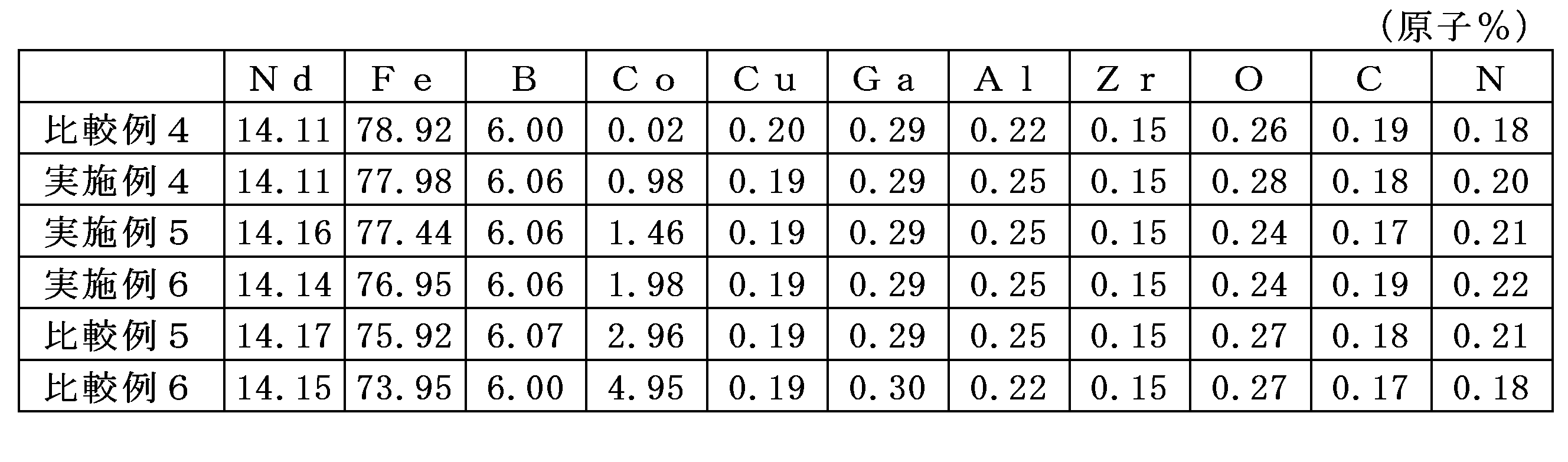

実施例4~6と比較例4~6とを比較考察すると、式(3)の条件を満たす場合、R金属相は確認されず重量減少もほとんど見られず、高いBrとHcJが得られていることが分かる。一方で[RGB]/[M1]の値が2.4以上である場合(比較例4)、R金属相の割合も高く重量減少率も高いことから耐食性が損なわれる結果となっていることが分かる。また、[RGB]/[M1]の値が1.0以下である場合(比較例5、6)、HcJが低下していることが分かる。 A comparative study of Examples 4 to 6 and Comparative Examples 4 to 6 reveals that when the condition of formula (3) is satisfied, no R metal phase is observed, almost no weight loss is observed, and high B r and H cJ are obtained. On the other hand, when the value of [R GB ]/[M1] is 2.4 or more (Comparative Example 4), the proportion of the R metal phase is high and the weight loss rate is also high, resulting in a loss of corrosion resistance. Also, when the value of [R GB ]/[M1] is 1.0 or less (Comparative Examples 5 and 6), H cJ is reduced.
[実施例7~12、比較例7]
実施例1と同様な手順で磁石の作製を行った。得られた各磁石について、ICP-OESを使用して金属成分分析を行い、また酸素濃度については不活性ガス融解赤外吸収法、窒素濃度については不活性ガス融解熱伝導法、炭素濃度については燃焼赤外吸収法により、それぞれ測定した。結果を表5に示す。また、実施例1と同様にしてR金属相の割合、耐食性評価試験での重量減少率を算出した。結果を表6に示す。なお、表6においても、本発明で規定する関係式(3)及び(4)の計算値を示す。なお、実施例7~12及び比較例7では粒界拡散処理をしておらず、磁石表面から内部にかけて濃度分布の変化はないと推定されるため、表面からの深さ0.1~200μmの範囲におけるR、Fe、Co、Cu、Gaの平均組成は、上記ICP-OES分析で求めた磁石全体に含まれる金属元素の含有率で代用し、またその領域は、磁石全面とした。
[Examples 7 to 12, Comparative Example 7]
Magnets were produced in the same manner as in Example 1. For each magnet obtained, metal component analysis was performed using ICP-OES, and the oxygen concentration was measured by inert gas fusion infrared absorption, the nitrogen concentration by inert gas fusion thermal conduction, and the carbon concentration by combustion infrared absorption. The results are shown in Table 5. The proportion of R metal phase and the weight loss rate in the corrosion resistance evaluation test were calculated in the same manner as in Example 1. The results are shown in Table 6. Table 6 also shows the calculated values of the relational expressions (3) and (4) defined in the present invention. Note that in Examples 7 to 12 and Comparative Example 7, grain boundary diffusion treatment was not performed, and it is estimated that there is no change in the concentration distribution from the magnet surface to the inside. Therefore, the average composition of R, Fe, Co, Cu, and Ga in the range of 0.1 to 200 μm deep from the surface was substituted with the content of metal elements contained in the entire magnet determined by the ICP-OES analysis, and the region was the entire magnet surface.
得られた磁石の平均結晶粒径[μm]をレーザー顕微鏡にて測定を行ったところ、実施例7~12、比較例7いずれも3.5μmであった。 The average crystal grain size [μm] of the resulting magnets was measured using a laser microscope, and was 3.5 μm for all of Examples 7 to 12 and Comparative Example 7.

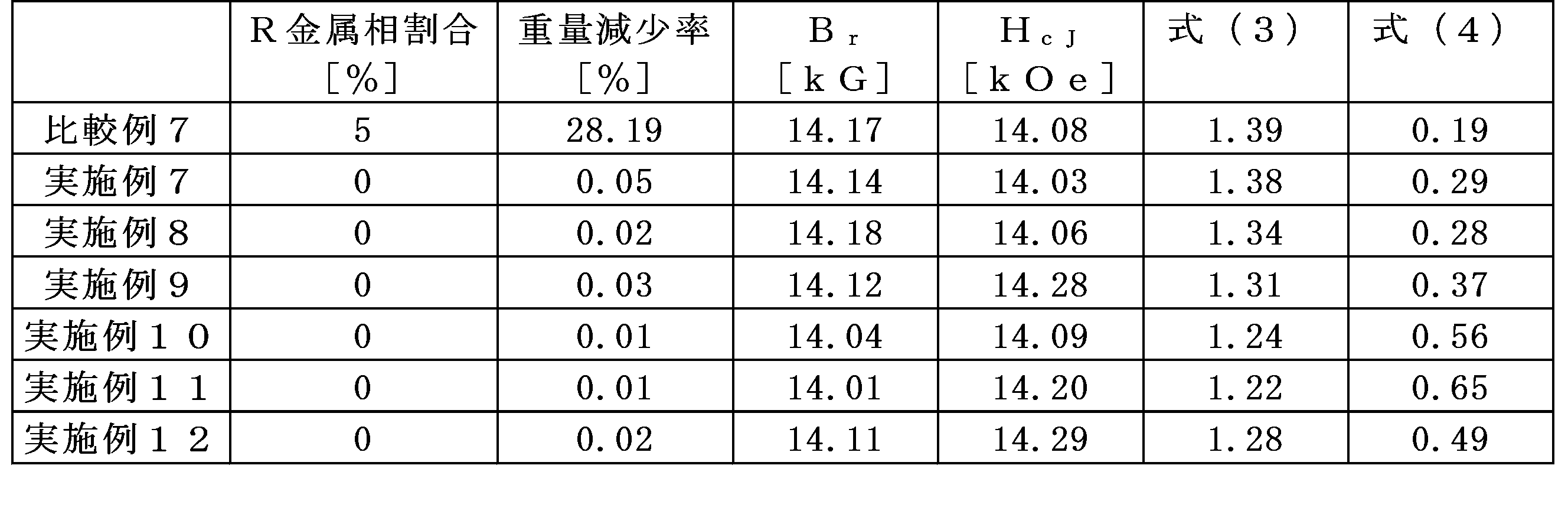
実施例7~12と比較例7とを比較考察すると、いずれの磁石も式(3)の関係は満たしている。しかし、式(4)の関係を満たしていない比較例7においては、R金属相の割合が高く重量減少率も高い。これはRとCu、Gaの化合物形成が促進されず、R金属相の形成を抑制できずに招いた結果だと考えられる。 When comparing Examples 7 to 12 with Comparative Example 7, all magnets satisfy the relationship of formula (3). However, Comparative Example 7, which does not satisfy the relationship of formula (4), has a high proportion of the R metal phase and a high weight loss rate. This is thought to be the result of the formation of compounds between R, Cu, and Ga not being promoted, leading to the formation of the R metal phase not being suppressed.
[実施例13、14]
Tbメタル、電解鉄、電解コバルト、Gaメタルを原子比でそれぞれ1:1:1となるように秤量、配合し、それら原料をアーク溶解炉で溶解してTbFeGa、TbFeCo合金インゴットを得た後、これらの合金インゴットを1050℃で10時間、真空雰囲気中で熱処理を行った。熱処理を行った合金インゴットをボールミルで粉砕し、D50が約10μmの合金粉末を調整し、合金粉末を水溶性PVA樹脂スラリーと7:3の比で混合、撹拌後、50μmの厚みに成形し、乾燥させることでTbFeGa合金シート、TbFeCo合金シートを作製した。
[Examples 13 and 14]
Tb metal, electrolytic iron, electrolytic cobalt, and Ga metal were weighed and mixed in an atomic ratio of 1:1:1, and the raw materials were melted in an arc melting furnace to obtain TbFeGa and TbFeCo alloy ingots. These alloy ingots were then heat-treated in a vacuum atmosphere at 1050° C. for 10 hours. The heat-treated alloy ingots were pulverized in a ball mill to prepare alloy powder with a D50 of about 10 μm. The alloy powder was mixed with a water-soluble PVA resin slurry in a ratio of 7:3, stirred, molded to a thickness of 50 μm, and dried to produce TbFeGa alloy sheets and TbFeCo alloy sheets.
次に、比較例1と同様の磁石を作製した。得られた磁石をL17mm×W19mm×T2.2mmに加工し、磁化方向に垂直なLW面にTbFeGa合金シート(実施例13)、及びTbFeCo合金シート(実施例14)を磁化方向に対して垂直な2面に貼り付け、900℃で20時間真空雰囲気中に保持した後300℃まで徐冷した。その後450℃まで昇温し2時間保持後、300℃まで急冷した。得られた磁石の拡散面における表面から0.1~200μmの深さの平均組成を波長分散型X線分析(WDS)により求めるため、作製した磁石のうち拡散処理を行わなかった基材の中心部をビーム径50μmの条件でWDSにより10ヶ所の測定を実施し、その値の平均分析値、及び基材のICP分析値をもとにWDS測定値の補正値を決定した。結果を表7に示す。 Next, a magnet similar to that of Comparative Example 1 was produced. The obtained magnet was processed to L 17 mm x W 19 mm x T 2.2 mm, and a TbFeGa alloy sheet (Example 13) and a TbFeCo alloy sheet (Example 14) were attached to the LW surface perpendicular to the magnetization direction, and the magnet was held in a vacuum atmosphere at 900°C for 20 hours, and then slowly cooled to 300°C. The temperature was then raised to 450°C, held for 2 hours, and then rapidly cooled to 300°C. In order to determine the average composition of the diffusion surface of the obtained magnet at a depth of 0.1 to 200 μm from the surface by wavelength dispersive X-ray analysis (WDS), 10 points were measured by WDS at the center of the substrate that was not subjected to diffusion treatment among the produced magnets under conditions of a beam diameter of 50 μm, and the correction value of the WDS measurement value was determined based on the average analysis value of the values and the ICP analysis value of the substrate. The results are shown in Table 7.
続いて、得られた磁石の拡散面における表面から0.1~200μmの深さの平均組成を求めるため、拡散面から125μm深さの位置をビーム径50μmの条件でWDSにより10ヶ所測定したものを平均し、表7の補正値をもとに補正を行い[RGB]/[M1]を算出した。その結果を表8に示す。また、実施例1と同様にしてR金属相の割合、耐食性評価試験での重量減少率を算出した。その結果を表8に示す。また、SR/Sの算出方法について、Sは粒界拡散時のT2.2mmと耐食性評価のために切り出した形状であるL5mm×W5mmの直方体として表面積を算出し、SRはその形状のうち拡散面であるL5mm×W5mmの2面分の和として算出した。その結果を表8に示す。なお表8には、上記表2に記載の比較例1の測定結果を転載した。 Next, in order to obtain the average composition at a depth of 0.1 to 200 μm from the surface of the diffusion surface of the obtained magnet, 10 positions at a depth of 125 μm from the diffusion surface were measured by WDS under the condition of a beam diameter of 50 μm, and the average was calculated by performing correction based on the correction value in Table 7 to calculate [R GB ]/[M1]. The results are shown in Table 8. In addition, the proportion of R metal phase and the weight loss rate in the corrosion resistance evaluation test were calculated in the same manner as in Example 1. The results are shown in Table 8. In addition, regarding the calculation method of S R /S, the surface area of S was calculated as T2.2 mm at the time of grain boundary diffusion and a rectangular parallelepiped of L5 mm x W5 mm, which is the shape cut out for corrosion resistance evaluation, and S R was calculated as the sum of the two faces of L5 mm x W5 mm, which are the diffusion surface of that shape. The results are shown in Table 8. In Table 8, the measurement results of Comparative Example 1 described in Table 2 above are reproduced.
なお、得られた磁石の平均結晶粒径[μm]をレーザー顕微鏡にて測定を行ったところ、実施例13、実施例14いずれも3.5μmであった。 The average crystal grain size [μm] of the resulting magnets was measured using a laser microscope and was 3.5 μm for both Example 13 and Example 14.


比較例1と実施例13、14とを比較考察すると、基材(比較例1)では耐食性を満足しなかったが、粒界拡散処理を施すことで耐食性が向上しているのが分かる。これは拡散源に含まれるGa及びCoが基材の中に導入されることで、粒界拡散前後で[RGB]/[M1]の計算値が変わり、耐食性が向上したと考えられる。また、実施例13,14ではSR/Sの値は式(5)の関係を満たしており、磁石表面積に対して十分な高耐食性領域を有しているため、十分な耐食性を有していると考えられる。 A comparison of Comparative Example 1 with Examples 13 and 14 reveals that the base material (Comparative Example 1) did not satisfy the corrosion resistance, but that the corrosion resistance was improved by carrying out the grain boundary diffusion treatment. This is thought to be because the Ga and Co contained in the diffusion source are introduced into the base material, changing the calculated value of [R GB ]/[M1] before and after the grain boundary diffusion, improving the corrosion resistance. Furthermore, in Examples 13 and 14, the value of S R /S satisfies the relationship of formula (5), and since there is a sufficient high corrosion resistance region relative to the magnet surface area, it is thought that there is sufficient corrosion resistance.
上記実施例1~14及び比較例1~7における[RGB]/[M1]と重量減少率の関係を表したものを図1に示す。この図において実施例を●、比較例を▲で示した。この図から[RGB]/[M1]の値が2.4以上の場合、耐食性が悪くなることが分かる。一方[RGB]/[M1]の値が1.0以下では、耐食性は良好であるものの、磁気特性が悪化する結果となった(比較例5、6)。また、[RGB]/[M1]の値が式(3)を満足していても式(4)を満足していない場合、耐食性が悪化する結果となった(比較例7)。 The relationship between [R GB ]/[M1] and the weight loss rate in Examples 1 to 14 and Comparative Examples 1 to 7 is shown in Figure 1. In this figure, Examples are indicated with a black circle, and Comparative Examples are indicated with a black triangle. It can be seen from this figure that when the value of [R GB ]/[M1] is 2.4 or more, corrosion resistance is poor. On the other hand, when the value of [R GB ]/[M1] is 1.0 or less, corrosion resistance is good, but the magnetic properties are poor (Comparative Examples 5 and 6). Furthermore, even if the value of [R GB ]/[M1] satisfies formula (3), when formula (4) is not satisfied, corrosion resistance is poor (Comparative Example 7).
また、粒界拡散処理を施した場合は(実施例13、14)、拡散源に含まれるM1元素の導入により、式(3)を満足しなかった基材(比較例1)の[RGB]/[M1]の値が小さくなり2.4以下となることで、十分な耐食性を獲得できることが確認された。 Furthermore, when grain boundary diffusion treatment was performed (Examples 13 and 14), it was confirmed that the introduction of the M1 element contained in the diffusion source reduced the value of [R GB ]/[M1] of the base material (Comparative Example 1) that did not satisfy equation (3) to 2.4 or less, thereby achieving sufficient corrosion resistance.
以上のとおり、本発明の要件を満足する実施例1~14の磁石は耐食性評価試験による重量減少がほとんど見られず、高い磁気特性と十分な耐食性を有するものである。 As described above, the magnets of Examples 1 to 14, which satisfy the requirements of the present invention, showed almost no weight loss in the corrosion resistance evaluation test, and possess high magnetic properties and sufficient corrosion resistance.
Claims (9)
前記Oの含有量が0.6原子%以下であり、
R2Fe14B金属間化合物である複数の主相粒子と、少なくとも二つの前記主相粒子の間に位置し、かつ前記Rを含有する粒界相とを有し、
磁石表面から深さ0.1~200μmの範囲の内の少なくとも一部に、R、Fe、Co、Cu、Ga、M1の原子百分率をそれぞれ[R]、[Fe]、[Co]、[Cu]、[Ga]、[M1]とし、前記粒界相の形成に寄与するRの原子百分率を[RGB]とした場合に、下記の関係式(1)~(4)を満足する領域を有することを特徴とする希土類焼結磁石。
[RGB]=[R]-[Fe]/7 ・・・(1)
[M1]=[Co]+[Cu]+[Ga]・・・(2)
1.0<[RGB]/[M1]<2.4 ・・・(3)
[Cu]+[Ga]≧0.28 ・・・(4) A rare earth sintered magnet comprising R (R is one or more elements selected from rare earth elements, and Nd is essential), Fe, B, M1 (M1 is two or more elements selected from Co, Cu, and Ga, and Co is essential), M2 (M2 is one or more elements selected from Al, Si, Cr, Mn, Zn, Ge, Mo, Sn, W, Pb, and Bi), and O,
The content of O is 0.6 atomic % or less,
The alloy has a plurality of main phase grains which are an R2Fe14B intermetallic compound, and a grain boundary phase which is located between at least two of the main phase grains and contains the R,
A rare earth sintered magnet characterized in that at least a portion of a range of 0.1 to 200 μm deep from the magnet surface has a region that satisfies the following relationship expressions (1) to (4), when the atomic percentages of R, Fe, Co, Cu, Ga, and M1 are [R], [Fe], [Co], [Cu], [Ga], and [M1], respectively, and the atomic percentage of R contributing to the formation of the grain boundary phase is [R GB ].
[ RGB ]=[R]-[Fe]/7...(1)
[M1]=[Co]+[Cu]+[Ga]...(2)
1.0<[ RGB ]/[M1]<2.4...(3)
[Cu]+[Ga]≧0.28...(4)
0.53≦SR/S≦1 ・・・(5) The rare earth sintered magnet according to claim 1, characterized in that the following relational expression (5) is satisfied, where S is the surface area of the magnet, and S R is the area obtained by projecting the region that satisfies the relational expressions (1) to (4) within a depth range of 0.1 to 200 μm from the magnet surface onto the adjacent magnet surface.
0.53≦S R /S≦1 (5)
[B]-2×[M3]≧[Fe]/14 ・・・(6) 5. The rare earth sintered magnet according to claim 4, wherein the following relational expression (6) is satisfied, where the atomic percentage of B is [B] and the atomic percentage of M3 is [M3]:
[B]-2×[M3]≧[Fe]/14...(6)
[測定方法]
5mm×5mm×2mmの直方体形状に切り出した試料を、エチレングリコール:水=1:1(容量比)のエチレングリコール水混合液に浸漬させ密閉した状態に120℃で480時間保持し、試料の重量の減少率を測定する。 3. The rare earth sintered magnet according to claim 1, which has a weight loss rate of 1% or less as measured by the following method.
[Measurement method]
A sample cut into a rectangular parallelepiped shape of 5 mm x 5 mm x 2 mm is immersed in an ethylene glycol-water mixture of ethylene glycol:water = 1:1 (volume ratio) and kept in a sealed state at 120°C for 480 hours, and the weight loss rate of the sample is measured.
Priority Applications (5)
| Application Number | Priority Date | Filing Date | Title |
|---|---|---|---|
| EP24823361.1A EP4730367A1 (en) | 2023-06-14 | 2024-06-11 | Rare earth sintered magnet |
| JP2025527926A JPWO2024257745A1 (en) | 2023-06-14 | 2024-06-11 | |
| CN202480039098.3A CN121368810A (en) | 2023-06-14 | 2024-06-11 | Rare earth sintered magnet |
| MX2025014939A MX2025014939A (en) | 2023-06-14 | 2024-06-11 | Rare earth sintered magnet |
| KR1020267000810A KR20260022422A (en) | 2023-06-14 | 2024-06-11 | rare earth sintered magnets |
Applications Claiming Priority (2)
| Application Number | Priority Date | Filing Date | Title |
|---|---|---|---|
| JP2023097718 | 2023-06-14 | ||
| JP2023-097718 | 2023-06-14 |
Publications (1)
| Publication Number | Publication Date |
|---|---|
| WO2024257745A1 true WO2024257745A1 (en) | 2024-12-19 |
Family
ID=93852128
Family Applications (1)
| Application Number | Title | Priority Date | Filing Date |
|---|---|---|---|
| PCT/JP2024/021127 Ceased WO2024257745A1 (en) | 2023-06-14 | 2024-06-11 | Rare earth sintered magnet |
Country Status (6)
| Country | Link |
|---|---|
| EP (1) | EP4730367A1 (en) |
| JP (1) | JPWO2024257745A1 (en) |
| KR (1) | KR20260022422A (en) |
| CN (1) | CN121368810A (en) |
| MX (1) | MX2025014939A (en) |
| WO (1) | WO2024257745A1 (en) |
Citations (8)
| Publication number | Priority date | Publication date | Assignee | Title |
|---|---|---|---|---|
| JP2007300791A (en) | 2001-12-28 | 2007-11-15 | Shin Etsu Chem Co Ltd | How to use rare earth sintered magnets |
| JP2017073465A (en) * | 2015-10-07 | 2017-04-13 | Tdk株式会社 | R-T-B based sintered magnet |
| JP2018093201A (en) * | 2016-12-06 | 2018-06-14 | Tdk株式会社 | R-t-b based permanent magnet |
| JP2018093202A (en) * | 2016-12-06 | 2018-06-14 | Tdk株式会社 | R-t-b based permanent magnet |
| JP2019102708A (en) * | 2017-12-05 | 2019-06-24 | Tdk株式会社 | R-t-b based permanent magnet |
| JP2020092122A (en) * | 2018-12-03 | 2020-06-11 | Tdk株式会社 | RTB system permanent magnet |
| JP2020102551A (en) | 2018-12-21 | 2020-07-02 | 株式会社ダイドー電子 | RFeB-BASED SINTERED MAGNET AND MANUFACTURING METHOD THEREOF |
| JP2021061301A (en) | 2019-10-04 | 2021-04-15 | 大同特殊鋼株式会社 | Sintered magnet and method for manufacturing the same |
-
2024
- 2024-06-11 EP EP24823361.1A patent/EP4730367A1/en active Pending
- 2024-06-11 MX MX2025014939A patent/MX2025014939A/en unknown
- 2024-06-11 WO PCT/JP2024/021127 patent/WO2024257745A1/en not_active Ceased
- 2024-06-11 KR KR1020267000810A patent/KR20260022422A/en active Pending
- 2024-06-11 CN CN202480039098.3A patent/CN121368810A/en active Pending
- 2024-06-11 JP JP2025527926A patent/JPWO2024257745A1/ja active Pending
Patent Citations (8)
| Publication number | Priority date | Publication date | Assignee | Title |
|---|---|---|---|---|
| JP2007300791A (en) | 2001-12-28 | 2007-11-15 | Shin Etsu Chem Co Ltd | How to use rare earth sintered magnets |
| JP2017073465A (en) * | 2015-10-07 | 2017-04-13 | Tdk株式会社 | R-T-B based sintered magnet |
| JP2018093201A (en) * | 2016-12-06 | 2018-06-14 | Tdk株式会社 | R-t-b based permanent magnet |
| JP2018093202A (en) * | 2016-12-06 | 2018-06-14 | Tdk株式会社 | R-t-b based permanent magnet |
| JP2019102708A (en) * | 2017-12-05 | 2019-06-24 | Tdk株式会社 | R-t-b based permanent magnet |
| JP2020092122A (en) * | 2018-12-03 | 2020-06-11 | Tdk株式会社 | RTB system permanent magnet |
| JP2020102551A (en) | 2018-12-21 | 2020-07-02 | 株式会社ダイドー電子 | RFeB-BASED SINTERED MAGNET AND MANUFACTURING METHOD THEREOF |
| JP2021061301A (en) | 2019-10-04 | 2021-04-15 | 大同特殊鋼株式会社 | Sintered magnet and method for manufacturing the same |
Also Published As
| Publication number | Publication date |
|---|---|
| EP4730367A1 (en) | 2026-04-22 |
| KR20260022422A (en) | 2026-02-19 |
| CN121368810A (en) | 2026-01-20 |
| JPWO2024257745A1 (en) | 2024-12-19 |
| MX2025014939A (en) | 2026-02-03 |
Similar Documents
| Publication | Publication Date | Title |
|---|---|---|
| KR102394072B1 (en) | R-Fe-B TYPE SINTERED MAGNET AND METHOD FOR MAKING THE SAME | |
| CN107871581B (en) | Method for preparing R-Fe-B sintered magnet | |
| EP2388350B1 (en) | Method for producing r-t-b sintered magnet | |
| CN100594566C (en) | Functionally graded rare earth permanent magnet | |
| JP6051892B2 (en) | Method for producing RTB-based sintered magnet | |
| JP6451900B2 (en) | R-Fe-B sintered magnet and method for producing the same | |
| WO2016133071A1 (en) | Method for producing r-t-b system sintered magnet | |
| US20240212895A1 (en) | Sintered r-t-b based magnet | |
| JP7537536B2 (en) | RTB based sintered magnet | |
| JP7059995B2 (en) | RTB-based sintered magnet | |
| JP6511844B2 (en) | RTB based sintered magnet | |
| JP7243609B2 (en) | rare earth sintered magnet | |
| JP7687167B2 (en) | Manufacturing method of RTB based sintered magnet | |
| JP7582058B2 (en) | Rare earth sintered magnet and its manufacturing method | |
| CN118692769A (en) | R-T-B Series Permanent Magnets | |
| WO2024257745A1 (en) | Rare earth sintered magnet | |
| JP7476601B2 (en) | Manufacturing method of RTB based sintered magnet | |
| JP2022174820A (en) | Rare earth sintered magnet and method for producing rare earth sintered magnet | |
| JP7226281B2 (en) | rare earth sintered magnet | |
| JP7380369B2 (en) | Manufacturing method of RTB sintered magnet and alloy for diffusion | |
| WO2025248990A1 (en) | Rare earth sintered magnet and method for producing same | |
| JP2025183376A (en) | R-t-b sintered magnet | |
| JP2024072521A (en) | RTB based sintered magnet | |
| JP2024159586A (en) | RTB system sintered magnet | |
| CN114730652A (en) | R-Fe-B sintered magnet |
Legal Events
| Date | Code | Title | Description |
|---|---|---|---|
| 121 | Ep: the epo has been informed by wipo that ep was designated in this application |
Ref document number: 24823361 Country of ref document: EP Kind code of ref document: A1 |
|
| ENP | Entry into the national phase |
Ref document number: 2025527926 Country of ref document: JP Kind code of ref document: A |
|
| WWE | Wipo information: entry into national phase |
Ref document number: 202517119935 Country of ref document: IN |
|
| WWE | Wipo information: entry into national phase |
Ref document number: 2501008408 Country of ref document: TH |
|
| WWE | Wipo information: entry into national phase |
Ref document number: MX/A/2025/014939 Country of ref document: MX |
|
| WWP | Wipo information: published in national office |
Ref document number: 202517119935 Country of ref document: IN |
|
| ENP | Entry into the national phase |
Ref document number: 1020267000810 Country of ref document: KR Free format text: ST27 STATUS EVENT CODE: A-0-1-A10-A15-NAP-PA0105 (AS PROVIDED BY THE NATIONAL OFFICE) |
|
| WWE | Wipo information: entry into national phase |
Ref document number: 1020267000810 Country of ref document: KR |
|
| WWE | Wipo information: entry into national phase |
Ref document number: 2024823361 Country of ref document: EP |
|
| NENP | Non-entry into the national phase |
Ref country code: DE |
|
| ENP | Entry into the national phase |
Ref document number: 2024823361 Country of ref document: EP Effective date: 20260114 |
|
| ENP | Entry into the national phase |
Ref document number: 2024823361 Country of ref document: EP Effective date: 20260114 |
|
| ENP | Entry into the national phase |
Ref document number: 2024823361 Country of ref document: EP Effective date: 20260114 |
|
| WWP | Wipo information: published in national office |
Ref document number: MX/A/2025/014939 Country of ref document: MX |
|
| ENP | Entry into the national phase |
Ref document number: 2024823361 Country of ref document: EP Effective date: 20260114 |
|
| WWP | Wipo information: published in national office |
Ref document number: 1020267000810 Country of ref document: KR |
|
| WWP | Wipo information: published in national office |
Ref document number: 2024823361 Country of ref document: EP |