WO2024257745A1 - Aimant fritté à base de terres rares - Google Patents
Aimant fritté à base de terres rares Download PDFInfo
- Publication number
- WO2024257745A1 WO2024257745A1 PCT/JP2024/021127 JP2024021127W WO2024257745A1 WO 2024257745 A1 WO2024257745 A1 WO 2024257745A1 JP 2024021127 W JP2024021127 W JP 2024021127W WO 2024257745 A1 WO2024257745 A1 WO 2024257745A1
- Authority
- WO
- WIPO (PCT)
- Prior art keywords
- rare earth
- atomic
- earth sintered
- sintered magnet
- magnet
- Prior art date
- Legal status (The legal status is an assumption and is not a legal conclusion. Google has not performed a legal analysis and makes no representation as to the accuracy of the status listed.)
- Ceased
Links
Images
Classifications
-
- H—ELECTRICITY
- H01—ELECTRIC ELEMENTS
- H01F—MAGNETS; INDUCTANCES; TRANSFORMERS; SELECTION OF MATERIALS FOR THEIR MAGNETIC PROPERTIES
- H01F1/00—Magnets or magnetic bodies characterised by the magnetic materials therefor; Selection of materials for their magnetic properties
- H01F1/01—Magnets or magnetic bodies characterised by the magnetic materials therefor; Selection of materials for their magnetic properties of inorganic materials
- H01F1/03—Magnets or magnetic bodies characterised by the magnetic materials therefor; Selection of materials for their magnetic properties of inorganic materials characterised by their coercivity
- H01F1/032—Magnets or magnetic bodies characterised by the magnetic materials therefor; Selection of materials for their magnetic properties of inorganic materials characterised by their coercivity of hard-magnetic materials
- H01F1/04—Magnets or magnetic bodies characterised by the magnetic materials therefor; Selection of materials for their magnetic properties of inorganic materials characterised by their coercivity of hard-magnetic materials metals or alloys
- H01F1/047—Alloys characterised by their composition
- H01F1/053—Alloys characterised by their composition containing rare earth metals
- H01F1/055—Alloys characterised by their composition containing rare earth metals and magnetic transition metals, e.g. SmCo5
- H01F1/057—Alloys characterised by their composition containing rare earth metals and magnetic transition metals, e.g. SmCo5 and IIIa elements, e.g. Nd2Fe14B
- H01F1/0571—Alloys characterised by their composition containing rare earth metals and magnetic transition metals, e.g. SmCo5 and IIIa elements, e.g. Nd2Fe14B in the form of particles, e.g. rapid quenched powders or ribbon flakes
- H01F1/0575—Alloys characterised by their composition containing rare earth metals and magnetic transition metals, e.g. SmCo5 and IIIa elements, e.g. Nd2Fe14B in the form of particles, e.g. rapid quenched powders or ribbon flakes pressed, sintered or bonded together
- H01F1/0577—Alloys characterised by their composition containing rare earth metals and magnetic transition metals, e.g. SmCo5 and IIIa elements, e.g. Nd2Fe14B in the form of particles, e.g. rapid quenched powders or ribbon flakes pressed, sintered or bonded together sintered
-
- B—PERFORMING OPERATIONS; TRANSPORTING
- B22—CASTING; POWDER METALLURGY
- B22F—WORKING METALLIC POWDER; MANUFACTURE OF ARTICLES FROM METALLIC POWDER; MAKING METALLIC POWDER; APPARATUS OR DEVICES SPECIALLY ADAPTED FOR METALLIC POWDER
- B22F3/00—Manufacture of workpieces or articles from metallic powder characterised by the manner of compacting or sintering; Apparatus specially adapted therefor ; Presses and furnaces
- B22F3/10—Sintering only
-
- C—CHEMISTRY; METALLURGY
- C22—METALLURGY; FERROUS OR NON-FERROUS ALLOYS; TREATMENT OF ALLOYS OR NON-FERROUS METALS
- C22C—ALLOYS
- C22C38/00—Ferrous alloys, e.g. steel alloys
-
- C—CHEMISTRY; METALLURGY
- C22—METALLURGY; FERROUS OR NON-FERROUS ALLOYS; TREATMENT OF ALLOYS OR NON-FERROUS METALS
- C22C—ALLOYS
- C22C38/00—Ferrous alloys, e.g. steel alloys
- C22C38/001—Ferrous alloys, e.g. steel alloys containing N
-
- C—CHEMISTRY; METALLURGY
- C22—METALLURGY; FERROUS OR NON-FERROUS ALLOYS; TREATMENT OF ALLOYS OR NON-FERROUS METALS
- C22C—ALLOYS
- C22C38/00—Ferrous alloys, e.g. steel alloys
- C22C38/002—Ferrous alloys, e.g. steel alloys containing In, Mg, or other elements not provided for in one single group C22C38/001 - C22C38/60
-
- C—CHEMISTRY; METALLURGY
- C22—METALLURGY; FERROUS OR NON-FERROUS ALLOYS; TREATMENT OF ALLOYS OR NON-FERROUS METALS
- C22C—ALLOYS
- C22C38/00—Ferrous alloys, e.g. steel alloys
- C22C38/005—Ferrous alloys, e.g. steel alloys containing rare earths, i.e. Sc, Y, Lanthanides
-
- C—CHEMISTRY; METALLURGY
- C22—METALLURGY; FERROUS OR NON-FERROUS ALLOYS; TREATMENT OF ALLOYS OR NON-FERROUS METALS
- C22C—ALLOYS
- C22C38/00—Ferrous alloys, e.g. steel alloys
- C22C38/06—Ferrous alloys, e.g. steel alloys containing aluminium
-
- C—CHEMISTRY; METALLURGY
- C22—METALLURGY; FERROUS OR NON-FERROUS ALLOYS; TREATMENT OF ALLOYS OR NON-FERROUS METALS
- C22C—ALLOYS
- C22C38/00—Ferrous alloys, e.g. steel alloys
- C22C38/10—Ferrous alloys, e.g. steel alloys containing cobalt
-
- C—CHEMISTRY; METALLURGY
- C22—METALLURGY; FERROUS OR NON-FERROUS ALLOYS; TREATMENT OF ALLOYS OR NON-FERROUS METALS
- C22C—ALLOYS
- C22C38/00—Ferrous alloys, e.g. steel alloys
- C22C38/14—Ferrous alloys, e.g. steel alloys containing titanium or zirconium
-
- C—CHEMISTRY; METALLURGY
- C22—METALLURGY; FERROUS OR NON-FERROUS ALLOYS; TREATMENT OF ALLOYS OR NON-FERROUS METALS
- C22C—ALLOYS
- C22C38/00—Ferrous alloys, e.g. steel alloys
- C22C38/16—Ferrous alloys, e.g. steel alloys containing copper
-
- H—ELECTRICITY
- H01—ELECTRIC ELEMENTS
- H01F—MAGNETS; INDUCTANCES; TRANSFORMERS; SELECTION OF MATERIALS FOR THEIR MAGNETIC PROPERTIES
- H01F1/00—Magnets or magnetic bodies characterised by the magnetic materials therefor; Selection of materials for their magnetic properties
- H01F1/01—Magnets or magnetic bodies characterised by the magnetic materials therefor; Selection of materials for their magnetic properties of inorganic materials
- H01F1/03—Magnets or magnetic bodies characterised by the magnetic materials therefor; Selection of materials for their magnetic properties of inorganic materials characterised by their coercivity
- H01F1/032—Magnets or magnetic bodies characterised by the magnetic materials therefor; Selection of materials for their magnetic properties of inorganic materials characterised by their coercivity of hard-magnetic materials
- H01F1/04—Magnets or magnetic bodies characterised by the magnetic materials therefor; Selection of materials for their magnetic properties of inorganic materials characterised by their coercivity of hard-magnetic materials metals or alloys
- H01F1/047—Alloys characterised by their composition
- H01F1/053—Alloys characterised by their composition containing rare earth metals
- H01F1/055—Alloys characterised by their composition containing rare earth metals and magnetic transition metals, e.g. SmCo5
- H01F1/057—Alloys characterised by their composition containing rare earth metals and magnetic transition metals, e.g. SmCo5 and IIIa elements, e.g. Nd2Fe14B
Definitions
- the present invention relates to rare earth sintered magnets that have high magnetic properties and excellent corrosion resistance.
- Rare earth sintered magnets are essential functional materials for energy conservation and high performance, and their range of applications and production volume are expanding year by year.
- Nd-based sintered magnets in particular have high residual magnetic flux density (hereinafter also referred to as B r ), and are used in a variety of applications and environments, such as drive motors for hybrid and electric vehicles, motors for electric power steering, motors for air conditioner compressors, and voice coil motors (VCMs) for hard disk drives.
- B r residual magnetic flux density
- VCMs voice coil motors
- rare earth sintered magnets have the problem that they are susceptible to corrosion due to the rare earth element R they contain, and it is known that corrosion begins in some R-rich phases and progresses further as the main phase is removed.
- high magnetic properties are required of rare earth magnets, and it has become necessary to reduce the impurity elements contained in the magnets to the utmost, which has resulted in an increase in the effective R content of rare earth sintered magnets and a tendency for corrosion resistance to decrease.
- the magnets built into the motor are used in harsh environments where they come into direct contact with antifreeze, so it is necessary to achieve both magnetic properties and high corrosion resistance, and various methods have been proposed.
- Patent Document 1 proposes a method of forming an electric Ni plating film on the magnet surface to impart high corrosion resistance that allows it to be used underwater.
- JP 2020-102551 A (Patent Document 2) describes that by making Cu present at the grain boundaries so that there is a concentration gradient that decreases from the magnet surface toward the inside, and by providing an oxide layer at the grain boundaries in a region 0.1 to 5 ⁇ m deep from the surface, corrosion resistance in a water pump is improved.
- JP 2021-61301 A (Patent Document 3) describes that high corrosion resistance can be obtained by forming a structure in which the grain boundary phase of the magnet as a whole contains 55 mass% or more of rare earth elements, and Cu-rich regions containing 8 mass% or more of Cu account for 9 volume% or more of the grain boundary phase.
- Patent Document 2 requires the grain boundary diffusion of the Cu-containing R alloy to form a specific structure, and also requires the formation of a surface oxide layer, which increases the number of steps and leads to increased costs.
- Patent Document 3 it is necessary to form a grain boundary phase containing rare earth elements including heavy rare earth elements, Cu, and Fe or T in which part of Fe has been replaced with Co. However, it is preferable not to contain heavy rare earth elements in particular, since they have a high resource risk and are expensive.
- the present invention was made in consideration of the above problems, and aims to provide a rare earth sintered magnet that has high magnetic properties and excellent corrosion resistance by forming a specific composition region on the magnet surface.
- the inventors conducted extensive research focusing on the composition of rare earth sintered magnets, in particular the relationship between the content of R elements and M elements (Co, Cu, Ga) that contribute to the formation of grain boundary phases in specific regions near the magnet surface.
- R elements and M elements (Co, Cu, Ga) that contribute to the formation of grain boundary phases in specific regions near the magnet surface.
- M elements Co, Cu, Ga
- an intermetallic compound is formed between R and M in the grain boundary phase, causing the R metal phase to disappear, thereby improving corrosion resistance, and thus completing the present invention.
- a rare earth sintered magnet containing R (R is one or more elements selected from rare earth elements, and Nd is essential), Fe, B, M1 (M1 is two or more elements selected from Co, Cu, and Ga, and Co is essential), M2 (M2 is one or more elements selected from Al, Si, Cr, Mn, Zn, Ge, Mo, Sn, W, Pb, and Bi), and O,
- the content of O is 0.6 atomic % or less
- the alloy has a plurality of main phase grains which are an R2Fe14B intermetallic compound, and a grain boundary phase which is located between at least two of the main phase grains and contains the R
- a rare earth sintered magnet characterized in that at least a portion of a range of 0.1 to 200 ⁇ m deep from the magnet surface has a region that satisfies the following relationship expressions (1) to (4), when the atomic percentages of R, Fe, Co, Cu, Ga, and M1 are [R], [Fe
- the rare earth sintered magnet of 1 or 2 characterized in that the content of R metal phase in the grain boundary phase, in which the content of R is 50 to 70 atomic %, is 3 volume % or less. 4.
- a rare earth sintered magnet according to any one of 1 to 8, having a weight loss rate of 1% or less as measured by the following method: [Measurement method] A sample cut into a rectangular parallelepiped shape of 5 mm x 5 mm x 2 mm is immersed in an ethylene glycol-water mixture of ethylene glycol:water 1:1 (volume ratio) and kept in a sealed state at 120°C for 480 hours, and the weight loss rate of the sample is measured.
- the present invention can provide high corrosion resistance without forming a protective film through a post-treatment process, and does not necessarily require a grain boundary diffusion process using heavy rare earth elements, making it possible to obtain a rare earth sintered magnet that is also cost-effective.
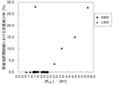
- 1 is a graph showing the relationship between the value of [R GB ]/[M1] and the weight reduction rate in the examples and comparative examples.
- the rare earth sintered magnet of the present invention contains R (R is one or more elements selected from rare earth elements, Nd is essential), Fe, B, M1 (M1 is two or more elements selected from Co, Cu, and Ga, Co is essential), M2 (M2 is one or more elements selected from Al, Si, Cr, Mn, Zn, Ge, Mo, Sn, W, Pb, and Bi), and O.
- R is one or more elements selected from rare earth elements, and Nd is essential.
- the content of R is preferably 12.5 atomic % or more, more preferably 13.0 atomic % or more, from the viewpoint of suppressing the crystallization of ⁇ -Fe in the raw alloy during production and sufficiently densifying it.
- H cJ coercive force
- the amount of liquid phase which is mainly composed of the R component and plays a role in promoting densification in the sintering process described later, decreases, so that the sinterability decreases, and it is possible to prevent insufficient densification of the R-T-B based sintered magnet.
- the content of R is preferably 17 atomic % or less, more preferably 15.5 atomic % or less, and even more preferably 15 atomic % or less.
- the proportion of Nd in R is not particularly limited, but is preferably 60 atomic % or more of all R elements, and more preferably 75 atomic % or more.
- R elements other than Nd are not particularly limited, but may preferably contain Pr, Dy, Tb, Ho, Er, Sm, Ce, Y, etc.
- the Fe content is the remainder other than the R, B, M1, M2, and O, and is preferably 70 atomic % or more, and more preferably 75 atomic % or more , from the viewpoint of obtaining a higher B r .
- the Fe content is not particularly limited, but is preferably 82 atomic % or less, and more preferably 80 atomic % or less, from the viewpoint of suppressing deterioration of squareness and decrease in H cJ due to precipitation of the R 2 T 17 phase.
- the content of B is preferably 5.0 atomic % or more, more preferably 5.5 atomic % or more, and even more preferably 5.7 atomic % or more. In such a range, the ratio of the R 2 T 14 B phase formed is low, and a significant decrease in B r and a deterioration in squareness due to the formation of the R 2 T 17 phase can be suppressed.
- the upper limit is preferably 7.0 atomic % or less, more preferably 6.5 atomic % or less, and even more preferably 6.3 atomic % or less. In such a range, it is easy to avoid the formation of the R 1.1 T 4 B 4 compound phase and the decrease in B r and H cJ .
- the above B may be partially substituted with C.
- the above M1 is two or more elements selected from Co, Cu, and Ga, and Co is essential.
- M1 is preferably 1.0 atomic % or more, and more preferably 1.5 atomic % or more. In this way, the formation of a compound between R and M1 is sufficiently carried out, the formation of a metal R phase with a high R concentration can be suppressed, and the corrosion resistance is improved.
- the upper limit is preferably 3.5 atomic % or less, and more preferably 3.0 atomic % or less. In this way, the decrease in B r and H cJ can be suppressed.
- the Co can replace part of the Fe contained in the R2T14B phase and the grain boundary phase.
- the Co content is preferably 0.5 atomic % or more of the entire magnet, and more preferably 1.0 atomic % or more.
- the Co content is preferably 3.0 atomic % or less, and more preferably 2.0 atomic % or less.
- the Cu content is preferably 0.1 atomic % or more, and more preferably 0.2 atomic % or more, of the entire magnet. From the viewpoint of stably obtaining a high B r , the Cu content is preferably 1.0 atomic % or less, and more preferably 0.5 atomic % or less.
- the Ga content is preferably 0.1 atomic % or more, and more preferably 0.2 atomic % or more, of the entire magnet. From the viewpoint of stably obtaining a high B r , the Ga content is preferably 1.0 atomic % or less, and more preferably 0.5 atomic % or less.
- M2 is one or more elements selected from Al, Si, Cr, Mn, Zn, Ge, Mo, Sn, W, Pb, and Bi.
- the content of M2 is preferably 0.1 atomic % or more, more preferably 0.2 atomic % or more, from the viewpoint of obtaining an optimal temperature range in the heat treatment for ensuring good productivity and further from the viewpoint of suppressing a decrease in HcJ .
- the content is preferably 1.5 atomic % or less, more preferably 1.0 atomic % or less.
- the O content is 0.6 atomic % or less, preferably 0.4 atomic % or less, and more preferably 0.3 atomic % or less. If the O content exceeds 0.6 atomic %, the amount of R-OCN phase or R2O3 phase formed increases, and the effective amount of R functioning as a liquid phase decreases, thereby decreasing HcJ .
- the rare earth sintered magnet of the present invention can contain optional elements other than the above-mentioned R, Fe, B, M1, M2, and O, and can contain the following M3, C, N, etc. as the above-mentioned optional elements.
- M3 is one or more elements selected from Ti, V, Zr, Nb, Hf, and Ta.
- M3 element forms M3B2 compound with B, and exhibits the effect of suppressing abnormal grain growth during sintering.
- the content of M3 is not particularly limited, but is preferably 0.1 atomic % or more, more preferably 0.2 atomic % or more, and even more preferably 0.3 atomic % or more.
- its content is preferably 2.0 atomic % or less, more preferably 1.5 atomic % or less, and even more preferably 1.0 atomic % or less.
- the atomic percentages of B and M3 are [B] and [M3]
- the C is derived from the raw material and the lubricant added to improve the orientation of the fine powder during compaction in a magnetic field, but the C derived from the lubricant is decomposed and removed in the sintering process described below, making it possible to reduce the C content compared to conventional methods.
- the C content is not particularly limited, but is preferably 0.4 atomic % or less, more preferably 0.3 atomic % or less, and even more preferably 0.2 atomic % or less.
- the N content is not particularly limited, but from the viewpoint of obtaining a good HcJ , it is preferably 0.4 atomic % or less, more preferably 0.3 atomic % or less, and even more preferably 0.2 atomic % or less.
- the structure of the rare earth sintered magnet of the present invention includes an R 2 T 14 B intermetallic compound as a main phase.
- the structure includes a plurality of main phase particles and a grain boundary phase that is located between at least two of the main phase particles and contains the R.
- the grain boundary phase may include an M3B 2 phase or the like.
- the rare earth sintered magnet of the present invention may include an R-rich phase in the grain boundary phase, and may include a phase of a compound of an inevitable impurity that is mixed in during the manufacturing process, such as R carbide, R oxide, R nitride, R halide, or R acid halide, but it is preferable to keep it to a minimum in order to suppress a decrease in B r or H cJ .
- the R metal phase with an R content in the range of 50% to 70% is highly active due to the high R concentration, and becomes the starting point of collapse by reacting with a solvent in a corrosion resistance test described later, so the proportion of the R metal phase in the entire grain boundary phase is preferably 3% by volume or less, and more preferably 1% by volume or less.
- the rare earth sintered magnet of the present invention has, in at least a portion of the range of 0.1 to 200 ⁇ m deep from its surface, a composition region (hereinafter referred to as the high corrosion resistance region) that satisfies the following relational expression (3), where the atomic percentage of M1 is [M1] and the atomic percentage of R contributing to the formation of the grain boundary phase is [R GB ]: 1.0 ⁇ [ RGB ]/[M1] ⁇ 2.4...(3)
- the composition in a region shallower than 0.1 ⁇ m from the magnet surface does not contribute to improving corrosion resistance.
- the region having this specific composition is set to a range of 0.1 to 200 ⁇ m from the magnet surface. If the grain boundary phase is insufficient in the above region near the magnet surface, [R GB ] decreases and [R GB ]/[M1] also decreases, and good H cJ cannot be obtained. Furthermore, if an excess of M1 element is present in the above region near the magnet surface, [R GB ]/[M1] decreases and B r and H cJ decrease.
- [R GB ]/[M1] is greater than 1.0 and greater than 1.2.
- [R GB ] and [R GB ]/[M1] increase, and an R metal phase with a high R concentration precipitates in that region, thereby reducing corrosion resistance.
- the M1 concentration in the above region near the magnet surface decreases, [R GB ]/[M1] increases, and the amount of M1 that forms a compound with R is insufficient, causing the R metal phase with a high R concentration to precipitate and reducing corrosion resistance.
- [R GB ]/[M1] is smaller than 2.4, and more preferably smaller than 2.2.
- the following relational expression (4) is further satisfied in the highly corrosion-resistant region.
- the value of [Cu]+[Ga] is 0.28 or more, and more preferably 0.35 or more, from the viewpoint of obtaining an optimum temperature range in the heat treatment for ensuring good productivity and from the viewpoint of obtaining an effect of improving corrosion resistance.
- the upper limit is not particularly limited, but is preferably 1.50 or less, and more preferably 1.00 or less, from the viewpoint of stably obtaining a high Br .
- some of the R, Fe, Co, Cu, and Ga in the highly corrosion-resistant region near the magnet surface may be introduced by grain boundary diffusion.
- the average composition of R, Fe, Co, Cu, and Ga in the highly corrosion-resistant region from the surface to a depth of 0.1 to 200 ⁇ m can be confirmed by using compositional analysis methods such as energy dispersive X-ray spectroscopy (EDS), wavelength dispersive X-ray analysis (WDS), and glow discharge mass spectrometry (GDMS) normalized by ICP analysis values.
- EDS energy dispersive X-ray spectroscopy
- WDS wavelength dispersive X-ray analysis
- GDMS glow discharge mass spectrometry
- the rare earth sintered magnet does not have a change in concentration distribution of each element from the magnet surface to the inside due to the application of a grain boundary diffusion method, etc.
- the average composition of R, Fe, Co, Cu, and Ga in the highly corrosion-resistant region from the surface to a depth of 0.1 to 200 ⁇ m of the rare earth sintered magnet can be substituted with the content of metal elements contained in the entire magnet determined by ICP analysis.
- the rare earth sintered magnet of the present invention has a region (high corrosion resistance region) whose average composition satisfies the above relational expression (3) in at least a part of the range of 0.1 to 200 ⁇ m deep from the surface.
- the rare earth sintered magnet of the present invention has the above high corrosion resistance region near the magnet surface, which improves its corrosion resistance, and since the larger the high corrosion resistance region is relative to the magnet surface area, the higher the corrosion resistance can be obtained, it is preferable to satisfy the following relational expression, where S is the surface area of the magnet and S R is the area obtained by projecting the high corrosion resistance region onto the adjacent magnet surface. 0.53 ⁇ S R /S ⁇ 1...(5) It is more preferable that S R /S is 0.6 or more.
- S R /S is a maximum of 1 when various elements are supplied from the entire surface of the magnet, and in the case where grain boundary diffusion is not performed, it is a maximum of 1 when the content of metal elements contained in the entire magnet satisfies the relational expression (3).
- S R for example, for magnets in which grain boundary diffusion is performed under the same conditions only from two opposing surfaces, the average composition of any region within a depth range of 0.1 to 200 ⁇ m from the surface of the diffusion surface can be treated as a representative value including the opposing diffusion surface.
- the ICP analysis composition of the base material to which the grain boundary diffusion treatment is performed can be used as a representative value.
- the method for obtaining S R is not particularly limited, but from the viewpoint of simplicity, it is preferable to use WDS (Wave-length Dispersive X-ray Spectroscopy).
- WDS Wide-length Dispersive X-ray Spectroscopy
- the beam diameter during WDS measurement is preferably sufficiently larger than the average crystal grain size of the magnet to be measured in order to obtain the average composition of the structure including multiple main phases, grain boundary phases, and grain boundary triple junctions, for example, 30 ⁇ m or more, more preferably 50 ⁇ m or more.
- the magnet is divided into 2 mm x 2 mm x 2 mm to 1 mm x 1 mm x 1 mm by cutting or the like, and the magnet after division is analyzed to obtain S R , and the area lost by cutting or the like can be deducted in advance from the magnet surface area S.
- the corrosion resistance of the present invention can be evaluated by the following method.
- the magnet is then removed, degreased with ethanol, ultrasonically cleaned in water, dried, and the weight of the magnet is measured to obtain the post-test weight.
- the weight loss rate due to the corrosion resistance test obtained by the above method is preferably 1% or less, and more preferably 0.5% or less, from the viewpoint of maintaining good magnetic properties even after the test.
- the average crystal grain size ( ⁇ m) in the plane parallel to the magnetization direction of the rare earth sintered magnet of the present invention is preferably 4 ⁇ m or less, more preferably 3.5 ⁇ m or less, from the viewpoint of improving corrosion resistance by reducing the effect of weight loss caused by the shedding of the main phase due to the collapse of the grain boundary phase in a corrosion resistance test, and obtaining sufficient H cJ .
- the lower limit of this average crystal grain size ( ⁇ m) is preferably 1.2 ⁇ m or more, more preferably 1.8 ⁇ m or more, from the viewpoint of obtaining a sufficient degree of orientation within an appropriate range of the amount of lubricant added.
- the average crystal grain size in the present invention is defined as the area median diameter obtained from a histogram showing the particle size distribution in which the ratio of the area occupied by crystal grains for every 1 ⁇ m average particle interval is plotted for the circle equivalent diameter of each particle.
- the area median diameter can be calculated by creating a histogram of the crystal grain area ratio from the diameter of each particle calculated as the circle equivalent diameter and fitting it with a Gaussian function.
- the circle equivalent diameter of the above-mentioned particles can be measured, for example, by the following procedure.
- the cross-sectional area of each particle is measured by image analysis, and the diameter as an equivalent circle is calculated.
- the average crystal grain size may be, for example, the average of a total of about 2,000 particles in 20 different images.
- the measurement device is not particularly limited, but for example, a 3D measuring laser microscope (LEXT OLS 4000, manufactured by Olympus Corporation) can be used, and image analysis software (Win ROOF, manufactured by Mitani Shoji Co., Ltd.) can be used for image analysis.
- a 3D measuring laser microscope LEXT OLS 4000, manufactured by Olympus Corporation
- image analysis software Win ROOF, manufactured by Mitani Shoji Co., Ltd.
- the rare earth sintered magnet of the present invention is preferably produced in a process that reduces the amount of impurity elements contained to the utmost limit.
- the formation of compounds between the impurity elements and R is not promoted, and an R metal phase with a high R concentration is more likely to form.
- This R metal phase has a low corrosion potential and is therefore likely to become the starting point for corrosion, resulting in weight loss and reduced magnetic properties.
- Methods for suppressing the formation of the R metal phase include reducing the R content and including an element other than the impurity elements that is likely to form a compound with R.
- the element added in the latter method is the above-mentioned M1, and by adjusting the content of this M1 to an appropriate range as described above, it is possible to achieve high magnetic properties and excellent corrosion resistance.
- the process for manufacturing the rare earth sintered magnet of the present invention includes a melting step in which the raw material is melted to obtain a raw material alloy having a predetermined composition, a crushing step in which the raw material alloy is crushed to prepare an alloy fine powder, a molding step in which the alloy fine powder is compressed under an applied magnetic field to obtain a green body, and a sintering step in which the green body is heat-treated to obtain a sintered body.
- the metal or alloy that is the raw material of each element is weighed to obtain a predetermined composition.
- the raw material is melted by, for example, high-frequency melting, and cooled to produce a raw alloy.
- the casting of the raw alloy is generally performed by melting and casting into a flat mold or a book mold, or by strip casting.
- the present invention can also be applied to a so-called two-alloy method in which an alloy close to the main phase R 2 Fe 14 B compound composition and an R-rich alloy that becomes a liquid phase auxiliary at the sintering temperature are separately prepared, and then weighed and mixed after coarse grinding.
- an alloy close to the main phase composition is likely to crystallize out of the ⁇ -Fe phase depending on the cooling rate and alloy composition during casting, it is preferable to perform a homogenization treatment for 1 hour or more in a vacuum or Ar atmosphere as necessary in order to homogenize the structure and eliminate the ⁇ -Fe phase.
- a homogenization treatment for 1 hour or more in a vacuum or Ar atmosphere, homogenization can be omitted.
- an R-rich alloy that serves as a liquid phase assistant in addition to the above-mentioned casting method, the so-called liquid quenching method can also be applied.
- the above-mentioned crushing process is a multi-stage process including at least a coarse crushing process and a fine crushing process.
- a coarse crushing process for example, a jaw crusher, a Braun mill, a pin mill, or hydrogen crushing can be used as appropriate.
- a hydrogen crushing process is a crushing process by hydrogen absorption in which the alloy is absorbed by exposing the alloy block to a hydrogen atmosphere of a certain pressure or more.
- the hydrogen pressure at this time is not particularly limited, but from the viewpoint of reducing the adverse effect on productivity due to the time required for hydrogen absorption, it is preferable that it is 100 kPa or more.
- dehydrogenation treatment may be performed as necessary.
- the alloy block with an increased temperature is cooled and transported to the next process. At this time, it is preferable to cool it to around room temperature from the viewpoint of preventing oxidation.
- the coarse powder obtained in the coarse pulverization step can be pulverized using a jet mill using a non-oxidizing gas stream such as N 2 , He, or Ar.
- the coarse powder in this fine pulverization step, is pulverized to a volume-based median diameter D50 of preferably 0.2 ⁇ m to 10 ⁇ m, more preferably 1.2 ⁇ m to 4.0 ⁇ m, and even more preferably 1.5 to 3.5 ⁇ m. Since O and N in the rare earth sintered magnet are mainly mixed in during the fine pulverization step, it is necessary to control the jet mill atmosphere in order to adjust the O and N contents in the rare earth sintered magnet.
- the O content in the rare earth sintered magnet is adjusted by controlling the O amount and dew point in the jet mill atmosphere, and the moisture content in the atmosphere during pulverization is preferably 100 ppm or less, and the oxygen concentration is preferably 1 ppm or less.
- the volume-based median diameter D50 is the particle diameter when the cumulative volume frequency is 50%.
- the N content in the rare earth sintered magnet can be adjusted, for example, by (A) a method of pulverizing the magnet in a jet mill using a He or Ar gas stream, (B) a method of pulverizing the magnet by introducing hydrogen into a jet mill using a N2 gas stream, or (C) a method of pulverizing the magnet in a jet mill using a hydrogen-containing coarse powder using a N2 gas stream.
- hydrogen is preferentially adsorbed onto the active surface generated by pulverization by introducing hydrogen gas or using a coarse powder using hydrogen, and the adsorption of nitrogen is inhibited, thereby making it possible to reduce the amount of N in the rare earth sintered magnet.
- the hydrogen-containing coarse powder in method (C) above can be prepared, for example, by omitting the dehydrogenation process in the hydrogen crushing step, by absorbing hydrogen into the coarse powder after the dehydrogenation process, or by absorbing hydrogen into the coarse powder obtained by mechanical crushing in a He or Ar gas atmosphere.
- the hydrogen content of the coarse powder or the fine powder after crushing is preferably 0.1 to 1.0 mass%, and more preferably 0.2 to 0.5 mass%.
- the hydrogen content of the coarse powder or the fine powder after crushing can be determined by measuring the change in weight before and after hydrogen absorption.
- a lubricant consisting of, for example, a saturated fatty acid or its ester can be appropriately added before or after the above-mentioned coarse crushing step in order to improve the orientation of the powder in the next step of molding in a magnetic field.
- a lubricant is effective in improving the orientation, a dilemma arises in that many R-OCN phases are formed in the rare earth sintered magnet due to the C derived from the lubricant, and H cJ drops significantly. Therefore, in order to suppress the drop in H cJ , it is preferable to add a lubricant when the above-mentioned method (C) is adopted.
- the lubricant chemically adsorbed on the fine powder surface is decomposed by the hydrogen through a carbonyl reduction reaction or the like, and further decomposed and dissociated into a highly volatile lower alcohol through a cracking reaction by hydrogen gas, which is believed to reduce the C content remaining in the rare earth sintered magnet.
- the amount of the lubricant added is appropriately set depending on the type of lubricant, and is not particularly limited, but is preferably 0.01 to 0.50 parts by mass, and more preferably 0.05 to 0.30 parts by mass, per 100 parts by mass of the coarsely pulverized powder or raw alloy.
- a magnetic field of 400 to 1600 kA/m is applied, and the alloy powder is compacted in a compression molding machine while being oriented in the direction of the easy axis of magnetization.
- it is preferable to set the density of the compact to 2.8 to 4.2 g/cm 3. That is, from the viewpoint of ensuring the strength of the compact and obtaining good handling properties, it is preferable to set the density of the compact to 2.8 g/cm 3 or more.
- a binder such as PVA or fatty acid can be added to increase the strength of the compact after molding.
- the density of the compact is 4.2 g/cm 3 or less.
- the sintering step is a step of sintering the molded body obtained in the molding step in an inert gas atmosphere such as Ar gas or in a high vacuum, and preferably includes an atmospheric heat treatment step in which heat treatment is performed in an inert gas atmosphere, and a vacuum heat treatment step in which heat treatment is performed in a vacuum atmosphere.
- the atmospheric heat treatment step is preferably held in an inert gas atmosphere at 300 to 600°C for 1 to 10 hours, although there is no particular limit to this.
- the vacuum heat treatment step it is preferably held in a high vacuum at 950 to 1200°C for 0.5 to 10 hours, although there is no particular limit to this.
- the obtained sintered body may be subjected to a heat treatment or a grain boundary diffusion step at a temperature lower than the sintering temperature in order to increase HcJ .
- the heat treatment at a temperature lower than the sintering temperature may be a two-stage heat treatment of a high-temperature heat treatment and a low-temperature heat treatment, or only a low-temperature heat treatment may be performed.
- the sintered body is preferably heat-treated at a temperature of 600 to 950°C, and in the low-temperature heat treatment, the sintered body is preferably heat-treated at a temperature of 400 to 600°C.
- the grain boundary diffusion step may be carried out for the purpose of increasing the HcJ of the obtained sintered body and forming a highly corrosion-resistant region, and includes a diffusion source providing step of providing a diffusion source on the surface of the obtained sintered body, and a diffusion heat treatment step of heat-treating the sintered body and the diffusion source in a vacuum or inert gas atmosphere.
- the composition of the diffusion source is not particularly limited, but can be appropriately selected according to the above-mentioned purpose, for example.
- R2 is one or more elements selected from Dy and Tb
- HcJ is one or more elements selected from Co, Cu, and Ga
- M1 is one or more elements selected from Co, Cu, and Ga
- the diffusion source powder can be dispersed in an organic solvent such as alcohol or water to form a slurry, and the sintered body can be immersed in this slurry and then lifted out and dried with hot air or vacuum, or allowed to dry naturally.
- the diffusion source powder can be mixed with a resin slurry, stirred, and then formed into a sheet that can be attached to the sintered body.
- R2 is concentrated near the grain boundaries in the main phase of the magnet in order to obtain a sufficient increase in coercivity
- M1 is concentrated in a range of 0.1 to 200 ⁇ m deep from the magnet surface so as to satisfy the above-mentioned relations (3) and (5) in order to enhance corrosion resistance.
- Specific conditions are not particularly limited, but conditions are preferred where the R2 element and/or M1 element is heated to a temperature of more than 400°C, particularly 500°C or higher, and 1100°C or lower, particularly 1050°C or lower, and especially 1000°C or lower, to diffuse into the sintered body.
- the heat treatment time is preferably 1 minute to 50 hours to avoid deterioration of the structure of the sintered body and adverse effects of inevitable oxidation and evaporation of components on the magnetic properties and corrosion resistance.
- the diffusion source is applied to 53% or more of the total surface area of the magnet so that the area of the high corrosion resistance region satisfies relational expression (5).
- Examples 1 to 3 Nd metal, ferroboron alloy, electrolytic Co, Al metal, Cu metal, Ga metal, Zr metal and electrolytic iron (all metals have a purity of 99% or more) were weighed and mixed in a predetermined ratio, melted, and cast by a strip casting method to obtain a flake-shaped raw alloy having a thickness of 0.2 to 0.4 mm. The obtained flake-shaped raw alloy was subjected to hydrogen embrittlement in a hydrogen pressure atmosphere to obtain a coarsely pulverized powder.
- pulverized particle size (D50) is a volume-based median diameter obtained by a laser diffraction method using an airflow dispersion method.
- the finely pulverized powder was filled into a mold of a molding machine in a N2 gas atmosphere, and while oriented in a magnetic field of 15 kOe (1.19 MA/m), it was pressure molded in a direction perpendicular to the magnetic field.
- the density of the molded body at this time was 3.0 to 4.0 g/ cm3 .
- the obtained molded body was subjected to an atmospheric heat treatment in which the temperature was raised to 500°C in an Ar gas atmosphere and heat-treated, and then sintered in a vacuum at 1040 to 1080°C (a temperature at which sufficient densification by sintering occurs for each sample) for 5 hours to obtain a Nd magnet material.
- the density of the resulting Nd magnet was 7.5 g/cm3 or more .
- the central part of the resulting magnet was subjected to metal component analysis using inductively coupled plasma optical emission spectroscopy (ICP-OES), and the oxygen concentration was measured by inert gas fusion infrared absorption spectrometry, the nitrogen concentration by inert gas fusion thermal conductivity spectrometry, and the carbon concentration by combustion infrared absorption spectrometry.
- ICP-OES inductively coupled plasma optical emission spectroscopy
- the structure of the obtained magnet was observed using an EPMA (Electron Probe Micro Analyzer), the R metal phase was identified from the backscattered electron image and the results of semi-quantitative analysis, and the proportion of the R metal phase contained in the entire grain boundary phase of the magnet was measured using image processing. The results are shown in Table 2.
- the magnets thus obtained were cut into rectangular parallelepiped shapes measuring L 15 mm x W 7 mm x T (magnetization direction) 12 mm, and B r and H cJ were measured using a BH tracer. The results are shown in Table 2.
- Table 2 also shows the calculated values of the relational expressions (3) and (4) defined in the present invention. Note that in Examples 1 to 3 and Comparative Examples 1 to 3, grain boundary diffusion treatment was not performed, and it is presumed that there is no change in concentration distribution from the magnet surface to the inside. Therefore, the average composition of R, Fe, Co, Cu, and Ga in the range of 0.1 to 200 ⁇ m was substituted with the content of metal elements contained in the entire magnet determined by the ICP-OES analysis, and this region was defined as the entire magnet surface.
- the average crystal grain size [ ⁇ m] of the obtained magnets was measured using a laser microscope, and was found to be 3.5 ⁇ m for all of Examples 1 to 3 and Comparative Examples 1 to 3.
- Example 4 to 6 Comparative Examples 4 to 6
- Magnets were produced in the same manner as in Example 1.
- metal component analysis was performed using ICP-OES, and the oxygen concentration was measured by inert gas fusion infrared absorption, the nitrogen concentration by inert gas fusion thermal conduction, and the carbon concentration by combustion infrared absorption.
- the results are shown in Table 3.
- the proportion of R metal phase and the weight loss rate in the corrosion resistance evaluation test were calculated in the same manner as in Example 1.
- Table 4 also shows the calculated values of the relational expressions (3) and (4) defined in the present invention.
- the average crystal grain size [ ⁇ m] of the resulting magnets was measured using a laser microscope, and was 3.5 ⁇ m for all of Examples 4 to 6 and Comparative Examples 4 to 6.
- Example 7 to 12 Comparative Example 7
- Magnets were produced in the same manner as in Example 1.
- metal component analysis was performed using ICP-OES, and the oxygen concentration was measured by inert gas fusion infrared absorption, the nitrogen concentration by inert gas fusion thermal conduction, and the carbon concentration by combustion infrared absorption.
- the results are shown in Table 5.
- the proportion of R metal phase and the weight loss rate in the corrosion resistance evaluation test were calculated in the same manner as in Example 1.
- Table 6 also shows the calculated values of the relational expressions (3) and (4) defined in the present invention.
- the average crystal grain size [ ⁇ m] of the resulting magnets was measured using a laser microscope, and was 3.5 ⁇ m for all of Examples 7 to 12 and Comparative Example 7.
- Comparative Example 7 When comparing Examples 7 to 12 with Comparative Example 7, all magnets satisfy the relationship of formula (3). However, Comparative Example 7, which does not satisfy the relationship of formula (4), has a high proportion of the R metal phase and a high weight loss rate. This is thought to be the result of the formation of compounds between R, Cu, and Ga not being promoted, leading to the formation of the R metal phase not being suppressed.
- Tb metal, electrolytic iron, electrolytic cobalt, and Ga metal were weighed and mixed in an atomic ratio of 1:1:1, and the raw materials were melted in an arc melting furnace to obtain TbFeGa and TbFeCo alloy ingots. These alloy ingots were then heat-treated in a vacuum atmosphere at 1050° C. for 10 hours. The heat-treated alloy ingots were pulverized in a ball mill to prepare alloy powder with a D50 of about 10 ⁇ m. The alloy powder was mixed with a water-soluble PVA resin slurry in a ratio of 7:3, stirred, molded to a thickness of 50 ⁇ m, and dried to produce TbFeGa alloy sheets and TbFeCo alloy sheets.
- Example 13 a TbFeGa alloy sheet
- Example 14 a TbFeCo alloy sheet
- the average crystal grain size [ ⁇ m] of the resulting magnets was measured using a laser microscope and was 3.5 ⁇ m for both Example 13 and Example 14.
- Comparative Example 1 A comparison of Comparative Example 1 with Examples 13 and 14 reveals that the base material (Comparative Example 1) did not satisfy the corrosion resistance, but that the corrosion resistance was improved by carrying out the grain boundary diffusion treatment. This is thought to be because the Ga and Co contained in the diffusion source are introduced into the base material, changing the calculated value of [R GB ]/[M1] before and after the grain boundary diffusion, improving the corrosion resistance. Furthermore, in Examples 13 and 14, the value of S R /S satisfies the relationship of formula (5), and since there is a sufficient high corrosion resistance region relative to the magnet surface area, it is thought that there is sufficient corrosion resistance.
- the magnets of Examples 1 to 14 which satisfy the requirements of the present invention, showed almost no weight loss in the corrosion resistance evaluation test, and possess high magnetic properties and sufficient corrosion resistance.
Landscapes
- Chemical & Material Sciences (AREA)
- Engineering & Computer Science (AREA)
- Mechanical Engineering (AREA)
- Materials Engineering (AREA)
- Metallurgy (AREA)
- Organic Chemistry (AREA)
- Crystallography & Structural Chemistry (AREA)
- Inorganic Chemistry (AREA)
- Power Engineering (AREA)
- Manufacturing & Machinery (AREA)
- Hard Magnetic Materials (AREA)
Abstract
Priority Applications (5)
| Application Number | Priority Date | Filing Date | Title |
|---|---|---|---|
| EP24823361.1A EP4730367A1 (fr) | 2023-06-14 | 2024-06-11 | Aimant fritté à base de terres rares |
| JP2025527926A JPWO2024257745A1 (fr) | 2023-06-14 | 2024-06-11 | |
| CN202480039098.3A CN121368810A (zh) | 2023-06-14 | 2024-06-11 | 稀土烧结磁铁 |
| MX2025014939A MX2025014939A (es) | 2023-06-14 | 2024-06-11 | Iman sinterizado de tierras raras |
| KR1020267000810A KR20260022422A (ko) | 2023-06-14 | 2024-06-11 | 희토류 소결 자석 |
Applications Claiming Priority (2)
| Application Number | Priority Date | Filing Date | Title |
|---|---|---|---|
| JP2023097718 | 2023-06-14 | ||
| JP2023-097718 | 2023-06-14 |
Publications (1)
| Publication Number | Publication Date |
|---|---|
| WO2024257745A1 true WO2024257745A1 (fr) | 2024-12-19 |
Family
ID=93852128
Family Applications (1)
| Application Number | Title | Priority Date | Filing Date |
|---|---|---|---|
| PCT/JP2024/021127 Ceased WO2024257745A1 (fr) | 2023-06-14 | 2024-06-11 | Aimant fritté à base de terres rares |
Country Status (6)
| Country | Link |
|---|---|
| EP (1) | EP4730367A1 (fr) |
| JP (1) | JPWO2024257745A1 (fr) |
| KR (1) | KR20260022422A (fr) |
| CN (1) | CN121368810A (fr) |
| MX (1) | MX2025014939A (fr) |
| WO (1) | WO2024257745A1 (fr) |
Citations (8)
| Publication number | Priority date | Publication date | Assignee | Title |
|---|---|---|---|---|
| JP2007300791A (ja) | 2001-12-28 | 2007-11-15 | Shin Etsu Chem Co Ltd | 希土類焼結磁石の使用方法 |
| JP2017073465A (ja) * | 2015-10-07 | 2017-04-13 | Tdk株式会社 | R−t−b系焼結磁石 |
| JP2018093201A (ja) * | 2016-12-06 | 2018-06-14 | Tdk株式会社 | R−t−b系永久磁石 |
| JP2018093202A (ja) * | 2016-12-06 | 2018-06-14 | Tdk株式会社 | R−t−b系永久磁石 |
| JP2019102708A (ja) * | 2017-12-05 | 2019-06-24 | Tdk株式会社 | R−t−b系永久磁石 |
| JP2020092122A (ja) * | 2018-12-03 | 2020-06-11 | Tdk株式会社 | R‐t‐b系永久磁石 |
| JP2020102551A (ja) | 2018-12-21 | 2020-07-02 | 株式会社ダイドー電子 | RFeB系焼結磁石及びその製造方法 |
| JP2021061301A (ja) | 2019-10-04 | 2021-04-15 | 大同特殊鋼株式会社 | 焼結磁石および焼結磁石の製造方法 |
-
2024
- 2024-06-11 EP EP24823361.1A patent/EP4730367A1/fr active Pending
- 2024-06-11 MX MX2025014939A patent/MX2025014939A/es unknown
- 2024-06-11 WO PCT/JP2024/021127 patent/WO2024257745A1/fr not_active Ceased
- 2024-06-11 KR KR1020267000810A patent/KR20260022422A/ko active Pending
- 2024-06-11 CN CN202480039098.3A patent/CN121368810A/zh active Pending
- 2024-06-11 JP JP2025527926A patent/JPWO2024257745A1/ja active Pending
Patent Citations (8)
| Publication number | Priority date | Publication date | Assignee | Title |
|---|---|---|---|---|
| JP2007300791A (ja) | 2001-12-28 | 2007-11-15 | Shin Etsu Chem Co Ltd | 希土類焼結磁石の使用方法 |
| JP2017073465A (ja) * | 2015-10-07 | 2017-04-13 | Tdk株式会社 | R−t−b系焼結磁石 |
| JP2018093201A (ja) * | 2016-12-06 | 2018-06-14 | Tdk株式会社 | R−t−b系永久磁石 |
| JP2018093202A (ja) * | 2016-12-06 | 2018-06-14 | Tdk株式会社 | R−t−b系永久磁石 |
| JP2019102708A (ja) * | 2017-12-05 | 2019-06-24 | Tdk株式会社 | R−t−b系永久磁石 |
| JP2020092122A (ja) * | 2018-12-03 | 2020-06-11 | Tdk株式会社 | R‐t‐b系永久磁石 |
| JP2020102551A (ja) | 2018-12-21 | 2020-07-02 | 株式会社ダイドー電子 | RFeB系焼結磁石及びその製造方法 |
| JP2021061301A (ja) | 2019-10-04 | 2021-04-15 | 大同特殊鋼株式会社 | 焼結磁石および焼結磁石の製造方法 |
Also Published As
| Publication number | Publication date |
|---|---|
| EP4730367A1 (fr) | 2026-04-22 |
| KR20260022422A (ko) | 2026-02-19 |
| CN121368810A (zh) | 2026-01-20 |
| JPWO2024257745A1 (fr) | 2024-12-19 |
| MX2025014939A (es) | 2026-02-03 |
Similar Documents
| Publication | Publication Date | Title |
|---|---|---|
| KR102394072B1 (ko) | R―Fe―B계 소결 자석 및 그의 제조 방법 | |
| CN107871581B (zh) | 制备R-Fe-B烧结磁体的方法 | |
| EP2388350B1 (fr) | Procédé de production d'aimant fritté r-t-b | |
| CN100594566C (zh) | 功能梯度稀土永磁体 | |
| JP6051892B2 (ja) | R−t−b系焼結磁石の製造方法 | |
| JP6451900B2 (ja) | R−Fe−B系焼結磁石及びその製造方法 | |
| WO2016133071A1 (fr) | Procédé de fabrication d'aimant fritté du système r-t-b | |
| US20240212895A1 (en) | Sintered r-t-b based magnet | |
| JP7537536B2 (ja) | R-t-b系焼結磁石 | |
| JP7059995B2 (ja) | R-t-b系焼結磁石 | |
| JP6511844B2 (ja) | R−t−b系焼結磁石 | |
| JP7243609B2 (ja) | 希土類焼結磁石 | |
| JP7687167B2 (ja) | R-t-b系焼結磁石の製造方法 | |
| JP7582058B2 (ja) | 希土類焼結磁石及びその製造方法 | |
| CN118692769A (zh) | R-t-b系永久磁铁 | |
| WO2024257745A1 (fr) | Aimant fritté à base de terres rares | |
| JP7476601B2 (ja) | R-t-b系焼結磁石の製造方法 | |
| JP2022174820A (ja) | 希土類焼結磁石及び希土類焼結磁石の製造方法 | |
| JP7226281B2 (ja) | 希土類焼結磁石 | |
| JP7380369B2 (ja) | R-t-b系焼結磁石の製造方法及び拡散用合金 | |
| WO2025248990A1 (fr) | Aimant fritté en terres rares et son procédé de production | |
| JP2025183376A (ja) | R-t-b系焼結磁石 | |
| JP2024072521A (ja) | R-t-b系焼結磁石 | |
| JP2024159586A (ja) | R-t-b系焼結磁石 | |
| CN114730652A (zh) | R-Fe-B系烧结磁体 |
Legal Events
| Date | Code | Title | Description |
|---|---|---|---|
| 121 | Ep: the epo has been informed by wipo that ep was designated in this application |
Ref document number: 24823361 Country of ref document: EP Kind code of ref document: A1 |
|
| ENP | Entry into the national phase |
Ref document number: 2025527926 Country of ref document: JP Kind code of ref document: A |
|
| WWE | Wipo information: entry into national phase |
Ref document number: 202517119935 Country of ref document: IN |
|
| WWE | Wipo information: entry into national phase |
Ref document number: 2501008408 Country of ref document: TH |
|
| WWE | Wipo information: entry into national phase |
Ref document number: MX/A/2025/014939 Country of ref document: MX |
|
| WWP | Wipo information: published in national office |
Ref document number: 202517119935 Country of ref document: IN |
|
| ENP | Entry into the national phase |
Ref document number: 1020267000810 Country of ref document: KR Free format text: ST27 STATUS EVENT CODE: A-0-1-A10-A15-NAP-PA0105 (AS PROVIDED BY THE NATIONAL OFFICE) |
|
| WWE | Wipo information: entry into national phase |
Ref document number: 1020267000810 Country of ref document: KR |
|
| WWE | Wipo information: entry into national phase |
Ref document number: 2024823361 Country of ref document: EP |
|
| NENP | Non-entry into the national phase |
Ref country code: DE |
|
| ENP | Entry into the national phase |
Ref document number: 2024823361 Country of ref document: EP Effective date: 20260114 |
|
| ENP | Entry into the national phase |
Ref document number: 2024823361 Country of ref document: EP Effective date: 20260114 |
|
| ENP | Entry into the national phase |
Ref document number: 2024823361 Country of ref document: EP Effective date: 20260114 |
|
| WWP | Wipo information: published in national office |
Ref document number: MX/A/2025/014939 Country of ref document: MX |
|
| ENP | Entry into the national phase |
Ref document number: 2024823361 Country of ref document: EP Effective date: 20260114 |
|
| WWP | Wipo information: published in national office |
Ref document number: 1020267000810 Country of ref document: KR |
|
| WWP | Wipo information: published in national office |
Ref document number: 2024823361 Country of ref document: EP |