WO2024257761A1 - 強化結晶化ガラス、およびその製造方法 - Google Patents
強化結晶化ガラス、およびその製造方法 Download PDFInfo
- Publication number
- WO2024257761A1 WO2024257761A1 PCT/JP2024/021191 JP2024021191W WO2024257761A1 WO 2024257761 A1 WO2024257761 A1 WO 2024257761A1 JP 2024021191 W JP2024021191 W JP 2024021191W WO 2024257761 A1 WO2024257761 A1 WO 2024257761A1
- Authority
- WO
- WIPO (PCT)
- Prior art keywords
- crystallized glass
- strengthened
- less
- layer
- ion exchange
- Prior art date
- Legal status (The legal status is an assumption and is not a legal conclusion. Google has not performed a legal analysis and makes no representation as to the accuracy of the status listed.)
- Ceased
Links
Images



Classifications
-
- C—CHEMISTRY; METALLURGY
- C03—GLASS; MINERAL OR SLAG WOOL
- C03C—CHEMICAL COMPOSITION OF GLASSES, GLAZES OR VITREOUS ENAMELS; SURFACE TREATMENT OF GLASS; SURFACE TREATMENT OF FIBRES OR FILAMENTS MADE FROM GLASS, MINERALS OR SLAGS; JOINING GLASS TO GLASS OR OTHER MATERIALS
- C03C21/00—Treatment of glass, not in the form of fibres or filaments, by diffusing ions or metals in the surface
- C03C21/001—Treatment of glass, not in the form of fibres or filaments, by diffusing ions or metals in the surface in liquid phase, e.g. molten salts, solutions
- C03C21/002—Treatment of glass, not in the form of fibres or filaments, by diffusing ions or metals in the surface in liquid phase, e.g. molten salts, solutions to perform ion-exchange between alkali ions
-
- C—CHEMISTRY; METALLURGY
- C03—GLASS; MINERAL OR SLAG WOOL
- C03C—CHEMICAL COMPOSITION OF GLASSES, GLAZES OR VITREOUS ENAMELS; SURFACE TREATMENT OF GLASS; SURFACE TREATMENT OF FIBRES OR FILAMENTS MADE FROM GLASS, MINERALS OR SLAGS; JOINING GLASS TO GLASS OR OTHER MATERIALS
- C03C10/00—Devitrified glass ceramics, i.e. glass ceramics having a crystalline phase dispersed in a glassy phase and constituting at least 50% by weight of the total composition
-
- C—CHEMISTRY; METALLURGY
- C03—GLASS; MINERAL OR SLAG WOOL
- C03C—CHEMICAL COMPOSITION OF GLASSES, GLAZES OR VITREOUS ENAMELS; SURFACE TREATMENT OF GLASS; SURFACE TREATMENT OF FIBRES OR FILAMENTS MADE FROM GLASS, MINERALS OR SLAGS; JOINING GLASS TO GLASS OR OTHER MATERIALS
- C03C10/00—Devitrified glass ceramics, i.e. glass ceramics having a crystalline phase dispersed in a glassy phase and constituting at least 50% by weight of the total composition
- C03C10/0009—Devitrified glass ceramics, i.e. glass ceramics having a crystalline phase dispersed in a glassy phase and constituting at least 50% by weight of the total composition containing silica as main constituent
-
- C—CHEMISTRY; METALLURGY
- C03—GLASS; MINERAL OR SLAG WOOL
- C03C—CHEMICAL COMPOSITION OF GLASSES, GLAZES OR VITREOUS ENAMELS; SURFACE TREATMENT OF GLASS; SURFACE TREATMENT OF FIBRES OR FILAMENTS MADE FROM GLASS, MINERALS OR SLAGS; JOINING GLASS TO GLASS OR OTHER MATERIALS
- C03C10/00—Devitrified glass ceramics, i.e. glass ceramics having a crystalline phase dispersed in a glassy phase and constituting at least 50% by weight of the total composition
- C03C10/0018—Devitrified glass ceramics, i.e. glass ceramics having a crystalline phase dispersed in a glassy phase and constituting at least 50% by weight of the total composition containing SiO2, Al2O3 and monovalent metal oxide as main constituents
- C03C10/0027—Devitrified glass ceramics, i.e. glass ceramics having a crystalline phase dispersed in a glassy phase and constituting at least 50% by weight of the total composition containing SiO2, Al2O3 and monovalent metal oxide as main constituents containing SiO2, Al2O3, Li2O as main constituents
-
- C—CHEMISTRY; METALLURGY
- C03—GLASS; MINERAL OR SLAG WOOL
- C03C—CHEMICAL COMPOSITION OF GLASSES, GLAZES OR VITREOUS ENAMELS; SURFACE TREATMENT OF GLASS; SURFACE TREATMENT OF FIBRES OR FILAMENTS MADE FROM GLASS, MINERALS OR SLAGS; JOINING GLASS TO GLASS OR OTHER MATERIALS
- C03C21/00—Treatment of glass, not in the form of fibres or filaments, by diffusing ions or metals in the surface
Definitions
- the present invention relates to crystallized glass and its manufacturing method, and in particular to crystallized glass suitable for use as cover glass for mobile phones, digital cameras, PDAs (personal digital assistants), and touch panel displays, and its manufacturing method.
- Chemically strengthened glass that has been ion-exchanged is used for these applications.
- chemically strengthened glass has also been increasingly used for the exterior parts of digital signage, mice, smartphones, etc.
- Crystallized glass is glass in which crystals have been precipitated inside, i.e., glass that contains crystals within, and is known for its strength. It is believed that by subjecting crystallized glass to ion exchange, it is possible to obtain glass with even greater strength.
- the object of the present invention is to provide a reinforced crystallized glass having excellent optical properties and a manufacturing method for obtaining the same.
- the method for producing reinforced crystallized glass of the present invention is a method for producing reinforced crystallized glass, in which a part or all of crystallized glass containing an alkali metal component is immersed in an ion exchange mixture to perform an ion exchange treatment to obtain reinforced crystallized glass, the ion exchange mixture containing a molten salt and silicic acid or a silicate as an additive, and is characterized in that the average reflectance of visible light in the wavelength range of 360 to 780 nm of the reinforced crystallized glass after the ion exchange treatment is lower than the average reflectance of visible light in the wavelength range of 360 to 780 nm of the crystallized glass before the ion exchange treatment.
- the molten salt contains NaNO3
- the additive is an alkali metal silicate
- the alkali metal silicate contains at least one selected from Na2SiO3 , Na4SiO4 , Na2Si2O5 , and Na2Si4O9 , preferably .
- the molten salt contains, in mass %, 50 to 100% NaNO3 and 0 to 50% KNO3 + LiNO3, and that in the ion exchange treatment, the average reflectance at wavelengths of 360 to 780 nm is reduced and a compressive stress layer is formed in the crystallized glass.
- the amount of the additive is 0.1 to 30 parts by mass when the molten salt is 100 parts by mass.
- the crystallized glass preferably contains, in mole percent, 50-80% SiO 2 , 0-12% Al 2 O 3 , 0-15% P 2 O 5 , 1.5-30% Li 2 O , 0-15% Na 2 O , and 1.5-10% ZrO 2 .
- the method for producing reinforced crystallized glass of the present invention further comprises a step of reducing the crystallization degree of the surface of the crystallized glass to form a low crystallization layer, and it is preferable that the crystallization degree of the low crystallization layer is smaller than the crystallization degree of a central layer located more centrally in the thickness direction of the glass than the low crystallization layer.
- Eighth aspect of the present invention In the method for producing reinforced crystallized glass of the present invention, in the seventh aspect described above, it is preferable that in the ion exchange treatment, a compressive stress layer is formed in the crystallized glass and the low crystallinity layer is also formed.
- a ninth aspect of the present invention In the manufacturing method of the reinforced crystallized glass of the present invention, in the above-mentioned first to eighth aspects, it is preferable to adjust the conditions of the ion exchange treatment so that the molten salt temperature is within the range of 350 to 450°C and the immersion time is within the range of 2 hours or more, so that the depth of the compressive stress layer is 50 ⁇ m or more.
- the strengthened crystallized glass of the present invention is a strengthened crystallized glass having a compressive stress layer on its surface, and is characterized in that the average reflectance at wavelengths of 360 to 780 nm is 9.5% or less.
- the strengthened crystallized glass of the present invention preferably has an average reflectance of 8.5% or less at wavelengths of 360 to 780 nm.
- Twelfth aspect of the present invention In the reinforced crystallized glass of the present invention, in the above tenth or eleventh aspect, it is preferable that at least one of lithium disilicate and lithium metasilicate is precipitated.
- the strengthened glass-ceramics of the present invention preferably contains, in mole percent, 50-80% SiO 2 , 0-12% Al 2 O 3 , 0.2-15% P 2 O 5 , 1.5-30% Li 2 O , 0-15% Na 2 O , and 1.5-10% ZrO 2 .
- the composition preferably contains, in mole percent, 50-80% SiO 2 , 0-4.8% Al 2 O 3 , 0.2-15% P 2 O 5 , 1.5-30% Li 2 O , 0-less than 3.8% Na 2 O + K 2 O , 0-10% Na 2 O , 0-less than 3.8% K 2 O , and 1.5-10% ZrO 2 .
- the plate thickness is 1.5 mm or less and the compressive stress value of the compressive stress layer is 400 MPa or more.
- the strengthened crystallized glass of the present invention preferably comprises a central layer located in the center in the thickness direction and containing a mixture of amorphous and crystalline materials, and a low-crystallinity layer located on the surface side in the thickness direction and having a lower degree of crystallinity than the central layer.
- the difference in crystallinity between the central layer and the low crystallinity layer is 10% or more.
- the low crystallinity layer contains the components of the central layer.
- Aspect 19 of the present invention In the strengthened crystallized glass of the present invention, in the aspect 16 or 17 above, it is preferable that the depth of the low crystal layer is 0.02 ⁇ m or more.
- the depth of the low crystal layer is smaller than the depth of the compressive stress layer.
- the reinforced crystallized glass of the present invention is a reinforced crystallized glass having a compressive stress layer on its surface, characterized in that it has a central layer located in the center in the thickness direction and containing a mixture of amorphous and crystalline materials, and a surface layer located on the surface side in the thickness direction and having a lower degree of crystallinity than the central layer.
- the method for producing reinforced crystallized glass of the present invention is a method for producing reinforced crystallized glass, which obtains reinforced crystallized glass by immersing a part or all of the crystallized glass containing an alkali metal component in an ion exchange mixture and performing an ion exchange process, and further includes a step of reducing the crystallinity of the surface of the crystallized glass to form a low crystallinity layer, characterized in that the crystallinity of the low crystallinity layer is smaller than the crystallinity of a central layer located in the center of the glass thickness direction from the low crystallinity layer.
- a twenty-third aspect of the present invention is a method for producing strengthened crystallized glass, comprising the steps of immersing a part or whole of a crystallized glass containing an alkali metal component in a mixture for ion exchange to obtain a strengthened crystallized glass,
- the ion exchange mixture includes a molten salt and an alkali metal silicate as an additive,
- the method is characterized in that the average reflectance of the strengthened crystallized glass after the ion exchange treatment in the wavelength range of 360 to 780 nm is lower than the average reflectance of the strengthened crystallized glass before the ion exchange treatment in the wavelength range of 360 to 780 nm.
- the present invention makes it possible to obtain reinforced crystallized glass with superior optical properties compared to conventional techniques.
- 1 is a schematic diagram of a cross-sectional structure of the strengthened crystallized glass of the present invention.
- 1 is a graph showing the reflectance at each wavelength of glasses of examples and comparative examples of the present invention.
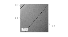
- 1 is an enlarged observation image of the vicinity of the surface of a cross section of a strengthened crystallized glass according to an embodiment of the present invention.
- 1 is an enlarged observation image of the vicinity of the surface of a cross section of a strengthened crystallized glass of a comparative example of the present invention.
- crystallizable glass glass that does not necessarily contain crystals (at least crystals are not intentionally precipitated) before crystallization treatment.
- glass containing crystals obtained by subjecting crystallizable glass to crystallization treatment is called crystallized glass.
- glass obtained by subjecting crystallized glass to ion exchange treatment is called reinforced crystallized glass.
- the crystallizable glass, crystallized glass, and strengthened crystallized glass of the present invention preferably contain, in mole percent, SiO 2 50-80%, Al 2 O 3 0-12%, P 2 O 5 0-15%, Li 2 O 1.5-30%, Na 2 O 0-15%, and ZrO 2 1.5-10%.
- the reasons for limiting the content of each component as described above are as follows. In the description of the content of each component, the percentage indicates mole percent unless otherwise specified.
- the numerical range indicated by "to” means a range including the numerical values before and after "to” as the minimum and maximum values, respectively.
- SiO 2 is a component that forms a glass network and is a component for precipitating crystals such as lithium disilicate and lithium metasilicate.
- the content of SiO 2 is preferably 50-80%, 55-75%, 60-73%, 60-70%, and particularly 65-70%. If the content of SiO 2 is too small, vitrification becomes difficult, the Young's modulus and weather resistance tend to decrease, and lithium disilicate and lithium metasilicate tend to precipitate. On the other hand, if the content of SiO 2 is too large, melting property and moldability tend to decrease, the thermal expansion coefficient becomes too low, making it difficult to match the thermal expansion coefficient of the surrounding material, and the transmittance tends to decrease due to the precipitation of heterogeneous crystals (unintended crystals).
- Al 2 O 3 is a component that adjusts the precipitation crystals and adjusts the compressive stress.
- the upper limit range of Al 2 O 3 is preferably 12% or less, 10% or less, 8% or less, 6% or less, 4.8% or less, 4.7% or less, 4.5% or less, 4.4% or less, 4.3% or less, 4.2% or less, 4.0% or less, 3.8% or less, 3.5% or less, 3.3% or less, 3.0% or less, 2.8% or less, 2.5% or less, 2.2% or less, 2.1% or less, and particularly 2.0% or less. If the content of Al 2 O 3 is too high, the compressive stress value of the strengthened crystallized glass may decrease.
- the lower limit range of the Al2O3 content is preferably 0% or more, 0.1% or more, 0.2% or more, 0.3% or more, 0.4% or more, 0.5% or more, 0.7% or more, 1.0% or more, particularly 1.5% or more.
- P2O5 is a component that promotes the phase separation of glass and helps the formation of crystal nuclei. However, if a large amount of P2O5 is introduced , the glass will be too phase separated and will tend to become cloudy. Therefore, the upper limit of the content of P2O5 is preferably 15% or less, 10% or less, 8% or less, 5% or less, particularly 3% or less, and the lower limit is preferably 0% or more, 0.2% or more, 0.3% or more, 0.4% or more, particularly 0.5% or more.
- Li 2 O is a component for precipitating crystals such as lithium disilicate and lithium metasilicate, and is also a component for enhancing ion exchange performance. However, if the content of Li 2 O is too high, the weather resistance is likely to decrease. Therefore, the upper limit range of Li 2 O is preferably 30% or less, 29% or less, 28% or less, 26% or less, particularly 25% or less, and the lower limit range is preferably 1.5% or more, 2% or more, 3% or more, 4% or more, 4.5% or more, 5% or more, 5.5% or more, 6% or more, 6.3% or more, 6.5% or more, 6.6% or more, 8% or more, 10% or more, 12% or more, 15% or more, 18% or more, 20% or more, 21% or more, 22% or more, 22.5% or more, 23% or more, 23.5% or more, 24% or more, particularly 24.5% or more.
- Na 2 O is a component that reduces high-temperature viscosity and significantly increases melting property. It is also a component that contributes to the initial melting of glass raw materials. However, if the content of Na 2 O is too high, the crystallite size tends to become coarse and the weather resistance tends to decrease.
- the upper limit range of Na 2 O is preferably 15% or less, 12% or less, 10% or less, 9.8% or less, 9.5% or less, 9.3% or less, 9.1% or less, 9% or less, 8.7% or less, particularly 7% or less, 6% or less, 5% or less, 4% or less, 3% or less, less than 2.4%, 2.2% or less, 2% or less, 1.8% or less, 1.5% or less, and when weather resistance is important, 1% or less, particularly less than 1%. In particular, 5% or less, 4% or less, and less than 3.8% are preferable in the crystallized glass before ion exchange.
- the lower limit range is preferably 0% or more, 0.1% or more, 0.3% or more, 0.5% or more, 0.8% or more, 1% or more, and particularly preferably 2% or more.
- ZrO2 is a component for generating crystal nuclei.
- the upper limit range of ZrO2 is preferably 10% or less, 9% or less, 8% or less, 7% or less, 6.5% or less, particularly 6% or less
- the lower limit range is preferably 1.5% or more, 1.7% or more, 1.9% or more, 2% or more, 2.1% or more, 2.3% or more, 2.5% or more, 2.7% or more, 3% or more, 3.3% or more, 3.5% or more, particularly 4% or more.
- the molar ratio Al 2 O 3 /SiO 2 is preferably 0.07 or less, 0.06 or less, 0.05 or less, 0.045 or less, 0.043 or less, 0.04 or less, 0.038 or less, 0.035 or less, 0.033 or less, 0.03 or less, 0.028 or less, particularly 0 to 0.025. If the molar ratio Al 2 O 3 /SiO 2 is too large, it may be difficult to vitrify or the compressive stress value of the strengthened crystallized glass may decrease. Note that "Al 2 O 3 /SiO 2 " is the value obtained by dividing the content of Al 2 O 3 by the content of SiO 2 .
- the molar ratio Al 2 O 3 /Li 2 O is preferably 0.2 or less, 0.15 or less, 0.14 or less, 0.13 or less, 0.12 or less, 0.11 or less, 0.1 or less, 0.09 or less, 0.08 or less, 0.07 or less, particularly 0 to 0.065. If the molar ratio Al 2 O 3 /Li 2 O is too large, crystals such as lithium disilicate and lithium metasilicate may be difficult to precipitate, crystals such as petalite may be easily precipitated, and the compressive stress value of the strengthened crystallized glass may be reduced. Note that "Al 2 O 3 /Li 2 O" is the value obtained by dividing the content of Al 2 O 3 by the content of Li 2 O.
- the molar ratio Al 2 O 3 /(SiO 2 +Li 2 O) is preferably 0.06 or less, 0.055 or less, 0.05 or less, 0.047 or less, 0.045 or less, 0.043 or less, 0.04 or less, 0.038 or less, 0.035 or less, 0.033 or less, particularly 0 to 0.03. If the molar ratio Al 2 O 3 /(SiO 2 +Li 2 O) is too large, crystals such as lithium disilicate and lithium metasilicate may be difficult to precipitate, crystals such as petalite may be easily precipitated, and the compressive stress value of the strengthened crystallized glass may be reduced. Note that "Al 2 O 3 /(SiO 2 +Li 2 O)" is the value obtained by dividing the content of Al 2 O 3 by the total amount of SiO 2 and Li 2 O.
- K 2 O is a component that enhances ion exchange performance, reduces high-temperature viscosity, and enhances melting property. However, if the content of K 2 O is too high, the crystallite size tends to become coarse. Therefore, the content of K 2 O is preferably 0 to 7%, 0 to 5%, 0 to 3%, 0 to 2%, 0 to 1.5%, 0 to 1.2%, 0 to less than 0 to 1%, and particularly 0 to 0.8%.
- the total amount of Na 2 O and K 2 O, Na 2 O + K 2 O, in the crystallizable glass before crystallization is preferably 0 to 8%, 0 to 7%, 0 to 5%, 0 to less than 3.8%, 0 to 3.5%, 0 to 3%, 0 to 2.5%, particularly preferably 0 to 2%. If the content of Na 2 O + K 2 O is too high, the crystallite size tends to become coarse.
- the molar ratio (Na 2 O+K 2 O)/(Li 2 O+Na 2 O+K 2 O) is preferably less than 1.50, 1.40 or less, 1.30 or less, 1.20 or less, 1.10 or less, 1.00 or less, 0.05 to 0.90, particularly 0.10 to 0.80. If the molar ratio (Na 2 O+K 2 O)/(Li 2 O+Na 2 O+K 2 O) is too large, the ion exchange performance of the NaNO 3 molten salt decreases, and it becomes difficult to form a portion in the strengthened crystallized glass where the Na ion concentration decreases from the surface side of the glass toward the inside, that is, a compressive stress layer based on Na ions.
- ( Na2O + K2O )/( Li2O + Na2O + K2O ) is a value obtained by dividing the total amount of Na2O and K2O by the total amount of Li2O , Na2O and K2O .
- B 2 O 3 is a component that enhances melting property and devitrification resistance. However, if the content of B 2 O 3 is too high, the weather resistance is likely to decrease. Therefore, the content of B 2 O 3 is preferably 0 to 10%, 0 to 7%, 0 to 5%, 0 to 3%, and particularly preferably 0 to less than 1%.
- MgO is a component that increases Young's modulus and ion exchange performance, as well as lowering high-temperature viscosity and improving meltability.
- the MgO content is preferably 0-10%, 0-7%, 0-4%, 0-2%, 0-1%, and especially 0-0.1%.
- CaO is a component that reduces high-temperature viscosity and improves melting properties.
- it is a component that reduces batch costs because the raw material is relatively inexpensive to introduce.
- the CaO content is preferably 0-5%, 0-3%, 0-1%, and especially 0-0.5%.
- SrO is a component that suppresses phase separation and also suppresses coarsening of crystallite size, but if the content is too high, it becomes difficult to precipitate crystals by heat treatment. Therefore, the SrO content is preferably 0-5%, 0-3%, 0-2%, and especially 0-1%.
- BaO is a component that suppresses coarsening of crystallite size, but if its content is too high, it becomes difficult to precipitate crystals by heat treatment. Therefore, the BaO content is preferably 0-5%, 0-3%, 0-2%, and especially 0-1%.
- ZnO is a component that reduces high-temperature viscosity and significantly increases meltability, as well as suppresses coarsening of crystallite size. However, if the ZnO content is too high, the glass becomes more susceptible to devitrification during molding. Therefore, the ZnO content is preferably 0-5%, 0-3%, 0-2%, and especially 0-1%.
- TiO2 is a component for generating crystal nuclei and improving weather resistance. However, if a large amount of TiO2 is introduced, the glass becomes colored and the transmittance tends to decrease. Therefore, the content of TiO2 is preferably 0 to 5%, 0 to 3%, and particularly 0 to less than 1%.
- SnO2 is a component that enhances ion exchange performance, but if its content is too high, devitrification resistance is likely to decrease. Therefore, the content of SnO2 is preferably 0 to 3%, 0.01 to 3%, 0.05 to 3%, 0.1 to 3%, particularly 0.2 to 3%.
- an effective fining agent can be added.
- the fining agent one or more selected from the group consisting of Cl, SO 3 , CeO 2 , and Sb 2 O 3 (preferably Cl and SO 3 ) may be added in an amount of 0.001 to 1%.
- the preferred content of Fe2O3 is less than 1000 ppm (less than 0.1%), less than 800 ppm, less than 600 ppm, less than 400 ppm, and particularly less than 300 ppm. Furthermore, it is preferable to regulate the content of Fe2O3 within the above range and the molar ratio SnO2 /( Fe2O3 + SnO2 ) to 0.8 or more, 0.9 or more, and particularly 0.95 or more. In this way, the total light transmittance at wavelengths of 400 to 770 nm is easily improved.
- Y 2 O 3 is a component that increases the strength of glass.
- the cost of the raw material itself is high, and if added in a large amount, the devitrification resistance is likely to decrease. Therefore, the content of Y 2 O 3 is preferably 0 to 15%, 0 to 12%, 0 to 10%, and particularly preferably 0.1 to 1%.
- Gd 2 O 3 , Nb 2 O 5 , La 2 O 3 , Ta 2 O 5 , and HfO 2 are components that increase the strength of glass.
- the raw materials of Gd 2 O 3 , Nb 2 O 5 , La 2 O 3 , Ta 2 O 5 , and HfO 2 are expensive, and when added in large amounts, the devitrification resistance is likely to decrease.
- the total and individual contents of Gd 2 O 3 , Nb 2 O 5 , La 2 O 3 , Ta 2 O 5 , and HfO 2 are preferably 0 to 15%, 0 to 10%, 0 to 5%, and particularly 0 to 3%.
- the strengthened crystallized glass of the present invention preferably does not substantially contain As 2 O 3 , PbO, F, etc., as a composition. Also, from an environmental perspective, it is preferable that the strengthened crystallized glass of the present invention does not substantially contain Bi 2 O 3.
- the phrase "substantially does not contain " means that the specified components are not actively added as glass components, but the addition of impurity levels is permitted, and specifically refers to the case where the content of the specified components is less than 0.05%.
- the preferred content ranges of each component can be appropriately combined to obtain a preferred composition range.
- the following composition ranges (1) to (3) are preferred because they can achieve high levels of strength, transmittance, and impact resistance.
- (1) Contains, in mole percent, 50-80% SiO 2 , 0-12% Al 2 O 3 , 0-15% P 2 O 5 , 1.5-30% Li 2 O , 0-less than 3.8% Na 2 O + K 2 O , 0-less than 3.8% Na 2 O , 0-less than 3.8% K 2 O , and 1.5-10% ZrO 2 .
- composition in mole percent, is 50-80% SiO 2 , 0-12% Al 2 O 3 , 0-15% P 2 O 5 , 1.5-30% Li 2 O , 0-less than 3.8% Na 2 O + K 2 O , 0-less than 3.8% Na 2 O , 0-less than 3.8% K 2 O , and 1.5-10% ZrO 2 , with a molar ratio of (Na 2 O + K 2 O) / (Li 2 O + Na 2 O + K 2 O) being 1.20 or less.
- the crystallized glass and reinforced crystallized glass of the present invention preferably have the following properties:
- any of lithium disilicate, lithium metasilicate, ⁇ -quartz, ⁇ -spodumene, trilithium phosphate, and petalite is precipitated, and it is particularly preferable that any of lithium disilicate, lithium metasilicate, and trilithium phosphate is precipitated. It is also preferable that lithium disilicate or lithium metasilicate is precipitated as the main crystal (the crystal with the largest amount of precipitation).
- the full width at half maximum (FWHM) of the maximum peak of the X-ray diffraction spectrum is preferably 0.120° or more, 0.121° or more, 0.122° or more, 0.123° or more, 0.125° or more, 0.130° or more, 0.135° or more, 0.140° or more, and particularly preferably 0.150° or more. If the full width at half maximum (FWHM) of the maximum peak of the X-ray diffraction spectrum is too small, the transmittance is likely to decrease.
- the fracture toughness K 1C of the crystallized glass before the ion exchange treatment is preferably 0.7 MPa ⁇ m 0.5 or more, 0.8 MPa ⁇ m 0.5 or more, 1.0 MPa ⁇ m 0.5 or more, 1.2 MPa ⁇ m 0.5 or more, particularly 1.5 to 3.5 MPa ⁇ m 0.5 . If the fracture toughness K 1C is too small, the strength is likely to be low.
- the "fracture toughness K 1C" is measured using a pre-crack introduction fracture test method (SEPB method: Single-Edge-Precracked-Beam method) based on JIS R1607 "Fracture toughness test method for fine ceramics".
- the SEPB method is a method in which the maximum load until a test piece breaks is measured by a three-point bending fracture test of a precracked test piece, and the plane strain fracture toughness K1C is calculated from the maximum load, the precrack length, the test piece dimensions, and the distance between bending supports.
- the measured value of the fracture toughness K1C of each glass is the average value of five measurements.
- the Young's modulus of the crystallized glass before the ion exchange treatment is preferably 70 GPa or more, 72 GPa or more, 73 GPa or more, 74 GPa or more, 75 GPa or more, 76 GPa or more, 77 GPa or more, 78 GPa or more, 79 GPa or more, 80 GPa or more, 83 GPa or more, 85 GPa or more, 87 GPa or more, 90 GPa or more, and particularly 100 to 150 GPa. If the Young's modulus is low, the crystallized glass will be easily bent if the plate thickness is thin. The "Young's modulus" can be measured by the well-known resonance method.
- the Vickers hardness of the crystallized glass before the ion exchange treatment is preferably 500 or more, 550 or more, 580 or more, and particularly 600 to 2500. If the Vickers hardness is too low, it will be easily scratched.
- the "Vickers hardness” is a value measured by pressing a Vickers indenter with a load of 100 gf using a Vickers hardness tester.
- the transmittance of the crystallized glass in the thickness direction at a wavelength of 550 nm is preferably 75% or more, 76% or more, 77% or more, 78% or more, 79% or more, 81% or more, 83% or more, 85% or more, 88% or more, and particularly 89% or more.
- the "transmittance" at a specific wavelength is measured using a spectrophotometer (V-670 manufactured by JASCO Corporation) to measure the transmittance at that wavelength in the thickness direction.
- the strengthened crystallized glass of the present invention preferably has the following properties:
- the average reflectance of the reinforced crystallized glass of the present invention at wavelengths of 360 to 780 nm is 9.5% or less.
- the average reflectance of the reinforced crystallized glass at wavelengths of 360 to 780 nm is more preferably 9.4% or less, 9.3% or less, 9.2% or less, 9.1% or less, 9.0% or less, 8.9% or less, 8.8% or less, 8.7% or less, 8.6% or less, 8.5% or less, 8.4% or less, 8.3% or less, 8.2% or less, or 8.1% or less.
- the average reflectance in the wavelength range i.e., the reflectance in the visible light wavelength range
- the reinforced crystallized glass is used as a cover glass for a display device, it is likely to reflect external light, and the visibility of the display is likely to decrease.
- the average reflectance in the wavelength range is preferably 3% or more, more preferably 3.5% or more.
- the average reflectance for wavelengths between 360 and 780 nm can be determined by measurement and calculation using a spectrophotometer. The average reflectance can also be measured and calculated based on JIS R 3106.
- the transmittance of the reinforced crystallized glass in the thickness direction at a wavelength of 550 nm is preferably 75% or more, 76% or more, 77% or more, 78% or more, 79% or more, 81% or more, 83% or more, 85% or more, 88% or more, and particularly 89% or more.
- the strengthened crystallized glass of the present invention preferably has a portion where the Na ion concentration decreases from the surface side of the glass to the inside side, in other words, a portion where the Na ion concentration increases from the inside side of the glass to the surface side. This increases the resistance to crack penetration from the glass surface, and the impact resistance is likely to be high.
- an ion exchange process is performed to introduce Na ions into the glass using NaNO 3 molten salt, the Na ion concentration at the glass surface becomes relatively high, and it is possible to form a portion where the Na ion concentration decreases from the surface side of the glass to the inside side.
- the strengthened crystallized glass has a portion where the Li ion concentration increases from the surface side of the glass to the inside side, that is, a portion where the Li ion concentration decreases from the inside side of the glass to the surface side.
- the "Na ion concentration" can be confirmed by, for example, measuring the cross section of the sample with SEM-EDX. In this way, a strengthened crystallized glass having high transmittance and high impact resistance can be obtained.
- Figure 1 is a schematic diagram of the cross-sectional structure of the strengthened crystallized glass 1 of the present invention.
- the strengthened crystallized glass 1 has a compressive stress layer 11 formed by ion exchange on the surface, and a tensile stress layer 12 at the center in the thickness direction from the compressive stress layer 11.
- the maximum compressive stress value (CS) of the compressive stress layer 11 is preferably 200 MPa or more, 250 MPa or more, 300 MPa or more, 400 MPa or more, 500 MPa or more, 520 MPa or more, 530 MPa or more, and particularly 550 MPa or more. If the compressive stress value is low, the resistance to crack penetration is low and impact resistance is likely to be low. However, if the compressive stress value is too high, the tensile stress value in the center becomes excessive, which is dangerous as it will cause many fragments when broken. Therefore, the compressive stress value is preferably 1500 MPa or less, 1400 MPa or less, 1300 MPa or less, or 1200 MPa or less.
- the stress depth (DOC) of the compressive stress layer 11 is preferably 50 ⁇ m or more, 60 ⁇ m or more, 70 ⁇ m or more, 80 ⁇ m or more, 85 ⁇ m or more, 90 ⁇ m or more, 95 ⁇ m or more, or 100 ⁇ m or more.
- the stress depth of the compressive stress layer is preferably 13% or more, 14% or more, 15% or more, 16% or more, 17% or more, 17.5% or more, 18% or more, 18.5% or more, and particularly 19% or more of the plate thickness. If the stress depth is small, the resistance to crack penetration is small and impact resistance is likely to be low.
- the maximum tensile stress value of the internal tensile stress layer 12 is preferably 180 MPa or less, 150 PMa or less, 120 MPa or less, and particularly 110 MPa or less. If the internal tensile stress value is too high, the strengthened crystallized glass is prone to self-destruction due to hard scratches. On the other hand, if the internal tensile stress value is too low, it becomes difficult to ensure the strength of the strengthened crystallized glass.
- the internal tensile stress value is preferably 35 MPa or more, 45 MPa or more, 55 MPa or more, and particularly 70 MPa or more.
- the internal tensile stress value can be measured, for example, using a scattered light photoelastic stress meter SLP-2000 from Orihara Seisakusho.
- the P180 scratch strength is an index of impact resistance, and is preferably 250 MPa or more, 270 MPa or more, 290 MPa or more, and particularly 300 MPa or more. There is no particular upper limit to the P180 scratch strength, but in reality it is 800 MPa or less.
- the P180 scratch strength can be measured by the method described below.
- the strengthened crystallized glass of the present invention is preferably in a plate shape, and the plate thickness is preferably 2.0 mm or less, 1.5 mm or less, 1.3 mm or less, 1.1 mm or less, 1.0 mm or less, and particularly 0.9 mm or less.
- the plate thickness is preferably 0.3 mm or more, 0.4 mm or more, 0.5 mm or more, 0.6 mm or more, and particularly 0.7 mm or more.
- the strengthened crystallized glass 1 of the present invention has a low crystallization layer 21 on the surface, and a central layer 22 on the inner side (center side) of the low crystallization layer 21 in the thickness direction of the glass.
- amorphous and crystalline materials are mixed.
- the low crystallinity layer 21 is a surface layer having a lower degree of crystallinity than the central layer 22.
- the depth of the low crystallinity layer 21 is more preferably 0.05 ⁇ m or more, 0.1 ⁇ m or more, 0.2 ⁇ m or more, 0.3 ⁇ m or more, 0.5 ⁇ m or more, 0.8 ⁇ m or more, 1.0 ⁇ m or more, 1.5 ⁇ m or more, or 2.0 ⁇ m or more.
- the depth of the low crystallinity layer 21 is preferably 150 ⁇ m or less, 120 ⁇ m or less, 100 ⁇ m or less, 90 ⁇ m or less, 80 ⁇ m or less, 70 ⁇ m or less, 60 ⁇ m or less, 50 ⁇ m or less, 45 ⁇ m or less, 40 ⁇ m or less, 35 ⁇ m or less, or 30 ⁇ m or less.
- the depth of the low crystallinity layer 21 can be confirmed from a transmission electron microscope (TEM) image or an electron diffraction pattern of a cross section of the strengthened crystallized glass.
- the low crystallinity layer 21 is preferably formed by modifying the surface of glass of the same quality as the amorphous part of the central layer 22, rather than by subsequent film formation.
- the components of the low crystallinity layer 21 preferably have the same components as the central layer 22. More preferably, it contains SiO 2 , Al 2 O 3 , Li 2 O, Na 2 O, P 2 O 5 , and ZrO 2 .
- the components of the surface layer can be measured by energy dispersive X-ray spectroscopy (EDX) or the like. More specifically, it is preferable that the glass composition of the amorphous part contained in the low crystallinity layer 21 and the glass composition of the amorphous part contained in the central layer 22 are substantially the same glass composition.
- the crystals contained in the low crystallinity layer 21 and the crystals contained in the central layer 22 are substantially the same type of crystals. According to such a configuration, the low crystallinity layer 21 can be formed integrally with the central layer 22 by a modification process, so that the risk of delamination can be reduced compared to the case where the optical film layer is formed afterwards.
- the low crystallinity layer 21 of the reinforced crystallized glass 1 of the present invention may be a layer in which amorphous and crystalline materials are mixed.
- the crystallinity of the low crystallinity layer 21 is preferably 60% or less. More preferably, it is 58% or less, 55% or less, 53% or less, 50% or less, 48% or less, 45% or less, 43% or less, 40% or less, 35% or less, 30% or less, 25% or less, 20% or less, 15% or less, or 10% or less.
- the crystallinity of the low crystallinity layer 21 of the reinforced crystallized glass 1 of the present invention is preferably 1% or more, 2% or more, 5% or more, 10% or more, 15% or more, 20% or more, or 30% or more.
- productivity can be improved.
- the crystallinity of the low crystallinity layer 21 may be 0%.
- the crystallinity of the low crystal layer 21 can be measured by in-plane measurement using an X-ray diffraction device.
- the degree of crystallization in the central layer 22 of the reinforced crystallized glass 1 of the present invention is preferably 3% or more, 5% or more, 10% or more, 13% or more, 15% or more, 20% or more, 25% or more, 30% or more, 35% or more, 40% or more, 45% or more, or 50% or more.
- the difference between the degree of crystallization in the central layer 22 of the reinforced crystallized glass 1 of the present invention and the degree of crystallization in the low crystallization layer 21 is preferably 1% or more, 2% or more, 3% or more, 5% or more, 10% or more, 15% or more, 20% or more, 30% or more, 40% or more, or 50% or more.
- the technical concepts of the low crystallinity layer 21 and the central layer 22 and the technical concepts of the compressive stress layer 11 and the tensile stress layer 12 are independent of each other, and these concepts can coexist in each region in the depth direction of the strengthened crystallized glass 1.
- the region shown by diagonal hatching in FIG. 1 is the low crystallinity layer 21 and also part of the compressive stress layer 11.
- the region shown by dot hatching in FIG. 1 is the central layer 22 and also part of the compressive stress layer 11.
- the non-hatched region in FIG. 1 is the central layer 22 and also the tensile stress layer 12.
- the strengthened crystallized glass of the present invention may be configured such that the depth of the compressive stress layer 11 is less than the depth of the low crystallinity layer 21.
- the depth of the compressive stress layer 11 can be changed by adjusting the ion exchange treatment time, etc.
- the method for producing the strengthened crystallized glass of the present invention includes a step of preparing the crystallized glass and a step of chemically strengthening the crystallized glass by an ion exchange treatment.
- any method may be used as long as crystallized glass having the above characteristics is available.
- it can be prepared according to the following procedure.
- Glass raw materials prepared to obtain a glass composition within the above-mentioned composition range are fed into a continuous melting furnace, heated and melted at 1200-1700°C, and clarified.
- the molten glass is then fed into a molding device, formed into a plate shape, and cooled to obtain crystalline glass. After forming into a plate shape, the glass can be cut to the specified dimensions using a well-known method.
- the method for forming the molten glass into a sheet shape can be any method, such as the overflow downdraw method, the float method, the slot downdraw method, the redraw method, the roll-out method, the press method, etc.
- the heat treatment step preferably includes a phase separation forming step for generating phase separation in the glass matrix, a crystal nucleus generating step for generating crystal nuclei, and a crystal growth step for growing the generated crystal nuclei.
- the heat treatment temperature in the phase separation forming step is 400 to 600°C, particularly preferably 480 to 580°C, and the heat treatment time is 10 minutes to 24 hours, particularly preferably 30 minutes to 12 hours.
- the heat treatment temperature in the crystal nucleus generating step is 500 to 700°C, particularly preferably 520 to 650°C, and the heat treatment time is 10 minutes to 24 hours, particularly preferably 30 minutes to 12 hours.
- the heat treatment temperature in the crystal growth step is also preferably 690 to 920°C, particularly preferably 700 to 830°C, and the heat treatment time is 10 minutes to 5 hours, particularly preferably 30 minutes to 3 hours.
- the heating rate is preferably 1° C./min to 30° C./min, particularly preferably 1° C./min to 10° C./min. If the heat treatment temperature, heat treatment time and heating rate are outside the above ranges, the crystallite size becomes coarse and the crystallinity decreases.
- ⁇ Ion exchange treatment> The crystallized glass plate prepared as described above is subjected to an ion exchange treatment to obtain a strengthened crystallized glass having a compressive stress layer on the surface due to ion exchange. By performing the ion exchange treatment, a compressive stress layer is formed on the surface, so that the strength can be increased.
- an ion exchange process is carried out using an ion exchange mixture.
- the ion exchange mixture is a processing agent that undergoes ion exchange with the components in the crystallized glass by coming into contact with the crystallized glass.
- the ion exchange mixture contains a molten salt and an additive.
- the molten salt is a salt containing a component that can be ion-exchanged with the component in the crystallized glass, and is typically an alkali nitrate.
- the alkali nitrate preferably contains at least NaNO 3.
- Other examples of the alkali nitrate include KNO 3 and LiNO 3 , which can be mixed with NaNO 3 for use.
- the molten salt preferably contains, in mass %, 50-100% NaNO 3 and 0-50% KNO 3 + LiNO 3 . In this embodiment, the case where NaNO 3 (100%) is used is illustrated.
- the additive is silicic acid or a silicate, typically an alkali metal silicate.
- silicic acid or a silicate particularly an alkali metal silicate, it is possible to suppress the reflectance of the reinforced crystallized glass before and after ion exchange.
- the additive is preferably sodium silicate.
- the alkali metal silicate preferably contains at least one selected from Na 2 SiO 3 , Na 4 SiO 4 , Na 2 Si 2 O 5 , and Na 2 Si 4 O 9.
- the sodium silicate is preferably an anhydride, but may be a hydrate.
- the silicic acid or silicate as an additive is preferably a crystalline substance. Furthermore, the silicic acid or silicate is preferably a powdered silicic acid or silicate crystalline substance.
- the silicic acid or silicate crystalline substance is preferably in a powdered form when added to the molten salt, but may be in a powdered form by grinding in the molten salt after addition to the molten salt.
- the average particle size D50 of the powder is preferably 10 to 1000 ⁇ m.
- the average particle size D50 of the powder is more preferably 900 ⁇ m or less, 800 ⁇ m or less, 700 ⁇ m or less, 500 ⁇ m or less, or 450 ⁇ m or less. In order to prevent dust before addition, the average particle size D50 of the powder is more preferably 20 ⁇ m or more, 50 ⁇ m or more, 100 ⁇ m or more, 150 ⁇ m or more, 200 ⁇ m or more, or 250 ⁇ m or more.
- the amount of additive to be added to the molten salt i.e., the amount of silicic acid or silicate
- the amount of silicic acid or silicate added is more preferably 1 to 30 parts by mass, 2 to 25 parts by mass, 3 to 20 parts by mass, or 4 to 15 parts by mass. If the amount of additive added is too small, the reflectance suppression effect and sufficient ion adjustment effect will not be obtained, and if the amount added is too large, there is a concern that the cost of the additive will increase.
- the additive is preferably an alkali metal silicate.
- the alkali metal silicate as an additive is preferably a metal salt that contains an alkali metal component that is ion-exchangeable with the alkali metal component that dissolves from the crystallized glass into the molten salt during ion exchange processing, and contains a monovalent metal component different from the dissolve ion.
- the alkali metal component that dissolves into the molten salt is Li ions
- using sodium silicate as the additive can ion-exchange the Li ions dissolved in the molten salt with the Na ions contained in the alkali metal silicate, thereby suppressing an increase in the concentration of Li ions in the molten salt.
- the conditions for the ion exchange treatment such as the temperature of the molten salt and the immersion time, may be determined as desired, but the temperature of the molten salt is, for example, 350°C to 500°C, preferably 360°C to 480°C, 370°C to 450°C, or 380°C to 440°C.
- the immersion time is, for example, 0.1 to 30 hours, preferably 0.2 to 20 hours, 0.3 to 15 hours, 0.5 to 10 hours, 1 to 9 hours, 2 to 9 hours, and particularly 3.5 to 8 hours.
- Reinforced crystallized glass is obtained by immersing part or all of the crystallized glass in the above-mentioned ion exchange mixture and performing ion exchange processing.
- This type of processing makes part of the surface layer of the crystallized glass before the ion exchange processing amorphous, creating a low crystal layer 21, and by lowering the refractive index, it is possible to lower the average reflectance of the reinforced crystallized glass after the ion exchange processing at wavelengths of 360 to 780 nm.
- the effect of improving scratch resistance and crack resistance by improving the plasticity of the surface and improving ion exchange performance by reducing the density can be obtained.
- the additives After the additives are added to the molten salt, it is preferable to stir the molten salt. Stirring can be done manually with a stick or paddle, or automatically by machine. After stirring, the additives can be dispersed in the molten salt before the next lot of ion exchange treatment is performed, or the additives can be left to settle on the inner bottom of the tank containing the molten salt.
- glass raw materials were mixed to obtain the glass compositions shown in Tables 1 to 3, and melted at 1500°C for 8 hours using a platinum pot.
- the resulting molten glass was then poured onto a carbon plate and formed into a flat plate to obtain a glass plate.
- the surface of the resulting glass plate was optically polished to a plate thickness of 1000 ⁇ m (1.0 mm) or 600 ⁇ m (0.6 mm).
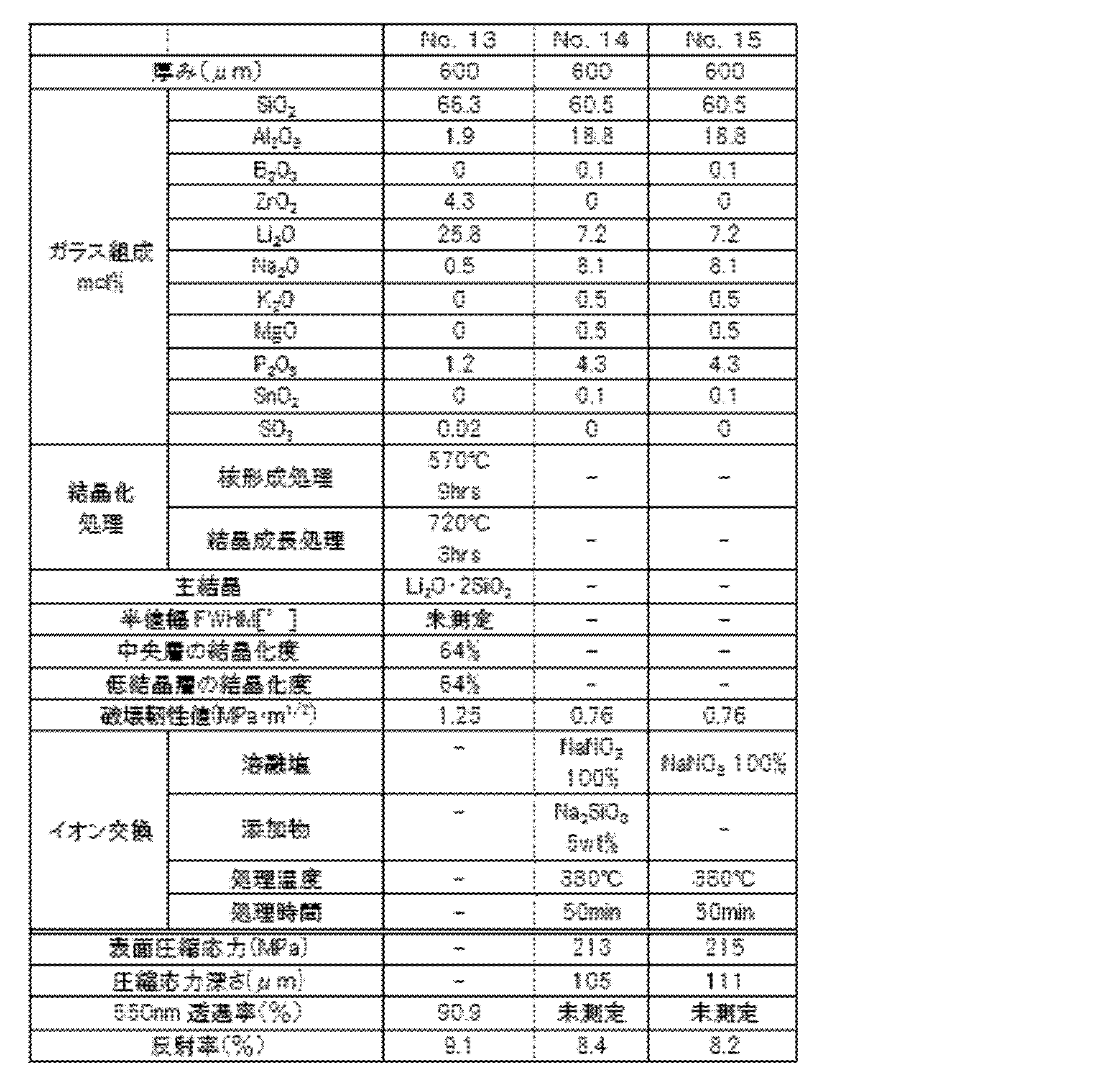
- the obtained glass samples No. 1 to 13 were heat-treated in an electric furnace under the heat treatment conditions shown in Tables 1 to 3 to precipitate and grow crystals in the glass matrix. They were then cooled to room temperature to obtain crystallized glass plates. No special heat treatment was performed on the non-crystalline glass plates (samples No. 14 and 15). The obtained glass plates were evaluated for the following properties.
- the crystallinity of the central layer was calculated from the ratio of the area excluding the background from the obtained X-ray diffraction spectrum to the area excluding the amorphous part (halo peak).
- the full width at half maximum (FWHM) was derived by peak fitting at the peak with the maximum intensity excluding the background and amorphous part (halo peak).
- samples No. 1, 2, 4, 5, 7, 8, 10, 11, 12, 14, and 15 were subjected to ion exchange treatment under the conditions shown in Tables 1 to 3 to form a compressive stress layer on the surface, thereby obtaining reinforced crystallized glass (No. 1, 2, 4, 5, 7, 8, 10, 11, and 12) and reinforced amorphous glass (No. 14 and 15).
- Samples No. 1, 4, 7, 10, 11, and 14 were subjected to ion exchange treatment using an ion exchange mixture containing silicic acid or an alkali metal silicate as an additive.
- samples No. 2, 5, 8, 12, and 15 were subjected to ion exchange treatment using a molten salt that did not contain an additive.
- the amount of additives shown in Tables 1 to 3 is the amount of alkali metal silicate added in parts by mass when the molten salt is taken as 100 parts by mass.
- the surface compressive stress value and compressive stress depth were measured using an Orihara Manufacturing Co., Ltd. scattered light photoelastic stress meter SLP-2000.
- the photoelastic constant of No. 1, 2, 4, 5, 7, 8, 10, 11, and 12 was set to 27.0 and the refractive index was set to 1.55, and the photoelastic constant of No. 14 and 15 was set to 30.5 and the refractive index was set to 1.51.
- the 550 nm transmittance is the value measured at a wavelength of 550 nm in the thickness direction of the glass using a spectrophotometer (V-670 manufactured by JASCO Corporation).
- Reflectance was measured and calculated as the average reflectance for wavelengths from 360 to 780 nm. Reflectance at each wavelength was measured using a spectrophotometer (using an integrating sphere, manufactured by JASCO Corporation, Model V-670).
- Figure 2 shows the measurement results of reflectance at each wavelength for samples No. 1 to 3. In Figure 2, the horizontal axis indicates wavelength, and the vertical axis indicates reflectance at each wavelength.
- the degree of crystallinity of the low crystallinity layer was evaluated by in-plane measurement using a parallel beam method with an X-ray diffraction device (SmarLab, manufactured by Rigaku).
- sample No. 1 which is an embodiment, is a reinforced crystallized glass, and therefore has a higher fracture toughness value and better impact resistance than comparative samples Nos. 14 and 15.
- sample No. 1 uses an ion exchange mixture containing sodium metasilicate as an additive in the ion exchange treatment, and thus the reflectance is suitably suppressed compared to comparative samples Nos. 2 and 3.
- Sample No. 1, which is an embodiment, corresponds to the reinforced crystallized glass of comparative sample No. 3 after ion exchange treatment, and its average reflectance at wavelengths of 360 to 780 nm is lower than that before ion exchange treatment.
- Sample No. 12 which is a comparative example, was composed of relatively homogeneous crystallized glass with a high degree of crystallization filled with black dot crystals from the glass surface 1a to the inside of the glass.
- sample No. 12 which is a comparative example, was composed of relatively homogeneous crystallized glass with a high degree of crystallization filled with black dot crystals from the glass surface 1a to the inside of the glass.
- sample No. 10 an ion exchange mixture containing sodium metasilicate was used as an additive in the ion exchange process, which resulted in the formation of a low crystallinity layer on the surface, lowering the refractive index of the surface and effectively suppressing the reflectance.
- the principle by which this low crystallinity layer was formed is unclear, but when a similar sample was measured using energy dispersive X-ray spectroscopy (EDX), ions such as Si, Al, P, Zr, and Na were detected, suggesting that the ion exchange process changed part of the crystalline glass to amorphous.
- EDX energy dispersive X-ray spectroscopy
Landscapes
- Chemical & Material Sciences (AREA)
- Engineering & Computer Science (AREA)
- Materials Engineering (AREA)
- Life Sciences & Earth Sciences (AREA)
- Chemical Kinetics & Catalysis (AREA)
- General Chemical & Material Sciences (AREA)
- Geochemistry & Mineralogy (AREA)
- Organic Chemistry (AREA)
- Crystallography & Structural Chemistry (AREA)
- Dispersion Chemistry (AREA)
- Ceramic Engineering (AREA)
- Glass Compositions (AREA)
- Surface Treatment Of Glass (AREA)
Abstract
Description
前記イオン交換用混合物は、溶融塩と、添加物としてアルカリ金属珪酸塩と、を含み、
前記イオン交換処理前の前記結晶化ガラスの波長360~780nmにおける平均反射率より、前記イオン交換処理後の前記強化結晶化ガラスの波長360~780nmにおける平均反射率を低下させる、ことを特徴とする。
(1)モル%で、SiO2 50~80%、Al2O3 0~12%、P2O5 0~15%、Li2O 1.5~30%、Na2O+K2O 0~3.8%未満、Na2O 0~3.8%未満、K2O 0~3.8%未満、ZrO2 1.5~10%を含有。
(2)モル%で、SiO2 50~80%、Al2O3 0~12%、P2O5 0~15%、Li2O 1.5~30%、Na2O+K2O 0~3.5%、Na2O 0~2%、K2O 0~1.2%、ZrO2 1.5~10%を含有。
(3)モル%で、SiO2 50~80%、Al2O3 0~12%、P2O5 0~15%、Li2O 1.5~30%、Na2O+K2O 0~3.8%未満、Na2O 0~3.8%未満、K2O 0~3.8%未満、ZrO2 1.5~10%を含有し、モル比(Na2O+K2O)/(Li2O+Na2O+K2O)が1.20以下である。
本発明の強化結晶化ガラスの製造方法について説明する。本発明の強化結晶化ガラスの製造方法は、結晶化ガラスを準備する工程と、結晶化ガラスをイオン交換処理により化学強化する工程とを備える。
次に、結晶性ガラスを熱処理することにより結晶化ガラス板を得る。熱処理工程は、ガラスマトリクス中に分相を生じさせる分相形成工程と、結晶核を生成する結晶核生成工程と、生成した結晶核を成長させる結晶成長工程と、を有することが好ましい。分相形成工程の熱処理温度は400~600℃、特に480~580℃が好ましく、熱処理時間は10分間~24時間、特に30分~12時間が好ましい。結晶核生成工程の熱処理温度は500~700℃、特に520~650℃が好ましく、熱処理時間は10分間~24時間、特に30分~12時間が好ましい。温度を適切に調整することによって、上記の分相形成工程と結晶核生成工程を同時に行ってもよい。また結晶成長工程の熱処理温度は690~920℃、特に700~830℃が好ましく、熱処理時間は10分間~5時間、特に30分間~3時間が好ましい。また昇温速度は1℃/分~30℃/分、特に1℃/分~10℃/分が好ましい。熱処理温度、熱処理時間及び昇温速度が上記範囲外になると、結晶子サイズが粗大化したり、結晶化度が低下したりする。
上記のようにして準備された結晶化ガラス板をイオン交換処理して、表面にイオン交換による圧縮応力層を有する強化結晶化ガラスを得る。イオン交換処理を行うと、表面に圧縮応力層が形成されるため、強度を高めることができる。


11 圧縮応力層
12 引張応力層
21 低結晶層
22 中央層
Claims (22)
- アルカリ金属成分を含む結晶化ガラスの一部または全部を、イオン交換用混合物に浸漬させてイオン交換処理することにより強化結晶化ガラスを得る、強化結晶化ガラスの製造方法であって、
前記イオン交換用混合物は、溶融塩と、添加物として珪酸または珪酸塩と、を含み、
前記イオン交換処理前の前記結晶化ガラスの波長360~780nmにおける平均反射率より、前記イオン交換処理後の前記強化結晶化ガラスの波長360~780nmにおける平均反射率を低下させる、ことを特徴とする強化結晶化ガラスの製造方法。 - 前記溶融塩は、NaNO3を含み、
前記添加物は、アルカリ金属珪酸塩であり、
前記アルカリ金属珪酸塩は、Na2SiO3、Na4SiO4、Na2Si2O5、およびNa2Si4O9から選ばれた少なくとも1種類以上を含む、請求項1に記載の強化結晶化ガラスの製造方法。 - 前記溶融塩は、組成として質量%で、NaNO3 50~100%、KNO3+LiNO3 0~50%含み、
前記イオン交換処理において、波長360~780nmにおける平均反射率を低下させるとともに、前記結晶化ガラスに圧縮応力層を形成する、
請求項2に記載の強化結晶化ガラスの製造方法。 - 前記溶融塩を100質量部とした場合に、前記添加物の添加量は0.1~30質量部である、請求項1又は2に記載の強化結晶化ガラスの製造方法。
- 前記結晶化ガラスが、組成として、モル%で、SiO2 50~80%、Al2O3 0~12%、P2O5 0~15%、Li2O 1.5~30%、Na2O 0~15%、ZrO2 1.5~10%を含有する、請求項1又は2に記載の強化結晶化ガラスの製造方法。
- リチウムダイシリケート及びリチウムメタシリケートの少なくとも一方が析出している、請求項1又は2に記載の強化結晶化ガラスの製造方法。
- 前記結晶化ガラスの表面の結晶化度を低下させて低結晶層を形成する工程をさらに備え、
前記低結晶層の結晶化度が、当該低結晶層よりガラスの厚さ方向中央に位置する中央層の結晶化度より小さい、請求項1又は2に記載の強化結晶化ガラスの製造方法。 - 前記イオン交換処理において、前記結晶化ガラスに圧縮応力層を形成するとともに前記低結晶層を形成する、請求項7に記載の強化結晶化ガラスの製造方法。
- 表面に圧縮応力層を有する強化結晶化ガラスであって、
波長360~780nmの平均反射率が9.5%以下である、強化結晶化ガラス。 - 波長360~780nmの平均反射率が8.5%以下である、請求項9に記載の強化結晶化ガラス。
- リチウムダイシリケート及びリチウムメタシリケートの少なくとも一方が析出している、請求項9又は10に記載の強化結晶化ガラス。
- 組成として、モル%で、SiO2 50~80%、Al2O3 0~12%、P2O5 0~15%、Li2O 1.5~30%、Na2O 0~15%、ZrO2 1.5~10%を含有する、請求項9又は10に記載の強化結晶化ガラス。
- 組成として、モル%で、SiO2 50~80%、Al2O3 0~4.8%、P2O5 0.2~15%、Li2O 1.5~30%、Na2O+K2O 0~3.8%未満、Na2O 0~10、K2O 0~3.8%未満、ZrO2 1.5~10%を含有する、請求項12に記載の強化結晶化ガラス。
- 板厚が1.5mm以下であり、
前記圧縮応力層の圧縮応力値が400MPa以上である、請求項9又は10に記載の強化結晶化ガラス。 - 厚さ方向の中央に位置し非晶質と結晶質が混在する中央層と、
厚さ方向の表面側に位置し前記中央層より結晶化度の低い低結晶層と、を備える、請求項9又は10に記載の強化結晶化ガラス。 - 前記中央層の結晶化度と前記低結晶層の結晶化度との差が10%以上である、請求項15に記載の強化結晶化ガラス。
- 前記低結晶層が、前記中央層の構成成分を含むことを特徴とする、請求項15に記載の強化結晶化ガラス。
- 前記低結晶層の深さが0.02μm以上であることを特徴とする、請求項15に記載の強化結晶化ガラス。
- 前記低結晶層の深さが、前記圧縮応力層の深さより小さいことを特徴とする、請求項18に記載の強化結晶化ガラス。
- 表面に圧縮応力層を有する強化結晶化ガラスであって、
厚さ方向の中央に位置し非晶質と結晶質が混在する中央層と、
厚さ方向の表面側に位置し前記中央層より結晶化度の低い表面層と、を備える、強化結晶化ガラス。 - アルカリ金属成分を含む結晶化ガラスの一部または全部を、イオン交換用混合物に浸漬させてイオン交換処理することにより強化結晶化ガラスを得る、強化結晶化ガラスの製造方法であって、
前記結晶化ガラスの表面の結晶化度を低下させて低結晶層を形成する工程をさらに備え、
前記低結晶層の結晶化度が、当該低結晶層よりガラスの厚さ方向中央に位置する中央層の結晶化度より小さい、強化結晶化ガラスの製造方法。 - アルカリ金属成分を含む結晶化ガラスの一部または全部を、イオン交換用混合物に浸漬させてイオン交換処理することにより強化結晶化ガラスを得る、強化結晶化ガラスの製造方法であって、
前記イオン交換用混合物は、溶融塩と、添加物としてアルカリ金属珪酸塩と、を含み、
前記イオン交換処理前の前記結晶化ガラスの波長360~780nmにおける平均反射率より、前記イオン交換処理後の前記強化結晶化ガラスの波長360~780nmにおける平均反射率を低下させる、ことを特徴とする強化結晶化ガラスの製造方法。
Priority Applications (3)
| Application Number | Priority Date | Filing Date | Title |
|---|---|---|---|
| KR1020257040761A KR20260006010A (ko) | 2023-06-13 | 2024-06-11 | 강화 결정화 유리, 및 그 제조 방법 |
| JP2025527938A JPWO2024257761A1 (ja) | 2023-06-13 | 2024-06-11 | |
| CN202480039257.XA CN121311454A (zh) | 2023-06-13 | 2024-06-11 | 强化结晶化玻璃及其制造方法 |
Applications Claiming Priority (2)
| Application Number | Priority Date | Filing Date | Title |
|---|---|---|---|
| JP2023-096820 | 2023-06-13 | ||
| JP2023096820 | 2023-06-13 |
Publications (1)
| Publication Number | Publication Date |
|---|---|
| WO2024257761A1 true WO2024257761A1 (ja) | 2024-12-19 |
Family
ID=93851973
Family Applications (1)
| Application Number | Title | Priority Date | Filing Date |
|---|---|---|---|
| PCT/JP2024/021191 Ceased WO2024257761A1 (ja) | 2023-06-13 | 2024-06-11 | 強化結晶化ガラス、およびその製造方法 |
Country Status (5)
| Country | Link |
|---|---|
| JP (1) | JPWO2024257761A1 (ja) |
| KR (1) | KR20260006010A (ja) |
| CN (1) | CN121311454A (ja) |
| TW (1) | TW202506596A (ja) |
| WO (1) | WO2024257761A1 (ja) |
Citations (5)
| Publication number | Priority date | Publication date | Assignee | Title |
|---|---|---|---|---|
| WO2019167850A1 (ja) * | 2018-02-27 | 2019-09-06 | Agc株式会社 | 3次元形状の結晶化ガラス、3次元形状の化学強化ガラスおよびそれらの製造方法 |
| JP2021104915A (ja) * | 2019-12-26 | 2021-07-26 | Agc株式会社 | 化学強化ガラスの製造方法及びリチウムイオン吸着剤 |
| JP2021187729A (ja) * | 2020-05-25 | 2021-12-13 | 日本電気硝子株式会社 | イオン交換ガラスの製造方法、イオン交換用混合物、およびイオン交換ガラス製造装置 |
| JP2022506640A (ja) * | 2018-11-05 | 2022-01-17 | コーニング インコーポレイテッド | 三次元ガラスセラミック物品の製造方法 |
| WO2022215575A1 (ja) * | 2021-04-07 | 2022-10-13 | Agc株式会社 | 結晶化ガラスからなる化学強化ガラス及びその製造方法 |
-
2024
- 2024-06-11 KR KR1020257040761A patent/KR20260006010A/ko active Pending
- 2024-06-11 WO PCT/JP2024/021191 patent/WO2024257761A1/ja not_active Ceased
- 2024-06-11 JP JP2025527938A patent/JPWO2024257761A1/ja active Pending
- 2024-06-11 CN CN202480039257.XA patent/CN121311454A/zh active Pending
- 2024-06-13 TW TW113121921A patent/TW202506596A/zh unknown
Patent Citations (5)
| Publication number | Priority date | Publication date | Assignee | Title |
|---|---|---|---|---|
| WO2019167850A1 (ja) * | 2018-02-27 | 2019-09-06 | Agc株式会社 | 3次元形状の結晶化ガラス、3次元形状の化学強化ガラスおよびそれらの製造方法 |
| JP2022506640A (ja) * | 2018-11-05 | 2022-01-17 | コーニング インコーポレイテッド | 三次元ガラスセラミック物品の製造方法 |
| JP2021104915A (ja) * | 2019-12-26 | 2021-07-26 | Agc株式会社 | 化学強化ガラスの製造方法及びリチウムイオン吸着剤 |
| JP2021187729A (ja) * | 2020-05-25 | 2021-12-13 | 日本電気硝子株式会社 | イオン交換ガラスの製造方法、イオン交換用混合物、およびイオン交換ガラス製造装置 |
| WO2022215575A1 (ja) * | 2021-04-07 | 2022-10-13 | Agc株式会社 | 結晶化ガラスからなる化学強化ガラス及びその製造方法 |
Also Published As
| Publication number | Publication date |
|---|---|
| JPWO2024257761A1 (ja) | 2024-12-19 |
| TW202506596A (zh) | 2025-02-16 |
| CN121311454A (zh) | 2026-01-09 |
| KR20260006010A (ko) | 2026-01-12 |
Similar Documents
| Publication | Publication Date | Title |
|---|---|---|
| JP7498894B2 (ja) | 強化ガラス及び強化用ガラス | |
| KR102609966B1 (ko) | 전자기기 커버판 용 결정화 유리 제품 및 결정화 유리 | |
| CN111268912B (zh) | 可离子交换玻璃、玻璃-陶瓷及其制造方法 | |
| JP7602188B2 (ja) | 結晶化ガラス | |
| CN111268913A (zh) | 电子设备盖板用微晶玻璃制品和微晶玻璃 | |
| CN111670172A (zh) | 化学强化用玻璃 | |
| WO2019167850A1 (ja) | 3次元形状の結晶化ガラス、3次元形状の化学強化ガラスおよびそれらの製造方法 | |
| CN111954647A (zh) | 化学强化用玻璃 | |
| JP7722372B2 (ja) | ガラスおよび化学強化ガラス | |
| US20250026680A1 (en) | Crystallized glass | |
| TW201630839A (zh) | 玻璃及化學強化玻璃 | |
| US20260028269A1 (en) | Glass ceramic having excellent acid and alkali resistance, and preparation method therefor and use thereof | |
| US20230365456A1 (en) | Glass ceramic and chemically strengthened glass | |
| JP7800801B2 (ja) | 結晶化ガラス | |
| JP7745076B2 (ja) | 高耐スクラッチ傷性を有する強化結晶化ガラスおよびその製造方法、化学強化用結晶化ガラス、ガラス器具および電子デバイス | |
| JP2021181388A (ja) | 結晶化ガラス | |
| JP7721440B2 (ja) | 強化結晶化ガラス | |
| WO2024257761A1 (ja) | 強化結晶化ガラス、およびその製造方法 | |
| CN116813204A (zh) | 结晶玻璃、强化结晶玻璃及其制备方法 | |
| WO2023145956A1 (ja) | 無機組成物物品 | |
| WO2025254111A1 (ja) | 化学強化ガラス、結晶化ガラス、及びガラス | |
| WO2025254106A1 (ja) | 結晶化ガラス、化学強化ガラス、ガラス、及び3次元形状カバーガラス | |
| WO2025121292A1 (ja) | 化学強化ガラス、カバーガラス、ディスプレイおよび太陽電池モジュール | |
| WO2022255198A1 (ja) | 結晶化ガラスの製造方法 | |
| WO2025245925A1 (zh) | 一种结晶玻璃及其制备方法 |
Legal Events
| Date | Code | Title | Description |
|---|---|---|---|
| 121 | Ep: the epo has been informed by wipo that ep was designated in this application |
Ref document number: 24823376 Country of ref document: EP Kind code of ref document: A1 |
|
| WWE | Wipo information: entry into national phase |
Ref document number: 2025527938 Country of ref document: JP |
|
| ENP | Entry into the national phase |
Ref document number: 1020257040761 Country of ref document: KR Free format text: ST27 STATUS EVENT CODE: A-0-1-A10-A15-NAP-PA0105 (AS PROVIDED BY THE NATIONAL OFFICE) |
|
| WWE | Wipo information: entry into national phase |
Ref document number: 1020257040761 Country of ref document: KR |
|
| WWP | Wipo information: published in national office |
Ref document number: 1020257040761 Country of ref document: KR |
|
| NENP | Non-entry into the national phase |
Ref country code: DE |