WO2024257765A1 - Structure latérale de véhicule - Google Patents
Structure latérale de véhicule Download PDFInfo
- Publication number
- WO2024257765A1 WO2024257765A1 PCT/JP2024/021210 JP2024021210W WO2024257765A1 WO 2024257765 A1 WO2024257765 A1 WO 2024257765A1 JP 2024021210 W JP2024021210 W JP 2024021210W WO 2024257765 A1 WO2024257765 A1 WO 2024257765A1
- Authority
- WO
- WIPO (PCT)
- Prior art keywords
- vehicle
- frame
- frame portion
- cover
- pair
- Prior art date
- Legal status (The legal status is an assumption and is not a legal conclusion. Google has not performed a legal analysis and makes no representation as to the accuracy of the status listed.)
- Ceased
Links
Images



Classifications
-
- B—PERFORMING OPERATIONS; TRANSPORTING
- B60—VEHICLES IN GENERAL
- B60K—ARRANGEMENT OR MOUNTING OF PROPULSION UNITS OR OF TRANSMISSIONS IN VEHICLES; ARRANGEMENT OR MOUNTING OF PLURAL DIVERSE PRIME-MOVERS IN VEHICLES; AUXILIARY DRIVES FOR VEHICLES; INSTRUMENTATION OR DASHBOARDS FOR VEHICLES; ARRANGEMENTS IN CONNECTION WITH COOLING, AIR INTAKE, GAS EXHAUST OR FUEL SUPPLY OF PROPULSION UNITS IN VEHICLES
- B60K1/00—Arrangement or mounting of electrical propulsion units
- B60K1/04—Arrangement or mounting of electrical propulsion units of the electric storage means for propulsion
-
- B—PERFORMING OPERATIONS; TRANSPORTING
- B62—LAND VEHICLES FOR TRAVELLING OTHERWISE THAN ON RAILS
- B62D—MOTOR VEHICLES; TRAILERS
- B62D21/00—Understructures, i.e. chassis frame on which a vehicle body may be mounted
- B62D21/02—Understructures, i.e. chassis frame on which a vehicle body may be mounted comprising longitudinally or transversely arranged frame members
Definitions
- This disclosure relates to a vehicle side structure.
- Patent Document 1 describes a vehicle side structure.
- the vehicle described in Patent Document 1 has a pair of vertical joists that extend in the fore-and-aft direction on the chassis frame of the vehicle, and a battery box storage section that is provided between the pair of vertical joists and between the chassis frame and the bodywork.
- the battery box contains a battery.
- the objective of this disclosure is to provide a versatile vehicle side structure that can protect equipment mounted on the vehicle from impact during a side collision.
- the vehicle side structure includes a cover disposed between the vehicle cab and the loading platform and extending outward in the vehicle width direction, a protector provided under the cover and fixed to the vehicle frame, and a vertical joist fixed to the frame via a connecting member and extending in the fore-and-aft direction of the vehicle.
- the equipment mounted behind the vehicle cab when viewed from the outside in the vehicle width direction, can be covered with a cover, protector, and vertical beams. This makes it possible to protect the equipment even if an impact force is applied to the vehicle in a side collision.
- the cover, protector, and vertical beams can be installed regardless of the vehicle structure or layout. As a result, a highly versatile side structure that is not dependent on the vehicle structure, etc., can protect the equipment mounted on the vehicle from impact during a side collision.
- the frame has a front frame portion, an intermediate frame portion, and a rear frame portion that extend along the front-to-rear direction, and is bent at the boundary between the front frame portion and the intermediate frame portion so that the front frame portion is located higher than the intermediate frame portion and the rear frame portion, and the protector may be fixed to the intermediate frame portion.
- the intermediate frame portion and the rear frame portion are located lower than the front frame portion, so the floor surface of the cargo bed is lower.
- the cover has a front portion, a middle portion, and a rear portion arranged in sequence from the front of the vehicle, the front portion being formed with a generally L-shaped cross section when viewed from one side in the vertical direction of the vehicle, and the rear portion being formed with a generally L-shaped cross section when viewed from the other side in the vertical direction of the vehicle, and the front portion and the rear portion may be fixed to the middle portion.
- the width dimension of the outermost portion in the left-right direction of the cover (the dimension in the fore-aft direction of the vehicle) is ensured, thereby reducing the impact received in the event of a side collision. Therefore, the equipment mounted on the vehicle can be further protected from the impact in the event of a side collision.
- This disclosure makes it possible to provide a versatile vehicle side structure that can protect equipment mounted on the vehicle from impacts during a side collision.
- FIG. 1 is a schematic side view showing a portion of a vehicle equipped with a vehicle side structure according to an embodiment of the present disclosure.
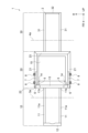
- 1 is a schematic plan view showing a portion of a vehicle equipped with a vehicle side structure according to an embodiment of the present disclosure.
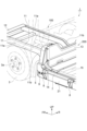
- 1 is an enlarged perspective view showing a portion of a vehicle equipped with a vehicle side structure according to an embodiment of the present disclosure;
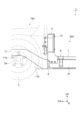
- 1 is an enlarged side view showing a portion of a vehicle equipped with a vehicle side structure according to an embodiment of the present disclosure.
- FIG. 4 is a perspective view showing an example of a configuration of a cover.
- FIG. 4 is a cross-sectional view showing an example of a configuration of a cover.
- FIG. 2 is a perspective view showing an example of a configuration of a vertical joist and a mounting bracket.
- FIG. 4 is a cross-sectional view showing an example of the configuration of a vertical joist and a mounting bracket.
- up, down, left, right and up refer to the up, down, left, right and up of the vehicle (unless otherwise specified).
- Front and rear corresponds to the front-to-rear direction of the vehicle
- left and right corresponds to the width direction of the vehicle
- up and down corresponds to the height direction of the vehicle.
- UP indicates the top of the vehicle
- FR indicates the front of the vehicle
- R indicates the right side of the vehicle.
- Vehicle 1 shown in Figures 1 to 4 is configured as an electric vehicle equipped with a motor (not shown) as a drive source.
- Vehicle 1 is, for example, a commercial vehicle such as a truck.
- Vehicle 1 may be, for example, any of a large vehicle, a medium-sized vehicle, a normal passenger car, a small vehicle, and a light vehicle.
- Vehicle 1 may also be a hybrid vehicle further equipped with an engine as a drive source.
- FIG. 1 is a schematic side view showing a portion of a vehicle equipped with a vehicle side structure according to an embodiment of the present disclosure.
- FIG. 2 is a schematic plan view showing a portion of a vehicle equipped with a vehicle side structure according to an embodiment of the present disclosure.
- a vehicle 1 includes a frame 2.
- the frame 2 extends along the fore-and-aft direction as a whole.
- the frame 2 has a front frame portion 10, an intermediate frame portion 20, and a rear frame portion 30.
- the front frame portion 10, the intermediate frame portion 20, and the rear frame portion 30 are arranged in order from the front side in the fore-and-aft direction.
- the front frame section 10 has a pair of first side rails 11 and a cross member 12.
- the middle frame section 20 has a pair of second side rails 21 and cross members 22, 23.
- the rear frame section 30 has a pair of third side rails 31 and a cross member 32.
- the pair of first side rails 11 extend in the front-rear direction and face each other in the vehicle width direction.
- Each first side rail 11 has a main body portion 11a that extends straight in the front-rear direction, and an extension portion 11b that extends rearward from the main body portion 11a.
- the rear end of the extension portion 11b is connected to the cross member 22 of the intermediate frame portion 20.
- the extension portion 11b extends straight, inclining downward as it approaches the rear.
- the cross member 12 extends straight in the vehicle width direction and is connected to the front end of each first side rail 11.
- the pair of second side rails 21 extend straight in the front-rear direction and face each other in the vehicle width direction.
- the distance between the pair of second side rails 21 in the vehicle width direction is wider than the distance between the pair of first side rails 11 in the vehicle width direction. This allows a large space to be secured for arranging the battery 15, which will be described later.
- the cross member 22 extends straight in the vehicle width direction and is connected to the front ends of each of the second side rails 21.
- the cross member 23 extends straight in the vehicle width direction and is connected to the rear ends of each of the second side rails 21.
- the cross members 22, 23 face each other in the front-rear direction.
- the pair of third side rails 31 extend straight in the front-rear direction and face each other in the vehicle width direction.
- the distance between the pair of third side rails 31 in the vehicle width direction is approximately equal to the distance between the pair of first side rails 11 in the vehicle width direction and is narrower than the distance between the pair of second side rails 21 in the vehicle width direction.
- Each third side rail 31 is connected to a cross member 23 of the intermediate frame portion 20.
- the cross member 32 extends straight in the vehicle width direction and is connected to the rear end of each third side rail 31.
- the front frame portion 10 is located above the intermediate frame portion 20 in the vertical direction of the vehicle. More specifically, the upper edge of the main body portion 11a of the pair of first side rails 11 is located above the upper edge of the pair of second side rails 21. That is, the frame 2 is bent at the boundary portion P between the front frame portion 10 and the intermediate frame portion 20 so that the front frame portion 10 is located above the intermediate frame portion 20. As a result, the frame 2 has a stepped frame structure in which a step portion S is formed between the front frame portion 10 and the intermediate frame portion 20.
- the extension portion 11b extends at an angle, but the extension portion 11b may extend straight in the vertical direction. That is, the frame 2 may be bent at 90 degrees at the boundary portion P. Alternatively, the extension portion 11b may extend in a curved manner.
- the intermediate frame portion 20 and the rear frame portion 30 are formed flat.
- the upper edges of the pair of second side rails 21 are located on the same plane as the upper edges of the pair of third side rails 31. Therefore, the front frame portion 10 is located higher than the intermediate frame portion 20 and the rear frame portion 30.
- the frame 2 supports a vehicle body (not shown) that constitutes the passenger compartment.
- the vehicle body is arranged, for example, so that the bottom wall (floor surface) is located on the frame 2.
- a cab 100 having a driver's seat is provided at the front of the vehicle 1.
- Space for loading luggage for example, is provided at the center and rear of the vehicle 1. That is, a loading platform 200 is provided at the center of the vehicle 1.
- An entrance and exit for loading and unloading luggage is provided at the rear of the vehicle 1.
- the front, center, and rear of the vehicle 1 are parts that overlap with the front frame portion 10, the intermediate frame portion 20, and the rear frame portion 30, respectively, when viewed from the top and bottom. Therefore, the cab 100 is located in a position corresponding to the front frame portion 10.
- the loading platform 200 is located in a position corresponding to the intermediate frame portion 20.
- the frame 2 also supports an axle 3a connected to the front wheels 3 and an axle 4a connected to the rear wheels 4.
- the vehicle 1 is front-wheel drive, and the front wheels 3 are the drive wheels.
- the axle 3a is supported by the front frame portion 10, and the axle 4a is supported by the rear frame portion 30.
- the axle 3a is located below the first side rail 11, and the axle 4a is located above the third side rail 31. Since the axle 4a is located above the third side rail 31, it is easy to adopt a layout in which the frame 2 extends straight across the intermediate frame portion 20 and the rear frame portion 30.
- FIG. 3 is an enlarged perspective view showing a portion of a vehicle having a vehicle side structure according to an embodiment of the present disclosure.
- FIG. 4 is an enlarged side view showing a portion of a vehicle having a vehicle side structure according to an embodiment of the present disclosure.
- the vehicle 1 further includes a box 13, a pair of harnesses 14, and a battery 15.
- the box 13, the pair of harnesses 14, and the battery 15 are components for applying a high voltage of, for example, 200 V or more.
- the box 13 is arranged vertically on the top of the cross member 22 (the upper front part of the intermediate frame section 20).
- the box 13 contains a relay and a fuse.
- the pair of harnesses 14 electrically connect the high-voltage components inside the box 13 to the battery 15 described below.
- One end of each harness 14 is housed inside the box 13, and the other end of each harness 14 is connected to the battery 15.
- the entirety of each harness 14 is located between the pair of second side rails 21.
- each harness 14 is located above the second side rails 21.
- the battery 15 supplies power to a motor (not shown) which is a drive source.
- the battery 15 is mounted on the intermediate frame portion 20 of the frame 2. More specifically, the battery 15 is fixed to each second side rail 21 and the cross members 22, 23. When viewed from the top-bottom direction, the entire battery 15 is located between the pair of second side rails 21. The position of the upper end surface of the battery 15 is higher than the position of the upper end surfaces of the second side rails 21.
- the vehicle 1 further includes a pair of covers 5, a pair of protectors 6, and a pair of vertical joists 7.
- the pair of covers 5, the pair of protectors 6, and the pair of vertical joists 7 are protective members that protect the box 13, the pair of harnesses 14, and the battery 15 described above, respectively.
- the pair of covers 5 are protective members that protect the box 13 and the harness 14 connected to the box 13.
- the pair of covers 5 are each provided on the outside of the box 13 in the left-right direction (vehicle width direction). When viewed from the top-bottom direction, the pair of covers 5 are located on the cross member 22. The pair of covers 5 protrude in the left-right direction.
- FIG. 5 is a perspective view showing an example of the configuration of each cover 5.
- FIG. 5 shows the cover 5 provided on the right side in the left-right direction.
- FIG. 6(a) and FIG. 6(b) are cross-sectional views showing an example of the configuration of each cover 5.
- FIG. 6(a) corresponds to the cross-sectional view taken along line VI(a)-VI(a) in FIG. 5
- FIG. 6(b) corresponds to the cross-sectional view taken along line VI(b)-VI(b) in FIG. 5.
- Each cover 5 has an attachment portion 51, a front portion 52, a middle portion 53, and a rear portion 54.
- the attachment portion 51, the front portion 52, the middle portion 53, and the rear portion 54 are arranged in sequence from the front in the front-to-rear direction.
- the front portion 52, the middle portion 53, and the rear portion 54 are connected to each other to form a space Q.
- a part of the harness 14 is housed in the space Q.
- the cover 5 is formed from a plate material such as aluminum or iron, for example.
- the mounting portion 51 is formed with a cross section that is roughly L-shaped when viewed from above in the vertical direction.
- the mounting portion 51 has a fixing portion 51a that is fixed to the front portion 52 by welding or the like, and a mounting portion 51b that is bent forward in the fore-aft direction from one end of the fixing portion 51a.
- the mounting portion 51 is fixed to a rear cab mount (not shown) that supports the rear side of the cab 100 by fasteners such as bolts.
- the front portion 52 is formed with a cross section that is approximately an inverted L-shape when viewed from above in the vertical direction.
- the front portion 52 is formed with a cross section that is approximately L-shape when viewed from below (one side) in the vertical direction.
- the front portion 52 has a fixed portion 52a that is fixed to the middle portion 53 by welding or the like, and a side wall portion 52b that is bent inward in the left-right direction (to the left in FIG. 6) from one end of the fixed portion 52a.
- the side wall portion 52b is fixed to the fixed portion 51a.
- the middle portion 53 is formed to have a substantially L-shaped cross section when viewed from the front in the front-rear direction.
- the middle portion 53 has a top portion 53a, an upper inclined portion 53b, a lower inclined portion 53c, and a lower portion 53d.
- the outer end of the top portion 53a in the left-right direction (the right side in FIG. 6) is provided with an upper inclined portion 53b that inclines outward in the left-right direction as it approaches the bottom.
- the lower end of the upper inclined portion 53b is provided with a lower inclined portion 53c that inclines outward in the left-right direction as it approaches the bottom.
- the lower end of the lower inclined portion 53c is provided with a lower portion 53d that extends downward in the up-down direction.
- One end of the middle portion 53 is fixed to the fixing portion 52a by welding or the like when viewed from the up-down direction.
- the other end of the middle portion 53 is fixed to the rear portion 54 by welding or the like when viewed from the up-down
- the rear portion 54 is formed with a generally L-shaped cross section when viewed from the top (one side) in the vertical direction.
- the rear portion 54 has a fixed portion 54a fixed to the middle portion 53, and a side wall portion 54b bent inward in the left-right direction (to the left in FIG. 6) from one end of the fixed portion 54a.
- the side wall portion 54b faces the side wall portion 52b in the front-rear direction.
- the middle portion 53 of the cover 5 has a top portion 53a, an upper inclined portion 53b, a lower inclined portion 53c, and a lower portion 53d, so that the dimension of the cover 5 in the left-right direction (vehicle width direction) increases toward the bottom of the cover 5. Therefore, the harness 14 can be effectively accommodated within the space Q in the lower region of the cover 5, and the desired space can be secured around the upper region of the cover 5 in the vehicle 1.
- the pair of protectors 6 are protective members that protect the lower part of the box 13 and the pair of harnesses 14. As shown in Figures 3 and 4, the pair of protectors 6 are provided on the lower side of each cover 5. The pair of protectors 6 are provided outside the lower part of the box 13 and the pair of harnesses 14 in the left-right direction. Figures 3 and 4 show the protector 6 provided on the left side in the left-right direction.
- Each protector 6 is provided outside each cover 5 in the left-right direction when viewed from the top-bottom direction.
- Each protector 6 is formed in a substantially L-shaped cross section when viewed from one side in the front-rear direction.
- the lower end of each protector 6 is fixed to the front end of each second side rail 21 by a bolt or the like.
- the upper end of each protector 6 is bent inward in the left-right direction toward the lower portion 53d of the middle portion 53 of the cover 5.
- the height position of the upper end of each protector 6 is the same as the height position of the lower portion 53d.
- the upper end of each protector 6 may or may not be in contact with the lower portion 53d.
- Each protector 6 is formed from a plate material such as aluminum or iron.
- the pair of vertical joists 7 are protective members that protect the pair of harnesses 14 and the battery 15. When viewed from the top-bottom direction, the pair of vertical joists 7 are located on each of the second side rails 21. The pair of vertical joists 7 are provided outside the pair of harnesses 14 and the battery 15 in the left-right direction. The pair of vertical joists 7 face each other in the width direction.
- FIG. 7 is a perspective view showing an example of the configuration of each vertical joist 7 and each mounting bracket 8 (described later).
- FIG. 7 shows a vertical joist 7 provided on the left side in the left-right direction.
- FIG. 8 is a cross-sectional view showing an example of the configuration of each vertical joist 7 and each mounting bracket 8.
- FIG. 8 corresponds to the cross-sectional view taken along line VIII-VIII in FIG. 7.
- Each vertical joist 7 is formed of a plate material such as aluminum or iron.
- Each vertical joist 7 has a generally U-shaped cross section when viewed from the front-to-rear direction. Each vertical joist 7 extends in the front-to-rear direction. Each vertical joist 7 is fixed to each second side rail 21 via each mounting bracket 8.
- Each mounting bracket 8 functions as a bracket (connecting member) that fixes each vertical joist 7 to each second side rail 21.
- Each mounting bracket 8 has an attachment portion 8a, a seat plate 8b, and a fixing portion 8c.
- Each mounting bracket 8 is formed from a plate material such as aluminum or iron.
- the mounting portion 8a is formed in a roughly U-shape when viewed from the top and bottom.
- the mounting portion 8a is fixed to the vertical joist 7 by fasteners such as bolts.
- the seat plate 8b is provided on the lower part of the mounting portion 8a.
- the seat plate 8b is fixed to the fixing portion 8c by fasteners such as bolts.
- the fixing portion 8c is formed in a roughly inverted L-shape in cross section.
- the fixing portion 8c is fixed to the second side rail 21 by fasteners such as bolts.
- the protector 6 first deforms, causing the upper end of the protector 6 to come into contact with the front portion 52, middle portion 53, and rear portion 54 of the cover 5, deforming the cover 5, and the protector 6 comes into contact with the vertical joist 7, causing the vertical joist 7 to deform. This protects the box 13, harness 14, and battery 15.
- the side structure of the vehicle 1 includes a cover 5 disposed between the cab 100 and the loading platform 200 of the vehicle 1 and projecting outward in the vehicle width direction of the vehicle 1, a protector 6 provided under the cover 5 and fixed to the second side rail 21 (frame 2) of the vehicle 1, and a vertical joist 7 fixed to the second side rail 21 via a mount bracket 8 (connecting member) and extending in the front-rear direction of the vehicle 1.
- the cover 5, protector 6, and vertical joist 7 can cover electrical equipment such as high-voltage components mounted behind the cab 100 of the vehicle 1. This makes it possible to protect the electrical equipment even if an impact force is applied to the vehicle 1 due to a side collision.
- the cover 5, protector 6, and vertical joist 7 can be provided regardless of the structure or layout of the vehicle 1.
- the versatile side structure which is not dependent on the structure of the vehicle 1, can protect the equipment mounted on the vehicle 1 from impact during a side collision.
- EA material shock absorbing material
- the frame 2 has a front frame portion 10, an intermediate frame portion 20, and a rear frame portion 30 that extend along the front-rear direction, and is bent at a boundary portion P between the front frame portion 10 and the intermediate frame portion 20 so that the front frame portion 10 is positioned higher than the intermediate frame portion 20 and the rear frame portion 30, and the protector 6 is fixed to the intermediate frame portion 20.
- the intermediate frame portion 20 and the rear frame portion 30 are positioned lower than the front frame portion 10, so the floor surface of the loading platform 200 is lower. This makes it easier for workers to get on and off the loading platform 200.
- the space for placing the battery 15 on the loading platform 200 can be made larger.
- the cover 5 has a front portion 52, an intermediate portion 53, and a rear portion 54 arranged in sequence from the front side of the vehicle 1, the front portion 52 is formed in a substantially L-shaped cross section when viewed from one side in the vertical direction of the vehicle 1, the rear portion 54 is formed in a substantially L-shaped cross section when viewed from the other side in the vertical direction of the vehicle 1, and the front portion 52 and the rear portion 54 are fixed to the intermediate portion 53.
- the rear portion 55 shown by the imaginary line in FIG. 6(a) is the conventional structure of the rear portion 54.
- the rear portion 54 has a structure that protrudes outward in the left-right direction compared to the conventional rear portion 55.
- the cover 5 has a structure that is less likely to deform when subjected to an impact such as a side collision than the conventional structure.
- the width dimension (front-rear dimension) of the outermost portion in the left-right direction of the cover 5 is secured, so that the impact received during a side collision is reduced. Therefore, the equipment mounted on the vehicle 1 can be further protected from the impact during a side collision.
- the protector 6 is formed with a cross section that is approximately L-shaped when viewed from one side in the front-to-rear direction, but the structure of the protector 6 is not limited to this shape and can be modified in various ways.
- the frame 2 has a stepped frame structure in which a step portion S is formed between the front frame portion 10 and the middle frame portion 20, but this is not particularly limited to this form, and the frame 2 may extend straight in the front-to-rear direction without inclining from the front end to the rear end.
- each vertical joist 7 is formed with a cross section that is approximately U-shaped when viewed from the front-to-back direction, but this is not limited to this shape.
- each vertical joist 7 may be formed with a cross section that is approximately U-shaped or approximately L-shaped when viewed from the front-to-back direction as long as the required strength is ensured.
Landscapes
- Engineering & Computer Science (AREA)
- Chemical & Material Sciences (AREA)
- Combustion & Propulsion (AREA)
- Transportation (AREA)
- Mechanical Engineering (AREA)
- Body Structure For Vehicles (AREA)
- Arrangement Or Mounting Of Propulsion Units For Vehicles (AREA)
Abstract
L'invention concerne une structure latérale d'un véhicule comprenant : un couvercle qui est disposé entre une cabine du véhicule et une plateforme de chargement, le couvercle faisant saillie vers l'extérieur dans la direction de la largeur de véhicule du véhicule ; un dispositif de protection qui est disposé sur le côté inférieur du couvercle et qui est fixé à un cadre du véhicule ; et des poutres de support longitudinales qui sont fixées au cadre par l'intermédiaire d'éléments de liaison, les poutres de support longitudinales s'étendant dans la direction avant-arrière du véhicule.
Applications Claiming Priority (2)
| Application Number | Priority Date | Filing Date | Title |
|---|---|---|---|
| JP2023-096345 | 2023-06-12 | ||
| JP2023096345A JP2024177930A (ja) | 2023-06-12 | 2023-06-12 | 車両の側部構造 |
Publications (1)
| Publication Number | Publication Date |
|---|---|
| WO2024257765A1 true WO2024257765A1 (fr) | 2024-12-19 |
Family
ID=93851987
Family Applications (1)
| Application Number | Title | Priority Date | Filing Date |
|---|---|---|---|
| PCT/JP2024/021210 Ceased WO2024257765A1 (fr) | 2023-06-12 | 2024-06-11 | Structure latérale de véhicule |
Country Status (2)
| Country | Link |
|---|---|
| JP (1) | JP2024177930A (fr) |
| WO (1) | WO2024257765A1 (fr) |
Citations (4)
| Publication number | Priority date | Publication date | Assignee | Title |
|---|---|---|---|---|
| JPS5181316A (fr) * | 1975-10-22 | 1976-07-16 | Mitsubishi Motors Corp | |
| JPS55102615U (fr) * | 1979-01-13 | 1980-07-17 | ||
| JP2022025814A (ja) * | 2020-07-30 | 2022-02-10 | ダイムラー・アクチェンゲゼルシャフト | 車両用バッテリパックの支持装置 |
| JP2022150297A (ja) * | 2021-03-26 | 2022-10-07 | 日野自動車株式会社 | 車両のボデー構造 |
-
2023
- 2023-06-12 JP JP2023096345A patent/JP2024177930A/ja active Pending
-
2024
- 2024-06-11 WO PCT/JP2024/021210 patent/WO2024257765A1/fr not_active Ceased
Patent Citations (4)
| Publication number | Priority date | Publication date | Assignee | Title |
|---|---|---|---|---|
| JPS5181316A (fr) * | 1975-10-22 | 1976-07-16 | Mitsubishi Motors Corp | |
| JPS55102615U (fr) * | 1979-01-13 | 1980-07-17 | ||
| JP2022025814A (ja) * | 2020-07-30 | 2022-02-10 | ダイムラー・アクチェンゲゼルシャフト | 車両用バッテリパックの支持装置 |
| JP2022150297A (ja) * | 2021-03-26 | 2022-10-07 | 日野自動車株式会社 | 車両のボデー構造 |
Also Published As
| Publication number | Publication date |
|---|---|
| JP2024177930A (ja) | 2024-12-24 |
Similar Documents
| Publication | Publication Date | Title |
|---|---|---|
| CN112140860B (zh) | 车辆车身结构及包括该车辆车身结构的车辆 | |
| US11446998B2 (en) | Rear structure of vehicle | |
| CN110239627B (zh) | 车辆后部构造 | |
| JP5083465B2 (ja) | ハイブリッド車の車両構造 | |
| EP2712748B1 (fr) | Structure de cadre destinée à être utilisée dans un véhicule électrique de type camion | |
| EP3747704B1 (fr) | Structure arrière de carrosserie d'un véhicule, structure de carrosserie d'un véhicule et véhicule | |
| JP6181723B2 (ja) | 車体構造及び車載用バッテリー | |
| US7631926B2 (en) | Side impact crash event body structure improvement | |
| JP7322790B2 (ja) | 車両の下部構造 | |
| CN114590326A (zh) | 用于电池电动车辆的车身底板 | |
| CN104995051A (zh) | 电动汽车 | |
| KR20210071116A (ko) | 고전압배터리가 장착되는 차체 | |
| JP7323872B2 (ja) | 電動車両における電源ユニット及び後部シートの配置構造 | |
| JP7769512B2 (ja) | 電池モジュールの保護構造 | |
| JP2014019260A (ja) | 電池パックの位置決めピンブラケット | |
| KR20220064789A (ko) | 고전압배터리가 구비된 차체 | |
| CN214028868U (zh) | 车身后部构造 | |
| US20240034141A1 (en) | Vehicle body rear structure | |
| JP7563623B2 (ja) | 電動車両 | |
| JP4479299B2 (ja) | 車体下部構造 | |
| WO2024257765A1 (fr) | Structure latérale de véhicule | |
| JP7601200B2 (ja) | 車載機器の固定構造 | |
| JP7415240B2 (ja) | 車両の下部構造 | |
| JP7650686B2 (ja) | 車両 | |
| JP7619522B2 (ja) | 車両の高電圧部品の保護構造 |
Legal Events
| Date | Code | Title | Description |
|---|---|---|---|
| 121 | Ep: the epo has been informed by wipo that ep was designated in this application |
Ref document number: 24823380 Country of ref document: EP Kind code of ref document: A1 |
|
| NENP | Non-entry into the national phase |
Ref country code: DE |