WO2024257767A1 - Medical system and liquid circulation system - Google Patents
Medical system and liquid circulation system Download PDFInfo
- Publication number
- WO2024257767A1 WO2024257767A1 PCT/JP2024/021221 JP2024021221W WO2024257767A1 WO 2024257767 A1 WO2024257767 A1 WO 2024257767A1 JP 2024021221 W JP2024021221 W JP 2024021221W WO 2024257767 A1 WO2024257767 A1 WO 2024257767A1
- Authority
- WO
- WIPO (PCT)
- Prior art keywords
- liquid
- period
- body cavity
- balloon
- amount
- Prior art date
- Legal status (The legal status is an assumption and is not a legal conclusion. Google has not performed a legal analysis and makes no representation as to the accuracy of the status listed.)
- Ceased
Links
Images











Classifications
-
- A—HUMAN NECESSITIES
- A61—MEDICAL OR VETERINARY SCIENCE; HYGIENE
- A61M—DEVICES FOR INTRODUCING MEDIA INTO, OR ONTO, THE BODY; DEVICES FOR TRANSDUCING BODY MEDIA OR FOR TAKING MEDIA FROM THE BODY; DEVICES FOR PRODUCING OR ENDING SLEEP OR STUPOR
- A61M27/00—Drainage appliance for wounds or the like, i.e. wound drains, implanted drains
- A61M27/002—Implant devices for drainage of body fluids from one part of the body to another
- A61M27/006—Cerebrospinal drainage; Accessories therefor, e.g. valves
-
- A—HUMAN NECESSITIES
- A61—MEDICAL OR VETERINARY SCIENCE; HYGIENE
- A61M—DEVICES FOR INTRODUCING MEDIA INTO, OR ONTO, THE BODY; DEVICES FOR TRANSDUCING BODY MEDIA OR FOR TAKING MEDIA FROM THE BODY; DEVICES FOR PRODUCING OR ENDING SLEEP OR STUPOR
- A61M1/00—Suction or pumping devices for medical purposes; Devices for carrying-off, for treatment of, or for carrying-over, body-liquids; Drainage systems
-
- A—HUMAN NECESSITIES
- A61—MEDICAL OR VETERINARY SCIENCE; HYGIENE
- A61M—DEVICES FOR INTRODUCING MEDIA INTO, OR ONTO, THE BODY; DEVICES FOR TRANSDUCING BODY MEDIA OR FOR TAKING MEDIA FROM THE BODY; DEVICES FOR PRODUCING OR ENDING SLEEP OR STUPOR
- A61M25/00—Catheters; Hollow probes
- A61M25/10—Balloon catheters
- A61M25/1018—Balloon inflating or inflation-control devices
- A61M25/10184—Means for controlling or monitoring inflation or deflation
-
- A—HUMAN NECESSITIES
- A61—MEDICAL OR VETERINARY SCIENCE; HYGIENE
- A61M—DEVICES FOR INTRODUCING MEDIA INTO, OR ONTO, THE BODY; DEVICES FOR TRANSDUCING BODY MEDIA OR FOR TAKING MEDIA FROM THE BODY; DEVICES FOR PRODUCING OR ENDING SLEEP OR STUPOR
- A61M27/00—Drainage appliance for wounds or the like, i.e. wound drains, implanted drains
- A61M27/002—Implant devices for drainage of body fluids from one part of the body to another
- A61M2027/004—Implant devices for drainage of body fluids from one part of the body to another with at least a part of the circuit outside the body
-
- A—HUMAN NECESSITIES
- A61—MEDICAL OR VETERINARY SCIENCE; HYGIENE
- A61M—DEVICES FOR INTRODUCING MEDIA INTO, OR ONTO, THE BODY; DEVICES FOR TRANSDUCING BODY MEDIA OR FOR TAKING MEDIA FROM THE BODY; DEVICES FOR PRODUCING OR ENDING SLEEP OR STUPOR
- A61M2202/00—Special media to be introduced, removed or treated
- A61M2202/02—Gases
- A61M2202/0208—Oxygen
-
- A—HUMAN NECESSITIES
- A61—MEDICAL OR VETERINARY SCIENCE; HYGIENE
- A61M—DEVICES FOR INTRODUCING MEDIA INTO, OR ONTO, THE BODY; DEVICES FOR TRANSDUCING BODY MEDIA OR FOR TAKING MEDIA FROM THE BODY; DEVICES FOR PRODUCING OR ENDING SLEEP OR STUPOR
- A61M2202/00—Special media to be introduced, removed or treated
- A61M2202/04—Liquids
- A61M2202/0464—Cerebrospinal fluid
-
- A—HUMAN NECESSITIES
- A61—MEDICAL OR VETERINARY SCIENCE; HYGIENE
- A61M—DEVICES FOR INTRODUCING MEDIA INTO, OR ONTO, THE BODY; DEVICES FOR TRANSDUCING BODY MEDIA OR FOR TAKING MEDIA FROM THE BODY; DEVICES FOR PRODUCING OR ENDING SLEEP OR STUPOR
- A61M2210/00—Anatomical parts of the body
- A61M2210/06—Head
- A61M2210/0693—Brain, cerebrum
-
- A—HUMAN NECESSITIES
- A61—MEDICAL OR VETERINARY SCIENCE; HYGIENE
- A61M—DEVICES FOR INTRODUCING MEDIA INTO, OR ONTO, THE BODY; DEVICES FOR TRANSDUCING BODY MEDIA OR FOR TAKING MEDIA FROM THE BODY; DEVICES FOR PRODUCING OR ENDING SLEEP OR STUPOR
- A61M2210/00—Anatomical parts of the body
- A61M2210/10—Trunk
- A61M2210/1003—Spinal column
Definitions
- the present invention relates to a medical system and a fluid circulation system used to treat brain diseases.
- cerebral infarction When a brain disease such as cerebral infarction occurs, the blood flow that supplies oxygen to brain cells is blocked, which can cause damage to the brain cells. Therefore, when a cerebral infarction occurs, early reperfusion of blood flow is necessary.
- a highly oxygenated solution such as oxygenated cerebrospinal fluid into the body cavity where the cerebrospinal fluid is present in the patient, thereby directly supplying oxygen to oxygen-deficient brain cells.
- Patent Document 1 discloses a catheter system capable of injecting liquid into and suctioning liquid from a living body using a single lumen.
- the catheter system described in Patent Document 1 comprises a catheter, an injection drive unit that supplies fluid to an injection port via the lumen of the tube body, a suction drive unit that suctions fluid from the suction port via the lumen of the tube body, a detection unit that detects the state of intracranial pressure, and a control unit that controls the injection drive unit and the suction drive unit.
- the suction port of the catheter is in a closed state when the injection port of the catheter is in an open state.
- the injection port of the catheter is also in a closed state when the suction port of the catheter is in an open state.
- the control unit alternately operates the injection drive unit and the suction drive unit so that the state of intracranial pressure detected by the detection unit is within a certain range.
- intracranial pressure when a liquid such as a highly oxygenated solution is injected into a body cavity for the purpose of treating a brain disease, it is necessary to maintain intracranial pressure within a certain range.
- the normal range for intracranial pressure is approximately 5 mmHg or more and 15 mmHg or less. Fluctuations in pressure from inside the skull to inside the spinal cavity can cause brain damage. For example, if intracranial pressure rises to 20 mmHg or more, there is a risk of intracranial hypertension (i.e., various symptoms that develop when brain tissue is placed under stress). On the other hand, if intracranial pressure falls to 5 mmHg or less, there is a risk of low cerebrospinal fluid pressure syndrome (i.e., various symptoms that develop when brain tissue cannot maintain its position).
- Body cavities in which cerebrospinal fluid exists are almost entirely closed spaces. Therefore, in order to maintain intracranial pressure within a constant range, it is necessary to maintain the amount of cerebrospinal fluid within the body cavity within a constant range. In order to maintain the amount of cerebrospinal fluid within a body cavity within a constant range, it is necessary to quickly expel an amount of cerebrospinal fluid equal to the amount of fluid injected into the body cavity.
- the inlet of the injection catheter could be placed near the brain, and the outlet of the drainage catheter placed near the lumbar vertebrae, thereby providing a sufficient distance between the injection and drainage ports and minimizing the effects of local steady flow.
- the catheter when attempting to insert a catheter close to the brain, the catheter would have to be inserted a long distance into the curved subarachnoid space, which is surrounded by nerve tissue such as the spinal cord. Inserting such a catheter deep into the subarachnoid space carries the risk of damaging the nerve tissue, so it is desirable to insert the catheter as short as possible.
- the liquid circulation circuit it is desirable for the liquid circulation circuit to be a closed system to prevent infection.
- the liquid circulation circuit is a closed system, there is a risk that the total volume of the liquid will increase compared to the volume at the beginning of treatment due to bubbles being generated within the circulation circuit due to the cavitation phenomenon, or that the total volume of the liquid will decrease compared to the volume at the beginning of treatment due to water being lost through evaporation during the process of oxygenating the cerebrospinal fluid. If the total volume of the liquid increases or decreases in a closed circulation circuit, there is a risk that intracranial pressure cannot be maintained within a constant range.
- the present invention is (1) a medical system for injecting a liquid into a body cavity in which cerebrospinal fluid of a subject is present and discharging the liquid present in the body cavity from the body cavity, the medical system being characterized in that it has a control unit that executes control to set a first period during which the liquid is injected into the body cavity and is not discharged from the body cavity, and a second period during which the liquid is not injected into the body cavity and is discharged from the body cavity, alternately repeating the first period and the second period, and setting the amount of the liquid injected in the first period to be substantially the same as the amount of the liquid discharged in the second period.
- the control unit injects liquid into the body cavity during the first period, and does not discharge the liquid from the body cavity. Also, the control unit does not inject liquid into the body cavity during the second period, and discharges the liquid from the body cavity.
- the control unit alternates between the first period and the second period, and makes the amount of liquid injected and the amount of liquid discharged substantially the same. As a result, the injection and discharge of liquid are alternately repeated in the same amount, as long as the allowable fluctuation range of the intracranial pressure is not exceeded. Therefore, the injection and discharge of liquid are not performed simultaneously, and the occurrence of a local steady flow of the liquid injected from the injection port into the body cavity toward the discharge port can be suppressed.
- the liquid injected into the body cavity flows toward the treatment area of the brain according to the injection direction and injection flow rate.
- the liquid and the cerebrospinal fluid are stirred by turbulence caused by the resistance between the liquid injected into the body cavity and the cerebrospinal fluid in the body cavity.
- diffusion due to the concentration difference of oxygen and the like contained in the liquid progresses.
- the liquid can be efficiently delivered to the treatment area of the brain.
- the amount of fluid injected is essentially the same as the amount of fluid removed, the amount of cerebrospinal fluid in the cavity can be kept within a constant range. This helps prevent large fluctuations in intracranial pressure.
- control unit further sets a third period between the first period and the second period, during which the liquid is not injected into the body cavity and the liquid is not discharged from the body cavity.
- diffusion due to the difference in concentration of oxygen and the like contained in the liquid progresses more according to the length of the third period, thereby enabling the liquid to be delivered to the treatment area of the brain more efficiently.
- the third period is longer than the first period.
- the time during which diffusion due to the concentration difference of oxygen and the like contained in the liquid progresses is longer than the time during which the liquid is injected, which allows the liquid to be delivered to the treatment area of the brain more efficiently.
- the third period of time is 1 second or longer. According to the medical system of (5) above, time can be secured for diffusion due to the concentration difference of oxygen and the like contained in the liquid to proceed, thereby enabling the liquid to be efficiently delivered to the treatment area of the brain.
- control unit further sets the third period between the second period and the first period, and that the first time of the third period set between the first period and the second period is longer than the second time of the third period set between the second period and the first period.
- the first time of the pause period (i.e., the third period) between the injection and discharge of the liquid is longer than the second time of the pause period (i.e., the third period) between the discharge and injection of the liquid. This more reliably prevents the occurrence of a local steady flow of the liquid injected from the injection port into the body cavity toward the discharge port, and more reliably ensures time for diffusion due to concentration differences in oxygen and other substances contained in the liquid to proceed. This allows the liquid to be delivered to the treatment area of the brain more efficiently.
- a discharge rate of the liquid during the second period is slower than a supply rate of the liquid during the first period.
- the discharge speed of the liquid in the second period is slower than the injection speed of the liquid in the first period, the speed at which the liquid injected from the injection port into the body cavity moves toward the outlet can be suppressed, and it is possible to ensure that the liquid has enough time to diffuse toward the brain immediately after being injected from the injection port into the body cavity, thereby enabling the liquid to be efficiently delivered to the treatment area of the brain.
- the control unit initially sets a 0th period in which the liquid is injected or discharged in an amount smaller than the injection amount in the first period and the discharge amount in the second period, and starts a period of the first period or the second period in which the liquid moves in a different direction from the 0th period after the 0th period.
- the volume change in the subarachnoid space in the initial zeroth period varies within a range including the original volume. Therefore, it is possible to prevent the volume change from exceeding the allowable variation range. This makes it possible to keep the variation in intracranial pressure within the allowable variation range.
- any of the medical systems (1) to (10) above further includes an injection catheter for injecting the liquid into the body cavity and a drainage catheter for draining the liquid from the body cavity, and it is preferable that the distance between the tip of the injection catheter and the tip of the drainage catheter is 30 centimeters or less when execution of the control begins.
- the injection and discharge of liquid are alternately repeated in equal amounts, so that even if the distance between the tip of the injection catheter and the tip of the discharge catheter is 30 centimeters or less when control execution begins, it is possible to suppress the occurrence of a local steady flow of liquid injected from the injection port into the body cavity toward the discharge port. This makes it possible to efficiently deliver liquid to the treatment area of the brain without inserting the injection catheter deeply into the living body.
- control unit further executes control to contract a balloon that is placed in the body cavity and capable of expanding and contracting during the first period, and to expand the balloon during the second period.
- the control unit injects liquid into the body cavity during the first period, but does not discharge the liquid from the body cavity, and further contracts the balloon placed in the body cavity by the same volume as the liquid.
- the control unit can suppress fluctuations in the volume of the body cavity as a closed space during the first period when the liquid is injected into the body cavity, thereby suppressing fluctuations in intracranial pressure.
- the control unit does not inject liquid into the body cavity during the second period, but discharges the liquid from the body cavity, and further expands the balloon placed in the body cavity by the same volume as the liquid.
- the control unit can suppress fluctuations in the volume of the body cavity as a closed space during the second period when the liquid is discharged from the body cavity, thereby suppressing fluctuations in intracranial pressure.
- slight volume fluctuations may occur due to the difference between the amount of liquid discharged and the amount of balloon expansion, or the difference between the amount of liquid injected and the amount of balloon deflation.
- the amount of volume fluctuation is within the allowable range of the subject's body cavity's own volume fluctuation ability, i.e., the compliance for maintaining intracavity pressure. Therefore, the body deforms in response to a decrease or increase in the amount of liquid, and the volume fluctuations can be countered while maintaining a constant intracranial pressure.
- control unit simultaneously injects the liquid and contracts the balloon during the first period, and simultaneously discharges the liquid and expands the balloon during the second period.
- the control unit simultaneously injects the liquid and deflates the balloon during the first period.
- the control unit can further suppress fluctuations in the volume of the body cavity during the first period when the liquid is injected into the body cavity. This further suppresses fluctuations in intracranial pressure during the first period.
- the control unit simultaneously discharges the liquid and expands the balloon during the second period. This further suppresses fluctuations in the volume of the body cavity during the second period when the liquid is discharged from the body cavity. This further suppresses fluctuations in intracranial pressure during the second period.
- control unit sets the amount of contraction of the balloon during the first period to be substantially equal to the amount of liquid injected, and sets the amount of expansion of the balloon during the second period to be substantially equal to the amount of liquid discharged.
- the control unit sets the balloon contraction amount to be substantially the same as the amount of liquid injected during the first period. Therefore, the amount of liquid increased in the body cavity (i.e., the volume) is substantially the same as the amount by which the balloon contracted in the body cavity (i.e., the volume). Therefore, the volume of the body cavity does not change substantially during the first period. This more reliably suppresses fluctuations in intracranial pressure during the first period.
- the control unit sets the balloon expansion amount to be substantially the same as the amount of liquid discharged during the second period. Therefore, the amount of liquid decreased in the body cavity (i.e., the volume) is substantially the same as the amount by which the balloon expanded in the body cavity (i.e., the volume). Therefore, the volume of the body cavity does not change substantially during the second period. This more reliably suppresses fluctuations in intracranial pressure during the second period.
- control unit further sets a third period between the first period and the second period and between the second period and the first period during which the liquid is not injected into the body cavity and the liquid is not discharged from the body cavity, and maintains the balloon in the contracted state during the third period between the first period and the second period, and maintains the balloon in the expanded state during the third period between the second period and the first period.
- the present invention (16) is a liquid circulation system that injects a liquid into a body cavity in which cerebrospinal fluid is present and discharges the liquid outside the body cavity, the liquid circulation system comprising an injection catheter that injects the liquid into the body cavity, a discharge catheter that discharges the liquid from inside the body cavity to outside the body cavity, a liquid delivery line connected to the injection catheter, a liquid drainage line connected to the drainage catheter, a first liquid delivery unit provided on the liquid delivery line and moving the liquid, a second liquid delivery unit provided on the drainage line and moving the liquid, and a single control unit that controls the first liquid delivery unit and the second liquid delivery unit.
- the liquid circulation system of (16) above is divided into a circuit including the injection catheter and the discharge catheter (i.e., the biological circuit section), and a circuit including the liquid feed line connected to the injection catheter and the liquid drain line connected to the drain catheter (i.e., the system circuit section).
- a first liquid feed section provided on the liquid feed line for moving the liquid and a second liquid feed section provided on the liquid drain line for moving the liquid function as a liquid feed section shared by the biological circuit section and the system circuit section.
- the system circuit section can respond to an increase in the total volume of liquid caused by cavitation and a decrease in the total volume of liquid caused by evaporation while maintaining the condition on the biological side, and the increase or decrease in the liquid in the biological circuit can be minimized. This makes it possible to suppress fluctuations in intracranial pressure.
- the liquid circulation system of (16) above further includes a liquid storage section that stores at least one of the liquid to be injected into the body cavity and the liquid discharged from the body cavity, and a liquid treatment device that is provided in the liquid delivery line between the liquid storage section and the first liquid delivery section and that treats the liquid.
- the liquid treatment device is preferably an oxygenation device that adds oxygen to the liquid discharged outside the body cavity.
- the liquid circulation system described above in (18) enables efficient delivery of highly oxygenated solution to the treatment area of the brain while suppressing fluctuations in intracranial pressure.
- control unit alternately and repeatedly drives the first liquid delivery unit and the second liquid delivery unit.
- the injection and discharge of liquid are repeated alternately in equal amounts, provided that the allowable fluctuation range of intracranial pressure is not exceeded. Therefore, the injection and discharge of liquid are not performed simultaneously, and the occurrence of a local steady flow that occurs when the injection and discharge of liquid are performed simultaneously, that is, a local steady flow in which the liquid injected from the injection port into the body cavity flows toward the discharge port, can be suppressed. Therefore, the liquid injected into the body cavity flows toward the treatment area of the brain according to the injection direction and injection flow rate.
- the liquid and the cerebrospinal fluid are agitated by turbulence caused by resistance between the liquid injected into the body cavity and the cerebrospinal fluid in the body cavity. Furthermore, diffusion progresses due to the concentration difference of oxygen and the like contained in the liquid. This allows the liquid to be efficiently delivered to the treatment area of the brain.
- control unit controls the sum of the injection amount of the liquid ejected while the first liquid delivery unit is operating continuously or intermittently without starting the second liquid delivery unit, and the discharge amount of the liquid ejected while the second liquid delivery unit is operating continuously or intermittently without starting the first liquid delivery unit, from the time of the initial start within a certain range.
- continuous circulation is a method of continuously injecting and discharging the colored water 911, and is a method as a comparative example. That is, as shown in the table shown in Fig. 16, in “continuous circulation", the control unit 21 sets a period during which the colored water 911 is continuously injected and discharged at a flow rate of 20 mL/min.
- “equal volume withdrawal and receipt” is the method of injection and discharge when the control described above with reference to FIGS. 8 to 11 is executed. That is, as shown in the table shown in FIG. 16, in “equal volume withdrawal and receipt," the control unit 21 sets a first period 211 during which the colored water 911 is injected into the tube 55 and is not discharged from the tube 55, and a second period 212 during which the colored water 911 is not injected into the tube 55 and is discharged from the tube 55.
- the duration of the first period 211 is 3 seconds. In the first period 211, the colored water 911 is injected into the tube 55 over 3 seconds at a flow rate of 20 mL/min, so that the amount of colored water 911 injected is 1 mL.
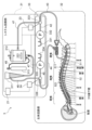
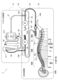
- FIG. 18 is a schematic diagram showing an overview of a liquid circulation system according to this embodiment.
- the liquid circulation system 3 according to the present embodiment circulates a liquid by injecting the liquid into a body cavity and discharging the liquid outside the body cavity.
- An example of the body cavity is a body cavity in which cerebrospinal fluid of a subject is present.
- a case where the liquid injected into the body cavity is a highly oxygenated solution is taken as an example.
- the liquid circulation system 3 includes a system circuit section 31, a biological circuit section 32, and a pump section 33.
- the system circuit section 31 is a section that generates the highly oxygenated solution, adjusts the temperature, and adjusts the total volume of liquid in the circulation circuit, and has a control section 21, a reservoir 311, an oxygenation mechanism 312, and an oxygen supply source 313.
- the oxygenation mechanism 312 of this embodiment is an example of the "liquid treatment device” and “oxygenation device” of the present invention.
- the biological circuit section 32 is a section that injects liquid into the body cavity and expels the liquid from the body cavity, and has a drainage catheter 51 and an injection catheter 52.
- the drainage catheter 51 and the injection catheter 52 are connected to the system circuit section 31 via the pump section 33.
- the drainage catheter 51 and the injection catheter 52 are as described above with reference to Figures 1 to 17.
- the pump section 33 functions as a liquid delivery section shared by the system circuit section 31 and the biological circuit section 32.
- the pump section 33 has a first liquid storage section 331, a first pump 332, a first flow path switching section 333, a second liquid storage section 334, a second pump 335, and a second flow path switching section 336.
- the first pump 332 of this embodiment is an example of the "first liquid delivery section" of the present invention.
- the second pump 335 of this embodiment is an example of the "second liquid delivery section" of the present invention.
- the pump section 33 may have a first drive section 23 and a second drive section 24.
- the oxygenation mechanism 312 supplies the oxygenated cerebrospinal fluid as a highly oxygenated solution to the first flow path switching unit 333 via the first tube 41.
- a hollow fiber type artificial lung for adding oxygen to blood can be used as the oxygenation mechanism 312 in this embodiment.
- the first flow path switching unit 333 is provided at the connection between the first tube 41, the second tube 42, and the third tube 43, and can switch between a flow path connecting the first tube 41 and the second tube 42 and a flow path connecting the second tube 42 and the third tube 43.
- the first drive unit 23 controls the operation of the first flow path switching unit 333 based on a control signal transmitted from the control unit 21, and switches between a flow path connecting the first tube 41 and the second tube 42 and a flow path connecting the second tube 42 and the third tube 43.
- the first tube 41, the second tube 42, and the third tube 43 are an example of a "liquid delivery line" of the present invention, and are connected to the first liquid storage unit 331 and the injection catheter 52.
- the first flow path switching unit 333 is connected to the first liquid storage unit 331 via the second tube 42.
- the first pump 332 is provided in the second tube 42. Examples of the first pump 332 include a roller pump and a syringe pump. The first pump 332 operates based on a control signal sent from the control unit 21, and moves liquid toward the first liquid storage unit 331 or toward the first flow path switching unit 333.
- the first pump 332 When the first pump 332 is driven in the first direction while the first flow path switching unit 333 is connecting the first tube 41 and the second tube 42, the first pump 332 supplies the liquid (i.e., the highly oxygenated solution) generated in the oxygenation mechanism 312 to the first liquid storage unit 331 through the first tube 41 and the second tube 42. As a result, the first liquid storage unit 331 stores the liquid supplied from the oxygenation mechanism 312 through the first tube 41 and the second tube 42. Note that when the first pump 332 is driven in the second direction while the first flow path switching unit 333 is connecting the first tube 41 and the second tube 42, the first pump 332 supplies the liquid stored in the first liquid storage unit 331 to the oxygenation mechanism 312 through the first tube 41 and the second tube 42.
- the liquid i.e., the highly oxygenated solution
- the first pump 332 supplies the liquid stored in the first liquid storage unit 331 to the injection catheter 52 through the second tube 42 and the third tube 43.
- the reservoir 311 is connected to the second flow path switching unit 336 via the sixth tube 46.
- the reservoir 311 is also connected to the oxygenation mechanism 312 via the seventh tube 47.
- the reservoir 311 temporarily stores the cerebrospinal fluid supplied through the sixth tube 46.
- the reservoir 311 then supplies the stored cerebrospinal fluid to the oxygenation mechanism 312 through the seventh tube 47.
- the reservoir 311 has a structure in which the inside and outside are connected to each other, and gas contained in the stored cerebrospinal fluid can be released to the outside. In other words, the reservoir 311 functions as an air trap.
- the second flow path switching unit 336 is provided at the connection between the fourth tube 44, the fifth tube 45, and the sixth tube 46, and can switch between a flow path connecting the fourth tube 44 and the fifth tube 45 and a flow path connecting the fifth tube 45 and the sixth tube 46.
- the second drive unit 24 controls the operation of the second flow path switching unit 336 based on a control signal transmitted from the control unit 21, and switches between a flow path connecting the fourth tube 44 and the fifth tube 45 and a flow path connecting the fifth tube 45 and the sixth tube 46.
- the fourth tube 44, the fifth tube 45, and the sixth tube 46 are an example of a "drainage line" of the present invention, and are connected to the second liquid storage unit 334 and the discharge catheter 51.
- the second flow path switching unit 336 is connected to the second liquid storage unit 334 via the fifth tube 45.
- the second pump 335 is provided in the fifth tube 45. Examples of the second pump 335 include a roller pump and a syringe pump. The second pump 335 operates based on a control signal sent from the control unit 21, and moves liquid toward the second liquid storage unit 334 or toward the second flow path switching unit 336.
- the second pump 335 supplies the liquid (i.e., cerebrospinal fluid) discharged from inside the body cavity to outside the body cavity through the fourth tube 44 and the fifth tube 45 to the second liquid storage unit 334.
- the second liquid storage unit 334 stores the liquid (i.e., cerebrospinal fluid) discharged from inside the body cavity to outside the body cavity through the fourth tube 44 and the fifth tube 45.
- the second pump 335 when the second pump 335 is driven in the first direction while the second flow path switching unit 336 is connecting the fifth tube 45 and the sixth tube 46, the second pump 335 supplies the cerebrospinal fluid stored in the reservoir 311 to the second liquid storage unit 334 via the fifth tube 45 and the sixth tube 46.
- the second liquid storage unit 334 stores the liquid (i.e., cerebrospinal fluid) supplied from the reservoir 311 through the fifth tube 45 and the sixth tube 46.
- the second pump 335 When the second pump 335 is driven in the second direction while the second flow path switching unit 336 is connecting the fifth tube 45 and the sixth tube 46, the second pump 335 supplies the liquid (i.e., cerebrospinal fluid) stored in the second liquid storage unit 334 to the reservoir 311 through the fifth tube 45 and the sixth tube 46.
- liquid i.e., cerebrospinal fluid
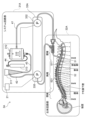
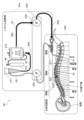
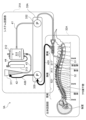
- FIGS. 19 to 22 are schematic diagrams illustrating the operation of the liquid circulation system according to this embodiment.
- the operation of the liquid circulation system 3 described with reference to FIGS. 19 to 22 is based on the control described above with reference to FIGS.
- the control unit 21, the first drive unit 23, and the second drive unit 24 are omitted in Figures 19 to 22.
- the operation described below will be described assuming that the operation starts from a primed state in which the tubes, reservoirs, and oxygenation mechanisms in the circuit are filled with artificial cerebrospinal fluid such as lactated Ringer's solution.
- the control unit 21 sends a control signal to the first drive unit 23 to control the operation of the first flow path switching unit 333 and connects the first tube 41 and the second tube 42.
- the control unit 21 also sends a control signal to the second drive unit 24 to control the operation of the second flow path switching unit 336 and connects the fourth tube 44 and the fifth tube 45.
- the control unit 21 sends a control signal to the first pump 332 to drive the first pump 332 in the second direction, and sends a control signal to the second pump 335 to drive the second pump 335 in the first direction.
- the liquid 91 (see FIG. 20) stored in the first liquid storage section 331 is returned to the oxygenation mechanism 312 through the first tube 41 and the second tube 42.
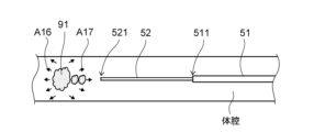
- the cerebrospinal fluid 92 in the body cavity is sucked into the outlet 511 of the drainage catheter 51.
- the cerebrospinal fluid 92 is supplied to the second liquid storage section 334 through the fourth tube 44 and the fifth tube 45 and stored therein.
- the control unit 21 sends a control signal to the first drive unit 23 to control the operation of the first flow path switching unit 333, and connects the first tube 41 and the second tube 42.
- the control unit 21 also sends a control signal to the second drive unit 24 to control the operation of the second flow path switching unit 336, and connects the fifth tube 45 and the sixth tube 46.
- the control unit 21 sends a control signal to the first pump 332 to drive the first pump 332 in the first direction, and sends a control signal to the second pump 335 to drive the second pump 335 in the second direction.
- the liquid 91 (i.e., the highly oxygenated solution) produced in the oxygenation mechanism 312 is supplied to and stored in the first liquid storage section 331 through the first tube 41 and the second tube 42.
- the cerebrospinal fluid 92 stored in the second liquid storage section 334 is supplied to and stored in the reservoir 311 through the fifth tube 45 and the sixth tube 46.
- the cerebrospinal fluid 92 stored in the reservoir 311 is supplied to the oxygenation mechanism 312 through the seventh tube 47.
- control unit 21 in the third step, sends a control signal to the first drive unit 23 to control the operation of the first flow path switching unit 333, and connects the second tube 42 and the third tube 43.
- the control unit 21 also sends a control signal to the second drive unit 24 to control the operation of the second flow path switching unit 336, and connects the fifth tube 45 and the sixth tube 46.
- the control unit 21 sends a control signal to the first pump 332 to drive the first pump 332 in the second direction, and sends a control signal to the second pump 335 to drive the second pump 335 in the first direction.
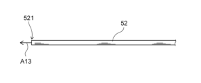
- the liquid 91 (i.e., the highly oxygenated solution) stored in the first liquid storage section 331 is supplied to the injection catheter 52 through the second tube 42 and the third tube 43. Then, for example, as shown by arrow A13 in FIG. 21, the liquid 91 is injected into the body cavity from the injection port 521 of the injection catheter 52. Meanwhile, as shown by arrow A47 in FIG. 21, the cerebrospinal fluid 92 stored in the reservoir 311 is returned to the second liquid storage section 334 through the fifth tube 45 and the sixth tube 46.
- the control unit 21 sends a control signal to the first drive unit 23 to control the operation of the first flow path switching unit 333, and connects the first tube 41 and the second tube 42.
- the control unit 21 also sends a control signal to the second drive unit 24 to control the operation of the second flow path switching unit 336, and connects the fifth tube 45 and the sixth tube 46.
- the control unit 21 sends a control signal to the first pump 332 to drive the first pump 332 in the first direction, and sends a control signal to the second pump 335 to drive the second pump 335 in the second direction.
- the liquid 91 (i.e., the highly oxygenated solution) produced in the oxygenation mechanism 312 is supplied to and stored in the first liquid storage section 331 through the first tube 41 and the second tube 42.
- the cerebrospinal fluid 92 stored in the second liquid storage section 334 is supplied to and stored in the reservoir 311 through the fifth tube 45 and the sixth tube 46.
- the cerebrospinal fluid 92 stored in the reservoir 311 is supplied to the oxygenation mechanism 312 through the seventh tube 47.
- the circuit for circulating the liquid is divided into a circuit including the injection catheter 52 and the discharge catheter 51 (i.e., the biological circuit section 32) and a circuit including the liquid supply lines (i.e., the first tube 41, the second tube 42, the third tube 43) connected to the injection catheter 52 and the liquid drainage lines (i.e., the fourth tube 44, the fifth tube 45, the sixth tube 46) connected to the discharge catheter 51 (i.e., the system circuit section 31).
- the first pump 332 provided on the liquid supply line for moving the liquid and the second pump 335 provided on the liquid drainage line for moving the liquid function as a shared pump in the biological circuit section 32 and the system circuit section 31.
- the system circuit section 31 can respond to the increase in the total volume of the liquid caused by the cavitation phenomenon and the decrease in the total volume of the liquid caused by evaporation while maintaining the condition on the biological side, and the increase or decrease in the amount of liquid in the biological circuit can be suppressed. This can suppress fluctuations in intracranial pressure.
- the control unit 21 also repeatedly drives the first pump 332, the second pump 335, the first flow path switching unit 333, and the second flow path switching unit 336 to switch the direction of the liquid flow so as to perform the operation shown in Figures 19 to 22.
- the injection of the liquid 91 and the discharge of the cerebrospinal fluid 92 are alternately repeated in equal amounts as long as the allowable fluctuation range of the intracranial pressure is not exceeded.
- the control unit 21 does not control the first flow path switching unit 333 to connect the second tube 42 and the third tube 43 and the second flow path switching unit 336 to connect the fourth tube 44 and the fifth tube 45 at the same time, so that the injection of the liquid 91 and the discharge of the cerebrospinal fluid 92 are not performed simultaneously, and the occurrence of a local steady flow of the liquid 91 injected into the body cavity from the injection port 521 of the injection catheter 52 toward the discharge port 511 of the discharge catheter 51 can be suppressed. Therefore, the liquid 91 injected into the body cavity flows toward the treatment area of the brain according to the injection direction and injection flow rate.
- the control unit 21 also controls the sum of the amount of fluid injected into the biological circuit unit 32 while the first pump 332 is operating continuously or intermittently in the third step and the amount of fluid discharged from the biological circuit unit 32 while the second pump 335 is operating continuously or intermittently in the first step, from the time of initial startup, to within a certain range.
- This makes it possible to keep fluctuations in the amount of cerebrospinal fluid from the time of initial startup of the first pump 332 and the second pump 335 within a certain range.
- This makes it possible to more reliably keep intracranial pressure from exceeding the allowable fluctuation range.
- This makes it possible to more reliably keep fluctuations in intracranial pressure within the allowable fluctuation range.
- the highly oxygenated solution can be efficiently delivered to the treatment area of the brain while suppressing fluctuations in intracranial pressure.
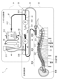
- FIG. 23 is a schematic diagram illustrating an overview of a liquid circulation system according to a first modified example of this embodiment.
- the liquid circulation system 3A according to this modification circulates a liquid by injecting the liquid into a body cavity and discharging it outside the body cavity.
- An example of the body cavity is a body cavity in which cerebrospinal fluid of a subject is present.
- a case where the liquid injected into the body cavity is a highly oxygenated solution is taken as an example.
- the liquid circulation system 3A includes a system circuit section 31A, a biological circuit section 32A, and a pump section 33A.
- the system circuit section 31A is a section that generates the highly oxygenated solution, adjusts the temperature, and adjusts the total volume of liquid in the circulation circuit, and has a control section 21, a reservoir 311, an oxygenation mechanism 312, and an oxygen supply source 313.
- the oxygenation mechanism 312 of this modified example is an example of the "liquid treatment device” and "oxygenation device” of the present invention.
- the biological circuit section 32A is a section that injects liquid into the body cavity and expels liquid from the body cavity, and has a drainage catheter 51 and an injection catheter 52.
- the drainage catheter 51 and the injection catheter 52 are connected to the pump section 33A and the system circuit section 31A, which includes the reservoir 311 and the oxygenation mechanism 312.
- the drainage catheter 51 and the injection catheter 52 are as described above with reference to Figures 1 to 17.
- the pump section 33A functions as a liquid delivery section shared by the system circuit section 31A and the biological circuit section 32A.
- the pump section 33A has a first pump 332 and a second pump 335.
- the first pump 332 and the second pump 335 can be a roller pump that delivers liquid in a liquid delivery tube by squeezing the tube with a roller, or a peristaltic pump that delivers liquid in a tube by squeezing the tube with multiple fingers.
- the oxygenation mechanism 312 is connected to the injection catheter 52 via the first tube 41.
- the oxygenation mechanism 312 is also connected to the reservoir 311 via the third tube 43.
- the oxygenation mechanism 312 is further connected to the oxygen supply source 313 via the fourth tube 44.
- the oxygenation mechanism 312 mixes the cerebrospinal fluid or lactate Ringer's solution or a mixture thereof supplied from the reservoir 311 via the third tube 43 with the oxygen supplied from the oxygen supply source 313 via the fourth tube 44 to generate oxygenated cerebrospinal fluid.
- the oxygenation mechanism 312 also has a heat exchanger that adjusts the temperature of the oxygenated cerebrospinal fluid.
- the oxygenation mechanism 312 supplies the oxygenated cerebrospinal fluid as a highly oxygenated solution to the injection catheter 52 via the first tube 41.
- a hollow fiber type artificial lung for adding oxygen to blood can be used as the oxygenation mechanism 312 in this modified example.
- the first pump 332 is provided on the path of the first tube 41.
- the first pump 332 operates based on a control signal sent from the control unit 21, and moves liquid from the oxygenation mechanism 312 toward the injection catheter 52.
- the first pump 332 When the first pump 332 is driven, it supplies the liquid (i.e., the highly oxygenated solution) produced in the oxygenation mechanism 312 through the first tube 41 to the injection catheter 52, and ultimately injects it into the body cavity.
- the liquid i.e., the highly oxygenated solution
- the reservoir 311 is connected to the drainage catheter 51 via the second tube 42.
- the reservoir 311 is also connected to the oxygenation mechanism 312 via the third tube 43.
- the reservoir 311 temporarily stores the cerebrospinal fluid supplied through the second tube 42.
- the reservoir 311 then supplies the stored cerebrospinal fluid to the oxygenation mechanism 312 through the third tube 43.
- the reservoir 311 has a structure in which the inside and outside are connected to each other, and gas contained in the stored cerebrospinal fluid can be released to the outside. In other words, the reservoir 311 functions as an air trap.
- the second pump 335 is provided on the second tube 42.
- the second pump 335 operates based on a control signal sent from the control unit 21, and moves liquid from the discharge catheter 51 toward the reservoir 311.
- the second pump 335 When the second pump 335 is driven, the second pump 335 supplies the liquid (i.e., cerebrospinal fluid) discharged from inside the body cavity to outside the body cavity through the discharge catheter 51 to the reservoir 311. As a result, the reservoir 311 stores the liquid (i.e., cerebrospinal fluid) discharged from inside the body cavity to outside the body cavity through the discharge catheter 51.
- the liquid i.e., cerebrospinal fluid
- FIGS. 24 and 25 are schematic diagrams illustrating the operation of the liquid circulation system according to this modified example.
- the operation of the liquid circulation system 3A described with reference to FIGS. 24 to 25 is based on the control described above with reference to FIGS.
- the control unit 21 is omitted in Figures 24 and 25.
- the operation described below will be described assuming that the operation starts from a primed state in which the tubes, reservoirs, and oxygenation mechanisms in the circuit are filled with artificial cerebrospinal fluid such as lactated Ringer's solution.
- the control unit 21 also alternately drives the first pump 332 and the second pump 335. Therefore, as long as the allowable fluctuation range of the intracranial pressure is not exceeded, the injection of the liquid 91 and the discharge of the cerebrospinal fluid 92 are alternately repeated in the same amount. Therefore, the injection of the liquid 91 and the discharge of the cerebrospinal fluid 92 are not performed simultaneously, and the occurrence of a local steady flow of the liquid 91 injected into the body cavity from the inlet 521 of the injection catheter 52 toward the outlet 511 of the discharge catheter 51 can be suppressed. Therefore, the liquid 91 injected into the body cavity flows toward the treatment area of the brain according to the injection direction and injection flow rate.
- the system circuit section 31B is the section that generates the highly oxygenated solution and adjusts the temperature, as well as adjusts the total volume of liquid in the circulation circuit, and includes the control section 21, a reservoir 311, an oxygenation mechanism 312, an oxygen supply source 313, and a heat exchanger 314.
- the biological circuit section 32B is a section that injects liquid into the body cavity and expels liquid from the body cavity, and includes a drainage catheter 51, an injection catheter 52, and a balloon catheter 54B.
- the drainage catheter 51 and the injection catheter 52 are connected to the pump section 33B and the system circuit section 31B, which includes the reservoir 311 and the oxygenation mechanism 312.
- the drainage catheter 51 and the injection catheter 52 are as described above with reference to Figures 1 to 17. Note that in the liquid circulation system 3B of this modified example, the injection catheter 52 is not disposed in the lumen 513 (see Figure 4) of the drainage catheter 51, and exists separately from the drainage catheter 51.
- the biological circuit section 32B further includes a balloon syringe 544, a balloon piston 545, and a fourth drive section 26.
- the balloon syringe 544 of this modified example is an example of a "balloon fluid storage section" of the present invention
- the balloon syringe 544 and the balloon piston 545 are an example of a "balloon drive section” of the present invention.
- the "balloon drive section" of the present invention includes the balloon syringe 544 and the balloon piston 545.
- the fourth drive section 26 of this modified example is an example of a "piston drive section" of the present invention.
- the balloon catheter 54B has a balloon 54 at its tip.
- the fourth drive unit 26 moves the balloon piston 545 in the insertion direction of the balloon syringe 544 based on a control signal sent from the control unit 21, the expansion fluid 93 stored in the balloon syringe 544 passes through the inner cavity of the balloon catheter 54B and flows toward the tip of the balloon catheter 54B.
- the expansion fluid 93 that has flowed toward the tip of the balloon catheter 54B is then supplied to the inside of the balloon 54 through a hole formed in the tip of the balloon catheter 54B.
- the expansion fluid 93 expands the balloon 54. In other words, the balloon 54 is inflated.
- the fourth drive unit 26 moves the balloon piston 545 in the direction of removing the balloon syringe 544 based on a control signal sent from the control unit 21, the expansion fluid 93 stored in the balloon 54 is sucked into and stored in the balloon syringe 544. This causes the expansion fluid 93 to be discharged from the balloon 54, causing the balloon 54 to contract.
- the balloon 54 is designed so that it does not strongly compress the subarachnoid space near the lumbar vertebrae into which the balloon catheter 54B is inserted, even at maximum expansion.
- the cross-sectional area of the spinal cavity is not perfectly circular. Furthermore, the spine in which the spinal cavity is located is gently S-shaped overall, and may be deformed due to aging, trauma, disease, etc. Therefore, it is desirable for the balloon 54 to be a compliant balloon made of an elastic material (stretchable material) such as rubber or elastomer, and whose volume changes depending on the amount of expansion fluid injected. A compliant balloon can deform to follow the shape of the spinal cavity.
- an elastic material such as rubber or elastomer
- the balloon 54 may have a structure in which, for example, multiple inflatable parts are provided in the axial direction, and the balloons are connected by a flexible material. This structure makes it possible to shorten the axial dimension (length) of each balloon and limit the outer diameter of each balloon when expanded to a certain value or less.
- each balloon may be independent, and the expansion fluid is injected from multiple positions separated in the axial direction, so that the balloon can be expanded uniformly without changing the total volume of the entire balloon when expanded, compared to when the balloon is composed of only one space, and the connection between the balloons becomes an inflection point, making it easier to follow the shape of the spinal cavity.
- the balloon 54 may also have a structure having multiple independent balloon catheters. Since each balloon catheter can be operated independently, the balloons can be moved and positioned to fill gaps according to the shape and cross-sectional area of the spinal cavity. By implementing this structure, the risk of strong compression of a part of the spinal cord due to the expansion of the balloon 54 is reduced, so that the load on the living body can be further reduced.
- the balloon 54 is not particularly limited in shape, etc., as long as it can follow the shape and cross-sectional area of the spinal cavity and does not strongly compress the spinal cord.
- the expansion fluid 93 may be a liquid or a gas.
- Examples of the expansion fluid 93 include saline, cerebrospinal fluid, and air.
- the expansion fluid 93 may be a fluid different from the liquid injected into the body cavity, or may be the same fluid as the liquid injected into the body cavity.
- the material of the balloon 54 may be, for example, an elastic material (i.e., a compliant material) made of elastomers such as silicone and natural rubber, or rubber.
- a compliant material made of elastomers such as silicone and natural rubber, or rubber.
- the material of the balloon 54 is not limited to these.
- Pump section 33B functions as a liquid delivery section shared by system circuit section 31B and biological circuit section 32B.
- Pump section 33B has a first pump 337 and a second pump 338.
- the first pump 337 of this modified example is an example of a "first liquid delivery section" of the present invention.
- the second pump 338 of this modified example is an example of a "second liquid delivery section" of the present invention.
- Examples of the first pump 337 and the second pump 338 include an infusion pump and a syringe pump.
- the oxygenation mechanism 312 is connected to the first pump 337 via the first tube 41.
- the first pump 337 is connected to the injection catheter 52.
- the oxygenation mechanism 312 is also connected to the reservoir 311 via the fifth tube 45.
- the oxygenation mechanism 312 is further connected to the oxygen supply source 313 via the sixth tube 46.
- the oxygenation mechanism 312 mixes the cerebrospinal fluid or lactate Ringer's solution or a mixture thereof supplied from the reservoir 311 via the fifth tube 45 with the oxygen supplied from the oxygen supply source 313 via the sixth tube 46 to generate oxygenated cerebrospinal fluid.
- the oxygenation mechanism 312 is also connected to the heat exchanger 314 via the seventh tube 47 and the eighth tube 48.
- the heat exchanger 314 adjusts the temperature of the oxygenated cerebrospinal fluid to about 37°C.
- the temperature adjustment by the heat exchanger is, for example, about 32°C to 40°C.
- the oxygenation mechanism 312 supplies oxygenated cerebrospinal fluid as a highly oxygenated solution to the infusion catheter 52 through the first tube 41 and the first pump 337.
- a hollow fiber membrane oxygenator for adding oxygen to blood can be used as the oxygenation mechanism 312 in this modified example.
- the first pump 337 is connected to the first tube 41 and the injection catheter 52, and is disposed between the first tube 41 and the injection catheter 52.
- the first tube 41 of this modified example is an example of the "liquid delivery line" of the present invention. That is, the first tube 41 is connected to the injection catheter 52 via the first pump 337.
- the first pump 337 operates based on a control signal sent from the control unit 21, and moves liquid from the oxygenation mechanism 312 toward the injection catheter 52.
- the first pump 337 When the first pump 337 is driven, the first pump 337 supplies the liquid (i.e., the highly oxygenated solution) produced in the oxygenation mechanism 312 through the first tube 41 to the injection catheter 52, and ultimately injects it into the body cavity.
- the liquid i.e., the highly oxygenated solution
- the reservoir 311 is connected to the second pump 338 via the fourth pipe 44.
- the reservoir 311 is also connected to the oxygenation mechanism 312 via the fifth pipe 45.
- the reservoir 311 temporarily stores the cerebrospinal fluid supplied through the fourth pipe 44.
- the reservoir 311 then supplies the stored cerebrospinal fluid to the oxygenation mechanism 312 through the fifth pipe 45.
- the reservoir 311 has a structure in which the inside and outside are connected to each other, and gas contained in the stored cerebrospinal fluid can be released to the outside. In other words, the reservoir 311 functions as an air trap.
- the second pump 338 is connected to the fourth tube 44 and the discharge catheter 51, and is disposed between the fourth tube 44 and the discharge catheter 51.
- the fourth tube 44 of this modified example is an example of the "drainage line" of the present invention. That is, the fourth tube 44 is connected to the discharge catheter 51 via the second pump 338.
- the second pump 338 operates based on a control signal sent from the control unit 21, and moves liquid from the discharge catheter 51 toward the reservoir 311.
- the second pump 338 When the second pump 338 is driven, the second pump 338 supplies the liquid (i.e., cerebrospinal fluid) discharged from inside the body cavity to outside the body cavity through the discharge catheter 51 to the reservoir 311 through the fourth tube 44. As a result, the reservoir 311 stores the liquid (i.e., cerebrospinal fluid) discharged from inside the body cavity to outside the body cavity through the discharge catheter 51.
- the liquid i.e., cerebrospinal fluid
- the liquid circulation system 3B may have a balloon catheter 54B with a balloon 54 at its tip.
- the control unit 21 can suppress fluctuations in the volume of the body cavity as a closed space by controlling the operation of the first pump 337 and the operation of the second pump 338 and the expansion and contraction of the balloon 54 arranged in the body cavity. Therefore, the body cavity can change its volume in a high compliance region and deform in accordance with the amount of liquid that has decreased or increased in the body cavity. This suppresses fluctuations in intracranial pressure.
- control unit 21 controls each of the first pump 337 and the second pump 338 and further controls the expansion and contraction of the balloon 54, thereby more appropriately setting the timing and speed of the injection of the liquid 91 and the contraction of the balloon 54, as well as the timing and speed of the discharge of the liquid 91 and the expansion of the balloon 54. This further suppresses fluctuations in intracranial pressure.
- FIG. 27 is a schematic diagram showing a modified example of the medical device of this embodiment.
- the components of the medical device 5B shown in Figure 27 are similar to the components of the medical device 5 described above with reference to Figures 2 to 4, duplicated explanations will be omitted as appropriate, and the following explanation will focus on the differences.
- the medical device 5B shown in FIG. 27 has a drainage catheter 51, an injection catheter 52B, and a balloon 54, and is used, for example, in the liquid circulation system 3B described above with reference to FIG. 26.
- the balloon 54 is provided at the tip of the injection catheter 52B.
- the injection catheter 52B has a balloon 54 at its tip.
- the drainage catheter 51 is as described above with reference to FIGS. 2 to 4.
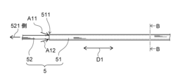
- the injection catheter 52B is disposed in the lumen 513 of the discharge catheter 51 and is not connected to the discharge catheter 51. Therefore, the injection catheter 52B can move in the lumen 513 of the discharge catheter 51 along the longitudinal direction D1 of the discharge catheter 51. Since the tip of the discharge catheter 51 opens as the discharge port 511, as shown in FIG. 27, the tip of the injection catheter 52B (i.e., the portion where the balloon 54 is provided) can pass through the discharge port 511 of the discharge catheter 51.
- the medical device 5B has a structure in which only the injection catheter 52B and the balloon 54 are integrally formed, and are not connected to the discharge catheter 51. With this structure, it is possible to change the positions of the injection catheter and the discharge catheter, and therefore it is possible to position the injection catheter according to the shape of the patient's spinal cavity.
- the balloon 54 in this embodiment is not limited to being formed integrally with the injection catheter.
- the balloon 54 may be formed separately from the injection catheter and provided at the tip of the balloon catheter 54B.
- the distance in the longitudinal direction D1 between the tip of the discharge catheter 51 and the tip of the injection catheter 52B exposed from the discharge port 511 of the discharge catheter 51 is preferably, for example, 0 mm or more and 300 mm or less.
- the cross-sectional area of a typical spinal cavity is about 6.7 mm 2 to 16.7 mm 2 and that the discharge catheter 51 is disposed in the spinal cavity separately from the balloon 54
- the cross-sectional area of the balloon 54 is preferably about half that area, for example, about 3.3 mm 2 to 8.3 mm 2.
- the length of the balloon 54 along the longitudinal direction D1 is, for example, about 1 mm to 300 mm, preferably 36 mm to 200 mm.
- the balloon 54 and the discharge port 511 at the tip of the discharge catheter 51 come into contact with each other and can function without interfering with each other.
- the expansion fluid supplied from the base end of the injection catheter 52B passes through the lumen 542B formed inside the injection catheter 52B and flows toward the tip of the injection catheter 52B. Then, as shown by arrow A4 in FIG. 27, the expansion fluid flowing toward the tip of the injection catheter 52B passes through a hole 541B formed at the tip of the injection catheter 52B and is supplied to the inside of the balloon 54. As a result, the expansion fluid expands the balloon 54. In other words, the balloon 54 expands. On the other hand, when the expansion fluid is discharged from the balloon 54, the balloon 54 contracts.
- the drainage catheter 51 draws cerebrospinal fluid present in the subarachnoid space near the lumbar vertebrae into space 53 through drainage port 511. Also, as shown by arrow A10 in FIG. 27, the drainage catheter 51 draws cerebrospinal fluid present in the subarachnoid space near the lumbar vertebrae into space 53 through multiple holes 512. Then, as shown by arrow A6 in FIG. 27, the drainage catheter 51 drains cerebrospinal fluid out of the subject's body cavity through space 53.
- injection catheter 52B injects liquid from injection port 521 through lumen 523 of injection catheter 52B into cerebrospinal fluid present in the subarachnoid space.
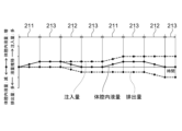
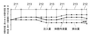
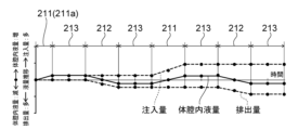
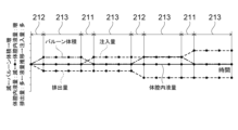
- FIG. 28 is a graph showing the relationship between the injection amount, the discharge amount, the balloon volume, and the amount of fluid in the body cavity under the control of the medical system according to the second modification of this embodiment.
- the case where the medical device 5B described above with reference to FIG. 27 is used will be taken as an example.
- the horizontal axis of the graph shown in FIG. 28 represents time.
- the vertical axis of the graph shown in FIG. 28 represents the change in the volume of fluid.
- the "injection volume” shown in FIG. 28 represents the cumulative volume of fluid 91 injected into the body cavity from the start of control execution.
- the “discharge volume” shown in FIG. 28 represents the cumulative volume of cerebrospinal fluid discharged outside the body cavity from the start of control execution.
- the "volume of fluid in the body cavity” shown in FIG. 28 represents the change in the volume of cerebrospinal fluid present in the body cavity at the start of control execution.
- the vertical axis of the graph shown in FIG. 28 represents the change in the volume of the balloon 54.
- control unit 21 sets a second period 212 during which the liquid 91 is not injected into the body cavity, the liquid 91 is discharged from the body cavity, and the balloon 54 placed in the body cavity is expanded, and a first period 211 during which the liquid 91 is injected into the body cavity, the liquid 91 is not discharged from the body cavity, and the balloon 54 is deflated.
- the drainage catheter 51 draws cerebrospinal fluid 92 (including liquid 91) present in the subarachnoid space near the lumbar vertebrae into space 53 through multiple holes 512, and drains it to the outside of the subject's body cavity through space 53.
- the expansion fluid 93 is supplied from the base end of the medical device 5B, passes through the lumen 542B, and is supplied to the inside of the balloon 54 through hole 541B. This causes the balloon 54 to expand.
- control unit 21 can suppress fluctuations in the volume of the body cavity as a closed space during the second period 212 in which cerebrospinal fluid 92 (including liquid 91) is discharged from the body cavity. Therefore, the volume of the body cavity can fluctuate in the high compliance region, and the body cavity can deform in response to the reduced amount of liquid in the body cavity. Therefore, fluctuations in intracranial pressure during the second period 212 are suppressed.
- the amount of liquid reduced in the body cavity i.e., the volume
- the amount by which the balloon 54 expands in the body cavity i.e., the volume. Therefore, the volume of the body cavity does not substantially change during the second period 212. This more reliably suppresses fluctuations in intracranial pressure during the second period 212.
- the injection catheter 52B injects the liquid 91 supplied from the base end of the injection catheter 52B through the lumen 523 into the cerebrospinal fluid present in the subarachnoid space from the injection port 521. Also, during the first period 211, the expansion fluid 93 inside the balloon 54 passes through the hole 541B and the lumen 542B and is discharged to the outside of the balloon 54. This causes the balloon 54 to contract.
- control unit 21 can suppress fluctuations in the volume of the body cavity as a closed space during the first period 211 in which the liquid 91 is injected into the body cavity. Therefore, the volume of the body cavity can be changed in a high compliance region, and the body cavity can deform in response to the increased amount of liquid in the body cavity. Therefore, fluctuations in intracranial pressure during the first period 211 are suppressed.
- the control unit 21 simultaneously injects the liquid 91 and deflates the balloon 54 during the first period 211. Furthermore, the control unit 21 sets the amount of deflation of the balloon 54 (i.e., the amount of expansion fluid 93 discharged from the balloon 54) during the first period 211 to be substantially the same as the amount of liquid 91 injected.
- the amount of liquid (i.e., volume) increased within the body cavity is substantially the same as the amount (i.e., volume) by which the balloon 54 is deflated within the body cavity. Therefore, the volume of the body cavity does not substantially change during the first period 211. This more reliably suppresses fluctuations in intracranial pressure during the first period 211.
- the control unit 21 further sets a third period 213, during which the liquid 91 is not injected into the body cavity and the liquid 91 is not discharged from the body cavity, between the second period 212 and the first period 211 and between the first period 211 and the second period 212. That is, during the third period 213, the injection of the liquid 91 into the body cavity and the discharge of the liquid 91 from the body cavity are stopped simultaneously.
- the control unit 21 repeats the second period 212, the third period 213, the first period 211, and the third period 213 in this order.
- the third period as shown by the arrows A24 and A25 in FIG.
- the duration of the third period 213 is preferably until the flow caused by the previous injection or discharge has disappeared, and specifically, is preferably 1 second or more.
- the control unit 21 executes control to maintain the balloon 54 in an expanded state during the third period 213 between the second period 212 and the first period 211.
- the control unit 21 maintains a state in which the expansion fluid 93 is supplied to the inside of the balloon 54 during the third period 213 between the second period 212 and the first period 211, thereby maintaining the balloon 54 in an expanded state.
- control unit 21 executes control to maintain the balloon 54 in a contracted state during a third period between the first and second periods.
- the control unit 21 maintains the balloon 54 in a contracted state by maintaining a state in which the expansion fluid 93 is discharged outside the balloon 54 during the third period between the first and second periods.
- the amount of liquid (i.e., volume) that increases or decreases in the body cavity is substantially the same as the amount of the balloon 54 that increases or decreases in the body cavity. Therefore, the volume of the body cavity does not change substantially. This suppresses fluctuations in intracranial pressure. Furthermore, since the volume of the body cavity does not change substantially, the body cavity can change its volume in a high compliance region regardless of the amount of liquid 91 injected, and can deform in response to the amount of liquid that increases or decreases in the body cavity. Therefore, even if the balance of the amount of liquid is somewhat lost, the body cavity can respond by compliance. Furthermore, since the volume of the body cavity does not change substantially regardless of the amount of liquid 91 injected, the amount of liquid 91 injected can be increased as long as there is space for the balloon 54 to expand.
- the amount of fluid injected into the balloon and the amount of fluid discharged from the balloon are limited to "(total of n balloon injections) - (total of n-1 balloon discharges) ⁇ nth discharge.”
- the amount of fluid discharged at one time is not particularly limited as long as it does not exceed the volume of the spinal cavity, and is, for example, about 1 mL to 30 mL.
- the amount of fluid injected at one time is about 1 mL to 30 mL, and more preferably about 3 to 10 mL considering the cross-sectional area of the balloon 54 and the length that can be placed along the longitudinal direction D1.
- control unit 21 further sets a third period 213 between the second period 212 and the first period 211 and between the first period 211 and the second period 212, during which the liquid 91 is not injected into the body cavity and the liquid 91 is not discharged from the body cavity. Therefore, the diffusion of oxygen and the like contained in the liquid 91 progresses further depending on the length of the third period. This allows the liquid to be delivered to the treatment area of the brain more efficiently.
Landscapes
- Health & Medical Sciences (AREA)
- Heart & Thoracic Surgery (AREA)
- Engineering & Computer Science (AREA)
- Life Sciences & Earth Sciences (AREA)
- Biomedical Technology (AREA)
- Public Health (AREA)
- General Health & Medical Sciences (AREA)
- Anesthesiology (AREA)
- Veterinary Medicine (AREA)
- Hematology (AREA)
- Animal Behavior & Ethology (AREA)
- Child & Adolescent Psychology (AREA)
- Pulmonology (AREA)
- Biophysics (AREA)
- Neurology (AREA)
- Ophthalmology & Optometry (AREA)
- Otolaryngology (AREA)
- Vascular Medicine (AREA)
- External Artificial Organs (AREA)
Abstract
Description
本発明は、脳疾患の治療に用いられる医療システムおよび液体循環システムに関する。 The present invention relates to a medical system and a fluid circulation system used to treat brain diseases.
脳疾患として例えば脳梗塞が発症すると、脳細胞に酸素を供給する血流が遮断され、脳細胞にダメージが発生するおそれがある。したがって、脳梗塞が発症した場合には、血流の早期再灌流が必要である。脳梗塞の治療の1つとして、酸素化した脳脊髄液などの高酸素化溶液を患者の脳脊髄液が存在する体腔内に注入し、酸素が欠乏している脳細胞に酸素を直接供給することが提案されている。 When a brain disease such as cerebral infarction occurs, the blood flow that supplies oxygen to brain cells is blocked, which can cause damage to the brain cells. Therefore, when a cerebral infarction occurs, early reperfusion of blood flow is necessary. As one treatment for cerebral infarction, it has been proposed to inject a highly oxygenated solution such as oxygenated cerebrospinal fluid into the body cavity where the cerebrospinal fluid is present in the patient, thereby directly supplying oxygen to oxygen-deficient brain cells.
特許文献1には、1つのルーメンで液体の生体への注入及び生体からの吸引を行うことのできるカテーテルシステムが開示されている。特許文献1に記載されたカテーテルシステムは、カテーテルと、管本体のルーメンを介して注入口に流体を供給する注入駆動部と、吸引口から管本体のルーメンを介して流体を吸引する吸引駆動部と、頭蓋内圧の状態を検出する検出部と、注入駆動部及び吸引駆動部を制御する制御部と、を有する。カテーテルの吸引口は、カテーテルの注入口が開状態の際に閉状態である。また、カテーテルの注入口は、カテーテルの吸引口が開状態の際に閉状態である。そして、制御部は、検出部で検出された頭蓋内圧の状態が一定の範囲となるように、注入駆動部と吸引駆動部とを交互に動作させる。
ここで、脳疾患の治療を目的として高酸素化溶液などの液体が体腔内に注入される場合、頭蓋内圧を一定範囲に保つ必要がある。頭蓋内圧の正常な範囲は、5mmHg以上、15mmHg以下程度である。頭蓋内から脊髄腔内までの圧力が変動すると、脳に障害を与えるおそれがある。例えば、頭蓋内圧が20mmHg以上に上昇すると、頭蓋内圧亢進症(すなわち脳組織が負荷を受けることで発症する様々な症状)が発生するおそれがある。一方で、頭蓋内圧が5mmHg以下に低下すると、低髄液圧症候群(すなわち脳組織の位置を保てなくなることで発症する様々な症状)が発生するおそれがある。 Here, when a liquid such as a highly oxygenated solution is injected into a body cavity for the purpose of treating a brain disease, it is necessary to maintain intracranial pressure within a certain range. The normal range for intracranial pressure is approximately 5 mmHg or more and 15 mmHg or less. Fluctuations in pressure from inside the skull to inside the spinal cavity can cause brain damage. For example, if intracranial pressure rises to 20 mmHg or more, there is a risk of intracranial hypertension (i.e., various symptoms that develop when brain tissue is placed under stress). On the other hand, if intracranial pressure falls to 5 mmHg or less, there is a risk of low cerebrospinal fluid pressure syndrome (i.e., various symptoms that develop when brain tissue cannot maintain its position).
脳脊髄液が存在する体腔(例えばクモ膜下腔および脳室)は、ほぼ閉鎖空間である。そのため、頭蓋内圧を一定範囲に保つためには、体腔内の脳脊髄液の量を一定範囲に保つ必要がある。体腔内の脳脊髄液の量を一定範囲に保つためには、体腔内に注入した液体の量と同じ量の脳脊髄液を速やかに排出することが求められる。 Body cavities in which cerebrospinal fluid exists (for example, the subarachnoid space and ventricles) are almost entirely closed spaces. Therefore, in order to maintain intracranial pressure within a constant range, it is necessary to maintain the amount of cerebrospinal fluid within the body cavity within a constant range. In order to maintain the amount of cerebrospinal fluid within a body cavity within a constant range, it is necessary to quickly expel an amount of cerebrospinal fluid equal to the amount of fluid injected into the body cavity.
しかし、例えば腰椎付近からクモ膜下腔に挿入された注入用カテーテルおよび排出用カテーテルを介してポンプにより液体を循環させて液体を体腔内に注入する場合、注入のタイミングおよび排出のタイミングによっては、注入用カテーテルの注入口から体腔内に注入された液体が排出用カテーテルの排出口に向かう流れ(すなわち局所定常流)が形成される。これにより、注入用カテーテルの注入口から脳の治療領域に向かう液体の流れがわずかとなり、脳の治療領域に液体を効率的に送達できないという問題がある。 However, when injecting liquid into a body cavity by circulating the liquid with a pump through an injection catheter and a drainage catheter inserted into the subarachnoid space near the lumbar spine, depending on the timing of injection and drainage, a flow of the liquid injected into the body cavity from the injection catheter's inlet toward the drainage catheter's outlet (i.e., a local steady flow) can form. This results in only a small flow of liquid from the injection catheter's inlet toward the treatment area of the brain, posing the problem that the liquid cannot be delivered efficiently to the treatment area of the brain.
この問題を解決するために、注入用カテーテルの注入口を脳の付近に配置し、排出用カテーテルの排出口を腰椎付近に配置することで、注入口と排出口との間の距離を十分に取り、局所定常流の影響を極力抑えることが考えられる。しかしながら、脳の付近までカテーテルを挿入しようとした場合、周囲に脊髄のような神経組織が走行しているとともに湾曲しているクモ膜下腔にカテーテルを長距離に渡って挿入することとなる。このようなカテーテルのクモ膜下腔深部への挿入には神経組織へダメージを与えるリスクが伴うため、カテーテルの挿入長は可能な限り短くすることが望ましい。 To solve this problem, it is conceivable that the inlet of the injection catheter could be placed near the brain, and the outlet of the drainage catheter placed near the lumbar vertebrae, thereby providing a sufficient distance between the injection and drainage ports and minimizing the effects of local steady flow. However, when attempting to insert a catheter close to the brain, the catheter would have to be inserted a long distance into the curved subarachnoid space, which is surrounded by nerve tissue such as the spinal cord. Inserting such a catheter deep into the subarachnoid space carries the risk of damaging the nerve tissue, so it is desirable to insert the catheter as short as possible.
また、例えば腰椎付近からクモ膜下腔に挿入された注入用カテーテルおよび排出用カテーテルを介してポンプにより液体を循環させて液体を体腔内に注入する場合、体腔内の脳脊髄液の量を一定範囲に保つためには、注入用カテーテルおよび排出用カテーテルのそれぞれの内腔の断面積、内腔の表面性状による流体抵抗、および長さなどのパラメータをコントロールし、注入量および排出量を一定にする必要がある。しかし、カテーテルの製造時のばらつき、および使用時のカテーテルの内腔の断面形状の変形などにより、前述したパラメータにばらつきが生ずる。そのため、注入量および排出量を一定にすることは困難である。 In addition, for example, when injecting a liquid into a body cavity by circulating the liquid with a pump through an injection catheter and a drainage catheter inserted into the subarachnoid space near the lumbar spine, in order to keep the amount of cerebrospinal fluid in the body cavity within a certain range, it is necessary to control parameters such as the cross-sectional area of the lumen of each of the injection catheter and the drainage catheter, the fluid resistance due to the surface properties of the lumen, and the length, and to keep the injection amount and drainage amount constant. However, variations in the aforementioned parameters occur due to variations in the manufacturing of the catheters and deformation of the cross-sectional shape of the catheter lumen during use. For this reason, it is difficult to keep the injection amount and drainage amount constant.
また、液体の循環回路は、感染防止のために閉鎖系であることが望ましい。しかし、液体の循環回路が閉鎖系である場合、キャビテーション現象により気泡が循環回路内で発生することにより液体の全体容量が治療初期の容量よりも増加したり、脳脊髄液を酸素化する過程において水分が蒸発により失われることにより液体の全体容量が治療初期の容量よりも減少したりするおそれがある。閉鎖系の循環回路において液体の全体容量が増加したり減少したりすると、頭蓋内圧を一定範囲に保つことができないおそれがある。 In addition, it is desirable for the liquid circulation circuit to be a closed system to prevent infection. However, if the liquid circulation circuit is a closed system, there is a risk that the total volume of the liquid will increase compared to the volume at the beginning of treatment due to bubbles being generated within the circulation circuit due to the cavitation phenomenon, or that the total volume of the liquid will decrease compared to the volume at the beginning of treatment due to water being lost through evaporation during the process of oxygenating the cerebrospinal fluid. If the total volume of the liquid increases or decreases in a closed circulation circuit, there is a risk that intracranial pressure cannot be maintained within a constant range.
本発明は、前記事情に鑑みてなされたものであり、頭蓋内圧の変動を抑えつつ脳の治療領域に液体を効率的に送達できる医療システムおよび液体循環システムを提供することを目的とする。 The present invention was made in consideration of the above circumstances, and aims to provide a medical system and a liquid circulation system that can efficiently deliver liquid to treatment areas of the brain while suppressing fluctuations in intracranial pressure.
本発明は、(1)対象者の脳脊髄液が存在する体腔内に液体を注入し、前記体腔内に存在する前記液体を前記体腔内から排出する医療システムであって、前記体腔内に前記液体を注入し、かつ、前記液体を前記体腔内から排出しない第1期間と、前記体腔内に前記液体を注入せず、かつ、前記液体を前記体腔内から排出する第2期間と、を設定し、前記第1期間と前記第2期間とを交互に繰り返し、前記第1期間における前記液体の注入量を前記第2期間における前記液体の排出量と実質的に同じに設定する制御を実行する制御部を備えたことを特徴とする医療システムである。 The present invention is (1) a medical system for injecting a liquid into a body cavity in which cerebrospinal fluid of a subject is present and discharging the liquid present in the body cavity from the body cavity, the medical system being characterized in that it has a control unit that executes control to set a first period during which the liquid is injected into the body cavity and is not discharged from the body cavity, and a second period during which the liquid is not injected into the body cavity and is discharged from the body cavity, alternately repeating the first period and the second period, and setting the amount of the liquid injected in the first period to be substantially the same as the amount of the liquid discharged in the second period.
上記(1)の医療システムによれば、制御部は、第1期間において、体腔内に液体を注入し、かつ、液体を体腔内から排出しない。また、制御部は、第2期間において、体腔内に液体を注入せず、かつ、液体を体腔内から排出する。そして、制御部は、第1期間と第2期間とを交互に繰り返し、液体の注入量を液体の排出量を実質的に同じにする。これにより、頭蓋内圧の許容変動範囲を超えない限りにおいて、液体の注入および液体の排出が同量で交互に繰り返される。そのため、液体の注入および液体の排出が同時に行われることはなく、注入口から体腔内に注入された液体が排出口に向かう局所定常流の発生を抑えることができる。そのため、体腔内に注入された液体は、注入方向および注入流速に従い脳の治療領域に向かって流れる。また、体腔内に注入された液体と体腔内の脳脊髄液との間の抵抗により生ずる乱流により、液体および脳脊髄液が撹拌される。さらに、液体に含まれる酸素等の濃度差による拡散が進行する。これにより、脳の治療領域に液体を効率的に送達できる。また、液体の注入量が液体の排出量と実質的に同じであるため、体腔内の脳脊髄液の量を一定範囲に保つことができる。これにより、頭蓋内圧の大幅な変動を抑えることができる。 According to the medical system of (1) above, the control unit injects liquid into the body cavity during the first period, and does not discharge the liquid from the body cavity. Also, the control unit does not inject liquid into the body cavity during the second period, and discharges the liquid from the body cavity. The control unit alternates between the first period and the second period, and makes the amount of liquid injected and the amount of liquid discharged substantially the same. As a result, the injection and discharge of liquid are alternately repeated in the same amount, as long as the allowable fluctuation range of the intracranial pressure is not exceeded. Therefore, the injection and discharge of liquid are not performed simultaneously, and the occurrence of a local steady flow of the liquid injected from the injection port into the body cavity toward the discharge port can be suppressed. Therefore, the liquid injected into the body cavity flows toward the treatment area of the brain according to the injection direction and injection flow rate. Also, the liquid and the cerebrospinal fluid are stirred by turbulence caused by the resistance between the liquid injected into the body cavity and the cerebrospinal fluid in the body cavity. Furthermore, diffusion due to the concentration difference of oxygen and the like contained in the liquid progresses. As a result, the liquid can be efficiently delivered to the treatment area of the brain. In addition, because the amount of fluid injected is essentially the same as the amount of fluid removed, the amount of cerebrospinal fluid in the cavity can be kept within a constant range. This helps prevent large fluctuations in intracranial pressure.
(2)上記(1)の医療システムにおいて、前記第1期間の開始から前記第2期間の終了までの周期が、実質的に一定であることが好ましい。
上記(2)の医療システムによれば、液体および脳脊髄液の撹拌と、液体に含まれる酸素等の濃度差による拡散と、の少なくともいずれかが、安定的に進行する。これにより、脳の治療領域に液体を効率的に送達できる。また、体腔内の脳脊髄液の量を一定範囲に安定的に保つことができる。これにより、頭蓋内圧の変動を抑えることができる。
(2) In the medical system of (1) above, it is preferable that a period from the start of the first period to the end of the second period is substantially constant.
According to the medical system of (2) above, at least one of the stirring of the liquid and the cerebrospinal fluid and the diffusion due to the concentration difference of oxygen and the like contained in the liquid proceeds stably. This allows the liquid to be efficiently delivered to the treatment area of the brain. Also, the amount of cerebrospinal fluid in the body cavity can be stably maintained within a certain range. This allows the fluctuation of intracranial pressure to be suppressed.
(3)上記(1)または(2)の医療システムにおいて、前記制御部は、前記体腔内に前記液体を注入せず、かつ、前記液体を前記体腔内から排出しない第3期間を、前記第1期間と前記第2期間との間にさらに設定することが好ましい。
上記(3)の医療システムによれば、液体に含まれる酸素等の濃度差による拡散が、第3期間の長さに応じてより一層進行する。これにより、脳の治療領域に液体をより一層効率的に送達できる。
(3) In the medical system of (1) or (2) above, it is preferable that the control unit further sets a third period between the first period and the second period, during which the liquid is not injected into the body cavity and the liquid is not discharged from the body cavity.
According to the medical system of (3) above, diffusion due to the difference in concentration of oxygen and the like contained in the liquid progresses more according to the length of the third period, thereby enabling the liquid to be delivered to the treatment area of the brain more efficiently.
(4)上記(3)の医療システムにおいて、前記第3期間の時間が、前記第1期間の時間よりも長いことが好ましい。
上記(4)の医療システムによれば、液体に含まれる酸素等の濃度差による拡散が進行する時間が、液体の注入時間よりも長い。これにより、脳の治療領域に液体をより一層効率的に送達できる。
(4) In the medical system of (3) above, it is preferable that the third period is longer than the first period.
According to the medical system of (4) above, the time during which diffusion due to the concentration difference of oxygen and the like contained in the liquid progresses is longer than the time during which the liquid is injected, which allows the liquid to be delivered to the treatment area of the brain more efficiently.
(5)上記(3)または(4)の医療システムにおいて、前記第3期間の時間が、1秒以上であることが好ましい。
上記(5)の医療システムによれば、液体に含まれる酸素等の濃度差による拡散が進行する時間を確保できる。これにより、脳の治療領域に液体を効率的に送達できる。
(5) In the medical system of (3) or (4) above, it is preferable that the third period of time is 1 second or longer.
According to the medical system of (5) above, time can be secured for diffusion due to the concentration difference of oxygen and the like contained in the liquid to proceed, thereby enabling the liquid to be efficiently delivered to the treatment area of the brain.
(6)上記(3)~(6)のいずれかの医療システムにおいて、前記制御部は、前記第3期間を前記第2期間と前記第1期間との間にさらに設定し、前記第1期間と前記第2期間との間に設定された前記第3期間の第1時間が、前記第2期間と前記第1期間との間に設定された前記第3期間の第2時間よりも長いことが好ましい。 (6) In any of the medical systems (3) to (6) above, it is preferable that the control unit further sets the third period between the second period and the first period, and that the first time of the third period set between the first period and the second period is longer than the second time of the third period set between the second period and the first period.
上記(6)の医療システムによれば、液体の注入と液体の排出との間に設けられた停止期間(すなわち第3期間)の第1時間が、液体の排出と液体の注入との間に設けられた停止期間(すなわち第3期間)の第2時間よりも長い。そのため、注入口から体腔内に注入された液体が排出口に向かう局所定常流の発生をより確実に抑え、液体に含まれる酸素等の濃度差による拡散が進行する時間を確実に確保できる。これにより、脳の治療領域に液体をより一層効率的に送達できる。 According to the medical system of (6) above, the first time of the pause period (i.e., the third period) between the injection and discharge of the liquid is longer than the second time of the pause period (i.e., the third period) between the discharge and injection of the liquid. This more reliably prevents the occurrence of a local steady flow of the liquid injected from the injection port into the body cavity toward the discharge port, and more reliably ensures time for diffusion due to concentration differences in oxygen and other substances contained in the liquid to proceed. This allows the liquid to be delivered to the treatment area of the brain more efficiently.
(7)上記(1)~(6)のいずれかの医療システムにおいて、前記第2期間における前記液体の排出速度は、前記第1期間における前記液体の注入速度よりも遅いことが好ましい。
上記(7)の医療システムによれば、第2期間における液体の排出速度が第1期間における液体の注入速度よりも遅いため、注入口から体腔内に注入された液体が排出口側に向かう速度を抑えることができ、注入口から体腔内に注入された直後の液体が脳の方向に拡散する時間を確保することが可能となる。これにより、脳の治療領域に液体を効率的に送達できる。
(7) In any of the medical systems described above in (1) to (6), it is preferable that a discharge rate of the liquid during the second period is slower than a supply rate of the liquid during the first period.
According to the medical system of (7) above, since the discharge speed of the liquid in the second period is slower than the injection speed of the liquid in the first period, the speed at which the liquid injected from the injection port into the body cavity moves toward the outlet can be suppressed, and it is possible to ensure that the liquid has enough time to diffuse toward the brain immediately after being injected from the injection port into the body cavity, thereby enabling the liquid to be efficiently delivered to the treatment area of the brain.
(8)上記(1)~(7)のいずれかの医療システムにおいて、前記制御部は、前記第1期間における前記注入量および前記第2期間における前記排出量よりも少ない量の前記液体を注入または排出する第0期間を初回に設定し、前記第1期間および前記第2期間のうち前記第0期間とは前記液体の移動方向が異なる期間を前記第0期間の次に開始することが好ましい。
上記(8)の医療システムによれば、初回の第0期間におけるクモ膜下腔内の容量変化を少なくすることで、第0期間以降の第1期間および第2期間におけるクモ膜下腔内の容量変化は、元の容量を挟んだ範囲で変動する。そのため、許容変動範囲を超えることを抑えることができる。これにより、頭蓋内圧の変動を許容変動範囲内に抑えることができる。
(8) In any of the medical systems (1) to (7) above, it is preferable that the control unit initially sets a 0th period in which the liquid is injected or discharged in an amount smaller than the injection amount in the first period and the discharge amount in the second period, and starts a period of the first period or the second period in which the liquid moves in a different direction from the 0th period after the 0th period.
According to the medical system of (8) above, by reducing the volume change in the subarachnoid space in the initial zeroth period, the volume change in the subarachnoid space in the first and second periods after the zeroth period varies within a range including the original volume. Therefore, it is possible to prevent the volume change from exceeding the allowable variation range. This makes it possible to keep the variation in intracranial pressure within the allowable variation range.
(9)上記(8)の医療システムにおいて、前記第0期間における注入量が、前記第1期間における前記注入量の実質的に半分であり、前記第0期間における排出量が、前記第2期間における前記排出量の実質的に半分であることが好ましい。
上記(9)の医療システムによれば、頭蓋内圧が初回の第1期間における液体の注入により許容変動範囲を超えることをより確実に抑えることができる。これにより、頭蓋内圧の変動をより確実に許容変動範囲内に抑えることができる。
(9) In the medical system of (8) above, it is preferable that the injection amount during the zero time period is substantially half of the injection amount during the first time period, and the discharge amount during the zero time period is substantially half of the discharge amount during the second time period.
According to the medical system of (9) above, it is possible to more reliably prevent intracranial pressure from exceeding the allowable fluctuation range due to the injection of liquid in the initial first period, thereby more reliably suppressing fluctuations in intracranial pressure within the allowable fluctuation range.
(10)上記(1)~(9)のいずれかの医療システムにおいて、前記制御部は、前記制御の終了時に、前記体腔内に前記液体を注入することにより前記制御の実行開始時において前記体腔内に存在していた前記脳脊髄液の量に近づける、または、前記液体を前記体腔内から排出することにより前記制御の実行開始時において前記体腔内に存在していた前記脳脊髄液の量に近づける制御を実行することが好ましい。 (10) In any of the medical systems (1) to (9) above, it is preferable that the control unit, at the end of the control, executes control to inject the liquid into the body cavity to bring the amount of cerebrospinal fluid close to the amount present in the body cavity at the start of execution of the control, or to discharge the liquid from the body cavity to bring the amount of cerebrospinal fluid close to the amount present in the body cavity at the start of execution of the control.
上記(10)の医療システムによれば、医療システムの制御の終了時における脳脊髄液の量を、医療システムの制御の実行開始時において体腔内に存在していた脳脊髄液の量と実質的に同じに設定することができる。そのため、医療システムの制御の終了時における頭蓋内圧を、医療システムの制御の実行開始時における頭蓋内圧と実質的に同じに設定することができる。これにより、医療システムの制御の終了時と医療システムの制御の実行開始時との間において、頭蓋内圧の変動を抑えることができる。 According to the medical system of (10) above, the amount of cerebrospinal fluid at the end of control of the medical system can be set to be substantially the same as the amount of cerebrospinal fluid present in the body cavity at the start of execution of control of the medical system. Therefore, the intracranial pressure at the end of control of the medical system can be set to be substantially the same as the intracranial pressure at the start of execution of control of the medical system. This makes it possible to suppress fluctuations in intracranial pressure between the end of control of the medical system and the start of execution of control of the medical system.
(11)上記(1)~(10)のいずれかの医療システムは、前記体腔内に前記液体を注入する注入カテーテルと、前記液体を前記体腔内から排出する排出カテーテルと、をさらに備え、前記注入カテーテルの先端と、前記排出カテーテルの先端と、の間の距離は、前記制御の実行開始時において30センチメートル以下であることが好ましい。 (11) Any of the medical systems (1) to (10) above further includes an injection catheter for injecting the liquid into the body cavity and a drainage catheter for draining the liquid from the body cavity, and it is preferable that the distance between the tip of the injection catheter and the tip of the drainage catheter is 30 centimeters or less when execution of the control begins.
上記(11)の医療システムによれば、液体の注入および液体の排出が同量で交互に繰り返されるため、注入カテーテルの先端と、排出カテーテルの先端と、の間の距離が制御の実行開始時において30センチメートル以下であっても、注入口から体腔内に注入された液体が排出口に向かう局所定常流の発生を抑えることができる。これにより、注入カテーテルを生体内に深く挿入することなく、脳の治療領域に液体を効率的に送達できる。 According to the medical system of (11) above, the injection and discharge of liquid are alternately repeated in equal amounts, so that even if the distance between the tip of the injection catheter and the tip of the discharge catheter is 30 centimeters or less when control execution begins, it is possible to suppress the occurrence of a local steady flow of liquid injected from the injection port into the body cavity toward the discharge port. This makes it possible to efficiently deliver liquid to the treatment area of the brain without inserting the injection catheter deeply into the living body.
(12)上記(1)の医療システムにおいて、前記制御部は、前記体腔内に配置され拡張および収縮が可能なバルーンを前記第1期間において収縮し、前記バルーンを前記第2期間において拡張する制御をさらに実行することが好ましい。 (12) In the medical system of (1) above, it is preferable that the control unit further executes control to contract a balloon that is placed in the body cavity and capable of expanding and contracting during the first period, and to expand the balloon during the second period.
上記(12)の医療システムによれば、制御部は、第1期間において、体腔内に液体を注入し、かつ、液体を体腔内から排出せず、さらに、体腔内に配置されたバルーンを液体と同体積分だけ収縮する。これにより、制御部は、体腔内に液体を注入する第1期間において、閉鎖空間としての体腔の容積の変動を抑えることができるので、頭蓋内圧の変動を抑えられる。また、制御部は、第2期間において、体腔内に液体を注入せず、かつ、液体を体腔内から排出し、さらに、体腔内に配置されたバルーンを液体と同体積分だけ拡張する。これにより、制御部は、液体を体腔内から排出する第2期間において、閉鎖空間としての体腔の容積の変動を抑えることができるので、頭蓋内圧の変動を抑えられる。 According to the medical system of (12) above, the control unit injects liquid into the body cavity during the first period, but does not discharge the liquid from the body cavity, and further contracts the balloon placed in the body cavity by the same volume as the liquid. As a result, the control unit can suppress fluctuations in the volume of the body cavity as a closed space during the first period when the liquid is injected into the body cavity, thereby suppressing fluctuations in intracranial pressure. Furthermore, the control unit does not inject liquid into the body cavity during the second period, but discharges the liquid from the body cavity, and further expands the balloon placed in the body cavity by the same volume as the liquid. As a result, the control unit can suppress fluctuations in the volume of the body cavity as a closed space during the second period when the liquid is discharged from the body cavity, thereby suppressing fluctuations in intracranial pressure.
なお、第1期間および第2期間において、液体排出量とバルーン拡張量との差、もしくは液体注入量とバルーン収縮量との差などによって容積変動がわずかに生じる場合がある。この場合の容積変動量は、対象者の体腔が自ら持つ容積変動能力、すなわち体腔内圧を維持するための順応性(コンプライアンス)の許容領域内での容積変動量である。そのため、減少または増加した液体の量に対して生体が追従して変形することで、頭蓋内圧を一定に維持しながら上記容積変動を打ち消すことができる。 In the first and second periods, slight volume fluctuations may occur due to the difference between the amount of liquid discharged and the amount of balloon expansion, or the difference between the amount of liquid injected and the amount of balloon deflation. In this case, the amount of volume fluctuation is within the allowable range of the subject's body cavity's own volume fluctuation ability, i.e., the compliance for maintaining intracavity pressure. Therefore, the body deforms in response to a decrease or increase in the amount of liquid, and the volume fluctuations can be countered while maintaining a constant intracranial pressure.
また、上記(12)の医療システムにおいて、バルーンの拡張収縮を補助的に使用することも可能である。液体の出納量に対して、それよりも小さい体積でバルーンが拡張収縮することによって、体腔内における容積変動を一部分のみ打ち消し、容積変動量が生体の有するコンプライアンスで対処可能な領域に収まるように抑制する。これによって、高コンプライアンス領域を超えるより大きな液量での出納が可能になるほか、バルーンが液体の出納量と同体積分だけ拡張収縮する場合と同様の効果を得ることができる。 In addition, in the medical system of (12) above, it is also possible to use the expansion and contraction of a balloon as an auxiliary. By expanding and contracting the balloon to a volume smaller than the amount of liquid delivered and discharged, the volume fluctuation within the body cavity is only partially cancelled out, and the amount of volume fluctuation is suppressed to fall within the range that can be handled by the compliance of the living body. This not only makes it possible to deliver and discharge a larger amount of liquid that exceeds the high compliance range, but also provides the same effect as when the balloon expands and contracts by the same volume as the amount of liquid delivered and discharged.
(13)上記(12)の医療システムにおいて、前記制御部は、前記第1期間において前記液体の注入と前記バルーンの前記収縮とを同時に実行し、前記第2期間において前記液体の排出と前記バルーンの前記拡張とを同時に実行することが好ましい。 (13) In the medical system of (12) above, it is preferable that the control unit simultaneously injects the liquid and contracts the balloon during the first period, and simultaneously discharges the liquid and expands the balloon during the second period.
上記(13)の医療システムによれば、制御部は、第1期間において液体の注入とバルーンの収縮とを同時に実行する。制御部は、体腔内に液体を注入する第1期間において、体腔の容積の変動をより一層抑えることができる。そのため、第1期間における頭蓋内圧の変動がより一層抑えられる。また、制御部は、第2期間において液体の排出とバルーンの拡張とを同時に実行する。そのため、制御部は、液体を体腔内から排出する第2期間において、体腔の容積の変動をより一層抑えることができる。そのため、第2期間における頭蓋内圧の変動がより一層抑えられる。 According to the medical system of (13) above, the control unit simultaneously injects the liquid and deflates the balloon during the first period. The control unit can further suppress fluctuations in the volume of the body cavity during the first period when the liquid is injected into the body cavity. This further suppresses fluctuations in intracranial pressure during the first period. Furthermore, the control unit simultaneously discharges the liquid and expands the balloon during the second period. This further suppresses fluctuations in the volume of the body cavity during the second period when the liquid is discharged from the body cavity. This further suppresses fluctuations in intracranial pressure during the second period.
(14)上記(12)または(13)の医療システムにおいて、前記制御部は、前記第1期間において前記バルーンの収縮量を前記液体の注入量と実質的に同じに設定し、前記第2期間において前記バルーンの拡張量を前記液体の排出量と実質的に同じに設定することが好ましい。 (14) In the medical system of (12) or (13) above, it is preferable that the control unit sets the amount of contraction of the balloon during the first period to be substantially equal to the amount of liquid injected, and sets the amount of expansion of the balloon during the second period to be substantially equal to the amount of liquid discharged.
上記(14)の医療システムによれば、制御部は、第1期間においてバルーンの収縮量を液体の注入量と実質的に同じに設定する。そのため、体腔内で増加した液体の量(すなわち体積)が、バルーンが体腔内で収縮した量(すなわち体積)と実質的に同じになる。そのため、体腔の容積は、第1期間において実質的に変化しない。これにより、第1期間における頭蓋内圧の変動がより確実に抑えられる。また、制御部は、第2期間においてバルーンの拡張量を液体の排出量と実質的に同じに設定する。そのため、体腔内で減少した液体の量(すなわち体積)が、バルーンが体腔内で拡張した量(すなわち体積)と実質的に同じになる。そのため、体腔の容積は、第2期間において実質的に変化しない。これにより、第2期間における頭蓋内圧の変動がより確実に抑えられる。 According to the medical system of (14) above, the control unit sets the balloon contraction amount to be substantially the same as the amount of liquid injected during the first period. Therefore, the amount of liquid increased in the body cavity (i.e., the volume) is substantially the same as the amount by which the balloon contracted in the body cavity (i.e., the volume). Therefore, the volume of the body cavity does not change substantially during the first period. This more reliably suppresses fluctuations in intracranial pressure during the first period. Furthermore, the control unit sets the balloon expansion amount to be substantially the same as the amount of liquid discharged during the second period. Therefore, the amount of liquid decreased in the body cavity (i.e., the volume) is substantially the same as the amount by which the balloon expanded in the body cavity (i.e., the volume). Therefore, the volume of the body cavity does not change substantially during the second period. This more reliably suppresses fluctuations in intracranial pressure during the second period.
(15)上記(12)~(14)のいずれかの医療システムにおいて、前記制御部は、前記体腔内に前記液体を注入せず、かつ、前記液体を前記体腔内から排出しない第3期間を、前記第1期間と前記第2期間との間および前記第2期間と前記第1期間との間にさらに設定し、前記第1期間と前記第2期間との間の前記第3期間において前記バルーンを前記収縮の状態で維持し、前記第2期間と前記第1期間との間の前記第3期間において前記バルーンを前記拡張の状態で維持することが好ましい。 (15) In any of the medical systems (12) to (14) above, it is preferable that the control unit further sets a third period between the first period and the second period and between the second period and the first period during which the liquid is not injected into the body cavity and the liquid is not discharged from the body cavity, and maintains the balloon in the contracted state during the third period between the first period and the second period, and maintains the balloon in the expanded state during the third period between the second period and the first period.
上記(15)の医療システムによれば、液体に含まれる酸素等の濃度差による拡散が、第3期間の長さに応じてより一層進行する。これにより、脳の治療領域に液体をより一層効率的に送達できる。 According to the medical system of (15) above, diffusion due to differences in the concentration of oxygen and other substances contained in the liquid progresses more rapidly depending on the length of the third period. This allows the liquid to be delivered to the treatment area of the brain more efficiently.
本発明は、(16)液体を脳脊髄液が存在する体腔内に注入し、前記体腔外に排出することで前記液体を循環させる液体循環システムであって、前記液体を前記体腔内に注入する注入カテーテルと、前記液体を前記体腔内から前記体腔外に排出する排出カテーテルと、前記注入カテーテルに接続された送液ラインと、前記排出カテーテルに接続された排液ラインと、前記送液ライン上に設けられ、前記液体を移動させる第1送液部と、前記排液ライン上に設けられ、前記液体を移動させる第2送液部と、前記第1送液部と前記第2送液部とを制御する単一の制御部と、を備えたことを特徴とする液体循環システムである。 The present invention (16) is a liquid circulation system that injects a liquid into a body cavity in which cerebrospinal fluid is present and discharges the liquid outside the body cavity, the liquid circulation system comprising an injection catheter that injects the liquid into the body cavity, a discharge catheter that discharges the liquid from inside the body cavity to outside the body cavity, a liquid delivery line connected to the injection catheter, a liquid drainage line connected to the drainage catheter, a first liquid delivery unit provided on the liquid delivery line and moving the liquid, a second liquid delivery unit provided on the drainage line and moving the liquid, and a single control unit that controls the first liquid delivery unit and the second liquid delivery unit.
上記(16)の液体循環システムによれば、注入カテーテルおよび排出カテーテルを含む回路(すなわち生体回路部)と、注入カテーテルに接続された送液ラインおよび排出カテーテルに接続された排液ラインを含む回路(すなわちシステム回路部)と、に分割されている。また、送液ライン上に設けられ液体を移動させる第1送液部と、排液ライン上に設けられ液体を移動させる第2送液部と、が生体回路部およびシステム回路部において共有の送液部として機能する。液体循環システムがこのような構成を有することにより、システム回路部が、生体側の状況を維持しつつ、キャビテーション現象により生ずる液体の全体容量の増加および蒸発により生ずる液体の全体容量の減少に対応することができ、生体回路内の液体の増減を極小化することができる。これにより、頭蓋内圧の変動を抑えることができる。 The liquid circulation system of (16) above is divided into a circuit including the injection catheter and the discharge catheter (i.e., the biological circuit section), and a circuit including the liquid feed line connected to the injection catheter and the liquid drain line connected to the drain catheter (i.e., the system circuit section). In addition, a first liquid feed section provided on the liquid feed line for moving the liquid, and a second liquid feed section provided on the liquid drain line for moving the liquid function as a liquid feed section shared by the biological circuit section and the system circuit section. With this configuration of the liquid circulation system, the system circuit section can respond to an increase in the total volume of liquid caused by cavitation and a decrease in the total volume of liquid caused by evaporation while maintaining the condition on the biological side, and the increase or decrease in the liquid in the biological circuit can be minimized. This makes it possible to suppress fluctuations in intracranial pressure.
(17)上記(16)の液体循環システムは、前記体腔内に注入する前記液体および前記体腔内から排出された前記液体の少なくともいずれかを貯留する液体貯留部と、前記送液ライン内の前記液体貯留部と前記第1送液部との間に設けられ、前記液体を処理する液体処理装置と、をさらに備えたことが好ましい。 (17) It is preferable that the liquid circulation system of (16) above further includes a liquid storage section that stores at least one of the liquid to be injected into the body cavity and the liquid discharged from the body cavity, and a liquid treatment device that is provided in the liquid delivery line between the liquid storage section and the first liquid delivery section and that treats the liquid.
(18)上記(16)の液体循環システムにおいて、前記液体処理装置は、前記体腔外に排出された前記液体に酸素を付加する酸素付加装置であることが好ましい。
上記(18)の液体循環システムによれば、頭蓋内圧の変動を抑えつつ脳の治療領域に高酸素化溶液を効率的に送達できる。
(18) In the liquid circulation system of (16) above, the liquid treatment device is preferably an oxygenation device that adds oxygen to the liquid discharged outside the body cavity.
The liquid circulation system described above in (18) enables efficient delivery of highly oxygenated solution to the treatment area of the brain while suppressing fluctuations in intracranial pressure.
(19)上記(16)~(18)のいずれかの液体循環システムにおいて、前記制御部は、前記第1送液部と前記第2送液部を交互に繰り返し駆動することが好ましい。 (19) In any of the liquid circulation systems (16) to (18) above, it is preferable that the control unit alternately and repeatedly drives the first liquid delivery unit and the second liquid delivery unit.
上記(19)の液体循環システムによれば、頭蓋内圧の許容変動範囲を超えない限りにおいて、液体の注入および液体の排出が同量で交互に繰り返される。そのため、液体の注入および液体の排出が同時に行われることはなく、液体の注入および液体の排出が同時に行われたときに発生する局所定常流すなわち注入口から体腔内に注入された液体が排出口に向かう局所定常流の発生を抑えることができる。そのため、体腔内に注入された液体は、注入方向および注入流速に従い脳の治療領域に向かって流れる。また、体腔内に注入された液体と体腔内の脳脊髄液との間の抵抗により生ずる乱流により、液体および脳脊髄液が撹拌される。さらに、液体に含まれる酸素等の濃度差による拡散が進行する。これにより、脳の治療領域に液体を効率的に送達できる。 According to the liquid circulation system of (19) above, the injection and discharge of liquid are repeated alternately in equal amounts, provided that the allowable fluctuation range of intracranial pressure is not exceeded. Therefore, the injection and discharge of liquid are not performed simultaneously, and the occurrence of a local steady flow that occurs when the injection and discharge of liquid are performed simultaneously, that is, a local steady flow in which the liquid injected from the injection port into the body cavity flows toward the discharge port, can be suppressed. Therefore, the liquid injected into the body cavity flows toward the treatment area of the brain according to the injection direction and injection flow rate. In addition, the liquid and the cerebrospinal fluid are agitated by turbulence caused by resistance between the liquid injected into the body cavity and the cerebrospinal fluid in the body cavity. Furthermore, diffusion progresses due to the concentration difference of oxygen and the like contained in the liquid. This allows the liquid to be efficiently delivered to the treatment area of the brain.
(20)上記(16)~(19)のいずれかの液体循環システムにおいて、前記制御部は、前記第1送液部が前記第2送液部の起動を挟まずに連続もしくは間欠で起動している間に駆出した前記液体の注入量と、前記第2送液部が前記第1送液部の起動を挟まずに連続もしくは間欠で起動している間に駆出した前記液体の排出量と、の初回起動時からの総和を一定範囲に制御することが好ましい。 (20) In any of the liquid circulation systems (16) to (19) above, it is preferable that the control unit controls the sum of the injection amount of the liquid ejected while the first liquid delivery unit is operating continuously or intermittently without starting the second liquid delivery unit, and the discharge amount of the liquid ejected while the second liquid delivery unit is operating continuously or intermittently without starting the first liquid delivery unit, from the time of the initial start within a certain range.
上記(20)の液体循環システムによれば、第1送液部および第2送液部の初回起動時からの脳脊髄液の量の変動を一定範囲に抑えることができる。そのため、頭蓋内圧が許容変動範囲を超えることをより確実に抑えることができる。これにより、頭蓋内圧の変動をより確実に許容変動範囲内に抑えることができる。 According to the liquid circulation system of (20) above, the fluctuation in the amount of cerebrospinal fluid from the initial startup of the first liquid delivery unit and the second liquid delivery unit can be kept within a certain range. This makes it possible to more reliably prevent intracranial pressure from exceeding the allowable fluctuation range. This makes it possible to more reliably keep fluctuations in intracranial pressure within the allowable fluctuation range.
(21)上記(16)の液体循環システムは、前記体腔内に配置され、拡張および収縮が可能なバルーンをさらに備え、前記制御部は、前記バルーンの前記拡張および前記収縮をさらに制御することが好ましい。 (21) It is preferable that the liquid circulation system of (16) above further comprises a balloon disposed within the body cavity and capable of expanding and contracting, and the control unit further controls the expansion and contraction of the balloon.
上記(21)の液体循環システムによれば、制御部は、第1送液部の動作と第2送液部の動作と体腔内に配置されたバルーンの拡張および収縮とを制御することにより、閉鎖空間としての体腔の容積の変動を抑えることができるので、頭蓋内圧の変動を抑えられる。 According to the liquid circulation system of (21) above, the control unit controls the operation of the first liquid delivery unit, the operation of the second liquid delivery unit, and the expansion and contraction of the balloon placed in the body cavity, thereby suppressing fluctuations in the volume of the body cavity as a closed space, and therefore suppressing fluctuations in intracranial pressure.
(22)上記(21)の液体循環システムは、前記バルーンを拡張するための拡張用流体を貯留するバルーン用流体貯留部を有し、前記バルーン用流体貯留部内の前記拡張用流体を前記バルーン内に注入する動作と、前記拡張用流体を前記バルーン内から前記バルーン用流体貯留部内に送る動作と、を行うバルーン駆動部をさらに備え、前記バルーン駆動部は、前記拡張用流体を前記バルーンに注入して前記バルーンを拡張し、前記拡張用流体を前記バルーンから排出して前記バルーンを収縮することが好ましい。 (22) The liquid circulation system of (21) above has a balloon fluid storage section that stores an expansion fluid for expanding the balloon, and further includes a balloon drive section that performs the operation of injecting the expansion fluid in the balloon fluid storage section into the balloon and the operation of sending the expansion fluid from inside the balloon into the balloon fluid storage section, and it is preferable that the balloon drive section injects the expansion fluid into the balloon to expand the balloon and discharges the expansion fluid from the balloon to contract the balloon.
上記(22)の液体循環システムによれば、バルーン駆動部がさらに設けられている。バルーン駆動部は、バルーンを拡張するための拡張用流体を貯留するバルーン用流体貯留部を有し、バルーン用流体貯留部内の拡張用流体をバルーン内に注入する動作と、拡張用流体をバルーン内から排出する動作と、を行う。バルーン駆動部は、拡張用流体をバルーンに注入してバルーンを拡張する。一方で、バルーン駆動部は、拡張用流体をバルーンから排出してバルーンを収縮する。これにより、バルーン駆動部は、バルーンの拡張および収縮を個別に制御できる。そのため、液体の注入とバルーンの収縮とのタイミングおよび速度、ならびに液体の排出とバルーンの拡張とのタイミングおよび速度が、より適切に設定される。これにより、頭蓋内圧の変動がより一層抑えられる。 The liquid circulation system of (22) above further includes a balloon driver. The balloon driver has a balloon fluid reservoir that stores an expansion fluid for expanding the balloon, and performs the operations of injecting the expansion fluid from the balloon fluid reservoir into the balloon and discharging the expansion fluid from the balloon. The balloon driver injects the expansion fluid into the balloon to expand it. Meanwhile, the balloon driver discharges the expansion fluid from the balloon to contract it. This allows the balloon driver to individually control the expansion and contraction of the balloon. Therefore, the timing and speed of the liquid injection and balloon contraction, as well as the timing and speed of the liquid discharge and balloon expansion, are more appropriately set. This further suppresses fluctuations in intracranial pressure.
本発明によれば、頭蓋内圧の変動を抑えつつ脳の治療領域に液体を効率的に送達できる医療システムおよび液体循環システムを提供することができる。 The present invention provides a medical system and a fluid circulation system that can efficiently deliver fluid to treatment areas of the brain while suppressing fluctuations in intracranial pressure.
以下に、本発明の実施形態を、図面を参照して説明する。
なお、以下に説明する実施形態は、本発明の好適な具体例であるから、技術的に好ましい種々の限定が付されているが、本発明の範囲は、以下の説明において特に本発明を限定する旨の記載がない限り、これらの態様に限られるものではない。また、各図面中、同様の構成要素には同一の符号を付して詳細な説明を適宜省略する。
Hereinafter, an embodiment of the present invention will be described with reference to the drawings.
The embodiments described below are preferred specific examples of the present invention, and therefore various technically preferable limitations are applied to them, but the scope of the present invention is not limited to these aspects unless otherwise specified in the following description to the effect that the present invention is limited to them. In addition, in each drawing, similar components are given the same reference numerals, and detailed descriptions thereof are omitted as appropriate.
図1は、本発明の実施形態に係る医療システムの概要を表す模式図である。
本実施形態に係る医療システム2は、対象者の脳脊髄液(CSF:Cerebrospinal Fluid)が存在する体腔内に液体を注入し、体腔内に存在する液体を体腔内から排出する。脳脊髄液は、主にクモ膜下腔および脳室に存在する。すなわち、脳脊髄液が存在する体腔には、クモ膜下腔および脳室が含まれる。
FIG. 1 is a schematic diagram illustrating an overview of a medical system according to an embodiment of the present invention.
The
図1に表したように、医療システム2は、制御部21と、ポンプ22と、医療デバイス5と、を備える。制御部21は、ポンプ22に接続され、制御信号をポンプ22に送信しポンプ22の動作を制御する。ポンプ22は、制御部21から送信された制御信号に基づいて稼動し、図1に表した矢印A1のように、医療デバイス5を介して対象者の体腔内から脳脊髄液を吸引して排出する。ポンプ22により体腔外に排出された脳脊髄液は、例えば、酸素化機構(図示しない)などにより通常の脳脊髄液の酸素濃度よりも高い酸素濃度の液体(すなわち高酸素化溶液)に生成される。そして、図1に表した矢印A2のように、ポンプ22は、医療デバイス5を介して体腔内に液体を注入する。
As shown in FIG. 1, the
なお、体腔内に注入される液体は、高酸素化溶液に限定されるわけではない。例えば、体腔内に注入される液体は、体外循環中の脳脊髄液に薬剤が付加された薬剤を含む液体であってもよく、体外循環中に好ましくない物質を除去するようフィルターで濾過した脳脊髄液であってもよい。その他、体腔内に注入される液体は、エネルギーを照射したり、加熱したりするなど、何らかの処理を脳脊髄液に施して体腔内に戻すものであってもよい。以下の説明では、説明の便宜上、体腔内に注入される液体が高酸素化溶液である例を挙げることがある。また、治療の初期段階において、生体内に注入する液体は、脳脊髄液の代替液として、乳酸リンゲル液を使用することが出来る。本実施形態においては、脳脊髄液や乳酸リンゲル液等の人工脳脊髄液、脳脊髄液と乳酸リンゲル液の混合液などを総じて液体と表記することがある。 The liquid injected into the body cavity is not limited to a highly oxygenated solution. For example, the liquid injected into the body cavity may be a liquid containing a drug in which a drug is added to cerebrospinal fluid during extracorporeal circulation, or may be cerebrospinal fluid filtered with a filter to remove undesirable substances during extracorporeal circulation. In addition, the liquid injected into the body cavity may be cerebrospinal fluid that has been subjected to some kind of processing, such as irradiation with energy or heating, and then returned to the body cavity. In the following explanation, for the sake of convenience, an example may be given in which the liquid injected into the body cavity is a highly oxygenated solution. In addition, lactated Ringer's solution may be used as a substitute for cerebrospinal fluid in the early stages of treatment. In this embodiment, cerebrospinal fluid, artificial cerebrospinal fluid such as lactated Ringer's solution, and a mixture of cerebrospinal fluid and lactated Ringer's solution may be collectively referred to as liquid.
図1に表したように、医療デバイス5は、排出カテーテル51と、注入カテーテル52と、を有し、側臥位の状態にした腰椎付近からクモ膜下腔に挿入されて配置される。注入カテーテル52の配置される先端位置は、挿入時の安全性を配慮して、T6と呼ばれる上から6番目の胸椎付近からL1と呼ばれる上から1番目の腰椎の位置の間とすることが望ましい。例えば図1に表した矢印A11のように、排出カテーテル51は、体腔内に存在する脳脊髄液を排出口511から吸引し体腔外に排出する。例えば図1に表した矢印A13のように、注入カテーテル52は、脳脊髄液が存在するクモ膜下腔等の体腔内に注入口521から液体を注入する。なお、図1では一例として、排出カテーテル51および注入カテーテル52が上から1番目の腰椎L1から挿入され、排出カテーテル51の先端位置にある排出口511が上から11番目の胸椎T11付近に配置されている。但し、排出カテーテル51および注入カテーテル52のそれぞれの挿入位置および先端位置は、挿入時の安全性が確保される配置であれば特に限定されない。
As shown in FIG. 1, the
図2は、本実施形態の注入カテーテルの注入口近傍を表す平面図である。
図3は、本実施形態の排出カテーテルの排出口近傍を表す平面図である。
図4は、図3に表した切断面B-Bにおける断面図である。
FIG. 2 is a plan view showing the vicinity of the injection port of the injection catheter of this embodiment.
FIG. 3 is a plan view showing the vicinity of the outlet of the drainage catheter of this embodiment.
FIG. 4 is a cross-sectional view taken along the line BB shown in FIG.
図3に表したように、排出カテーテル51の先端部は、排出口511として開口しており、腰椎付近のクモ膜下腔に配置される。例えば図3に表した矢印A11および矢印A12のように、排出カテーテル51は、対象者のクモ膜下腔に挿入され、腰椎付近のクモ膜下腔に存在する脳脊髄液を排出口511を通して排出カテーテル51の内腔513と注入カテーテル52の外表面との間の空間53(図4参照)に吸引する。なお、図1に関して前述したように、脳脊髄液を吸引する力は、ポンプ22により与えられる。そして、図1に表した矢印A1のように、排出カテーテル51は、脳脊髄液を空間53を通して対象者体腔外に排出する。
3, the tip of the
注入カテーテル52の外径は、排出カテーテル51の内径よりも小さい。注入カテーテル52は、排出カテーテル51の内腔513に配置可能である。また、注入カテーテル52は、排出カテーテル51と結合されておらず、排出カテーテル51の長手方向D1(図3参照)に沿って排出カテーテル51の内腔513を移動可能である。排出カテーテル51の先端部が排出口511として開口しているため、図3に表したように、注入カテーテル52の先端部は、排出カテーテル51の排出口511を通過可能である。
The outer diameter of the
これにより、注入カテーテル52の先端部は、排出カテーテル51の長手方向D1において排出カテーテル51の排出口511から露出可能とされている。排出カテーテル51の先端部と、排出カテーテル51の排出口511から露出した注入カテーテル52の先端部と、の間の長手方向D1の距離は、所定距離に調整可能である。本願明細書における「所定距離」としては、例えば0cm以上、30cm以下程度が挙げられる。これにより、患者のクモ膜下腔へカテーテルを深く挿入する際に生じるリスクを避けることができる。
As a result, the tip of the
図2に表したように、注入カテーテル52の先端部は、注入口521として開口しており、排出カテーテル51の排出口511を通過してクモ膜下腔内に配置される。例えば図2に表した矢印A13のように、注入カテーテル52は、患者のクモ膜下腔に挿入され、注入カテーテル52の内腔523(図4参照)を通してクモ膜下腔に存在する脳脊髄液に液体を注入する。なお、図1に関して前述したように、脳脊髄液に液体を注入する力は、ポンプ22により与えられる。
2, the tip of the
次に、液体循環において体腔内で生ずる液体の流れを、図面を参照して説明する。
図5は、液体循環の開始直後に体腔内で生ずる液体の流れを説明する模式図である。
図6は、液体循環中に体腔内で生ずる液体の流れを説明する模式図である。
図7は、液体循環の停止後に体腔内で生ずる液体の流れを説明する模式図である。
Next, the flow of liquid that occurs within a body cavity during liquid circulation will be described with reference to the drawings.
FIG. 5 is a schematic diagram illustrating the flow of liquid that occurs within a body cavity immediately after the start of liquid circulation.
FIG. 6 is a schematic diagram illustrating the flow of liquid occurring within a body cavity during liquid circulation.
FIG. 7 is a schematic diagram illustrating the flow of liquid that occurs within a body cavity after liquid circulation has stopped.
図5に表したように、液体循環の開始直後において、注入カテーテル52の注入口521から体腔内に注入された液体91は、図6に関して後述するように脳脊髄液が排出カテーテル51の排出口511から排出されるときの吸引の流れが注入口521に届くまでは、例えば図5に表した矢印A13のように前方(すなわち脳が存在する方向)に向かって流れる。前方に向かって流れる液体91の流量は、図6に関して後述する場合と比較してやや多い。また、液体循環の開始直後の短時間では、液体に含まれる酸素および薬剤など(以下、説明の便宜上「酸素等」と称する。)の濃度差による拡散は、ほとんど生じない。
As shown in FIG. 5, immediately after liquid circulation begins, liquid 91 injected into the body cavity from
続いて、図6に表したように、液体循環中すなわち液体の連続循環の最中では、脳脊髄液が排出カテーテル51の排出口511から排出されるときの吸引の流れが、注入カテーテル52の注入口521に届いて影響を及ぼす。そうすると、注入カテーテル52の注入口521から排出カテーテル51の排出口511に向かう流れが定常化する。すなわち、例えば図6に表した矢印A14および矢印A15のように、注入カテーテル52の注入口521から体腔内に注入された液体91が排出カテーテル51の排出口511に向かう局所定常流が生ずる。これにより、注入カテーテル52の注入口521から体腔内に注入された液体91は、ほとんど前方(すなわち脳が存在する方向)に流れなくなる。
6, during liquid circulation, i.e., during continuous circulation of the liquid, the suction flow when cerebrospinal fluid is discharged from the
また、局所定常流の影響により、液体91に含まれる酸素等の脳側への拡散は、液体循環の開始直後と比較して減速する。局所定常流の影響により、液体91に含まれる酸素等の濃度差によって腰椎側へ拡散した液体91は、排出カテーテル51の排出口511から体腔外へ排出される。
Also, due to the effect of the local steady flow, the diffusion of oxygen and other elements contained in the liquid 91 toward the brain slows down compared to immediately after the start of liquid circulation. Due to the effect of the local steady flow, the liquid 91 diffuses toward the lumbar spine due to the difference in concentration of oxygen and other elements contained in the liquid 91, and is discharged outside the body cavity from the
図7に表したように、液体循環の停止後では、液体循環中に生じていた局所定常流が無くなる。そのため、例えば図7に表した矢印A16および矢印A17のように、液体91に含まれる酸素等の拡散が、脳側および腰椎側に向かって生ずる。 As shown in FIG. 7, after the liquid circulation stops, the local steady flow that occurred during the liquid circulation disappears. Therefore, for example, as shown by arrows A16 and A17 in FIG. 7, diffusion of oxygen and other substances contained in the liquid 91 occurs toward the brain side and the lumbar side.
図6に関して説明したように、液体の連続循環が実行されると、注入カテーテル52の注入口521から体腔内に注入された液体91が排出カテーテル51の排出口511に向かう局所定常流が生ずる。これにより、注入カテーテル52の注入口521から脳の治療領域に向かう液体91の流れがわずかとなり、脳の治療領域に液体91を効率的に送達することが困難になる。
As described with reference to FIG. 6, when continuous circulation of the liquid is performed, a local steady flow of the liquid 91 injected into the body cavity from the
そこで、本実施形態に係る医療システム2の制御部21は、体腔内に液体91を注入し、かつ、液体91を体腔内から排出しない第1期間と、体腔内に液体91を注入せず、かつ、液体91を体腔内から排出する第2期間と、を設定し、第1期間と第2期間とを交互に繰り返すことで、上記局所定常流を発生させずに液体91を効率よく脳側に送達させることを可能とした。また、制御部21は、第1期間における液体91の注入量を第2期間における液体91の排出量と実質的に同じに設定することで、元々体腔内にあった脳脊髄液量の増減を抑制し、体腔内の圧力を許容範囲内に抑制することを可能とした。以下、本実施形態に係る医療システム2の制御の詳細を、図面を参照して説明する。
The
図8は、本実施形態の制御による注入量と排出量と体腔内液量との関係を表すグラフである。
図9は、本実施形態の制御の注入において体腔内で生ずる液体の流れを説明する模式図である。
図10は、本実施形態の制御の停止中において体腔内で生ずる液体の流れを説明する模式図である。
図11は、本実施形態の制御の排出において体腔内で生ずる液体の流れを説明する模式図である。
FIG. 8 is a graph showing the relationship between the injection amount, the discharge amount, and the amount of fluid in the body cavity under the control of this embodiment.
FIG. 9 is a schematic diagram for explaining the flow of liquid occurring within a body cavity during controlled injection in this embodiment.
FIG. 10 is a schematic diagram illustrating the flow of liquid that occurs within the body cavity while control in this embodiment is stopped.
FIG. 11 is a schematic diagram for explaining the flow of liquid occurring within a body cavity during discharge control in this embodiment.
図8に表したグラフの横軸は、時間を示している。図8に表したグラフの縦軸は、液量の推移を表している。具体的には、図8に表した「注入量」は、制御の実行開始時から体腔内に注入された液体91の積算量を表している。図8に表した「排出量」は、制御の実行開始時から体腔外に排出された脳脊髄液の積算量を表している。図8に表した「体腔内液量」は、制御の実行開始時において体腔内に存在していた脳脊髄液の変化量を表している。
The horizontal axis of the graph shown in FIG. 8 represents time. The vertical axis of the graph shown in FIG. 8 represents the change in the amount of fluid. Specifically, the "injection amount" shown in FIG. 8 represents the cumulative amount of
図8に表したように、本実施形態の制御において、制御部21は、体腔内に液体91を注入し、かつ、液体91を体腔内から排出しない第1期間211と、体腔内に液体91を注入せず、かつ、液体91を体腔内から排出する第2期間212と、を設定する。つまり、第1期間211では、体腔内への液体91の注入のみが実行される。一方で、第2期間212では、体腔内からの液体91の排出のみが実行される。
As shown in FIG. 8, in the control of this embodiment, the
そして、図8に表したように、制御部21は、第1期間211と第2期間212とを交互に繰り返す。また、制御部21は、第1期間211における液体91の注入量を第2期間212における液体91の排出量と実質的に同じに設定する。これにより、頭蓋内圧の許容変動範囲を超えない限りにおいて、液体91の注入および液体91の排出が同量で交互に繰り返される。
As shown in FIG. 8, the
本実施形態に係る医療システム2の制御では、液体91の注入および排出が同時に行われることはなく、注入カテーテル52の注入口521から体腔内に注入された液体91が排出カテーテル51の排出口511に向かう局所定常流の発生を抑えることができる。
In the control of the
図9に表したように、第1期間211では、注入カテーテル52の注入口521から体腔内に注入された液体91が、注入方向および注入流速に従い脳側に向かって流れる。また、例えば図9に表した矢印A21のように、注入カテーテル52の注入口521から体腔内に注入された液体91と体腔内の脳脊髄液との間の抵抗により生ずる乱流により、液体91および脳脊髄液が撹拌される。さらに、例えば図9に表した矢印A22および矢印A23のように、液体91に含まれる酸素等の濃度差による拡散が進行する。これにより、脳の治療領域に液体を効率的に送達できる。また、第1期間211における液体91の注入量が第2期間212における液体91の排出量と実質的に同じであるため、体腔内に存在する液体の量が一定範囲に保たれる。これにより、頭蓋内圧の変動を許容範囲内に抑えることができる。
9, in the
例えば図11に表した矢印A26のように、第2期間212では、注入カテーテル52の注入口521から体腔内に注入された液体91の量と同じ量の液体91が排出カテーテル51の排出口511に向かって流れ、排出カテーテル51の排出口511に吸引される。また、注入カテーテル52の注入口521から体腔内に注入された液体91は、排出カテーテル51の排出口511に向かって全体的に引き戻される一方で、例えば図11に表した矢印A27のように、注入方向に拡がった液体91が体腔内に残る。
11, in the
図8に表したように、制御部21は、体腔内に液体91を注入せず、かつ、液体91を体腔内から排出しない第3期間213を、第1期間211と第2期間212との間および第2期間212と第1期間211との間にさらに設定する。つまり、第3期間213では、体腔内への液体91の注入と、体腔内からの液体91の排出と、が同時に停止される。制御部21は、第1期間211と、第3期間213と、第2期間212と、第3期間213と、をこの順に繰り返す。第3期間では、例えば図10に表した矢印A24および矢印A25に表したように、液体91に含まれる酸素等の濃度差による拡散が、脳側および腰椎側に向かって第3期間213の時間(すなわち停止時間)に応じて進行する。第3期間213の時間は、直前の注入、または排出で生じた流れが無くなるまでであることが好ましく、具体的には1秒以上が好ましい。
8, the
このように、本実施形態に係る医療システム2の制御では、液体91の注入および排出が同時に行われることはなく、注入カテーテル52の注入口521から体腔内に注入された液体91が排出カテーテル51の排出口511に向かう局所定常流の発生を抑えることができる。そのため、体腔内に注入された液体91は、注入方向および注入流速に従い脳の治療領域に向かって流れる。また、体腔内に注入された液体と体腔内の脳脊髄液との間の抵抗により生ずる乱流により、液体および脳脊髄液が撹拌される。さらに、液体91に含まれる酸素等の濃度差による拡散が進行する。これにより、脳の治療領域に液体を効率的に送達できる。また、液体91の注入量が液体91の排出量と実質的に同じであるため、体腔内に存在する液体の量を一定範囲に保つことができる。これにより、頭蓋内圧の変動を許容範囲内に抑えることができる。
In this way, in the control of the
第1期間211の開始から第2期間212の終了までの周期は、制御の実行中において実質的に一定である。そのため、液体91および脳脊髄液の撹拌と、液体91に含まれる酸素等の濃度差による拡散と、の少なくともいずれかが、安定的に進行する。これにより、脳の治療領域に治療物質(酸素等)を効率的に送達できる。また、体腔内に存在する液体の量を一定範囲に安定的に保つことができる。これにより、頭蓋内圧の変動を許容範囲内に抑えることができる。
The period from the start of the
また、前述したように、制御部21は、体腔内に液体91を注入せず、かつ、液体91を体腔内から排出しない第3期間213を、第1期間211と第2期間212との間および第2期間212と第1期間211との間にさらに設定する。そのため、液体91に含まれる酸素等の拡散が、第3期間の長さに応じてより一層進行する。これにより、脳の治療領域に液体をより一層効率的に送達できる。
As described above, the
第2期間212における液体91の排出速度は、第1期間211における液体91の注入速度よりも遅くともよい。この場合には、第2期間212における排出速度が第1期間211における注入速度よりも遅いため、注入カテーテル52の注入口521から体腔内に注入された直後の液体91が排出カテーテル51の排出口511から体腔外に排出されることを抑えることができる。これにより、脳の治療領域に治療物質(酸素等)を効率的に送達できる。
The discharge rate of the liquid 91 in the
図8に表したように、制御部21は、制御の終了時あるいは終了間際に第2期間212を設定し、液体を体腔内から排出することにより制御の実行開始時において体腔内に存在していた脳脊髄液の量に近づける制御を実行する。これによれば、制御部21は、医療システム2の制御の終了時において体腔内に存在する液体の量を、医療システム2の制御の実行開始時において体腔内に存在していた脳脊髄液の量と実質的に同じに設定することができる。そのため、医療システム2の制御の終了時における頭蓋内圧を、医療システム2の制御の実行開始時における頭蓋内圧と実質的に同じに設定することができる。これにより、医療システム2の制御の終了時と医療システム2の制御の実行開始時との間において、頭蓋内圧の変動を抑えることができる。
As shown in FIG. 8, the
なお、制御部21は、第1期間211と第2期間212との順番を互いに変えて第2期間212(すなわち、液体91の排出)から始めるように制御してもよい。この場合、制御の終了時あるいは終了間際に第1期間211が設定され、体腔内に液体を注入することにより制御の実行開始時において体腔内に存在していた脳脊髄液の量に近づける制御を実行する。この場合であっても、制御部21が制御の終了時あるいは終了間際に第2期間212を設定する場合と同様の効果が得られる。
The
次に、本実施形態に係る医療システムの制御の変形例を、図面を参照して説明する。
図12は、本実施形態の制御の第1変形例による注入量と排出量と体腔内液量との関係を表すグラフである。
図12に表したグラフの横軸および縦軸、ならびに図12に表した「注入量」、「排出量」および「体腔内液量」は、図8に関して前述した通りである。
Next, a modified example of the control of the medical system according to this embodiment will be described with reference to the drawings.
FIG. 12 is a graph showing the relationship between the injection amount, the discharge amount, and the amount of fluid in the body cavity according to a first modification of the control of this embodiment.
The horizontal and vertical axes of the graph shown in FIG. 12, as well as the "injection amount,""dischargeamount," and "amount of fluid in the body cavity" shown in FIG. 12, are as described above with reference to FIG.
図12に表したように、本実施形態の制御の第1変形例において、制御部21は、第1期間211と、第3期間213と、第2期間212と、第3期間213と、をこの順に繰り返す。図12に表したように、第1期間211と第2期間212との間に設定された第3期間213の時間は、第1期間211の時間よりも長い。これによれば、液体91に含まれる酸素等の濃度差による拡散が進行する時間が、液体91の注入時間よりも長い。これにより、脳の治療領域に液体をより一層効率的に送達できる。
As shown in FIG. 12, in a first modified example of the control of this embodiment, the
また、図12に表したように、第1期間211と第2期間212との間に設定された第3期間213の時間(第1時間)は、第2期間212と第1期間211との間に設定された第3期間213の時間(第2時間)よりも長い。これによれば、注入カテーテル52の注入口521から体腔内に注入された液体91の流れが停止する前に排出カテーテル51による排出が開始されることをより確実に抑え、液体91に含まれる酸素等の濃度差による拡散が進行する時間を確実に確保できる。これにより、脳の治療領域に液体をより一層効率的に送達できる。また、第2期間212と第1期間211との間に設定された第3期間213の時間(第2時間)を短くすることで、続けて治療物質である酸素等を含む液体91を注入するタイミングを早めることが出来るので、治療効果を高めることが期待される。
12, the time (first time) of the
図13は、本実施形態の制御の第2変形例による注入量と排出量と体腔内液量との関係を表すグラフである。
図13に表したグラフの横軸および縦軸、ならびに図13に表した「注入量」、「排出量」および「体腔内液量」は、図8に関して前述した通りである。
FIG. 13 is a graph showing the relationship between the injection amount, the discharge amount, and the amount of fluid in the body cavity according to the second modification of the control of this embodiment.
The horizontal and vertical axes of the graph shown in FIG. 13, as well as the "injection amount,""dischargeamount," and "amount of fluid in the body cavity" shown in FIG. 13 are as described above with reference to FIG.
図13に表したように、本実施形態の制御の第2変形例において、制御部21は、第1期間211における注入量よりも少ない量の液体91を注入する第0期間211aを初回に設定し、次いで第3期間213と、第2期間212と、第3期間213と、第1期間211と、をこの順に繰り返す。図13に表したように、初回の第0期間211aにおける液体91の注入量は、第2回以降の第1期間211における液体91の注入量よりも少ない。例えば、初回の第0期間211aにおける液体91の注入量は、第2回以降の第1期間211における液体91の注入量の実質的に半分である。
13, in the second modified control example of this embodiment, the
図13に表したように、制御部21は、初回の第0期間211aにおける液体91の注入時間を第2回以降の第1期間211における液体91の注入時間よりも短い時間に設定することにより、初回の第0期間211aにおける液体91の注入量を第2回以降の第1期間211における液体91の注入量よりも少ない量に設定する。あるいは、制御部21は、初回の第0期間211aにおける液体91の注入速度を第2回以降の第1期間211における液体91の注入速度よりも遅い速度に設定することにより、初回の第0期間211aにおける液体91の注入量を第2回以降の第1期間211における液体91の注入量よりも少ない量に設定してもよい。また、制御の終了時あるいは終了間際には、第0期間211aと同量の液体を排出して終了することで、最終的な体腔内の圧力を制御の実行開始時における圧力と実質的に同じにして終了することができる。
13, the
本変形例によれば、体腔内における脳脊髄液量は元の量を挟んで上下に変動することになるので、制御の実行開始時の頭蓋内圧からの変動の変位を上述した実施形態のものより小さくすることができる。もしくは、二回目以降において、一度に注入する治療物質を含む液体91の量を上述した実施形態のものより多くすることができる。これにより、頭蓋内圧の変動を許容変動範囲内に抑え、より高い治療効果を得ることができる。なお、本変形例においても図12で示した変形例と同様に、注入と排出との間の停止期間(第3期間)の時間(第1時間)を、排出と注入との間の停止期間(第3期間)の時間(第2時間)より長く設定しても良い。
According to this modified example, the amount of cerebrospinal fluid in the body cavity fluctuates up and down around the original amount, so the deviation in fluctuation from the intracranial pressure at the start of control execution can be made smaller than in the above-mentioned embodiment. Alternatively, from the second time onwards, the amount of
図14は、本実施形態の制御の第3変形例による注入量と排出量と体腔内液量との関係を表すグラフである。
図14に表したグラフの横軸および縦軸、ならびに図14に表した「注入量」、「排出量」および「体腔内液量」は、図8に関して前述した通りである。
FIG. 14 is a graph showing the relationship between the injection amount, the discharge amount, and the amount of fluid in the body cavity according to the third modification of the control of this embodiment.
The horizontal and vertical axes of the graph shown in FIG. 14, as well as the "injection amount,""dischargeamount," and "amount of fluid in the body cavity" shown in FIG. 14, are as described above with reference to FIG.
図14に表したように、本実施形態の制御の第3変形例において、制御部21は、第2期間212における排出量よりも少ない量の液体91を排出する第0期間212aを初回に設定し、次いで第3期間213と、第1期間211と、第3期間213と、第2期間212と、をこの順に繰り返す。図14に表したように、初回の第0期間212aにおける液体91の排出量は、第2回以降の第2期間212における液体91の排出量よりも少ない。例えば、初回の第0期間212aにおける液体91の排出量は、第2回以降の第2期間212における液体91の排出量の実質的に半分である。
14, in the third modified example of the control of this embodiment, the
図14に表したように、制御部21は、初回の第0期間212aにおける液体91の排出時間を第2回以降の第2期間212における液体91の排出時間よりも短い時間に設定することにより、初回の第0期間212aにおける液体91の排出量を第2回以降の第2期間212における液体91の排出量よりも少ない量に設定する。あるいは、制御部21は、初回の第0期間212aにおける液体91の排出速度を第2回以降の第2期間212における液体91の排出速度よりも遅い速度に設定することにより、初回の第0期間212aにおける液体91の排出量を第2回以降の第2期間212における液体91の排出量よりも少ない量に設定してもよい。また、制御の終了時あるいは終了間際には、第0期間212aと同量の液体を注入して終了することで、最終的な体腔内の圧力を制御の実行開始時における圧力と実質的に同じにして終了することができる。
14, the
本変形例によれば、体腔内における脳脊髄液量は元の量を挟んで上下に変動することになるので、制御の実行開始時の頭蓋内圧からの変動の変位を上述した実施形態のものより小さくすることができる。もしくは、一度に注入する治療物質を含む液体91の量を上述した実施形態のものより多くすることができる。これにより、頭蓋内圧の変動を許容変動範囲内に抑え、より高い治療効果を得ることができる。なお、本変形例においても図12で示した変形例と同様に、注入と排出との間の停止期間(第3期間)の時間(第1時間)を、排出と注入との間の停止期間(第3期間)の時間(第2時間)より長く設定しても良い。
According to this modified example, the amount of cerebrospinal fluid in the body cavity fluctuates up and down around the original amount, so the deviation in fluctuation from the intracranial pressure at the start of control execution can be made smaller than in the above-mentioned embodiment. Alternatively, the amount of
次に、本発明者が実施した実験の一例を、図面を参照して説明する。
図15は、本発明者が実施した実験の概要を説明する模式図である。
図16は、本発明者が実施した実験の結果の一例を例示する表である。
図17は、本発明者が実施した実験の様子を表す写真である。
図17(a)は、本実験の開始時の様子を表す写真である。図17(b)は、本実験の途中の様子、すなわち着色水911がチューブ55の中間位置に到達した様子を表す写真である。図17(c)は、着色水911がゴール位置に到達した様子を表す写真である。なお、説明の便宜上、図17(b)および図17(c)の写真では、着色水911に斜線を施している。
Next, an example of an experiment carried out by the present inventor will be described with reference to the drawings.
FIG. 15 is a schematic diagram for explaining an outline of an experiment carried out by the present inventor.
FIG. 16 is a table illustrating an example of the results of an experiment carried out by the present inventor.
FIG. 17 is a photograph showing an experiment carried out by the present inventor.
Fig. 17(a) is a photograph showing the state at the start of the experiment. Fig. 17(b) is a photograph showing the state halfway through the experiment, i.e., when the colored water 911 has reached the middle position of the tube 55. Fig. 17(c) is a photograph showing the state when the colored water 911 has reached the goal position. For ease of explanation, the colored water 911 is shaded in the photographs of Fig. 17(b) and Fig. 17(c).
本発明者は、図17(a)~図17(c)に表したようなクモ膜下腔の脊髄部分を模したモデルを用いて注入カテーテル52の注入口521から着色水911をチューブ55に注入し、着色水911がチューブ55に注入されてからゴールに設定した位置に到達するまでに要した時間を比較した。図17(a)~図17(c)に表したモデルにおいて、チューブ55の内腔は、クモ膜下腔を模した部分である。タンク56の内腔は、頭蓋内を模した部分である。ゴール位置は、チューブ55とタンク56との接続部の近傍の位置であってチューブ55を通過した着色水911がタンク56に流入した直後の位置である。ゴール位置は、大槽を模した部分である。
The inventors used a model simulating the spinal cord portion of the subarachnoid space as shown in Figures 17(a) to 17(c), injected colored water 911 into tube 55 from
図15に表したように、排出カテーテル51の先端部(すなわち排出口511)と、排出カテーテル51の排出口511から露出した注入カテーテル52の先端部(すなわち注入口521)と、の間の長手方向D1(図3参照)の距離は、20cmである。また、注入カテーテル52の注入口521と、ゴール位置(すなわち大槽を模した部分)と、の間の長手方向D1の距離は、20cmである。
As shown in FIG. 15, the distance in the longitudinal direction D1 (see FIG. 3) between the tip of the discharge catheter 51 (i.e., the discharge port 511) and the tip of the
図16を用いて、本実験における注入および排出の方法を説明する。
図16に表した表のうち「連続循環」は、着色水911を連続的に注入および排出する方法であり、比較例としての方法である。すなわち、図16に表した表の通り、「連続循環」において、制御部21は、20mL/minの流速で着色水911を連続的に注入および排出する期間を設定する。
The injection and discharge methods in this experiment will be explained with reference to FIG.
In the table shown in Fig. 16, "continuous circulation" is a method of continuously injecting and discharging the colored water 911, and is a method as a comparative example. That is, as shown in the table shown in Fig. 16, in "continuous circulation", the
図16に表した表のうち「等量出納」は、図8~図11に関して前述した制御が実行されたときの注入および排出の方法である。すなわち、図16に表した表の通り、「等量出納」において、制御部21は、着色水911をチューブ55に注入し、かつ、着色水911をチューブ55から排出しない第1期間211と、着色水911をチューブ55に注入せず、かつ、着色水911をチューブ55から排出する第2期間212と、を設定する。第1期間211の時間は、3秒間である。第1期間211では、20mL/minの流速の着色水911が3秒間にわたってチューブ55に注入されるため、着色水911の注入量は、1mLである。第2期間212の時間は、3秒間である。第2期間212では、20mL/minの流速の着色水911が3秒間にわたってチューブ55から排出されるため、着色水911の排出量は、1mLである。そして、制御部21は、第1期間211と第2期間212とを交互に繰り返す。さらに、「等量出納」において、制御部21は、着色水911をチューブ55に注入せず、かつ、着色水911をチューブ55から排出しない第3期間213を第1期間211と第2期間212との間および第2期間212と第1期間211との間に設定する。第3期間213の時間は、12秒間である。このように、「等量出納」において、制御部21は、第1期間211と、第3期間213と、第2期間212と、第3期間213と、をこの順に繰り返す。
In the table shown in FIG. 16, "equal volume withdrawal and receipt" is the method of injection and discharge when the control described above with reference to FIGS. 8 to 11 is executed. That is, as shown in the table shown in FIG. 16, in "equal volume withdrawal and receipt," the
本実験の結果の一例は、図16の表に表した通りである。すなわち、着色水911は、「連続循環」および「等量出納」の両方においてゴール位置に到達できた。着色水911がチューブ55に注入されてからゴール位置に到達するまでに要した時間は、「連続循環」において60分間であり、「等量出納」において0.75分間である。着色水911がチューブ55に注入されてからゴール位置に到達するまでに注入した着色水911の量は、「連続循環」において1200mLであり、「等量出納」において2mLである。本実験の結果により、「等量出納」は、「連続循環」と比較して、着色水911をゴール位置に効率的に送達できることが分かる。 An example of the results of this experiment is shown in the table in FIG. 16. That is, the colored water 911 was able to reach the goal position in both "continuous circulation" and "equal volume delivery". The time required for the colored water 911 to reach the goal position after being injected into the tube 55 was 60 minutes in "continuous circulation" and 0.75 minutes in "equal volume delivery". The amount of colored water 911 injected after being injected into the tube 55 until it reached the goal position was 1200 mL in "continuous circulation" and 2 mL in "equal volume delivery". The results of this experiment show that "equal volume delivery" can deliver the colored water 911 to the goal position more efficiently than "continuous circulation".
次に、本実施形態に係る液体循環システムを、図面を参照して説明する。
なお、液体循環システム3の構成要素が、図1~図17に関して前述した医療システム2の構成要素と同様である場合には、重複する説明は適宜省略し、以下、相違点を中心に説明する。
Next, the liquid circulation system according to the present embodiment will be described with reference to the drawings.
In addition, in cases where the components of the
図18は、本実施形態に係る液体循環システムの概要を表す模式図である。
本実施形態に係る液体循環システム3は、液体を体腔内に注入し、体腔外に排出することで液体を循環させる。体腔内としては、例えば、対象者の脳脊髄液が存在する体腔内が挙げられる。本実施形態に係る液体循環システム3の説明では、体腔内に注入する液体が高酸素化溶液である場合を例に挙げる。
FIG. 18 is a schematic diagram showing an overview of a liquid circulation system according to this embodiment.
The
図18に表したように、液体循環システム3は、システム回路部31と、生体回路部32と、ポンプ部33と、を備える。
As shown in FIG. 18, the
システム回路部31は、高酸素化溶液の生成および温度調整を行うとともに、循環回路における液体の全体容量の調整を行う部分であり、制御部21と、リザーバ311と、酸素化機構312と、酸素供給源313と、を有する。本実施形態の酸素化機構312は、本発明の「液体処理装置」および「酸素付加装置」の一例である。
The
システム回路部31は、第1駆動部23と、第2駆動部24と、をさらに有する。第1駆動部23と、第2駆動部24と、のそれぞれは、制御部21に接続されており、制御部21から送信された制御信号に基づいて稼動する。第1駆動部23および第2駆動部24としては、例えばモータなどのアクチュエータが挙げられる。なお、第1駆動部23および第2駆動部24は、ポンプ部33に設けられていてもよい。
The
生体回路部32は、液体を体腔内に注入するとともに液体を体腔外に排出する部分であり、排出カテーテル51と、注入カテーテル52と、を有する。排出カテーテル51および注入カテーテル52は、ポンプ部33を介してシステム回路部31に接続されている。排出カテーテル51および注入カテーテル52は、図1~図17に関して前述した通りである。
The
ポンプ部33は、システム回路部31および生体回路部32において共有の送液部として機能する。ポンプ部33は、第1液体貯留部331と、第1ポンプ332と、第1流路切替部333と、第2液体貯留部334と、第2ポンプ335と、第2流路切替部336と、を有する。本実施形態の第1ポンプ332は、本発明の「第1送液部」の一例である。本実施形態の第2ポンプ335は、本発明の「第2送液部」の一例である。前述したように、ポンプ部33は、第1駆動部23と、第2駆動部24と、を有していてもよい。
The
図18に表したように、酸素化機構312は、第1管41を介して第1流路切替部333に接続されている。また、酸素化機構312は、第7管47を介してリザーバ311と接続されている。さらに、酸素化機構312は、第8管48を介して酸素供給源313と接続されている。酸素化機構312は、リザーバ311から第7管47を通して供給された脳脊髄液もしくは乳酸リンゲル液等の人工脳脊髄液もしくはそれらの混合液に、酸素供給源313から第8管を通して供給された酸素を混合して酸素化された脳脊髄液を生成する。また、酸素化機構312は、酸素化された脳脊髄液の温度調整を行う熱交換器を有する。そして、酸素化機構312は、酸素化された脳脊髄液を高酸素化溶液として第1管41を通して第1流路切替部333に供給する。本実施形態における酸素化機構312としては、血液に酸素を付加するための中空糸型人工肺を使用することが出来る。
18, the
第1流路切替部333は、第1管41と第2管42と第3管43との接続部に設けられ、第1管41と第2管42とが接続される流路と、第2管42と第3管43とが接続される流路と、を切り替え可能である。具体的には、第1駆動部23が、制御部21から送信された制御信号に基づいて第1流路切替部333の動作を制御し、第1管41と第2管42とが接続される流路と、第2管42と第3管43とが接続される流路と、を切り替える。第1管41と第2管42と第3管43とは、本発明の「送液ライン」の一例であり、第1液体貯留部331および注入カテーテル52に接続されている。
The first flow
第1流路切替部333は、第2管42を介して第1液体貯留部331に接続されている。第1ポンプ332は、第2管42に設けられている。第1ポンプ332としては、例えばローラポンプおよびシリンジポンプなどが挙げられる。第1ポンプ332は、制御部21から送信された制御信に基づいて稼動し、第1液体貯留部331に向かって液体を移動させたり、第1流路切替部333に向かって液体を移動させたりする。
The first flow
第1流路切替部333が第1管41と第2管42とを接続している状態において、第1ポンプ332が第1方向に駆動すると、第1ポンプ332は、酸素化機構312において生成された液体(すなわち高酸素化溶液)を第1管41および第2管42を通して第1液体貯留部331に供給する。これにより、第1液体貯留部331は、酸素化機構312から第1管41および第2管42を通して供給された液体を貯留する。なお、第1流路切替部333が第1管41と第2管42とを接続している状態において、第1ポンプ332が第2方向に駆動すると、第1ポンプ332は、第1液体貯留部331に貯留された液体を第1管41および第2管42を通して酸素化機構312に供給することとなる。
When the
一方で、第1流路切替部333が、第2管42と第3管43とを接続している状態において、第1ポンプ332が第2方向に駆動すると、第1ポンプ332は、第1液体貯留部331に貯留された液体を第2管42と第3管43とを通して注入カテーテル52に供給する。
On the other hand, when the first flow
図18に表したように、リザーバ311は、第6管46を介して第2流路切替部336に接続されている。また、リザーバ311は、第7管47を介して酸素化機構312に接続されている。リザーバ311は、第6管46を通して供給された脳脊髄液を一時的に貯留する。そして、リザーバ311は、貯留された脳脊髄液を第7管47を通して酸素化機構312に供給する。リザーバ311は、内部と外部とが互いに連通した構造を有し、貯留された脳脊髄液に含まれる気体を外部に抜くことができる。つまり、リザーバ311は、エアトラップとしての機能を有する。
As shown in FIG. 18, the
第2流路切替部336は、第4管44と第5管45と第6管46との接続部に設けられ、第4管44と第5管45とが接続される流路と、第5管45と第6管46とが接続される流路と、を切り替え可能である。具体的には、第2駆動部24が、制御部21から送信された制御信号に基づいて第2流路切替部336の動作を制御し、第4管44と第5管45とが接続される流路と、第5管45と第6管46とが接続される流路と、を切り替える。第4管44と第5管45と第6管46とは、本発明の「排液ライン」の一例であり、第2液体貯留部334および排出カテーテル51に接続されている。
The second flow
第2流路切替部336は、第5管45を介して第2液体貯留部334に接続されている。第2ポンプ335は、第5管45に設けられている。第2ポンプ335としては、例えばローラポンプおよびシリンジポンプなどが挙げられる。第2ポンプ335は、制御部21から送信された制御信に基づいて稼動し、第2液体貯留部334に向かって液体を移動させたり、第2流路切替部336に向かって液体を移動させたりする。
The second flow
第2流路切替部336が第4管44と第5管45とを接続している状態において、第2ポンプ335が第1方向に駆動すると、第2ポンプ335は、第4管44および第5管45を通して体腔内から体腔外に排出された液体(すなわち脳脊髄液)を第2液体貯留部334に供給する。これにより、第2液体貯留部334は、第4管44および第5管45を通して体腔内から体腔外に排出された液体(すなわち脳脊髄液)を貯留する。
When the second flow
一方で、第2流路切替部336が第5管45と第6管46とを接続している状態において、第2ポンプ335が第1方向に駆動すると、第2ポンプ335は、リザーバ311に貯留された脳脊髄液を第5管45と第6管46とを介して第2液体貯留部334に供給する。これにより、第2液体貯留部334は、第5管45および第6管46を通してリザーバ311から供給された液体(すなわち脳脊髄液)を貯留する。第2流路切替部336が第5管45と第6管46とを接続している状態において、第2ポンプ335が第2方向に駆動すると、第2ポンプ335は、第2液体貯留部334に貯留された液体(すなわち脳脊髄液)を第5管45と第6管46とを通してリザーバ311に供給する。
On the other hand, when the
図19~図22は、本実施形態に係る液体循環システムの動作を説明する模式図である。
図19~図22に関して説明する液体循環システム3の動作は、図8~図11に関して前述した制御に基づく動作である。
なお、説明の便宜上、図19~図22では、制御部21、第1駆動部23および第2駆動部24を省略している。また、以下に示す動作では、予め回路内のチューブやリザーバ、酸素化機構が、乳酸リンゲル液等の人工脳脊髄液により満たされたプライミング済みとなっている状態から動作を開始するものとして説明する。
19 to 22 are schematic diagrams illustrating the operation of the liquid circulation system according to this embodiment.
The operation of the
For ease of explanation, the
まず、図19に表したように、第1ステップとして、制御部21は、第1駆動部23に制御信号を送信して第1流路切替部333の動作を制御し、第1管41と第2管42とを接続する。また、制御部21は、第2駆動部24に制御信号を送信して第2流路切替部336の動作を制御し、第4管44と第5管45とを接続する。この状態において、制御部21は、第1ポンプ332に制御信号を送信して第1ポンプ332を第2方向に駆動させるとともに、第2ポンプ335に制御信号を送信して第2ポンプ335を第1方向に駆動させる。
First, as shown in FIG. 19, in the first step, the
そうすると、図19に表した矢印A41のように、第1液体貯留部331に貯留されていた液体91(図20参照)が、第1管41と第2管42とを通して酸素化機構312に戻される。一方で、例えば図19に表した矢印A11のように、体腔内の脳脊髄液92が排出カテーテル51の排出口511に吸引される。そして、図19に表した矢印A42のように、脳脊髄液92が、第4管44および第5管45を通して第2液体貯留部334に供給され貯留される。
As a result, as shown by arrow A41 in FIG. 19, the liquid 91 (see FIG. 20) stored in the first
続いて、図20に表したように、第2ステップとして、制御部21は、第1駆動部23に制御信号を送信して第1流路切替部333の動作を制御し、第1管41と第2管42とを接続する。また、制御部21は、第2駆動部24に制御信号を送信して第2流路切替部336の動作を制御し、第5管45と第6管46とを接続する。この状態において、制御部21は、第1ポンプ332に制御信号を送信して第1ポンプ332を第1方向に駆動させるとともに、第2ポンプ335に制御信号を送信して第2ポンプ335を第2方向に駆動させる。
Next, as shown in FIG. 20, in the second step, the
そうすると、図20に表した矢印A43のように、酸素化機構312において生成された液体91(すなわち高酸素化溶液)が、第1管41および第2管42を通して第1液体貯留部331に供給され貯留される。また、図20に表した矢印A44のように、第2液体貯留部334に貯留されていた脳脊髄液92が第5管45および第6管46を通してリザーバ311に供給され貯留される。さらに、図20に表した矢印A45のように、リザーバ311に貯留されていた脳脊髄液92が、第7管47を通して酸素化機構312に供給される。
20, the liquid 91 (i.e., the highly oxygenated solution) produced in the
続いて、図21に表したように、第3ステップとして、制御部21は、第1駆動部23に制御信号を送信して第1流路切替部333の動作を制御し、第2管42と第3管43とを接続する。また、制御部21は、第2駆動部24に制御信号を送信して第2流路切替部336の動作を制御し、第5管45と第6管46とを接続する。この状態において、制御部21は、第1ポンプ332に制御信号を送信して第1ポンプ332を第2方向に駆動させるとともに、第2ポンプ335に制御信号を送信して第2ポンプ335を第1方向に駆動させる。
21, in the third step, the
そうすると、図21に表した矢印A46のように、第1液体貯留部331に貯留されていた液体91(すなわち高酸素化溶液)が、第2管42と第3管43とを通して注入カテーテル52に供給される。そして、例えば図21に表した矢印A13のように、液体91が、注入カテーテル52の注入口521から体腔内に注入される。一方で、図21に表した矢印A47のように、リザーバ311に貯留されていた脳脊髄液92が、第5管45と第6管46とを通して第2液体貯留部334に戻される。
21, the liquid 91 (i.e., the highly oxygenated solution) stored in the first
続いて、図22に表したように、第4ステップとして、制御部21は、第1駆動部23に制御信号を送信して第1流路切替部333の動作を制御し、第1管41と第2管42とを接続する。また、制御部21は、第2駆動部24に制御信号を送信して第2流路切替部336の動作を制御し、第5管45と第6管46とを接続する。この状態において、制御部21は、第1ポンプ332に制御信号を送信して第1ポンプ332を第1方向に駆動させるとともに、第2ポンプ335に制御信号を送信して第2ポンプ335を第2方向に駆動させる。
22, in the fourth step, the
そうすると、図22に表した矢印A48のように、酸素化機構312において生成された液体91(すなわち高酸素化溶液)が、第1管41および第2管42を通して第1液体貯留部331に供給され貯留される。また、図22に表した矢印A49のように、第2液体貯留部334に貯留されていた脳脊髄液92が第5管45および第6管46を通してリザーバ311に供給され貯留される。さらに、図22に表した矢印A51のように、リザーバ311に貯留されていた脳脊髄液92が、第7管47を通して酸素化機構312に供給される。
22, the liquid 91 (i.e., the highly oxygenated solution) produced in the
本実施形態に係る液体循環システム3によれば、液体を循環させる回路が、注入カテーテル52および排出カテーテル51を含む回路(すなわち生体回路部32)と、注入カテーテル52に接続された送液ライン(すなわち第1管41、第2管42、第3管43)および排出カテーテル51に接続された排液ライン(すなわち第4管44、第5管45、第6管46)を含む回路(すなわちシステム回路部31)と、に分割されている。また、送液ライン上に設けられ液体を移動させる第1ポンプ332と、排液ライン上に設けられ液体を移動させる第2ポンプ335と、が生体回路部32およびシステム回路部31において共有のポンプとして機能する。液体循環システム3がこのような構成を有することにより、システム回路部31が、生体側の状況を維持しつつ、キャビテーション現象により生ずる液体の全体容量の増加および蒸発により生ずる液体の全体容量の減少に対応することができ、生体回路内の液体の量の増減を抑えることができる。これにより、頭蓋内圧の変動を抑えることができる。
In the
また、制御部21は、第1ポンプ332と第2ポンプ335と第1流路切替部333と第2流路切替部336とを繰り返し駆動し、図19~図22のような動作となるように液体の流れの方向を切り替える。これにより、頭蓋内圧の許容変動範囲を超えない限りにおいて、液体91の注入および脳脊髄液92の排出が同量で交互に繰り返される。制御部21は、第1流路切替部333が第2管42と第3管43とを接続すると同時に、第2流路切替部336が第4管44と第5管45とを接続する制御を行なわないため、液体91の注入および脳脊髄液92の排出が同時に行われることはなく、注入カテーテル52の注入口521から体腔内に注入された液体91が排出カテーテル51の排出口511に向かう局所定常流の発生を抑えることができる。そのため、体腔内に注入された液体91は、注入方向および注入流速に従い脳の治療領域に向かって流れる。また、体腔内に注入された液体91と体腔内の脳脊髄液92との間の抵抗により生ずる乱流により、液体91および脳脊髄液92が撹拌される。さらに、液体91に含まれる酸素等の濃度差による拡散が進行する。これにより、脳の治療領域に液体を効率的に送達できる。
The
また、制御部21は、第3ステップにおいて第1ポンプ332が連続もしくは間欠で起動している間に生体回路部32に向けて駆出した液体の注入量と、第1ステップにおいて第2ポンプ335が連続もしくは間欠で起動している間に生体回路部32から駆出した液体の排出量と、の初回起動時からの総和を一定範囲に制御する。これによれば、第1ポンプ332および第2ポンプ335の初回起動時からの脳脊髄液の量の変動を一定範囲に抑えることができる。そのため、頭蓋内圧が許容変動範囲を超えることをより確実に抑えることができる。これにより、頭蓋内圧の変動をより確実に許容変動範囲内に抑えることができる。
The
さらに、身体内への注入先がクモ膜下腔で、そこに注入する液体が高酸素化溶液である場合には、頭蓋内圧の変動を抑えつつ脳の治療領域に高酸素化溶液を効率的に送達できる。 Furthermore, when the injection site within the body is the subarachnoid space and the liquid injected there is a highly oxygenated solution, the highly oxygenated solution can be efficiently delivered to the treatment area of the brain while suppressing fluctuations in intracranial pressure.
次に、本実施形態の変形例に係る液体循環システムを、図面を参照して説明する。
なお、第1変形例に係る液体循環システム3Aおよび第2変形例に係る液体循環システム3Bの構成要素が、図18~図22に関して前述した液体循環システム3の構成要素と同様である場合には、重複する説明は適宜省略し、以下、相違点を中心に説明する。
Next, a liquid circulation system according to a modified example of this embodiment will be described with reference to the drawings.
In addition, in cases where the components of the
図23は、本実施形態の第1変形例に係る液体循環システムの概要を表す模式図である。
本変形例に係る液体循環システム3Aは、液体を体腔内に注入し、体腔外に排出することで液体を循環させる。体腔内としては、例えば、対象者の脳脊髄液が存在する体腔内が挙げられる。本変形例に係る液体循環システム3Aの説明では、体腔内に注入する液体が高酸素化溶液である場合を例に挙げる。
FIG. 23 is a schematic diagram illustrating an overview of a liquid circulation system according to a first modified example of this embodiment.
The
図23に表したように、液体循環システム3Aは、システム回路部31Aと、生体回路部32Aと、ポンプ部33Aと、を備える。
As shown in FIG. 23, the
システム回路部31Aは、高酸素化溶液の生成および温度調整を行うとともに、循環回路における液体の全体容量の調整を行う部分であり、制御部21と、リザーバ311と、酸素化機構312と、酸素供給源313と、を有する。本変形例の酸素化機構312は、本発明の「液体処理装置」および「酸素付加装置」の一例である。
The
生体回路部32Aは、液体を体腔内に注入するとともに液体を体腔外に排出する部分であり、排出カテーテル51と、注入カテーテル52と、を有する。排出カテーテル51および注入カテーテル52は、ポンプ部33Aと、リザーバ311および酸素化機構312を含むシステム回路部31Aと、に接続されている。排出カテーテル51および注入カテーテル52は、図1~図17に関して前述した通りである。
The
ポンプ部33Aは、システム回路部31Aおよび生体回路部32Aにおいて共有の送液部として機能する。ポンプ部33Aは、第1ポンプ332と、第2ポンプ335と、を有する。第1ポンプ332および第2ポンプ335は、ローラーで送液用チューブをしごくことによりチューブ内の液体を送液するローラポンプや複数のフィンガーで送液用チューブをしごくことによりチューブ内の液体を送液する蠕動ポンプを用いることができる。
The
図23に表したように、酸素化機構312は、第1管41を介して注入カテーテル52に接続されている。また、酸素化機構312は、第3管43を介してリザーバ311と接続されている。さらに、酸素化機構312は、第4管44を介して酸素供給源313と接続されている。酸素化機構312は、リザーバ311から第3管43を通して供給された脳脊髄液もしくは乳酸リンゲル液もしくはそれらの混合液に、酸素供給源313から第4管44を通して供給された酸素を混合して酸素化された脳脊髄液を生成する。また、酸素化機構312は、酸素化された脳脊髄液の温度調整を行う熱交換器を有する。そして、酸素化機構312は、酸素化された脳脊髄液を高酸素化溶液として第1管41を通して注入カテーテル52に供給する。本変形例における酸素化機構312としては、血液に酸素を付加するための中空糸型人工肺を使用することが出来る。
23, the
第1ポンプ332は、第1管41の経路上に設けられている。第1ポンプ332は、制御部21から送信された制御信号に基づいて稼動し、酸素化機構312から注入カテーテル52に向かって液体を移動させる。
The
第1ポンプ332が駆動すると、第1ポンプ332は、酸素化機構312において生成された液体(すなわち高酸素化溶液)を第1管41を通して注入カテーテル52に供給し、最終的には体腔内に注入する。
When the
図23に表したように、リザーバ311は、第2管42を介して排出カテーテル51に接続されている。また、リザーバ311は、第3管43を介して酸素化機構312に接続されている。リザーバ311は、第2管42を通して供給された脳脊髄液を一時的に貯留する。そして、リザーバ311は、貯留された脳脊髄液を第3管43を通して酸素化機構312に供給する。リザーバ311は、内部と外部とが互いに連通した構造を有し、貯留された脳脊髄液に含まれる気体を外部に抜くことができる。つまり、リザーバ311は、エアトラップとしての機能を有する。
23, the
第2ポンプ335は、第2管42上に設けられている。第2ポンプ335は、制御部21から送信された制御信号に基づいて稼動し、排出カテーテル51からリザーバ311に向かって液体を移動させる。
The
第2ポンプ335が駆動すると、第2ポンプ335は、排出カテーテル51を通して体腔内から体腔外に排出された液体(すなわち脳脊髄液)をリザーバ311に供給する。これにより、リザーバ311は、排出カテーテル51を通して体腔内から体腔外に排出された液体(すなわち脳脊髄液)を貯留する。
When the
図24~図25は、本変形例に係る液体循環システムの動作を説明する模式図である。
図24~図25に関して説明する液体循環システム3Aの動作は、図8~図11に関して前述した制御に基づく動作である。
なお、説明の便宜上、図24~図25では、制御部21を省略している。また、以下に示す動作では、予め回路内のチューブやリザーバ、酸素化機構が、乳酸リンゲル液等の人工脳脊髄液で満たされたプライミング済みとなっている状態から動作を開始するものとして説明する。
24 and 25 are schematic diagrams illustrating the operation of the liquid circulation system according to this modified example.
The operation of the
For ease of explanation, the
まず、図24に表したように、第1ステップとして、制御部21は、第1ポンプ332に制御信号を送信して第1ポンプ332を駆動させる。その際、制御部21は、第2ポンプ335を静止状態にする。
First, as shown in FIG. 24, in the first step, the
そうすると、図24に表した矢印A52および矢印A53のように、酸素化機構312において生成された液体91(すなわち高酸素化溶液)が、第1管41を通して注入カテーテル52に供給される。そして、図24に表した矢印A13のように、液体91が、注入カテーテル52の注入口521から体腔内に注入される。さらに、図24に表した矢印A54のように、リザーバ311に貯留されていた脳脊髄液92が、第3管43を通して酸素化機構312に供給される。
24, liquid 91 (i.e., highly oxygenated solution) produced in the
続いて、図25に表したように、第2ステップとして、制御部21は、第2ポンプ335に制御信号を送信して第2ポンプ335を駆動させる。その際、制御部21は、第1ポンプ332を静止状態にする。
Next, as shown in FIG. 25, in a second step, the
そうすると、図25に表した矢印A11のように、体腔内の脳脊髄液92が排出カテーテル51の排出口511に吸引される。そして、図25に表した矢印A55および矢印A56のように、脳脊髄液92が、第2管42を通してリザーバ311に供給され貯留される。
As a result, as shown by arrow A11 in FIG. 25,
本変形例に係る液体循環システム3Aにおいては、液体を循環させる回路を、注入カテーテル52および排出カテーテル51を含む回路(すなわち生体回路部32A)と、注入カテーテル52に接続された送液ライン(すなわち第1管41)および排出カテーテル51に接続された排液ライン(すなわち第2管42)を含む回路(すなわちシステム回路部31A)と、に分割して定義する。また、送液ライン上に設けられ液体を移動させる第1ポンプ332と、排液ライン上に設けられ液体を移動させる第2ポンプ335と、が生体回路部32Aおよびシステム回路部31Aにおいて共有のポンプとして機能する。液体循環システム3Aがこのような構成を有することにより、システム回路部31Aが、生体側の状況を維持しつつ、キャビテーション現象により生ずる液体の全体容量の増加および蒸発により生ずる液体の全体容量の減少に対応することができ、生体回路内の液体量の増減を抑えることができる。これにより、頭蓋内圧の変動を抑えることができる。
In the
また、制御部21は、第1ポンプ332と第2ポンプ335とを交互に繰り返し駆動する。そのため、頭蓋内圧の許容変動範囲を超えない限りにおいて、液体91の注入および脳脊髄液92の排出が同量で交互に繰り返される。そのため、液体91の注入および脳脊髄液92の排出が同時に行われることはなく、注入カテーテル52の注入口521から体腔内に注入された液体91が排出カテーテル51の排出口511に向かう局所定常流の発生を抑えることができる。そのため、体腔内に注入された液体91は、注入方向および注入流速に従い脳の治療領域に向かって流れる。また、体腔内に注入された液体91と体腔内の脳脊髄液92との間の抵抗により生ずる乱流により、液体91および脳脊髄液92が撹拌される。さらに、液体91に含まれる酸素等の濃度差による拡散が進行する。これにより、脳の治療領域に液体を効率的に送達できる。
The
また、制御部21は、第1ポンプ332が第2ポンプ335の起動を挟まずに連続もしくは間欠で起動している間に駆出した液体の注入量と、第2ポンプ335が第1ポンプ332の起動を挟まずに連続もしくは間欠で起動している間に駆出した液体の排出量と、の初回起動時からの総和を一定範囲に制御する。これによれば、第1ポンプ332および第2ポンプ335の初回起動時からの脳脊髄液の量の変動を一定範囲に抑えることができる。そのため、頭蓋内圧が許容変動範囲を超えることをより確実に抑えることができる。これにより、頭蓋内圧の変動をより確実に許容変動範囲内に抑えることができる。
The
さらに、身体内への注入先がクモ膜下腔で、そこに注入する液体が高酸素化溶液である場合には、頭蓋内圧の変動を抑えつつ脳の治療領域に高酸素化溶液を効率的に送達できる。 Furthermore, when the injection site within the body is the subarachnoid space and the liquid injected there is a highly oxygenated solution, the highly oxygenated solution can be efficiently delivered to the treatment area of the brain while suppressing fluctuations in intracranial pressure.
図26は、本実施形態の第2変形例に係る液体循環システムの概要を表す模式図である。
図26に表したように、液体循環システム3Bは、システム回路部31Bと、生体回路部32Bと、ポンプ部33Bと、を備える。
FIG. 26 is a schematic diagram illustrating an overview of a liquid circulation system according to a second modified example of this embodiment.
As shown in FIG. 26, a
システム回路部31Bは、高酸素化溶液の生成および温度調整を行うとともに、循環回路における液体の全体容量の調整を行う部分であり、制御部21と、リザーバ311と、酸素化機構312と、酸素供給源313と、熱交換器314と、を有する。
The
生体回路部32Bは、液体を体腔内に注入するとともに液体を体腔外に排出する部分であり、排出カテーテル51と、注入カテーテル52と、バルーンカテーテル54Bと、を有する。排出カテーテル51および注入カテーテル52は、ポンプ部33Bと、リザーバ311および酸素化機構312を含むシステム回路部31Bと、に接続されている。排出カテーテル51および注入カテーテル52は、図1~図17に関して前述した通りである。なお、本変形例に係る液体循環システム3Bにおいて、注入カテーテル52は、排出カテーテル51の内腔513(図4参照)には配置されておらず、排出カテーテル51とは別個に存在している。
The
生体回路部32Bは、バルーン用シリンジ544と、バルーン用ピストン545と、第4駆動部26と、をさらに備える。本変形例のバルーン用シリンジ544は、本発明の「バルーン用流体貯留部」の一例であり、バルーン用シリンジ544およびバルーン用ピストン545は、本発明の「バルーン駆動部」の一例である。つまり、本発明の「バルーン駆動部」は、バルーン用シリンジ544と、バルーン用ピストン545と、を有する。本変形例の第4駆動部26は、本発明の「ピストン駆動部」の一例である。
The
バルーンカテーテル54Bは、バルーン54を先端部に有する。第4駆動部26が、制御部21から送信された制御信号に基づいてバルーン用シリンジ544の挿入方向にバルーン用ピストン545を移動させると、バルーン用シリンジ544に貯留されていた拡張用流体93は、バルーンカテーテル54Bの内腔を通り、バルーンカテーテル54Bの先端部に向かって流れる。そして、バルーンカテーテル54Bの先端部に向かって流れた拡張用流体93は、バルーンカテーテル54Bの先端部に形成された孔を通ってバルーン54の内部に供給される。これにより、拡張用流体93は、バルーン54を拡張する。すなわち、バルーン54が膨張する。
The
一方で、第4駆動部26が、制御部21から送信された制御信号に基づいてバルーン用シリンジ544の抜去方向にバルーン用ピストン545を移動させると、バルーン54に貯留されていた拡張用流体93は、バルーン用シリンジ544に吸引され貯留される。これにより、拡張用流体93がバルーン54から排出され、バルーン54は収縮する。なお、バルーン54は、最大拡張時においてもバルーンカテーテル54Bを挿入する腰椎付近のクモ膜下腔を強くは圧迫しないように設計されるのが望ましい。
On the other hand, when the
脊髄腔の内部に脊髄が存在しているため、脊髄腔の断面積は真円形状にならない。また、脊髄腔が存在する脊椎は、全体としてゆるやかにS字状のカーブを描いているほか、加齢や外傷、疾患などによって変形する場合がある。従って、バルーン54は、ゴム又はエラストマー等の弾性材料(伸縮性材料)によって構成され、注入された拡張用流体の量に応じて体積を変動させるコンプライアントバルーンが望ましい。コンプライアントバルーンは、脊髄腔の形状に追従して変形することができる。
Because the spinal cord is present inside the spinal cavity, the cross-sectional area of the spinal cavity is not perfectly circular. Furthermore, the spine in which the spinal cavity is located is gently S-shaped overall, and may be deformed due to aging, trauma, disease, etc. Therefore, it is desirable for the
さらに、図26に表したように、本変形例において脊髄腔内に配置されるバルーン54は1個のみだが、この構成に限定されない。バルーン54は、例えば、膨張する部分が軸方向に複数設けられ、バルーンとバルーンとの間が可撓性を有する素材によって連結される構造を有してもよい。この構造を有することによって、各バルーンの軸方向の寸法(長さ)を短くすると共に、各バルーンの拡張時の外径を一定値以下に制限することができる。また、それぞれのバルーンの内部空間を独立したものとしても良く、軸方向に離れた複数の位置から拡張用流体を注入することになるため、バルーンが1つの空間のみで構成されるときに比べて、バルーン全体の拡張時の総体積を変えることなく、均一に拡張することが可能になるほか、バルーンとバルーンとの間にある連結部が変曲点となるため、脊髄腔の形状により追従しやすくなる。
Furthermore, as shown in FIG. 26, in this modified example, only one
また、バルーン54は、複数の独立したバルーンカテーテルを有する構造であってもよい。それぞれのバルーンカテーテルが独立して操作可能になるため、脊髄腔の形状や断面積に合わせて隙間を埋めるようにバルーンを移動、配置できる。この構造を実施することによって、バルーン54の拡張によって脊髄の一部分を強く圧迫するリスクが低減されるため、より生体への負荷を抑えることができる。つまり、バルーン54は脊髄腔の形状や断面積に追従し、脊髄を強く圧迫しないものであればよく、その形状等は特に限定されない。
The
拡張用流体93は、液体であってもよく、気体であってもよい。拡張用流体93としては、例えば、生理食塩水、脳脊髄液、および空気などが挙げられる。拡張用流体93は、体腔内に注入される液体とは別の流体であってもよく、体腔内に注入される液体と同じ流体であってもよい。
The
バルーン54の材料としては、例えばシリコンおよび天然ゴムなどのエラストマーやゴムからなる伸縮性素材(すなわちコンプライアント素材)などが挙げられる。但し、バルーン54の材料は、これだけに限定されるわけではない。
The material of the
ポンプ部33Bは、システム回路部31Bおよび生体回路部32Bにおいて共有の送液部として機能する。ポンプ部33Bは、第1ポンプ337と、第2ポンプ338と、を有する。本変形例の第1ポンプ337は、本発明の「第1送液部」の一例である。本変形例の第2ポンプ338は、本発明の「第2送液部」の一例である。第1ポンプ337および第2ポンプ338としては、例えば輸液ポンプおよびシリンジポンプなどが挙げられる。
図26に表したように、酸素化機構312は、第1管41を介して第1ポンプ337に接続されている。第1ポンプ337は、注入カテーテル52に接続されている。また、酸素化機構312は、第5管45を介してリザーバ311と接続されている。さらに、酸素化機構312は、第6管46を介して酸素供給源313と接続されている。酸素化機構312は、リザーバ311から第5管45を通して供給された脳脊髄液もしくは乳酸リンゲル液もしくはそれらの混合液に、酸素供給源313から第6管46を通して供給された酸素を混合して酸素化された脳脊髄液を生成する。また、酸素化機構312は、第7管47および第8管48を介して熱交換器314に接続されている。熱交換器314は、酸素化された脳脊髄液の温度を約37℃程度に調整する。熱交換器による温度調整は、例えば32℃~40℃程度である。酸素化機構312は、酸素化された脳脊髄液を高酸素化溶液として第1管41および第1ポンプ337を通して注入カテーテル52に供給する。本変形例における酸素化機構312としては、血液に酸素を付加するための中空糸膜型人工肺を使用することが出来る。
26, the
第1ポンプ337は、第1管41と注入カテーテル52とに接続され、第1管41と注入カテーテル52との間に設けられている。本変形例の第1管41は、本発明の「送液ライン」の一例である。すなわち、第1管41は、第1ポンプ337を介して注入カテーテル52に接続されている。第1ポンプ337は、制御部21から送信された制御信号に基づいて稼動し、酸素化機構312から注入カテーテル52に向かって液体を移動させる。
The
第1ポンプ337が駆動すると、第1ポンプ337は、酸素化機構312において生成された液体(すなわち高酸素化溶液)を第1管41を通して注入カテーテル52に供給し、最終的には体腔内に注入する。
When the
図26に表したように、リザーバ311は、第4管44を介して第2ポンプ338に接続されている。また、リザーバ311は、第5管45を介して酸素化機構312に接続されている。リザーバ311は、第4管44を通して供給された脳脊髄液を一時的に貯留する。そして、リザーバ311は、貯留された脳脊髄液を第5管45を通して酸素化機構312に供給する。リザーバ311は、内部と外部とが互いに連通した構造を有し、貯留された脳脊髄液に含まれる気体を外部に抜くことができる。つまり、リザーバ311は、エアトラップとしての機能を有する。
26, the
第2ポンプ338は、第4管44と排出カテーテル51とに接続され、第4管44と排出カテーテル51との間に設けられている。本変形例の第4管44は、本発明の「排液ライン」の一例である。すなわち、第4管44は、第2ポンプ338を介して排出カテーテル51に接続されている。第2ポンプ338は、制御部21から送信された制御信号に基づいて稼動し、排出カテーテル51からリザーバ311に向かって液体を移動させる。
The
第2ポンプ338が駆動すると、第2ポンプ338は、排出カテーテル51を通して体腔内から体腔外に排出された液体(すなわち脳脊髄液)を第4管44を通してリザーバ311に供給する。これにより、リザーバ311は、排出カテーテル51を通して体腔内から体腔外に排出された液体(すなわち脳脊髄液)を貯留する。
When the
本変形例に関して説明したように、液体循環システム3Bは、バルーン54が先端部に設けられたバルーンカテーテル54Bを有していてもよい。本変形例に係る液体循環システム3Bによれば、制御部21は、第1ポンプ337の動作と第2ポンプ338の動作と体腔内に配置されたバルーン54の拡張および収縮とを制御することにより、閉鎖空間としての体腔の容積の変動を抑えることができる。そのため、体腔は、高コンプライアンス領域で容積を変動させ、体腔内で減少または増加した液体の量に追従して変形できる。これにより、頭蓋内圧の変動が抑えられる。また、制御部21は、第1ポンプ337および第2ポンプ338のそれぞれを制御し、バルーン54の拡張および収縮をさらに制御することにより、液体91の注入とバルーン54の収縮とのタイミングおよび速度、ならびに液体91の排出とバルーン54の拡張とのタイミングおよび速度をより適切に設定できる。これにより、頭蓋内圧の変動がより一層抑えられる。
As described in relation to this modification, the
図27は、本実施形態の医療デバイスの変形例を表す模式図である。
なお、図27に表した医療デバイス5Bの構成要素が、図2~図4に関して前述した医療デバイス5の構成要素と同様である場合には、重複する説明は適宜省略し、以下、相違点を中心に説明する。
FIG. 27 is a schematic diagram showing a modified example of the medical device of this embodiment.
In addition, in cases where the components of the
図27に表した医療デバイス5Bは、排出カテーテル51と、注入カテーテル52Bと、バルーン54と、を有しており、例えば図26に関して前述した液体循環システム3Bに用いられる。バルーン54は、注入カテーテル52Bの先端部に設けられている。つまり、注入カテーテル52Bは、バルーン54を先端部に有する。排出カテーテル51は、図2~図4に関して前述した通りである。
The
注入カテーテル52Bは、排出カテーテル51の内腔513に配置され、排出カテーテル51と結合されていない。そのため、注入カテーテル52Bは、排出カテーテル51の長手方向D1に沿って排出カテーテル51の内腔513を移動可能である。排出カテーテル51の先端部が排出口511として開口しているため、図27に表したように、注入カテーテル52Bの先端部(すなわちバルーン54が設けられた部分)は、排出カテーテル51の排出口511を通過可能である。すなわち、医療デバイス5Bは、注入カテーテル52Bとバルーン54のみが一体に形成されており、排出カテーテル51とは結合されていない構造を有する。この構造をとることによって、注入カテーテルと排出カテーテルの位置を変更することが可能となるため、患者の脊髄腔の形に合わせて注入カテーテルを配置することが可能になる。
The
なお、本実施形態のバルーン54は、注入カテーテルと一体に形成されることに限定されるわけではない。例えば、図26に関して前述した液体循環システム3Bのように、バルーン54は、注入カテーテルとは別体に形成され、バルーンカテーテル54Bの先端部に設けられていてもよい。
In addition, the
また、本変形例において、排出カテーテル51の先端部と、排出カテーテル51の排出口511から露出した注入カテーテル52Bの先端部と、の間の長手方向D1の距離は、例えば0mm以上、300mm以下程度となることが好ましい。また、バルーン54の断面積は、一般的な脊髄腔の断面積がおよそ6.7mm2~16.7mm2であること、およびバルーン54とは別体で排出カテーテル51を脊髄腔内に配置することをふまえると、ほぼその半分の断面積である、例えば3.3mm2~8.3mm2程度が好ましい。バルーン54の長手方向D1に沿った長さは、例えば1mm~300mm程度、好ましくは36mm~200mmが挙げられる。これにより、注入カテーテル52Bをバルーン54の長さだけ排出カテーテル51の先端から離した位置に配置することで、バルーン54が拡張した際、バルーン54と排出カテーテル51の先端部にある排出口511とが接触して相互に干渉することなく機能を果たすことができる。
In this modification, the distance in the longitudinal direction D1 between the tip of the
例えば図27に表した矢印A3のように、注入カテーテル52Bの基端部から供給された拡張用流体は、注入カテーテル52Bの内部に形成された内腔542Bを通り、注入カテーテル52Bの先端部に向かって流れる。そして、例えば図27に表した矢印A4のように、注入カテーテル52Bの先端部に向かって流れた拡張用流体は、注入カテーテル52Bの先端部に形成された孔541Bを通ってバルーン54の内部に供給される。これにより、拡張用流体は、バルーン54を拡張する。すなわち、バルーン54が膨張する。一方で、拡張用流体がバルーン54から排出されると、バルーン54は収縮する。
27, the expansion fluid supplied from the base end of the
例えば図27に表した矢印A11および矢印A12のように、排出カテーテル51は、腰椎付近のクモ膜下腔に存在する脳脊髄液を排出口511を通して空間53に吸引する。また、例えば図27に表した矢印A10のように、排出カテーテル51は、腰椎付近のクモ膜下腔に存在する脳脊髄液を複数の孔512を通して空間53に吸引する。そして、図27に表した矢印A6のように、排出カテーテル51は、脳脊髄液を空間53を通して対象者体腔外に排出する。
For example, as shown by arrows A11 and A12 in FIG. 27, the
例えば図27に表した矢印A5のように、注入カテーテル52Bの基端部から供給された液体は、注入カテーテル52Bの内腔523を通って、注入カテーテル52Bの先端部に向かって流れる。そして、例えば図27に表した矢印A13のように、注入カテーテル52Bは、注入カテーテル52Bの内腔523を通してクモ膜下腔に存在する脳脊髄液に注入口521から液体を注入する。
For example, as shown by arrow A5 in FIG. 27, liquid supplied from the base end of
次に、本実施形態の変形例に係る医療システムの制御の詳細を、図面を参照して説明する。
図28は、本実施形態の第2変形例に係る医療システムの制御による注入量と排出量とバルーン体積と体腔内液量との関係を表すグラフである。
本変形例の制御に関する説明では、図27に関して前述した医療デバイス5Bが用いられた場合を例に挙げる。
Next, details of the control of the medical system according to the modified example of this embodiment will be described with reference to the drawings.
FIG. 28 is a graph showing the relationship between the injection amount, the discharge amount, the balloon volume, and the amount of fluid in the body cavity under the control of the medical system according to the second modification of this embodiment.
In the explanation of the control of this modified example, the case where the
図28に表したグラフの横軸は、時間を示している。図28に表したグラフの縦軸は、液量の推移を表している。具体的には、図28に表した「注入量」は、制御の実行開始時から体腔内に注入された液体91の積算量を表している。図28に表した「排出量」は、制御の実行開始時から体腔外に排出された脳脊髄液の積算量を表している。図28に表した「体腔内液量」は、制御の実行開始時において体腔内に存在していた脳脊髄液の変化量を表している。また、図28に表したグラフの縦軸は、バルーン54の体積の変化を表している。
The horizontal axis of the graph shown in FIG. 28 represents time. The vertical axis of the graph shown in FIG. 28 represents the change in the volume of fluid. Specifically, the "injection volume" shown in FIG. 28 represents the cumulative volume of
図28に表したように、本変形例の制御において、制御部21は、体腔内に液体91を注入せず、かつ、液体91を体腔内から排出し、かつ、体腔内に配置されたバルーン54を拡張する第2期間212と、体腔内に液体91を注入し、かつ、液体91を体腔内から排出せず、かつ、バルーン54を収縮する第1期間211と、を設定する。
As shown in FIG. 28, in the control of this modified example, the
図27に表した矢印A10および矢印A6のように、第2期間212では、排出カテーテル51は、腰椎付近のクモ膜下腔に存在する脳脊髄液92(液体91を含む。)を複数の孔512を通して空間53に吸引し、空間53を通して対象者体腔外に排出する。また、図27に表した矢印A3および矢印A4のように、第2期間212では、拡張用流体93が、医療デバイス5Bの基端部から供給され、内腔542Bを通り、孔541Bを通ってバルーン54の内部に供給される。これにより、バルーン54が膨張する。
As shown by arrows A10 and A6 in FIG. 27, in the
これによれば、制御部21は、脳脊髄液92(液体91を含む。)を体腔内から排出する第2期間212において、閉鎖空間としての体腔の容積の変動を抑えることができる。そのため、体腔は、高コンプライアンス領域で容積を変動させ、体腔内で減少した液体の量に追従して変形できる。そのため、第2期間212における頭蓋内圧の変動が抑えられる。
As a result, the
制御部21は、第2期間212において、脳脊髄液92(液体91を含む。)の排出と、バルーン54の拡張と、を同時に実行する。また、制御部21は、第2期間212において、バルーン54の拡張量(すなわちバルーン54への拡張用流体93の注入量)を脳脊髄液92(液体91を含む。)の排出量と実質的に同じに設定する。
In the
これによれば、体腔内で減少した液体の量(すなわち体積)が、バルーン54が体腔内で拡張した量(すなわち体積)と実質的に同じになる。そのため、体腔の容積は、第2期間212において実質的に変化しない。これにより、第2期間212における頭蓋内圧の変動がより確実に抑えられる。
As a result, the amount of liquid reduced in the body cavity (i.e., the volume) is substantially the same as the amount by which the
一方で、図27に表した矢印A5および矢印A13のように、第1期間211では、注入カテーテル52Bは、注入カテーテル52Bの基端部から供給された液体91を、内腔523を通してクモ膜下腔に存在する脳脊髄液に注入口521から注入する。また、第1期間211では、バルーン54の内部の拡張用流体93が、孔541Bを通り、内腔542Bを通って、バルーン54の外部に排出される。これにより、バルーン54が収縮する。
On the other hand, as shown by arrows A5 and A13 in FIG. 27, during the
これによれば、制御部21は、体腔内に液体91を注入する第1期間211において、閉鎖空間としての体腔の容積の変動を抑えることができる。そのため、体腔は、高コンプライアンス領域で容積を変動させ、体腔内で増加した液体の量に追従して変形できる。そのため、第1期間211における頭蓋内圧の変動が抑えられる。
As a result, the
制御部21は、第1期間211において、液体91の注入と、バルーン54の収縮と、を同時に実行する。また、制御部21は、第1期間211において、バルーン54の収縮量(すなわちバルーン54からの拡張用流体93の排出量)を液体91の注入量と実質的に同じに設定する。
The
これによれば、体腔内で増加した液体の量(すなわち体積)が、バルーン54が体腔内で収縮した量(すなわち体積)と実質的に同じになる。そのため、体腔の容積は、第1期間211において実質的に変化しない。これにより、第1期間211における頭蓋内圧の変動がより確実に抑えられる。
As a result, the amount of liquid (i.e., volume) increased within the body cavity is substantially the same as the amount (i.e., volume) by which the
そして、図28に表したように、制御部21は、第2期間212と第1期間211とを交互に繰り返す。本変形例に係る医療システムの制御では、液体91の注入および排出が同時に行われることはなく、注入カテーテル52Bの注入口521から体腔内に注入された液体91が排出カテーテル51の排出口511に向かう局所定常流の発生を抑えることができる。
28, the
図28に表したように、制御部21は、体腔内に液体91を注入せず、かつ、液体91を体腔内から排出しない第3期間213を、第2期間212と第1期間211との間および第1期間211と第2期間212との間にさらに設定する。つまり、第3期間213では、体腔内への液体91の注入と、体腔内からの液体91の排出と、が同時に停止される。制御部21は、第2期間212と、第3期間213と、第1期間211と、第3期間213と、をこの順に繰り返す。第3期間では、例えば図10に表した矢印A24および矢印A25に表したように、液体91に含まれる酸素等の濃度差による拡散が、脳側および腰椎側に向かって第3期間213の時間(すなわち停止時間)に応じて進行する。第3期間213の時間は、直前の注入、または排出で生じた流れが無くなるまでであることが好ましく、具体的には1秒以上が好ましい。
28, the
制御部21は、第2期間212と第1期間211との間の第3期間213において、バルーン54を拡張の状態で維持する制御を実行する。例えば、制御部21は、第2期間212と第1期間211との間の第3期間213において、拡張用流体93がバルーン54の内部に供給された状態を維持することにより、バルーン54を拡張の状態で維持する。
The
一方で、制御部21は、第1期間と第2期間との間の第3期間において、バルーン54を収縮の状態で維持する制御を実行する。例えば、制御部21は、第1期間と第2期間との間の第3期間において、拡張用流体93がバルーン54の外部に排出された状態を維持することにより、バルーン54を収縮の状態で維持する。
On the other hand, the
以上説明したように、第2変形例に係る液体循環システム3Bおよび本変形例に係る医療システムによれば、体腔内で増減した液体の量(すなわち体積)が、バルーン54が体腔内で増減した量(すなわち体積)と実質的に同じになる。そのため、体腔の容積は、実質的に変化しない。これにより、頭蓋内圧の変動が抑えられる。また、体腔の容積が実質的に変化しないため、体腔は、液体91の注入量にかかわらず高コンプライアンス領域で容積を変動させ、体腔内で増減した液体の量に追従して変形できる。そのため、体腔は、液体の量のバランスが多少崩れた場合であっても、コンプライアンスにより対応できる。さらに、体腔の容積が液体91の注入量にかかわらず実質的に変化しないため、バルーン54の膨張できるスペースが許される限りにおいて、液体91の注入量を増加させることができる。
As described above, according to the
その一方で、バルーン54の容量は負の量にすることができないため、どのタイミングにおいても、第1期間211のバルーン54収縮後におけるバルーン54に対する流体の注入量と排出量との積算の収支が負にならないように調整する必要がある。具体的には、バルーンへの注入量およびバルーンからの排出量を「(n回のバルーン注入量の合計)―(n-1回のバルーン排出量の合計)≧n回目の排出量」となるように制限される。なお、一度あたりの排出量は、脊髄腔の容積を超過しない程度であれば特に限定されず、例えば1mL~30mL程度である。一度あたりの注入量は、1mL~30mL程度、バルーン54の断面積や長手方向D1に沿って配置できる長さを考えると、より好ましくは3~10mL程度である。
On the other hand, since the volume of the
また、前述したように、制御部21は、体腔内に液体91を注入せず、かつ、液体91を体腔内から排出しない第3期間213を、第2期間212と第1期間211との間および第1期間211と第2期間212との間にさらに設定する。そのため、液体91に含まれる酸素等の拡散が、第3期間の長さに応じてより一層進行する。これにより、脳の治療領域に液体をより一層効率的に送達できる。
As described above, the
以上、本発明の実施形態について説明した。しかし、本発明は、上記実施形態に限定されず、特許請求の範囲を逸脱しない範囲で種々の変更を行うことができる。上記実施形態の構成は、その一部を省略したり、上記とは異なるように任意に組み合わせたりすることができる。 The above describes an embodiment of the present invention. However, the present invention is not limited to the above embodiment, and various modifications can be made without departing from the scope of the claims. The configurations of the above embodiment can be partially omitted or arbitrarily combined in a different way than described above.
2:医療システム、 3:液体循環システム、 3A:液体循環システム、 3B:液体循環システム、 5:医療デバイス、 5B:医療デバイス、 21:制御部、 22:ポンプ、 23:第1駆動部、 24:第2駆動部、 26:第4駆動部、 31:システム回路部、 31A:システム回路部、 31B:システム回路部、 32:生体回路部、 32A: 生体回路部、 32B: 生体回路部、 33:ポンプ部、 33A:ポンプ部、 33B:ポンプ部、 41:第1管、 42:第2管、 43:第3管、 44:第4管、 45:第5管、 46:第6管、 47:第7管、 48:第8管、 51:排出カテーテル、 52:注入カテーテル、 52B:注入カテーテル、 53:空間、 54:バルーン、 54B:バルーンカテーテル、 55:チューブ、 56:タンク、 91:液体、 92:脳脊髄液、 93:拡張用流体、 211:第1期間、 211a:第1期間、 212:第2期間、 212a:第2期間、 213:第3期間、 311:リザーバ、 312:酸素化機構、 313:酸素供給源、 314:熱交換器、 331:第1液体貯留部、 332:第1ポンプ、 333:第1流路切替部、 334:第2液体貯留部、 335:第2ポンプ、 336:第2流路切替部、 337:第1ポンプ、 338:第2ポンプ、 511:排出口、 512:孔、 513:内腔、 521:注入口、 523:内腔、 541B:孔、 542B:内腔、 544:バルーン用シリンジ、 545:バルーン用ピストン、 911:着色水
2: medical system, 3: liquid circulation system, 3A: liquid circulation system, 3B: liquid circulation system, 5: medical device, 5B: medical device, 21: control unit, 22: pump, 23: first drive unit, 24: second drive unit, 26: fourth drive unit, 31: system circuit unit, 31A: system circuit unit, 31B: system circuit unit, 32: biological circuit unit, 32A: biological circuit unit, 32B: biological circuit unit, 33: pump unit, 33A: pump unit, 33B: pump unit, 41: first tube, 42: second tube, 43: third tube, 44: fourth tube, 45: fifth tube, 46: sixth tube, 47: seventh tube, 48: eighth tube, 51: discharge catheter, 52: injection catheter, 52B: injection catheter, 53: Space, 54: Balloon, 54B: Balloon catheter, 55: Tube, 56: Tank, 91: Liquid, 92: Cerebrospinal fluid, 93: Inflation fluid, 211: First period, 211a: First period, 212: Second period, 212a: Second period, 213: Third period, 311: Reservoir, 312: Oxygenation mechanism, 313: Oxygen supply source, 314: Heat exchanger, 331: First liquid storage section, 332: First pump, 333: First flow path switching section, 334: Second liquid storage section, 335: Second pump, 336: Second flow path switching section, 337: First pump, 338: Second pump, 511: Outlet, 512: Hole, 513: Lumen, 521: Inlet, 523: Lumen, 541B: Hole, 542B: Lumen, 544: Syringe for balloon, 545: Piston for balloon, 911: Colored water
Claims (22)
前記体腔内に前記液体を注入し、かつ、前記液体を前記体腔内から排出しない第1期間と、
前記体腔内に前記液体を注入せず、かつ、前記液体を前記体腔内から排出する第2期間と、
を設定し、前記第1期間と前記第2期間とを交互に繰り返し、前記第1期間における前記液体の注入量を前記第2期間における前記液体の排出量と実質的に同じに設定する制御を実行する制御部を備えたことを特徴とする医療システム。 A medical system for injecting a liquid into a body cavity in which cerebrospinal fluid of a subject is present, and discharging the liquid present in the body cavity from the body cavity, comprising:
a first period during which the liquid is injected into the body cavity and the liquid is not discharged from the body cavity;
a second period during which the liquid is not injected into the body cavity and the liquid is discharged from the body cavity;
a control unit that sets an amount of the liquid injected during the first period substantially equal to an amount of the liquid discharged during the second period, and alternately repeats the first period and the second period.
前記第1期間と前記第2期間との間に設定された前記第3期間の第1時間が、前記第2期間と前記第1期間との間に設定された前記第3期間の第2時間よりも長いことを特徴とする請求項3に記載の医療システム。 The control unit further sets the third period between the second period and the first period,
4. The medical system according to claim 3, wherein a first time of the third period set between the first period and the second period is longer than a second time of the third period set between the second period and the first period.
前記第1期間および前記第2期間のうち前記第0期間とは前記液体の移動方向が異なる期間を前記第0期間の次に開始することを特徴とする請求項1に記載の医療システム。 The control unit sets a zeroth period as an initial period in which the liquid is injected or discharged in an amount smaller than the injection amount in the first period and the discharge amount in the second period;
The medical system according to claim 1 , wherein one of the first period and the second period, in which the liquid moves in a direction different from that of the zero period, starts next to the zero period.
前記液体を前記体腔内から排出する排出カテーテルと、
をさらに備え、
前記注入カテーテルの先端と、前記排出カテーテルの先端と、の間の距離は、前記制御の実行開始時において30センチメートル以下であることを特徴とする請求項1に記載の医療システム。 an injection catheter for injecting the liquid into the body cavity;
a drainage catheter for draining the fluid from the body cavity;
Further equipped with
2. The medical system of claim 1, wherein the distance between the tip of the infusion catheter and the tip of the drainage catheter is less than 30 centimeters when execution of the control begins.
前記液体を前記体腔内に注入する注入カテーテルと、
前記液体を前記体腔内から前記体腔外に排出する排出カテーテルと、
前記注入カテーテルに接続された送液ラインと、
前記排出カテーテルに接続された排液ラインと、
前記送液ライン上に設けられ、前記液体を移動させる第1送液部と、
前記排液ライン上に設けられ、前記液体を移動させる第2送液部と、
前記第1送液部と前記第2送液部とを制御する単一の制御部と、
を備えたことを特徴とする液体循環システム。 A liquid circulation system that circulates a liquid by injecting the liquid into a body cavity in which cerebrospinal fluid is present and discharging the liquid outside the body cavity,
an injection catheter for injecting the liquid into the body cavity;
a drainage catheter for draining the liquid from inside the body cavity to outside the body cavity;
A fluid delivery line connected to the injection catheter;
a drainage line connected to the drainage catheter;
A first liquid delivery section that is provided on the liquid delivery line and moves the liquid;
A second liquid delivery unit provided on the drainage line to move the liquid;
A single control unit that controls the first liquid delivery unit and the second liquid delivery unit;
A liquid circulation system comprising:
前記送液ライン内の前記液体貯留部と前記第1送液部との間に設けられ、前記液体を処理する液体処理装置と、
をさらに備えたことを特徴とする請求項16に記載の液体循環システム。 a liquid storage section that stores at least one of the liquid to be injected into the body cavity and the liquid discharged from the body cavity;
a liquid treatment device provided in the liquid transfer line between the liquid storage section and the first liquid transfer section, the liquid treatment device treating the liquid;
17. The liquid circulation system of claim 16, further comprising:
前記制御部は、前記バルーンの前記拡張および前記収縮をさらに制御することを特徴とする請求項16に記載の液体循環システム。 a balloon disposed within the body cavity and capable of expanding and contracting;
17. The liquid circulation system of claim 16, wherein the control unit further controls the inflation and deflation of the balloon.
前記バルーン駆動部は、前記拡張用流体を前記バルーンに注入して前記バルーンを拡張し、前記拡張用流体を前記バルーンから排出して前記バルーンを収縮することを特徴とする請求項21に記載の液体循環システム。
The balloon actuator further includes a balloon fluid reservoir that stores an expansion fluid for expanding the balloon, and a balloon driver that performs an operation of injecting the expansion fluid from the balloon fluid reservoir into the balloon, and an operation of sending the expansion fluid from inside the balloon into the balloon fluid reservoir,
The liquid circulation system according to claim 21, characterized in that the balloon driving unit injects the expansion fluid into the balloon to expand the balloon, and discharges the expansion fluid from the balloon to contract the balloon.
Priority Applications (2)
| Application Number | Priority Date | Filing Date | Title |
|---|---|---|---|
| EP24823382.7A EP4729082A1 (en) | 2023-06-16 | 2024-06-11 | Medical system and liquid circulation system |
| US19/409,836 US20260083947A1 (en) | 2023-06-16 | 2025-12-05 | Medical system and liquid circulation system |
Applications Claiming Priority (4)
| Application Number | Priority Date | Filing Date | Title |
|---|---|---|---|
| JP2023099693A JP2024180195A (en) | 2023-06-16 | 2023-06-16 | Medical and Fluid Circulation Systems |
| JP2023-099693 | 2023-06-16 | ||
| JP2023147225A JP2025040345A (en) | 2023-09-11 | 2023-09-11 | Medical and Fluid Circulation Systems |
| JP2023-147225 | 2023-09-11 |
Related Child Applications (1)
| Application Number | Title | Priority Date | Filing Date |
|---|---|---|---|
| US19/409,836 Continuation US20260083947A1 (en) | 2023-06-16 | 2025-12-05 | Medical system and liquid circulation system |
Publications (1)
| Publication Number | Publication Date |
|---|---|
| WO2024257767A1 true WO2024257767A1 (en) | 2024-12-19 |
Family
ID=93852002
Family Applications (1)
| Application Number | Title | Priority Date | Filing Date |
|---|---|---|---|
| PCT/JP2024/021221 Ceased WO2024257767A1 (en) | 2023-06-16 | 2024-06-11 | Medical system and liquid circulation system |
Country Status (3)
| Country | Link |
|---|---|
| US (1) | US20260083947A1 (en) |
| EP (1) | EP4729082A1 (en) |
| WO (1) | WO2024257767A1 (en) |
Citations (1)
| Publication number | Priority date | Publication date | Assignee | Title |
|---|---|---|---|---|
| WO2021192539A1 (en) | 2020-03-27 | 2021-09-30 | テルモ株式会社 | Catheter and catheter system |
-
2024
- 2024-06-11 EP EP24823382.7A patent/EP4729082A1/en active Pending
- 2024-06-11 WO PCT/JP2024/021221 patent/WO2024257767A1/en not_active Ceased
-
2025
- 2025-12-05 US US19/409,836 patent/US20260083947A1/en active Pending
Patent Citations (1)
| Publication number | Priority date | Publication date | Assignee | Title |
|---|---|---|---|---|
| WO2021192539A1 (en) | 2020-03-27 | 2021-09-30 | テルモ株式会社 | Catheter and catheter system |
Also Published As
| Publication number | Publication date |
|---|---|
| EP4729082A1 (en) | 2026-04-22 |
| US20260083947A1 (en) | 2026-03-26 |
Similar Documents
| Publication | Publication Date | Title |
|---|---|---|
| US20220265972A1 (en) | Devices, systems, and related methods for delivery of fluid to tissue | |
| EP2670456B1 (en) | Drug delivery apparatus | |
| US20020107504A1 (en) | Apparatus for local drug delivery in limb | |
| CN104334226B (en) | Implantable solid liquid preparation delivery apparatus, preparation and application method | |
| JP2023073321A (en) | Method for dynamic pressure control in fluid injector system | |
| US20020169413A1 (en) | Apparatus and methods for treating congestive heart disease | |
| EP2353632A1 (en) | Medical device for local drug delivery | |
| AU2019255758A1 (en) | Method of removal of gas from reservoir | |
| US12214160B2 (en) | Method and apparatus for subretinal injection | |
| WO1998031405A2 (en) | Drug delivery system | |
| KR101089348B1 (en) | Balloon catheter for drug injection and drug injection device comprising the same | |
| JP2025040345A (en) | Medical and Fluid Circulation Systems | |
| US20240416093A1 (en) | Medical system and fluid circulation system | |
| WO2024257767A1 (en) | Medical system and liquid circulation system | |
| GB2489518A (en) | Compressible subcutaneous port with fenestrated catheter | |
| US20250018146A1 (en) | Infusion solution oxygenation device and infusion solution oxygenation system | |
| JP2024180195A (en) | Medical and Fluid Circulation Systems | |
| US20230347048A1 (en) | Treatment device of cerebrovascular disorder | |
| JP5913598B2 (en) | Extracorporeal circulation device and operating method thereof | |
| US20230201560A1 (en) | Guidewire configurations for implantable medical devices | |
| US20180280059A1 (en) | PRP Delivery Device for Vaginal Tightening | |
| EP4295873A1 (en) | An infusion catheter system | |
| CN221980819U (en) | Thrombus aspiration device | |
| KR20250171289A (en) | Flushing methods, consumables and devices for ventricular assist systems and medical catheter pump systems | |
| WO2024135626A1 (en) | Medical device |
Legal Events
| Date | Code | Title | Description |
|---|---|---|---|
| 121 | Ep: the epo has been informed by wipo that ep was designated in this application |
Ref document number: 24823382 Country of ref document: EP Kind code of ref document: A1 |
|
| WWE | Wipo information: entry into national phase |
Ref document number: 2024823382 Country of ref document: EP |
|
| NENP | Non-entry into the national phase |
Ref country code: DE |
|
| ENP | Entry into the national phase |
Ref document number: 2024823382 Country of ref document: EP Effective date: 20260116 |
|
| ENP | Entry into the national phase |
Ref document number: 2024823382 Country of ref document: EP Effective date: 20260116 |
|
| ENP | Entry into the national phase |
Ref document number: 2024823382 Country of ref document: EP Effective date: 20260116 |
|
| ENP | Entry into the national phase |
Ref document number: 2024823382 Country of ref document: EP Effective date: 20260116 |
|
| WWP | Wipo information: published in national office |
Ref document number: 2024823382 Country of ref document: EP |