WO2024257767A1 - Système médical et système de circulation de liquide - Google Patents
Système médical et système de circulation de liquide Download PDFInfo
- Publication number
- WO2024257767A1 WO2024257767A1 PCT/JP2024/021221 JP2024021221W WO2024257767A1 WO 2024257767 A1 WO2024257767 A1 WO 2024257767A1 JP 2024021221 W JP2024021221 W JP 2024021221W WO 2024257767 A1 WO2024257767 A1 WO 2024257767A1
- Authority
- WO
- WIPO (PCT)
- Prior art keywords
- liquid
- period
- body cavity
- balloon
- amount
- Prior art date
- Legal status (The legal status is an assumption and is not a legal conclusion. Google has not performed a legal analysis and makes no representation as to the accuracy of the status listed.)
- Ceased
Links
Images











Classifications
-
- A—HUMAN NECESSITIES
- A61—MEDICAL OR VETERINARY SCIENCE; HYGIENE
- A61M—DEVICES FOR INTRODUCING MEDIA INTO, OR ONTO, THE BODY; DEVICES FOR TRANSDUCING BODY MEDIA OR FOR TAKING MEDIA FROM THE BODY; DEVICES FOR PRODUCING OR ENDING SLEEP OR STUPOR
- A61M27/00—Drainage appliance for wounds or the like, i.e. wound drains, implanted drains
- A61M27/002—Implant devices for drainage of body fluids from one part of the body to another
- A61M27/006—Cerebrospinal drainage; Accessories therefor, e.g. valves
-
- A—HUMAN NECESSITIES
- A61—MEDICAL OR VETERINARY SCIENCE; HYGIENE
- A61M—DEVICES FOR INTRODUCING MEDIA INTO, OR ONTO, THE BODY; DEVICES FOR TRANSDUCING BODY MEDIA OR FOR TAKING MEDIA FROM THE BODY; DEVICES FOR PRODUCING OR ENDING SLEEP OR STUPOR
- A61M1/00—Suction or pumping devices for medical purposes; Devices for carrying-off, for treatment of, or for carrying-over, body-liquids; Drainage systems
-
- A—HUMAN NECESSITIES
- A61—MEDICAL OR VETERINARY SCIENCE; HYGIENE
- A61M—DEVICES FOR INTRODUCING MEDIA INTO, OR ONTO, THE BODY; DEVICES FOR TRANSDUCING BODY MEDIA OR FOR TAKING MEDIA FROM THE BODY; DEVICES FOR PRODUCING OR ENDING SLEEP OR STUPOR
- A61M25/00—Catheters; Hollow probes
- A61M25/10—Balloon catheters
- A61M25/1018—Balloon inflating or inflation-control devices
- A61M25/10184—Means for controlling or monitoring inflation or deflation
-
- A—HUMAN NECESSITIES
- A61—MEDICAL OR VETERINARY SCIENCE; HYGIENE
- A61M—DEVICES FOR INTRODUCING MEDIA INTO, OR ONTO, THE BODY; DEVICES FOR TRANSDUCING BODY MEDIA OR FOR TAKING MEDIA FROM THE BODY; DEVICES FOR PRODUCING OR ENDING SLEEP OR STUPOR
- A61M27/00—Drainage appliance for wounds or the like, i.e. wound drains, implanted drains
- A61M27/002—Implant devices for drainage of body fluids from one part of the body to another
- A61M2027/004—Implant devices for drainage of body fluids from one part of the body to another with at least a part of the circuit outside the body
-
- A—HUMAN NECESSITIES
- A61—MEDICAL OR VETERINARY SCIENCE; HYGIENE
- A61M—DEVICES FOR INTRODUCING MEDIA INTO, OR ONTO, THE BODY; DEVICES FOR TRANSDUCING BODY MEDIA OR FOR TAKING MEDIA FROM THE BODY; DEVICES FOR PRODUCING OR ENDING SLEEP OR STUPOR
- A61M2202/00—Special media to be introduced, removed or treated
- A61M2202/02—Gases
- A61M2202/0208—Oxygen
-
- A—HUMAN NECESSITIES
- A61—MEDICAL OR VETERINARY SCIENCE; HYGIENE
- A61M—DEVICES FOR INTRODUCING MEDIA INTO, OR ONTO, THE BODY; DEVICES FOR TRANSDUCING BODY MEDIA OR FOR TAKING MEDIA FROM THE BODY; DEVICES FOR PRODUCING OR ENDING SLEEP OR STUPOR
- A61M2202/00—Special media to be introduced, removed or treated
- A61M2202/04—Liquids
- A61M2202/0464—Cerebrospinal fluid
-
- A—HUMAN NECESSITIES
- A61—MEDICAL OR VETERINARY SCIENCE; HYGIENE
- A61M—DEVICES FOR INTRODUCING MEDIA INTO, OR ONTO, THE BODY; DEVICES FOR TRANSDUCING BODY MEDIA OR FOR TAKING MEDIA FROM THE BODY; DEVICES FOR PRODUCING OR ENDING SLEEP OR STUPOR
- A61M2210/00—Anatomical parts of the body
- A61M2210/06—Head
- A61M2210/0693—Brain, cerebrum
-
- A—HUMAN NECESSITIES
- A61—MEDICAL OR VETERINARY SCIENCE; HYGIENE
- A61M—DEVICES FOR INTRODUCING MEDIA INTO, OR ONTO, THE BODY; DEVICES FOR TRANSDUCING BODY MEDIA OR FOR TAKING MEDIA FROM THE BODY; DEVICES FOR PRODUCING OR ENDING SLEEP OR STUPOR
- A61M2210/00—Anatomical parts of the body
- A61M2210/10—Trunk
- A61M2210/1003—Spinal column
Definitions
- the present invention relates to a medical system and a fluid circulation system used to treat brain diseases.
- cerebral infarction When a brain disease such as cerebral infarction occurs, the blood flow that supplies oxygen to brain cells is blocked, which can cause damage to the brain cells. Therefore, when a cerebral infarction occurs, early reperfusion of blood flow is necessary.
- a highly oxygenated solution such as oxygenated cerebrospinal fluid into the body cavity where the cerebrospinal fluid is present in the patient, thereby directly supplying oxygen to oxygen-deficient brain cells.
- Patent Document 1 discloses a catheter system capable of injecting liquid into and suctioning liquid from a living body using a single lumen.
- the catheter system described in Patent Document 1 comprises a catheter, an injection drive unit that supplies fluid to an injection port via the lumen of the tube body, a suction drive unit that suctions fluid from the suction port via the lumen of the tube body, a detection unit that detects the state of intracranial pressure, and a control unit that controls the injection drive unit and the suction drive unit.
- the suction port of the catheter is in a closed state when the injection port of the catheter is in an open state.
- the injection port of the catheter is also in a closed state when the suction port of the catheter is in an open state.
- the control unit alternately operates the injection drive unit and the suction drive unit so that the state of intracranial pressure detected by the detection unit is within a certain range.
- intracranial pressure when a liquid such as a highly oxygenated solution is injected into a body cavity for the purpose of treating a brain disease, it is necessary to maintain intracranial pressure within a certain range.
- the normal range for intracranial pressure is approximately 5 mmHg or more and 15 mmHg or less. Fluctuations in pressure from inside the skull to inside the spinal cavity can cause brain damage. For example, if intracranial pressure rises to 20 mmHg or more, there is a risk of intracranial hypertension (i.e., various symptoms that develop when brain tissue is placed under stress). On the other hand, if intracranial pressure falls to 5 mmHg or less, there is a risk of low cerebrospinal fluid pressure syndrome (i.e., various symptoms that develop when brain tissue cannot maintain its position).
- Body cavities in which cerebrospinal fluid exists are almost entirely closed spaces. Therefore, in order to maintain intracranial pressure within a constant range, it is necessary to maintain the amount of cerebrospinal fluid within the body cavity within a constant range. In order to maintain the amount of cerebrospinal fluid within a body cavity within a constant range, it is necessary to quickly expel an amount of cerebrospinal fluid equal to the amount of fluid injected into the body cavity.
- the inlet of the injection catheter could be placed near the brain, and the outlet of the drainage catheter placed near the lumbar vertebrae, thereby providing a sufficient distance between the injection and drainage ports and minimizing the effects of local steady flow.
- the catheter when attempting to insert a catheter close to the brain, the catheter would have to be inserted a long distance into the curved subarachnoid space, which is surrounded by nerve tissue such as the spinal cord. Inserting such a catheter deep into the subarachnoid space carries the risk of damaging the nerve tissue, so it is desirable to insert the catheter as short as possible.
- the liquid circulation circuit it is desirable for the liquid circulation circuit to be a closed system to prevent infection.
- the liquid circulation circuit is a closed system, there is a risk that the total volume of the liquid will increase compared to the volume at the beginning of treatment due to bubbles being generated within the circulation circuit due to the cavitation phenomenon, or that the total volume of the liquid will decrease compared to the volume at the beginning of treatment due to water being lost through evaporation during the process of oxygenating the cerebrospinal fluid. If the total volume of the liquid increases or decreases in a closed circulation circuit, there is a risk that intracranial pressure cannot be maintained within a constant range.
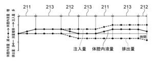
- the present invention is (1) a medical system for injecting a liquid into a body cavity in which cerebrospinal fluid of a subject is present and discharging the liquid present in the body cavity from the body cavity, the medical system being characterized in that it has a control unit that executes control to set a first period during which the liquid is injected into the body cavity and is not discharged from the body cavity, and a second period during which the liquid is not injected into the body cavity and is discharged from the body cavity, alternately repeating the first period and the second period, and setting the amount of the liquid injected in the first period to be substantially the same as the amount of the liquid discharged in the second period.
- the control unit injects liquid into the body cavity during the first period, and does not discharge the liquid from the body cavity. Also, the control unit does not inject liquid into the body cavity during the second period, and discharges the liquid from the body cavity.
- the control unit alternates between the first period and the second period, and makes the amount of liquid injected and the amount of liquid discharged substantially the same. As a result, the injection and discharge of liquid are alternately repeated in the same amount, as long as the allowable fluctuation range of the intracranial pressure is not exceeded. Therefore, the injection and discharge of liquid are not performed simultaneously, and the occurrence of a local steady flow of the liquid injected from the injection port into the body cavity toward the discharge port can be suppressed.
- the liquid injected into the body cavity flows toward the treatment area of the brain according to the injection direction and injection flow rate.
- the liquid and the cerebrospinal fluid are stirred by turbulence caused by the resistance between the liquid injected into the body cavity and the cerebrospinal fluid in the body cavity.
- diffusion due to the concentration difference of oxygen and the like contained in the liquid progresses.
- the liquid can be efficiently delivered to the treatment area of the brain.
- the amount of fluid injected is essentially the same as the amount of fluid removed, the amount of cerebrospinal fluid in the cavity can be kept within a constant range. This helps prevent large fluctuations in intracranial pressure.
- control unit further sets a third period between the first period and the second period, during which the liquid is not injected into the body cavity and the liquid is not discharged from the body cavity.
- diffusion due to the difference in concentration of oxygen and the like contained in the liquid progresses more according to the length of the third period, thereby enabling the liquid to be delivered to the treatment area of the brain more efficiently.
- the third period is longer than the first period.
- the time during which diffusion due to the concentration difference of oxygen and the like contained in the liquid progresses is longer than the time during which the liquid is injected, which allows the liquid to be delivered to the treatment area of the brain more efficiently.
- the third period of time is 1 second or longer. According to the medical system of (5) above, time can be secured for diffusion due to the concentration difference of oxygen and the like contained in the liquid to proceed, thereby enabling the liquid to be efficiently delivered to the treatment area of the brain.
- control unit further sets the third period between the second period and the first period, and that the first time of the third period set between the first period and the second period is longer than the second time of the third period set between the second period and the first period.
- the first time of the pause period (i.e., the third period) between the injection and discharge of the liquid is longer than the second time of the pause period (i.e., the third period) between the discharge and injection of the liquid. This more reliably prevents the occurrence of a local steady flow of the liquid injected from the injection port into the body cavity toward the discharge port, and more reliably ensures time for diffusion due to concentration differences in oxygen and other substances contained in the liquid to proceed. This allows the liquid to be delivered to the treatment area of the brain more efficiently.
- a discharge rate of the liquid during the second period is slower than a supply rate of the liquid during the first period.
- the discharge speed of the liquid in the second period is slower than the injection speed of the liquid in the first period, the speed at which the liquid injected from the injection port into the body cavity moves toward the outlet can be suppressed, and it is possible to ensure that the liquid has enough time to diffuse toward the brain immediately after being injected from the injection port into the body cavity, thereby enabling the liquid to be efficiently delivered to the treatment area of the brain.
- the control unit initially sets a 0th period in which the liquid is injected or discharged in an amount smaller than the injection amount in the first period and the discharge amount in the second period, and starts a period of the first period or the second period in which the liquid moves in a different direction from the 0th period after the 0th period.
- the volume change in the subarachnoid space in the initial zeroth period varies within a range including the original volume. Therefore, it is possible to prevent the volume change from exceeding the allowable variation range. This makes it possible to keep the variation in intracranial pressure within the allowable variation range.
- any of the medical systems (1) to (10) above further includes an injection catheter for injecting the liquid into the body cavity and a drainage catheter for draining the liquid from the body cavity, and it is preferable that the distance between the tip of the injection catheter and the tip of the drainage catheter is 30 centimeters or less when execution of the control begins.
- the injection and discharge of liquid are alternately repeated in equal amounts, so that even if the distance between the tip of the injection catheter and the tip of the discharge catheter is 30 centimeters or less when control execution begins, it is possible to suppress the occurrence of a local steady flow of liquid injected from the injection port into the body cavity toward the discharge port. This makes it possible to efficiently deliver liquid to the treatment area of the brain without inserting the injection catheter deeply into the living body.
- control unit further executes control to contract a balloon that is placed in the body cavity and capable of expanding and contracting during the first period, and to expand the balloon during the second period.
- the control unit injects liquid into the body cavity during the first period, but does not discharge the liquid from the body cavity, and further contracts the balloon placed in the body cavity by the same volume as the liquid.
- the control unit can suppress fluctuations in the volume of the body cavity as a closed space during the first period when the liquid is injected into the body cavity, thereby suppressing fluctuations in intracranial pressure.
- the control unit does not inject liquid into the body cavity during the second period, but discharges the liquid from the body cavity, and further expands the balloon placed in the body cavity by the same volume as the liquid.
- the control unit can suppress fluctuations in the volume of the body cavity as a closed space during the second period when the liquid is discharged from the body cavity, thereby suppressing fluctuations in intracranial pressure.
- slight volume fluctuations may occur due to the difference between the amount of liquid discharged and the amount of balloon expansion, or the difference between the amount of liquid injected and the amount of balloon deflation.
- the amount of volume fluctuation is within the allowable range of the subject's body cavity's own volume fluctuation ability, i.e., the compliance for maintaining intracavity pressure. Therefore, the body deforms in response to a decrease or increase in the amount of liquid, and the volume fluctuations can be countered while maintaining a constant intracranial pressure.
- control unit simultaneously injects the liquid and contracts the balloon during the first period, and simultaneously discharges the liquid and expands the balloon during the second period.
- the control unit simultaneously injects the liquid and deflates the balloon during the first period.
- the control unit can further suppress fluctuations in the volume of the body cavity during the first period when the liquid is injected into the body cavity. This further suppresses fluctuations in intracranial pressure during the first period.
- the control unit simultaneously discharges the liquid and expands the balloon during the second period. This further suppresses fluctuations in the volume of the body cavity during the second period when the liquid is discharged from the body cavity. This further suppresses fluctuations in intracranial pressure during the second period.
- control unit sets the amount of contraction of the balloon during the first period to be substantially equal to the amount of liquid injected, and sets the amount of expansion of the balloon during the second period to be substantially equal to the amount of liquid discharged.
- the control unit sets the balloon contraction amount to be substantially the same as the amount of liquid injected during the first period. Therefore, the amount of liquid increased in the body cavity (i.e., the volume) is substantially the same as the amount by which the balloon contracted in the body cavity (i.e., the volume). Therefore, the volume of the body cavity does not change substantially during the first period. This more reliably suppresses fluctuations in intracranial pressure during the first period.
- the control unit sets the balloon expansion amount to be substantially the same as the amount of liquid discharged during the second period. Therefore, the amount of liquid decreased in the body cavity (i.e., the volume) is substantially the same as the amount by which the balloon expanded in the body cavity (i.e., the volume). Therefore, the volume of the body cavity does not change substantially during the second period. This more reliably suppresses fluctuations in intracranial pressure during the second period.
- control unit further sets a third period between the first period and the second period and between the second period and the first period during which the liquid is not injected into the body cavity and the liquid is not discharged from the body cavity, and maintains the balloon in the contracted state during the third period between the first period and the second period, and maintains the balloon in the expanded state during the third period between the second period and the first period.
- the present invention (16) is a liquid circulation system that injects a liquid into a body cavity in which cerebrospinal fluid is present and discharges the liquid outside the body cavity, the liquid circulation system comprising an injection catheter that injects the liquid into the body cavity, a discharge catheter that discharges the liquid from inside the body cavity to outside the body cavity, a liquid delivery line connected to the injection catheter, a liquid drainage line connected to the drainage catheter, a first liquid delivery unit provided on the liquid delivery line and moving the liquid, a second liquid delivery unit provided on the drainage line and moving the liquid, and a single control unit that controls the first liquid delivery unit and the second liquid delivery unit.
- the liquid circulation system of (16) above is divided into a circuit including the injection catheter and the discharge catheter (i.e., the biological circuit section), and a circuit including the liquid feed line connected to the injection catheter and the liquid drain line connected to the drain catheter (i.e., the system circuit section).
- a first liquid feed section provided on the liquid feed line for moving the liquid and a second liquid feed section provided on the liquid drain line for moving the liquid function as a liquid feed section shared by the biological circuit section and the system circuit section.
- the system circuit section can respond to an increase in the total volume of liquid caused by cavitation and a decrease in the total volume of liquid caused by evaporation while maintaining the condition on the biological side, and the increase or decrease in the liquid in the biological circuit can be minimized. This makes it possible to suppress fluctuations in intracranial pressure.
- the liquid circulation system of (16) above further includes a liquid storage section that stores at least one of the liquid to be injected into the body cavity and the liquid discharged from the body cavity, and a liquid treatment device that is provided in the liquid delivery line between the liquid storage section and the first liquid delivery section and that treats the liquid.
- the liquid treatment device is preferably an oxygenation device that adds oxygen to the liquid discharged outside the body cavity.
- the liquid circulation system described above in (18) enables efficient delivery of highly oxygenated solution to the treatment area of the brain while suppressing fluctuations in intracranial pressure.
- control unit alternately and repeatedly drives the first liquid delivery unit and the second liquid delivery unit.
- the injection and discharge of liquid are repeated alternately in equal amounts, provided that the allowable fluctuation range of intracranial pressure is not exceeded. Therefore, the injection and discharge of liquid are not performed simultaneously, and the occurrence of a local steady flow that occurs when the injection and discharge of liquid are performed simultaneously, that is, a local steady flow in which the liquid injected from the injection port into the body cavity flows toward the discharge port, can be suppressed. Therefore, the liquid injected into the body cavity flows toward the treatment area of the brain according to the injection direction and injection flow rate.
- the liquid and the cerebrospinal fluid are agitated by turbulence caused by resistance between the liquid injected into the body cavity and the cerebrospinal fluid in the body cavity. Furthermore, diffusion progresses due to the concentration difference of oxygen and the like contained in the liquid. This allows the liquid to be efficiently delivered to the treatment area of the brain.
- control unit controls the sum of the injection amount of the liquid ejected while the first liquid delivery unit is operating continuously or intermittently without starting the second liquid delivery unit, and the discharge amount of the liquid ejected while the second liquid delivery unit is operating continuously or intermittently without starting the first liquid delivery unit, from the time of the initial start within a certain range.
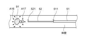
- continuous circulation is a method of continuously injecting and discharging the colored water 911, and is a method as a comparative example. That is, as shown in the table shown in Fig. 16, in “continuous circulation", the control unit 21 sets a period during which the colored water 911 is continuously injected and discharged at a flow rate of 20 mL/min.
- “equal volume withdrawal and receipt” is the method of injection and discharge when the control described above with reference to FIGS. 8 to 11 is executed. That is, as shown in the table shown in FIG. 16, in “equal volume withdrawal and receipt," the control unit 21 sets a first period 211 during which the colored water 911 is injected into the tube 55 and is not discharged from the tube 55, and a second period 212 during which the colored water 911 is not injected into the tube 55 and is discharged from the tube 55.
- the duration of the first period 211 is 3 seconds. In the first period 211, the colored water 911 is injected into the tube 55 over 3 seconds at a flow rate of 20 mL/min, so that the amount of colored water 911 injected is 1 mL.
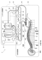
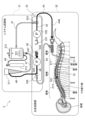
- FIG. 18 is a schematic diagram showing an overview of a liquid circulation system according to this embodiment.
- the liquid circulation system 3 according to the present embodiment circulates a liquid by injecting the liquid into a body cavity and discharging the liquid outside the body cavity.
- An example of the body cavity is a body cavity in which cerebrospinal fluid of a subject is present.
- a case where the liquid injected into the body cavity is a highly oxygenated solution is taken as an example.
- the liquid circulation system 3 includes a system circuit section 31, a biological circuit section 32, and a pump section 33.
- the system circuit section 31 is a section that generates the highly oxygenated solution, adjusts the temperature, and adjusts the total volume of liquid in the circulation circuit, and has a control section 21, a reservoir 311, an oxygenation mechanism 312, and an oxygen supply source 313.
- the oxygenation mechanism 312 of this embodiment is an example of the "liquid treatment device” and “oxygenation device” of the present invention.
- the biological circuit section 32 is a section that injects liquid into the body cavity and expels the liquid from the body cavity, and has a drainage catheter 51 and an injection catheter 52.
- the drainage catheter 51 and the injection catheter 52 are connected to the system circuit section 31 via the pump section 33.
- the drainage catheter 51 and the injection catheter 52 are as described above with reference to Figures 1 to 17.
- the pump section 33 functions as a liquid delivery section shared by the system circuit section 31 and the biological circuit section 32.
- the pump section 33 has a first liquid storage section 331, a first pump 332, a first flow path switching section 333, a second liquid storage section 334, a second pump 335, and a second flow path switching section 336.
- the first pump 332 of this embodiment is an example of the "first liquid delivery section" of the present invention.
- the second pump 335 of this embodiment is an example of the "second liquid delivery section" of the present invention.
- the pump section 33 may have a first drive section 23 and a second drive section 24.
- the oxygenation mechanism 312 supplies the oxygenated cerebrospinal fluid as a highly oxygenated solution to the first flow path switching unit 333 via the first tube 41.
- a hollow fiber type artificial lung for adding oxygen to blood can be used as the oxygenation mechanism 312 in this embodiment.
- the first flow path switching unit 333 is provided at the connection between the first tube 41, the second tube 42, and the third tube 43, and can switch between a flow path connecting the first tube 41 and the second tube 42 and a flow path connecting the second tube 42 and the third tube 43.
- the first drive unit 23 controls the operation of the first flow path switching unit 333 based on a control signal transmitted from the control unit 21, and switches between a flow path connecting the first tube 41 and the second tube 42 and a flow path connecting the second tube 42 and the third tube 43.
- the first tube 41, the second tube 42, and the third tube 43 are an example of a "liquid delivery line" of the present invention, and are connected to the first liquid storage unit 331 and the injection catheter 52.
- the first flow path switching unit 333 is connected to the first liquid storage unit 331 via the second tube 42.
- the first pump 332 is provided in the second tube 42. Examples of the first pump 332 include a roller pump and a syringe pump. The first pump 332 operates based on a control signal sent from the control unit 21, and moves liquid toward the first liquid storage unit 331 or toward the first flow path switching unit 333.
- the first pump 332 When the first pump 332 is driven in the first direction while the first flow path switching unit 333 is connecting the first tube 41 and the second tube 42, the first pump 332 supplies the liquid (i.e., the highly oxygenated solution) generated in the oxygenation mechanism 312 to the first liquid storage unit 331 through the first tube 41 and the second tube 42. As a result, the first liquid storage unit 331 stores the liquid supplied from the oxygenation mechanism 312 through the first tube 41 and the second tube 42. Note that when the first pump 332 is driven in the second direction while the first flow path switching unit 333 is connecting the first tube 41 and the second tube 42, the first pump 332 supplies the liquid stored in the first liquid storage unit 331 to the oxygenation mechanism 312 through the first tube 41 and the second tube 42.
- the liquid i.e., the highly oxygenated solution
- the first pump 332 supplies the liquid stored in the first liquid storage unit 331 to the injection catheter 52 through the second tube 42 and the third tube 43.
- the reservoir 311 is connected to the second flow path switching unit 336 via the sixth tube 46.
- the reservoir 311 is also connected to the oxygenation mechanism 312 via the seventh tube 47.
- the reservoir 311 temporarily stores the cerebrospinal fluid supplied through the sixth tube 46.
- the reservoir 311 then supplies the stored cerebrospinal fluid to the oxygenation mechanism 312 through the seventh tube 47.
- the reservoir 311 has a structure in which the inside and outside are connected to each other, and gas contained in the stored cerebrospinal fluid can be released to the outside. In other words, the reservoir 311 functions as an air trap.
- the second flow path switching unit 336 is provided at the connection between the fourth tube 44, the fifth tube 45, and the sixth tube 46, and can switch between a flow path connecting the fourth tube 44 and the fifth tube 45 and a flow path connecting the fifth tube 45 and the sixth tube 46.
- the second drive unit 24 controls the operation of the second flow path switching unit 336 based on a control signal transmitted from the control unit 21, and switches between a flow path connecting the fourth tube 44 and the fifth tube 45 and a flow path connecting the fifth tube 45 and the sixth tube 46.
- the fourth tube 44, the fifth tube 45, and the sixth tube 46 are an example of a "drainage line" of the present invention, and are connected to the second liquid storage unit 334 and the discharge catheter 51.
- the second flow path switching unit 336 is connected to the second liquid storage unit 334 via the fifth tube 45.
- the second pump 335 is provided in the fifth tube 45. Examples of the second pump 335 include a roller pump and a syringe pump. The second pump 335 operates based on a control signal sent from the control unit 21, and moves liquid toward the second liquid storage unit 334 or toward the second flow path switching unit 336.
- the second pump 335 supplies the liquid (i.e., cerebrospinal fluid) discharged from inside the body cavity to outside the body cavity through the fourth tube 44 and the fifth tube 45 to the second liquid storage unit 334.
- the second liquid storage unit 334 stores the liquid (i.e., cerebrospinal fluid) discharged from inside the body cavity to outside the body cavity through the fourth tube 44 and the fifth tube 45.
- the second pump 335 when the second pump 335 is driven in the first direction while the second flow path switching unit 336 is connecting the fifth tube 45 and the sixth tube 46, the second pump 335 supplies the cerebrospinal fluid stored in the reservoir 311 to the second liquid storage unit 334 via the fifth tube 45 and the sixth tube 46.
- the second liquid storage unit 334 stores the liquid (i.e., cerebrospinal fluid) supplied from the reservoir 311 through the fifth tube 45 and the sixth tube 46.
- the second pump 335 When the second pump 335 is driven in the second direction while the second flow path switching unit 336 is connecting the fifth tube 45 and the sixth tube 46, the second pump 335 supplies the liquid (i.e., cerebrospinal fluid) stored in the second liquid storage unit 334 to the reservoir 311 through the fifth tube 45 and the sixth tube 46.
- liquid i.e., cerebrospinal fluid
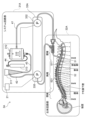
- FIGS. 19 to 22 are schematic diagrams illustrating the operation of the liquid circulation system according to this embodiment.
- the operation of the liquid circulation system 3 described with reference to FIGS. 19 to 22 is based on the control described above with reference to FIGS.
- the control unit 21, the first drive unit 23, and the second drive unit 24 are omitted in Figures 19 to 22.
- the operation described below will be described assuming that the operation starts from a primed state in which the tubes, reservoirs, and oxygenation mechanisms in the circuit are filled with artificial cerebrospinal fluid such as lactated Ringer's solution.
- the control unit 21 sends a control signal to the first drive unit 23 to control the operation of the first flow path switching unit 333 and connects the first tube 41 and the second tube 42.
- the control unit 21 also sends a control signal to the second drive unit 24 to control the operation of the second flow path switching unit 336 and connects the fourth tube 44 and the fifth tube 45.
- the control unit 21 sends a control signal to the first pump 332 to drive the first pump 332 in the second direction, and sends a control signal to the second pump 335 to drive the second pump 335 in the first direction.
- the liquid 91 (see FIG. 20) stored in the first liquid storage section 331 is returned to the oxygenation mechanism 312 through the first tube 41 and the second tube 42.
- the cerebrospinal fluid 92 in the body cavity is sucked into the outlet 511 of the drainage catheter 51.
- the cerebrospinal fluid 92 is supplied to the second liquid storage section 334 through the fourth tube 44 and the fifth tube 45 and stored therein.
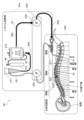
- the control unit 21 sends a control signal to the first drive unit 23 to control the operation of the first flow path switching unit 333, and connects the first tube 41 and the second tube 42.
- the control unit 21 also sends a control signal to the second drive unit 24 to control the operation of the second flow path switching unit 336, and connects the fifth tube 45 and the sixth tube 46.
- the control unit 21 sends a control signal to the first pump 332 to drive the first pump 332 in the first direction, and sends a control signal to the second pump 335 to drive the second pump 335 in the second direction.
- the liquid 91 (i.e., the highly oxygenated solution) produced in the oxygenation mechanism 312 is supplied to and stored in the first liquid storage section 331 through the first tube 41 and the second tube 42.
- the cerebrospinal fluid 92 stored in the second liquid storage section 334 is supplied to and stored in the reservoir 311 through the fifth tube 45 and the sixth tube 46.
- the cerebrospinal fluid 92 stored in the reservoir 311 is supplied to the oxygenation mechanism 312 through the seventh tube 47.
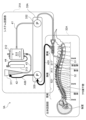
- control unit 21 in the third step, sends a control signal to the first drive unit 23 to control the operation of the first flow path switching unit 333, and connects the second tube 42 and the third tube 43.
- the control unit 21 also sends a control signal to the second drive unit 24 to control the operation of the second flow path switching unit 336, and connects the fifth tube 45 and the sixth tube 46.
- the control unit 21 sends a control signal to the first pump 332 to drive the first pump 332 in the second direction, and sends a control signal to the second pump 335 to drive the second pump 335 in the first direction.
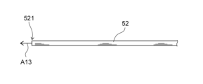
- the liquid 91 (i.e., the highly oxygenated solution) stored in the first liquid storage section 331 is supplied to the injection catheter 52 through the second tube 42 and the third tube 43. Then, for example, as shown by arrow A13 in FIG. 21, the liquid 91 is injected into the body cavity from the injection port 521 of the injection catheter 52. Meanwhile, as shown by arrow A47 in FIG. 21, the cerebrospinal fluid 92 stored in the reservoir 311 is returned to the second liquid storage section 334 through the fifth tube 45 and the sixth tube 46.
- the control unit 21 sends a control signal to the first drive unit 23 to control the operation of the first flow path switching unit 333, and connects the first tube 41 and the second tube 42.
- the control unit 21 also sends a control signal to the second drive unit 24 to control the operation of the second flow path switching unit 336, and connects the fifth tube 45 and the sixth tube 46.
- the control unit 21 sends a control signal to the first pump 332 to drive the first pump 332 in the first direction, and sends a control signal to the second pump 335 to drive the second pump 335 in the second direction.
- the liquid 91 (i.e., the highly oxygenated solution) produced in the oxygenation mechanism 312 is supplied to and stored in the first liquid storage section 331 through the first tube 41 and the second tube 42.
- the cerebrospinal fluid 92 stored in the second liquid storage section 334 is supplied to and stored in the reservoir 311 through the fifth tube 45 and the sixth tube 46.
- the cerebrospinal fluid 92 stored in the reservoir 311 is supplied to the oxygenation mechanism 312 through the seventh tube 47.
- the circuit for circulating the liquid is divided into a circuit including the injection catheter 52 and the discharge catheter 51 (i.e., the biological circuit section 32) and a circuit including the liquid supply lines (i.e., the first tube 41, the second tube 42, the third tube 43) connected to the injection catheter 52 and the liquid drainage lines (i.e., the fourth tube 44, the fifth tube 45, the sixth tube 46) connected to the discharge catheter 51 (i.e., the system circuit section 31).
- the first pump 332 provided on the liquid supply line for moving the liquid and the second pump 335 provided on the liquid drainage line for moving the liquid function as a shared pump in the biological circuit section 32 and the system circuit section 31.
- the system circuit section 31 can respond to the increase in the total volume of the liquid caused by the cavitation phenomenon and the decrease in the total volume of the liquid caused by evaporation while maintaining the condition on the biological side, and the increase or decrease in the amount of liquid in the biological circuit can be suppressed. This can suppress fluctuations in intracranial pressure.
- the control unit 21 also repeatedly drives the first pump 332, the second pump 335, the first flow path switching unit 333, and the second flow path switching unit 336 to switch the direction of the liquid flow so as to perform the operation shown in Figures 19 to 22.
- the injection of the liquid 91 and the discharge of the cerebrospinal fluid 92 are alternately repeated in equal amounts as long as the allowable fluctuation range of the intracranial pressure is not exceeded.
- the control unit 21 does not control the first flow path switching unit 333 to connect the second tube 42 and the third tube 43 and the second flow path switching unit 336 to connect the fourth tube 44 and the fifth tube 45 at the same time, so that the injection of the liquid 91 and the discharge of the cerebrospinal fluid 92 are not performed simultaneously, and the occurrence of a local steady flow of the liquid 91 injected into the body cavity from the injection port 521 of the injection catheter 52 toward the discharge port 511 of the discharge catheter 51 can be suppressed. Therefore, the liquid 91 injected into the body cavity flows toward the treatment area of the brain according to the injection direction and injection flow rate.
- the control unit 21 also controls the sum of the amount of fluid injected into the biological circuit unit 32 while the first pump 332 is operating continuously or intermittently in the third step and the amount of fluid discharged from the biological circuit unit 32 while the second pump 335 is operating continuously or intermittently in the first step, from the time of initial startup, to within a certain range.
- This makes it possible to keep fluctuations in the amount of cerebrospinal fluid from the time of initial startup of the first pump 332 and the second pump 335 within a certain range.
- This makes it possible to more reliably keep intracranial pressure from exceeding the allowable fluctuation range.
- This makes it possible to more reliably keep fluctuations in intracranial pressure within the allowable fluctuation range.
- the highly oxygenated solution can be efficiently delivered to the treatment area of the brain while suppressing fluctuations in intracranial pressure.
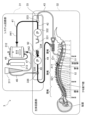
- FIG. 23 is a schematic diagram illustrating an overview of a liquid circulation system according to a first modified example of this embodiment.
- the liquid circulation system 3A according to this modification circulates a liquid by injecting the liquid into a body cavity and discharging it outside the body cavity.
- An example of the body cavity is a body cavity in which cerebrospinal fluid of a subject is present.
- a case where the liquid injected into the body cavity is a highly oxygenated solution is taken as an example.
- the liquid circulation system 3A includes a system circuit section 31A, a biological circuit section 32A, and a pump section 33A.
- the system circuit section 31A is a section that generates the highly oxygenated solution, adjusts the temperature, and adjusts the total volume of liquid in the circulation circuit, and has a control section 21, a reservoir 311, an oxygenation mechanism 312, and an oxygen supply source 313.
- the oxygenation mechanism 312 of this modified example is an example of the "liquid treatment device” and "oxygenation device” of the present invention.
- the biological circuit section 32A is a section that injects liquid into the body cavity and expels liquid from the body cavity, and has a drainage catheter 51 and an injection catheter 52.
- the drainage catheter 51 and the injection catheter 52 are connected to the pump section 33A and the system circuit section 31A, which includes the reservoir 311 and the oxygenation mechanism 312.
- the drainage catheter 51 and the injection catheter 52 are as described above with reference to Figures 1 to 17.
- the pump section 33A functions as a liquid delivery section shared by the system circuit section 31A and the biological circuit section 32A.
- the pump section 33A has a first pump 332 and a second pump 335.
- the first pump 332 and the second pump 335 can be a roller pump that delivers liquid in a liquid delivery tube by squeezing the tube with a roller, or a peristaltic pump that delivers liquid in a tube by squeezing the tube with multiple fingers.
- the oxygenation mechanism 312 is connected to the injection catheter 52 via the first tube 41.
- the oxygenation mechanism 312 is also connected to the reservoir 311 via the third tube 43.
- the oxygenation mechanism 312 is further connected to the oxygen supply source 313 via the fourth tube 44.
- the oxygenation mechanism 312 mixes the cerebrospinal fluid or lactate Ringer's solution or a mixture thereof supplied from the reservoir 311 via the third tube 43 with the oxygen supplied from the oxygen supply source 313 via the fourth tube 44 to generate oxygenated cerebrospinal fluid.
- the oxygenation mechanism 312 also has a heat exchanger that adjusts the temperature of the oxygenated cerebrospinal fluid.
- the oxygenation mechanism 312 supplies the oxygenated cerebrospinal fluid as a highly oxygenated solution to the injection catheter 52 via the first tube 41.
- a hollow fiber type artificial lung for adding oxygen to blood can be used as the oxygenation mechanism 312 in this modified example.
- the first pump 332 is provided on the path of the first tube 41.
- the first pump 332 operates based on a control signal sent from the control unit 21, and moves liquid from the oxygenation mechanism 312 toward the injection catheter 52.
- the first pump 332 When the first pump 332 is driven, it supplies the liquid (i.e., the highly oxygenated solution) produced in the oxygenation mechanism 312 through the first tube 41 to the injection catheter 52, and ultimately injects it into the body cavity.
- the liquid i.e., the highly oxygenated solution
- the reservoir 311 is connected to the drainage catheter 51 via the second tube 42.
- the reservoir 311 is also connected to the oxygenation mechanism 312 via the third tube 43.
- the reservoir 311 temporarily stores the cerebrospinal fluid supplied through the second tube 42.
- the reservoir 311 then supplies the stored cerebrospinal fluid to the oxygenation mechanism 312 through the third tube 43.
- the reservoir 311 has a structure in which the inside and outside are connected to each other, and gas contained in the stored cerebrospinal fluid can be released to the outside. In other words, the reservoir 311 functions as an air trap.
- the second pump 335 is provided on the second tube 42.
- the second pump 335 operates based on a control signal sent from the control unit 21, and moves liquid from the discharge catheter 51 toward the reservoir 311.
- the second pump 335 When the second pump 335 is driven, the second pump 335 supplies the liquid (i.e., cerebrospinal fluid) discharged from inside the body cavity to outside the body cavity through the discharge catheter 51 to the reservoir 311. As a result, the reservoir 311 stores the liquid (i.e., cerebrospinal fluid) discharged from inside the body cavity to outside the body cavity through the discharge catheter 51.
- the liquid i.e., cerebrospinal fluid
- FIGS. 24 and 25 are schematic diagrams illustrating the operation of the liquid circulation system according to this modified example.
- the operation of the liquid circulation system 3A described with reference to FIGS. 24 to 25 is based on the control described above with reference to FIGS.
- the control unit 21 is omitted in Figures 24 and 25.
- the operation described below will be described assuming that the operation starts from a primed state in which the tubes, reservoirs, and oxygenation mechanisms in the circuit are filled with artificial cerebrospinal fluid such as lactated Ringer's solution.
- the control unit 21 also alternately drives the first pump 332 and the second pump 335. Therefore, as long as the allowable fluctuation range of the intracranial pressure is not exceeded, the injection of the liquid 91 and the discharge of the cerebrospinal fluid 92 are alternately repeated in the same amount. Therefore, the injection of the liquid 91 and the discharge of the cerebrospinal fluid 92 are not performed simultaneously, and the occurrence of a local steady flow of the liquid 91 injected into the body cavity from the inlet 521 of the injection catheter 52 toward the outlet 511 of the discharge catheter 51 can be suppressed. Therefore, the liquid 91 injected into the body cavity flows toward the treatment area of the brain according to the injection direction and injection flow rate.
- the system circuit section 31B is the section that generates the highly oxygenated solution and adjusts the temperature, as well as adjusts the total volume of liquid in the circulation circuit, and includes the control section 21, a reservoir 311, an oxygenation mechanism 312, an oxygen supply source 313, and a heat exchanger 314.
- the biological circuit section 32B is a section that injects liquid into the body cavity and expels liquid from the body cavity, and includes a drainage catheter 51, an injection catheter 52, and a balloon catheter 54B.
- the drainage catheter 51 and the injection catheter 52 are connected to the pump section 33B and the system circuit section 31B, which includes the reservoir 311 and the oxygenation mechanism 312.
- the drainage catheter 51 and the injection catheter 52 are as described above with reference to Figures 1 to 17. Note that in the liquid circulation system 3B of this modified example, the injection catheter 52 is not disposed in the lumen 513 (see Figure 4) of the drainage catheter 51, and exists separately from the drainage catheter 51.
- the biological circuit section 32B further includes a balloon syringe 544, a balloon piston 545, and a fourth drive section 26.
- the balloon syringe 544 of this modified example is an example of a "balloon fluid storage section" of the present invention
- the balloon syringe 544 and the balloon piston 545 are an example of a "balloon drive section” of the present invention.
- the "balloon drive section" of the present invention includes the balloon syringe 544 and the balloon piston 545.
- the fourth drive section 26 of this modified example is an example of a "piston drive section" of the present invention.
- the balloon catheter 54B has a balloon 54 at its tip.
- the fourth drive unit 26 moves the balloon piston 545 in the insertion direction of the balloon syringe 544 based on a control signal sent from the control unit 21, the expansion fluid 93 stored in the balloon syringe 544 passes through the inner cavity of the balloon catheter 54B and flows toward the tip of the balloon catheter 54B.
- the expansion fluid 93 that has flowed toward the tip of the balloon catheter 54B is then supplied to the inside of the balloon 54 through a hole formed in the tip of the balloon catheter 54B.
- the expansion fluid 93 expands the balloon 54. In other words, the balloon 54 is inflated.
- the fourth drive unit 26 moves the balloon piston 545 in the direction of removing the balloon syringe 544 based on a control signal sent from the control unit 21, the expansion fluid 93 stored in the balloon 54 is sucked into and stored in the balloon syringe 544. This causes the expansion fluid 93 to be discharged from the balloon 54, causing the balloon 54 to contract.
- the balloon 54 is designed so that it does not strongly compress the subarachnoid space near the lumbar vertebrae into which the balloon catheter 54B is inserted, even at maximum expansion.
- the cross-sectional area of the spinal cavity is not perfectly circular. Furthermore, the spine in which the spinal cavity is located is gently S-shaped overall, and may be deformed due to aging, trauma, disease, etc. Therefore, it is desirable for the balloon 54 to be a compliant balloon made of an elastic material (stretchable material) such as rubber or elastomer, and whose volume changes depending on the amount of expansion fluid injected. A compliant balloon can deform to follow the shape of the spinal cavity.
- an elastic material such as rubber or elastomer
- the balloon 54 may have a structure in which, for example, multiple inflatable parts are provided in the axial direction, and the balloons are connected by a flexible material. This structure makes it possible to shorten the axial dimension (length) of each balloon and limit the outer diameter of each balloon when expanded to a certain value or less.
- each balloon may be independent, and the expansion fluid is injected from multiple positions separated in the axial direction, so that the balloon can be expanded uniformly without changing the total volume of the entire balloon when expanded, compared to when the balloon is composed of only one space, and the connection between the balloons becomes an inflection point, making it easier to follow the shape of the spinal cavity.
- the balloon 54 may also have a structure having multiple independent balloon catheters. Since each balloon catheter can be operated independently, the balloons can be moved and positioned to fill gaps according to the shape and cross-sectional area of the spinal cavity. By implementing this structure, the risk of strong compression of a part of the spinal cord due to the expansion of the balloon 54 is reduced, so that the load on the living body can be further reduced.
- the balloon 54 is not particularly limited in shape, etc., as long as it can follow the shape and cross-sectional area of the spinal cavity and does not strongly compress the spinal cord.
- the expansion fluid 93 may be a liquid or a gas.
- Examples of the expansion fluid 93 include saline, cerebrospinal fluid, and air.
- the expansion fluid 93 may be a fluid different from the liquid injected into the body cavity, or may be the same fluid as the liquid injected into the body cavity.
- the material of the balloon 54 may be, for example, an elastic material (i.e., a compliant material) made of elastomers such as silicone and natural rubber, or rubber.
- a compliant material made of elastomers such as silicone and natural rubber, or rubber.
- the material of the balloon 54 is not limited to these.
- Pump section 33B functions as a liquid delivery section shared by system circuit section 31B and biological circuit section 32B.
- Pump section 33B has a first pump 337 and a second pump 338.
- the first pump 337 of this modified example is an example of a "first liquid delivery section" of the present invention.
- the second pump 338 of this modified example is an example of a "second liquid delivery section" of the present invention.
- Examples of the first pump 337 and the second pump 338 include an infusion pump and a syringe pump.
- the oxygenation mechanism 312 is connected to the first pump 337 via the first tube 41.
- the first pump 337 is connected to the injection catheter 52.
- the oxygenation mechanism 312 is also connected to the reservoir 311 via the fifth tube 45.
- the oxygenation mechanism 312 is further connected to the oxygen supply source 313 via the sixth tube 46.
- the oxygenation mechanism 312 mixes the cerebrospinal fluid or lactate Ringer's solution or a mixture thereof supplied from the reservoir 311 via the fifth tube 45 with the oxygen supplied from the oxygen supply source 313 via the sixth tube 46 to generate oxygenated cerebrospinal fluid.
- the oxygenation mechanism 312 is also connected to the heat exchanger 314 via the seventh tube 47 and the eighth tube 48.
- the heat exchanger 314 adjusts the temperature of the oxygenated cerebrospinal fluid to about 37°C.
- the temperature adjustment by the heat exchanger is, for example, about 32°C to 40°C.
- the oxygenation mechanism 312 supplies oxygenated cerebrospinal fluid as a highly oxygenated solution to the infusion catheter 52 through the first tube 41 and the first pump 337.
- a hollow fiber membrane oxygenator for adding oxygen to blood can be used as the oxygenation mechanism 312 in this modified example.
- the first pump 337 is connected to the first tube 41 and the injection catheter 52, and is disposed between the first tube 41 and the injection catheter 52.
- the first tube 41 of this modified example is an example of the "liquid delivery line" of the present invention. That is, the first tube 41 is connected to the injection catheter 52 via the first pump 337.
- the first pump 337 operates based on a control signal sent from the control unit 21, and moves liquid from the oxygenation mechanism 312 toward the injection catheter 52.
- the first pump 337 When the first pump 337 is driven, the first pump 337 supplies the liquid (i.e., the highly oxygenated solution) produced in the oxygenation mechanism 312 through the first tube 41 to the injection catheter 52, and ultimately injects it into the body cavity.
- the liquid i.e., the highly oxygenated solution
- the reservoir 311 is connected to the second pump 338 via the fourth pipe 44.
- the reservoir 311 is also connected to the oxygenation mechanism 312 via the fifth pipe 45.
- the reservoir 311 temporarily stores the cerebrospinal fluid supplied through the fourth pipe 44.
- the reservoir 311 then supplies the stored cerebrospinal fluid to the oxygenation mechanism 312 through the fifth pipe 45.
- the reservoir 311 has a structure in which the inside and outside are connected to each other, and gas contained in the stored cerebrospinal fluid can be released to the outside. In other words, the reservoir 311 functions as an air trap.
- the second pump 338 is connected to the fourth tube 44 and the discharge catheter 51, and is disposed between the fourth tube 44 and the discharge catheter 51.
- the fourth tube 44 of this modified example is an example of the "drainage line" of the present invention. That is, the fourth tube 44 is connected to the discharge catheter 51 via the second pump 338.
- the second pump 338 operates based on a control signal sent from the control unit 21, and moves liquid from the discharge catheter 51 toward the reservoir 311.
- the second pump 338 When the second pump 338 is driven, the second pump 338 supplies the liquid (i.e., cerebrospinal fluid) discharged from inside the body cavity to outside the body cavity through the discharge catheter 51 to the reservoir 311 through the fourth tube 44. As a result, the reservoir 311 stores the liquid (i.e., cerebrospinal fluid) discharged from inside the body cavity to outside the body cavity through the discharge catheter 51.
- the liquid i.e., cerebrospinal fluid
- the liquid circulation system 3B may have a balloon catheter 54B with a balloon 54 at its tip.
- the control unit 21 can suppress fluctuations in the volume of the body cavity as a closed space by controlling the operation of the first pump 337 and the operation of the second pump 338 and the expansion and contraction of the balloon 54 arranged in the body cavity. Therefore, the body cavity can change its volume in a high compliance region and deform in accordance with the amount of liquid that has decreased or increased in the body cavity. This suppresses fluctuations in intracranial pressure.
- control unit 21 controls each of the first pump 337 and the second pump 338 and further controls the expansion and contraction of the balloon 54, thereby more appropriately setting the timing and speed of the injection of the liquid 91 and the contraction of the balloon 54, as well as the timing and speed of the discharge of the liquid 91 and the expansion of the balloon 54. This further suppresses fluctuations in intracranial pressure.
- FIG. 27 is a schematic diagram showing a modified example of the medical device of this embodiment.
- the components of the medical device 5B shown in Figure 27 are similar to the components of the medical device 5 described above with reference to Figures 2 to 4, duplicated explanations will be omitted as appropriate, and the following explanation will focus on the differences.
- the medical device 5B shown in FIG. 27 has a drainage catheter 51, an injection catheter 52B, and a balloon 54, and is used, for example, in the liquid circulation system 3B described above with reference to FIG. 26.
- the balloon 54 is provided at the tip of the injection catheter 52B.
- the injection catheter 52B has a balloon 54 at its tip.
- the drainage catheter 51 is as described above with reference to FIGS. 2 to 4.
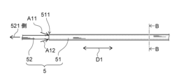
- the injection catheter 52B is disposed in the lumen 513 of the discharge catheter 51 and is not connected to the discharge catheter 51. Therefore, the injection catheter 52B can move in the lumen 513 of the discharge catheter 51 along the longitudinal direction D1 of the discharge catheter 51. Since the tip of the discharge catheter 51 opens as the discharge port 511, as shown in FIG. 27, the tip of the injection catheter 52B (i.e., the portion where the balloon 54 is provided) can pass through the discharge port 511 of the discharge catheter 51.
- the medical device 5B has a structure in which only the injection catheter 52B and the balloon 54 are integrally formed, and are not connected to the discharge catheter 51. With this structure, it is possible to change the positions of the injection catheter and the discharge catheter, and therefore it is possible to position the injection catheter according to the shape of the patient's spinal cavity.
- the balloon 54 in this embodiment is not limited to being formed integrally with the injection catheter.
- the balloon 54 may be formed separately from the injection catheter and provided at the tip of the balloon catheter 54B.
- the distance in the longitudinal direction D1 between the tip of the discharge catheter 51 and the tip of the injection catheter 52B exposed from the discharge port 511 of the discharge catheter 51 is preferably, for example, 0 mm or more and 300 mm or less.
- the cross-sectional area of a typical spinal cavity is about 6.7 mm 2 to 16.7 mm 2 and that the discharge catheter 51 is disposed in the spinal cavity separately from the balloon 54
- the cross-sectional area of the balloon 54 is preferably about half that area, for example, about 3.3 mm 2 to 8.3 mm 2.
- the length of the balloon 54 along the longitudinal direction D1 is, for example, about 1 mm to 300 mm, preferably 36 mm to 200 mm.
- the balloon 54 and the discharge port 511 at the tip of the discharge catheter 51 come into contact with each other and can function without interfering with each other.
- the expansion fluid supplied from the base end of the injection catheter 52B passes through the lumen 542B formed inside the injection catheter 52B and flows toward the tip of the injection catheter 52B. Then, as shown by arrow A4 in FIG. 27, the expansion fluid flowing toward the tip of the injection catheter 52B passes through a hole 541B formed at the tip of the injection catheter 52B and is supplied to the inside of the balloon 54. As a result, the expansion fluid expands the balloon 54. In other words, the balloon 54 expands. On the other hand, when the expansion fluid is discharged from the balloon 54, the balloon 54 contracts.
- the drainage catheter 51 draws cerebrospinal fluid present in the subarachnoid space near the lumbar vertebrae into space 53 through drainage port 511. Also, as shown by arrow A10 in FIG. 27, the drainage catheter 51 draws cerebrospinal fluid present in the subarachnoid space near the lumbar vertebrae into space 53 through multiple holes 512. Then, as shown by arrow A6 in FIG. 27, the drainage catheter 51 drains cerebrospinal fluid out of the subject's body cavity through space 53.
- injection catheter 52B injects liquid from injection port 521 through lumen 523 of injection catheter 52B into cerebrospinal fluid present in the subarachnoid space.
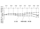
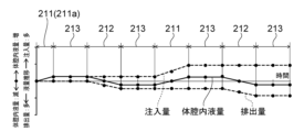
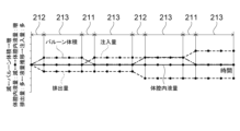
- FIG. 28 is a graph showing the relationship between the injection amount, the discharge amount, the balloon volume, and the amount of fluid in the body cavity under the control of the medical system according to the second modification of this embodiment.
- the case where the medical device 5B described above with reference to FIG. 27 is used will be taken as an example.
- the horizontal axis of the graph shown in FIG. 28 represents time.
- the vertical axis of the graph shown in FIG. 28 represents the change in the volume of fluid.
- the "injection volume” shown in FIG. 28 represents the cumulative volume of fluid 91 injected into the body cavity from the start of control execution.
- the “discharge volume” shown in FIG. 28 represents the cumulative volume of cerebrospinal fluid discharged outside the body cavity from the start of control execution.
- the "volume of fluid in the body cavity” shown in FIG. 28 represents the change in the volume of cerebrospinal fluid present in the body cavity at the start of control execution.
- the vertical axis of the graph shown in FIG. 28 represents the change in the volume of the balloon 54.
- control unit 21 sets a second period 212 during which the liquid 91 is not injected into the body cavity, the liquid 91 is discharged from the body cavity, and the balloon 54 placed in the body cavity is expanded, and a first period 211 during which the liquid 91 is injected into the body cavity, the liquid 91 is not discharged from the body cavity, and the balloon 54 is deflated.
- the drainage catheter 51 draws cerebrospinal fluid 92 (including liquid 91) present in the subarachnoid space near the lumbar vertebrae into space 53 through multiple holes 512, and drains it to the outside of the subject's body cavity through space 53.
- the expansion fluid 93 is supplied from the base end of the medical device 5B, passes through the lumen 542B, and is supplied to the inside of the balloon 54 through hole 541B. This causes the balloon 54 to expand.
- control unit 21 can suppress fluctuations in the volume of the body cavity as a closed space during the second period 212 in which cerebrospinal fluid 92 (including liquid 91) is discharged from the body cavity. Therefore, the volume of the body cavity can fluctuate in the high compliance region, and the body cavity can deform in response to the reduced amount of liquid in the body cavity. Therefore, fluctuations in intracranial pressure during the second period 212 are suppressed.
- the amount of liquid reduced in the body cavity i.e., the volume
- the amount by which the balloon 54 expands in the body cavity i.e., the volume. Therefore, the volume of the body cavity does not substantially change during the second period 212. This more reliably suppresses fluctuations in intracranial pressure during the second period 212.
- the injection catheter 52B injects the liquid 91 supplied from the base end of the injection catheter 52B through the lumen 523 into the cerebrospinal fluid present in the subarachnoid space from the injection port 521. Also, during the first period 211, the expansion fluid 93 inside the balloon 54 passes through the hole 541B and the lumen 542B and is discharged to the outside of the balloon 54. This causes the balloon 54 to contract.
- control unit 21 can suppress fluctuations in the volume of the body cavity as a closed space during the first period 211 in which the liquid 91 is injected into the body cavity. Therefore, the volume of the body cavity can be changed in a high compliance region, and the body cavity can deform in response to the increased amount of liquid in the body cavity. Therefore, fluctuations in intracranial pressure during the first period 211 are suppressed.
- the control unit 21 simultaneously injects the liquid 91 and deflates the balloon 54 during the first period 211. Furthermore, the control unit 21 sets the amount of deflation of the balloon 54 (i.e., the amount of expansion fluid 93 discharged from the balloon 54) during the first period 211 to be substantially the same as the amount of liquid 91 injected.
- the amount of liquid (i.e., volume) increased within the body cavity is substantially the same as the amount (i.e., volume) by which the balloon 54 is deflated within the body cavity. Therefore, the volume of the body cavity does not substantially change during the first period 211. This more reliably suppresses fluctuations in intracranial pressure during the first period 211.
- the control unit 21 further sets a third period 213, during which the liquid 91 is not injected into the body cavity and the liquid 91 is not discharged from the body cavity, between the second period 212 and the first period 211 and between the first period 211 and the second period 212. That is, during the third period 213, the injection of the liquid 91 into the body cavity and the discharge of the liquid 91 from the body cavity are stopped simultaneously.
- the control unit 21 repeats the second period 212, the third period 213, the first period 211, and the third period 213 in this order.
- the third period as shown by the arrows A24 and A25 in FIG.
- the duration of the third period 213 is preferably until the flow caused by the previous injection or discharge has disappeared, and specifically, is preferably 1 second or more.
- the control unit 21 executes control to maintain the balloon 54 in an expanded state during the third period 213 between the second period 212 and the first period 211.
- the control unit 21 maintains a state in which the expansion fluid 93 is supplied to the inside of the balloon 54 during the third period 213 between the second period 212 and the first period 211, thereby maintaining the balloon 54 in an expanded state.
- control unit 21 executes control to maintain the balloon 54 in a contracted state during a third period between the first and second periods.
- the control unit 21 maintains the balloon 54 in a contracted state by maintaining a state in which the expansion fluid 93 is discharged outside the balloon 54 during the third period between the first and second periods.
- the amount of liquid (i.e., volume) that increases or decreases in the body cavity is substantially the same as the amount of the balloon 54 that increases or decreases in the body cavity. Therefore, the volume of the body cavity does not change substantially. This suppresses fluctuations in intracranial pressure. Furthermore, since the volume of the body cavity does not change substantially, the body cavity can change its volume in a high compliance region regardless of the amount of liquid 91 injected, and can deform in response to the amount of liquid that increases or decreases in the body cavity. Therefore, even if the balance of the amount of liquid is somewhat lost, the body cavity can respond by compliance. Furthermore, since the volume of the body cavity does not change substantially regardless of the amount of liquid 91 injected, the amount of liquid 91 injected can be increased as long as there is space for the balloon 54 to expand.
- the amount of fluid injected into the balloon and the amount of fluid discharged from the balloon are limited to "(total of n balloon injections) - (total of n-1 balloon discharges) ⁇ nth discharge.”
- the amount of fluid discharged at one time is not particularly limited as long as it does not exceed the volume of the spinal cavity, and is, for example, about 1 mL to 30 mL.
- the amount of fluid injected at one time is about 1 mL to 30 mL, and more preferably about 3 to 10 mL considering the cross-sectional area of the balloon 54 and the length that can be placed along the longitudinal direction D1.
- control unit 21 further sets a third period 213 between the second period 212 and the first period 211 and between the first period 211 and the second period 212, during which the liquid 91 is not injected into the body cavity and the liquid 91 is not discharged from the body cavity. Therefore, the diffusion of oxygen and the like contained in the liquid 91 progresses further depending on the length of the third period. This allows the liquid to be delivered to the treatment area of the brain more efficiently.
Landscapes
- Health & Medical Sciences (AREA)
- Heart & Thoracic Surgery (AREA)
- Engineering & Computer Science (AREA)
- Life Sciences & Earth Sciences (AREA)
- Biomedical Technology (AREA)
- Public Health (AREA)
- General Health & Medical Sciences (AREA)
- Anesthesiology (AREA)
- Veterinary Medicine (AREA)
- Hematology (AREA)
- Animal Behavior & Ethology (AREA)
- Child & Adolescent Psychology (AREA)
- Pulmonology (AREA)
- Biophysics (AREA)
- Neurology (AREA)
- Ophthalmology & Optometry (AREA)
- Otolaryngology (AREA)
- Vascular Medicine (AREA)
- External Artificial Organs (AREA)
Abstract
Priority Applications (2)
| Application Number | Priority Date | Filing Date | Title |
|---|---|---|---|
| EP24823382.7A EP4729082A1 (fr) | 2023-06-16 | 2024-06-11 | Système médical et système de circulation de liquide |
| US19/409,836 US20260083947A1 (en) | 2023-06-16 | 2025-12-05 | Medical system and liquid circulation system |
Applications Claiming Priority (4)
| Application Number | Priority Date | Filing Date | Title |
|---|---|---|---|
| JP2023099693A JP2024180195A (ja) | 2023-06-16 | 2023-06-16 | 医療システムおよび液体循環システム |
| JP2023-099693 | 2023-06-16 | ||
| JP2023147225A JP2025040345A (ja) | 2023-09-11 | 2023-09-11 | 医療システムおよび液体循環システム |
| JP2023-147225 | 2023-09-11 |
Related Child Applications (1)
| Application Number | Title | Priority Date | Filing Date |
|---|---|---|---|
| US19/409,836 Continuation US20260083947A1 (en) | 2023-06-16 | 2025-12-05 | Medical system and liquid circulation system |
Publications (1)
| Publication Number | Publication Date |
|---|---|
| WO2024257767A1 true WO2024257767A1 (fr) | 2024-12-19 |
Family
ID=93852002
Family Applications (1)
| Application Number | Title | Priority Date | Filing Date |
|---|---|---|---|
| PCT/JP2024/021221 Ceased WO2024257767A1 (fr) | 2023-06-16 | 2024-06-11 | Système médical et système de circulation de liquide |
Country Status (3)
| Country | Link |
|---|---|
| US (1) | US20260083947A1 (fr) |
| EP (1) | EP4729082A1 (fr) |
| WO (1) | WO2024257767A1 (fr) |
Citations (1)
| Publication number | Priority date | Publication date | Assignee | Title |
|---|---|---|---|---|
| WO2021192539A1 (fr) | 2020-03-27 | 2021-09-30 | テルモ株式会社 | Cathéter et système de cathéter |
-
2024
- 2024-06-11 EP EP24823382.7A patent/EP4729082A1/fr active Pending
- 2024-06-11 WO PCT/JP2024/021221 patent/WO2024257767A1/fr not_active Ceased
-
2025
- 2025-12-05 US US19/409,836 patent/US20260083947A1/en active Pending
Patent Citations (1)
| Publication number | Priority date | Publication date | Assignee | Title |
|---|---|---|---|---|
| WO2021192539A1 (fr) | 2020-03-27 | 2021-09-30 | テルモ株式会社 | Cathéter et système de cathéter |
Also Published As
| Publication number | Publication date |
|---|---|
| EP4729082A1 (fr) | 2026-04-22 |
| US20260083947A1 (en) | 2026-03-26 |
Similar Documents
| Publication | Publication Date | Title |
|---|---|---|
| US20220265972A1 (en) | Devices, systems, and related methods for delivery of fluid to tissue | |
| EP2670456B1 (fr) | Appareil d'administration de médicaments | |
| US20020107504A1 (en) | Apparatus for local drug delivery in limb | |
| CN104334226B (zh) | 植入式固体‑液体药剂递送装置、制剂和使用方法 | |
| JP2023073321A (ja) | 流体インジェクタシステムにおける動的圧力制御のための方法 | |
| US20020169413A1 (en) | Apparatus and methods for treating congestive heart disease | |
| EP2353632A1 (fr) | Dispositif médical pour l'administration locale de médicament | |
| AU2019255758A1 (en) | Method of removal of gas from reservoir | |
| US12214160B2 (en) | Method and apparatus for subretinal injection | |
| WO1998031405A2 (fr) | Systeme d'administration de medicaments | |
| KR101089348B1 (ko) | 약물주입용 풍선 카테터 및 이를 포함하는 약물 주입장치 | |
| JP2025040345A (ja) | 医療システムおよび液体循環システム | |
| US20240416093A1 (en) | Medical system and fluid circulation system | |
| WO2024257767A1 (fr) | Système médical et système de circulation de liquide | |
| GB2489518A (en) | Compressible subcutaneous port with fenestrated catheter | |
| US20250018146A1 (en) | Infusion solution oxygenation device and infusion solution oxygenation system | |
| JP2024180195A (ja) | 医療システムおよび液体循環システム | |
| US20230347048A1 (en) | Treatment device of cerebrovascular disorder | |
| JP5913598B2 (ja) | 体外循環装置及びその作動方法 | |
| US20230201560A1 (en) | Guidewire configurations for implantable medical devices | |
| US20180280059A1 (en) | PRP Delivery Device for Vaginal Tightening | |
| EP4295873A1 (fr) | Système de cathéter de perfusion | |
| CN221980819U (zh) | 一种血栓抽吸装置 | |
| KR20250171289A (ko) | 심실 보조 시스템, 의료용 카테터 펌프 시스템의 플러싱 방법, 소모품 및 장치 | |
| WO2024135626A1 (fr) | Dispositif médical |
Legal Events
| Date | Code | Title | Description |
|---|---|---|---|
| 121 | Ep: the epo has been informed by wipo that ep was designated in this application |
Ref document number: 24823382 Country of ref document: EP Kind code of ref document: A1 |
|
| WWE | Wipo information: entry into national phase |
Ref document number: 2024823382 Country of ref document: EP |
|
| NENP | Non-entry into the national phase |
Ref country code: DE |
|
| ENP | Entry into the national phase |
Ref document number: 2024823382 Country of ref document: EP Effective date: 20260116 |
|
| ENP | Entry into the national phase |
Ref document number: 2024823382 Country of ref document: EP Effective date: 20260116 |
|
| ENP | Entry into the national phase |
Ref document number: 2024823382 Country of ref document: EP Effective date: 20260116 |
|
| ENP | Entry into the national phase |
Ref document number: 2024823382 Country of ref document: EP Effective date: 20260116 |
|
| WWP | Wipo information: published in national office |
Ref document number: 2024823382 Country of ref document: EP |