WO2024257773A1 - Vehicle - Google Patents
Vehicle Download PDFInfo
- Publication number
- WO2024257773A1 WO2024257773A1 PCT/JP2024/021246 JP2024021246W WO2024257773A1 WO 2024257773 A1 WO2024257773 A1 WO 2024257773A1 JP 2024021246 W JP2024021246 W JP 2024021246W WO 2024257773 A1 WO2024257773 A1 WO 2024257773A1
- Authority
- WO
- WIPO (PCT)
- Prior art keywords
- vehicle
- unit
- seat
- vehicle seat
- operation unit
- Prior art date
- Legal status (The legal status is an assumption and is not a legal conclusion. Google has not performed a legal analysis and makes no representation as to the accuracy of the status listed.)
- Ceased
Links
Images


















Classifications
-
- A—HUMAN NECESSITIES
- A47—FURNITURE; DOMESTIC ARTICLES OR APPLIANCES; COFFEE MILLS; SPICE MILLS; SUCTION CLEANERS IN GENERAL
- A47C—CHAIRS; SOFAS; BEDS
- A47C7/00—Parts, details, or accessories of chairs or stools
- A47C7/50—Supports for the feet or the legs
-
- A—HUMAN NECESSITIES
- A61—MEDICAL OR VETERINARY SCIENCE; HYGIENE
- A61B—DIAGNOSIS; SURGERY; IDENTIFICATION
- A61B5/00—Measuring for diagnostic purposes; Identification of persons
- A61B5/103—Measuring devices for testing the shape, pattern, colour, size or movement of the body or parts thereof, for diagnostic purposes
- A61B5/107—Measuring physical dimensions, e.g. size of the entire body or parts thereof
-
- A—HUMAN NECESSITIES
- A61—MEDICAL OR VETERINARY SCIENCE; HYGIENE
- A61B—DIAGNOSIS; SURGERY; IDENTIFICATION
- A61B5/00—Measuring for diagnostic purposes; Identification of persons
- A61B5/103—Measuring devices for testing the shape, pattern, colour, size or movement of the body or parts thereof, for diagnostic purposes
- A61B5/11—Measuring movement of the entire body or parts thereof, e.g. head or hand tremor or mobility of a limb
-
- A—HUMAN NECESSITIES
- A61—MEDICAL OR VETERINARY SCIENCE; HYGIENE
- A61B—DIAGNOSIS; SURGERY; IDENTIFICATION
- A61B5/00—Measuring for diagnostic purposes; Identification of persons
- A61B5/16—Devices for psychotechnics; Testing reaction times ; Devices for evaluating the psychological state
-
- B—PERFORMING OPERATIONS; TRANSPORTING
- B60—VEHICLES IN GENERAL
- B60N—SEATS SPECIALLY ADAPTED FOR VEHICLES; VEHICLE PASSENGER ACCOMMODATION NOT OTHERWISE PROVIDED FOR
- B60N2/00—Seats specially adapted for vehicles; Arrangement or mounting of seats in vehicles
- B60N2/02—Seats specially adapted for vehicles; Arrangement or mounting of seats in vehicles the seat or part thereof being movable, e.g. adjustable
-
- B—PERFORMING OPERATIONS; TRANSPORTING
- B60—VEHICLES IN GENERAL
- B60N—SEATS SPECIALLY ADAPTED FOR VEHICLES; VEHICLE PASSENGER ACCOMMODATION NOT OTHERWISE PROVIDED FOR
- B60N2/00—Seats specially adapted for vehicles; Arrangement or mounting of seats in vehicles
- B60N2/02—Seats specially adapted for vehicles; Arrangement or mounting of seats in vehicles the seat or part thereof being movable, e.g. adjustable
- B60N2/04—Seats specially adapted for vehicles; Arrangement or mounting of seats in vehicles the seat or part thereof being movable, e.g. adjustable the whole seat being movable
- B60N2/16—Seats specially adapted for vehicles; Arrangement or mounting of seats in vehicles the seat or part thereof being movable, e.g. adjustable the whole seat being movable height-adjustable
-
- B—PERFORMING OPERATIONS; TRANSPORTING
- B60—VEHICLES IN GENERAL
- B60N—SEATS SPECIALLY ADAPTED FOR VEHICLES; VEHICLE PASSENGER ACCOMMODATION NOT OTHERWISE PROVIDED FOR
- B60N2/00—Seats specially adapted for vehicles; Arrangement or mounting of seats in vehicles
- B60N2/24—Seats specially adapted for vehicles; Arrangement or mounting of seats in vehicles for particular purposes or particular vehicles
- B60N2/42—Seats specially adapted for vehicles; Arrangement or mounting of seats in vehicles for particular purposes or particular vehicles the seat constructed to protect the occupant from the effect of abnormal g-forces, e.g. crash or safety seats
-
- B—PERFORMING OPERATIONS; TRANSPORTING
- B60—VEHICLES IN GENERAL
- B60N—SEATS SPECIALLY ADAPTED FOR VEHICLES; VEHICLE PASSENGER ACCOMMODATION NOT OTHERWISE PROVIDED FOR
- B60N2/00—Seats specially adapted for vehicles; Arrangement or mounting of seats in vehicles
- B60N2/64—Back-rests or cushions
-
- B—PERFORMING OPERATIONS; TRANSPORTING
- B60—VEHICLES IN GENERAL
- B60N—SEATS SPECIALLY ADAPTED FOR VEHICLES; VEHICLE PASSENGER ACCOMMODATION NOT OTHERWISE PROVIDED FOR
- B60N2/00—Seats specially adapted for vehicles; Arrangement or mounting of seats in vehicles
- B60N2/90—Details or parts not otherwise provided for
-
- B—PERFORMING OPERATIONS; TRANSPORTING
- B60—VEHICLES IN GENERAL
- B60N—SEATS SPECIALLY ADAPTED FOR VEHICLES; VEHICLE PASSENGER ACCOMMODATION NOT OTHERWISE PROVIDED FOR
- B60N3/00—Arrangements or adaptations of other passenger fittings, not otherwise provided for
-
- B—PERFORMING OPERATIONS; TRANSPORTING
- B60—VEHICLES IN GENERAL
- B60N—SEATS SPECIALLY ADAPTED FOR VEHICLES; VEHICLE PASSENGER ACCOMMODATION NOT OTHERWISE PROVIDED FOR
- B60N3/00—Arrangements or adaptations of other passenger fittings, not otherwise provided for
- B60N3/06—Arrangements or adaptations of other passenger fittings, not otherwise provided for of footrests
-
- B—PERFORMING OPERATIONS; TRANSPORTING
- B60—VEHICLES IN GENERAL
- B60R—VEHICLES, VEHICLE FITTINGS, OR VEHICLE PARTS, NOT OTHERWISE PROVIDED FOR
- B60R11/00—Arrangements for holding or mounting articles, not otherwise provided for
- B60R11/04—Mounting of cameras operative during drive; Arrangement of controls thereof relative to the vehicle
-
- B—PERFORMING OPERATIONS; TRANSPORTING
- B60—VEHICLES IN GENERAL
- B60R—VEHICLES, VEHICLE FITTINGS, OR VEHICLE PARTS, NOT OTHERWISE PROVIDED FOR
- B60R21/00—Arrangements or fittings on vehicles for protecting or preventing injuries to occupants or pedestrians in case of accidents or other traffic risks
- B60R21/02—Occupant safety arrangements or fittings, e.g. crash pads
- B60R21/16—Inflatable occupant restraints or confinements designed to inflate upon impact or impending impact, e.g. air bags
- B60R21/20—Arrangements for storing inflatable members in their non-use or deflated condition; Arrangement or mounting of air bag modules or components
- B60R21/205—Arrangements for storing inflatable members in their non-use or deflated condition; Arrangement or mounting of air bag modules or components in dashboards
-
- B—PERFORMING OPERATIONS; TRANSPORTING
- B62—LAND VEHICLES FOR TRAVELLING OTHERWISE THAN ON RAILS
- B62D—MOTOR VEHICLES; TRAILERS
- B62D1/00—Steering controls, i.e. means for initiating a change of direction of the vehicle
- B62D1/02—Steering controls, i.e. means for initiating a change of direction of the vehicle vehicle-mounted
- B62D1/16—Steering columns
- B62D1/18—Steering columns yieldable or adjustable, e.g. tiltable
- B62D1/183—Steering columns yieldable or adjustable, e.g. tiltable adjustable between in-use and out-of-use positions, e.g. to improve access
Definitions
- the present invention relates to vehicles, and in particular to vehicles equipped with multiple vehicle seats.
- a vehicle that includes a first vehicle seat (front seat) provided inside the vehicle, a second vehicle seat (rear seat) provided inside the vehicle and positioned rearward of the first vehicle seat, and a driving operation unit (operating handle) attached to the rear of the first vehicle seat and used to operate the vehicle (see, for example, Patent Document 1).
- the vehicle described in Patent Document 1 includes a first vehicle seat, a second vehicle seat, a first operating lever operated by an occupant seated in the first vehicle seat, a second operating lever operated by an occupant seated in the second vehicle seat, and a changeover switch that enables driving operations of either the first operating lever or the second operating lever.
- a vehicle of the present invention which comprises a first vehicle seat provided inside the vehicle, a second vehicle seat provided inside the vehicle and positioned rearward of the first vehicle seat, and an operating unit attached to the rear surface of the first vehicle seat or to a vehicle interior accessory located between the first vehicle seat and the second vehicle seat, and which operates the vehicle or indoor equipment of the vehicle, wherein the operating unit is storably attached to a storage section provided on the rear surface of the first vehicle seat, or storably attached to a storage section provided on the vehicle interior accessory.
- the operating unit is attached to the rear surface of the first vehicle seat or to a vehicle interior accessory located between the first vehicle seat and the second vehicle seat, and is storably attached to a storage section provided on the rear surface of the first vehicle seat or to a storage section provided on the vehicle interior accessory. Therefore, for example, when an occupant sitting in the second vehicle seat (rear seat) does not operate the operating unit, the operating unit can be stored in the storage section, which allows the occupant to effectively utilize the space around the second vehicle seat.
- the first vehicle seat includes a seat cushion and a seat back attached to the seat cushion
- the operating unit is stored in the storage section provided on the rear surface of the seat back and is switchable between a storage position stored in the storage section and a deployment position deployed from the storage section for an occupant to operate the vehicle while driving.
- the operating unit includes a steering unit that steers the vehicle and an acceleration/deceleration operating unit that controls the acceleration and deceleration of the vehicle, and the steering unit is stored in a storage recess that serves as the storage unit and is formed in a concave shape on the rear surface of the seat back, and the acceleration/deceleration operating unit is stored in a storage recess that is formed in a concave shape on the rear surface of the first vehicle seat and is positioned lower than the storage recess.
- the steering unit e.g., the operating handle
- the acceleration/deceleration operating unit e.g., the operating pedals
- the operating unit is provided so as to be switchable between a storage position stored in the storage section and a deployed position deployed from the storage section for an occupant to operate the vehicle, and is equipped with a switching member that is attached to the first vehicle seat or the vehicle interior accessory and switches the operating unit between the storage position and the deployed position, and the switching member has a link mechanism consisting of a plurality of links, and the operating unit is moved to the storage position by folding the plurality of links.
- the operating unit includes a steering unit that steers the vehicle, and further includes a display unit that is arranged in the vicinity of the steering unit and displays information related to the operation of the vehicle, and the steering unit and the display unit are attached so as to be able to be stored in the storage unit, and the steering unit and the display unit are each movable independently and stored in the storage unit.
- the steering unit and the display unit can be moved independently and stored in the storage unit.
- the steering unit and the display unit are stored in a storage recess formed in a concave shape as the storage unit in the rear surface of the first vehicle seat or in the vehicle interior accessory, and a cover is attached to the rear surface of the first vehicle seat or the vehicle interior accessory and covers the storage recess, and the cover is switched between a state in which the storage recess is exposed and a state in which the storage recess is covered, so that the steering unit and the display unit are stored in the storage recess and the storage recess is covered.
- the operating unit is a rear driving operation unit that is provided in the storage unit and includes a locking device that locks the movement of the rear driving operation unit when the rear driving operation unit is stored in the storage unit, a front driving operation unit that is attached to a front position of the first vehicle seat and operates the driving of the vehicle, and a driving control unit that controls the driving of the vehicle, and the driving control unit accepts a user operation selection and controls each of the front driving operation unit and the rear driving operation unit to switch between an operable state in which it can be driven and an inoperable state in which it cannot be driven, and when the rear driving operation unit is in the inoperable state, controls the locking device to lock the rear driving operation unit stored in the storage unit.
- the driving control unit can lock the rear driving operation unit in a stored state in the storage unit when the occupant seated in the second vehicle seat is not performing driving operations, and therefore, when the occupant performs driving operations using the front driving operation unit, the internal space around the second vehicle seat can be more effectively utilized (the rear driving operation unit can be kept in a stored state).
- a foot support member is provided in a lower portion of one of the first vehicle seat and the second vehicle seat, supporting the feet of an occupant seated on the second vehicle seat from below, and the foot support member is preferably positioned below the acceleration/deceleration operating unit provided on the first vehicle seat and extends from one of the first vehicle seat and the second vehicle seat to the other.
- a moving device that supports the foot support member so that it can be moved from one of the first vehicle seat and the second vehicle seat to the other, and that the foot support member has an engaging member that can engage with an engaged portion provided on the other of the first vehicle seat and the second vehicle seat.
- the vehicle is provided with a plurality of airbag devices provided inside the vehicle, and a driving control unit that controls the driving of the vehicle, and the operating unit is provided so as to be switchable between a storage position stored in the storage unit and a deployment position deployed from the storage unit for an occupant to operate the vehicle, and when the vehicle detects an external impact, the driving control unit deploys an airbag of an airbag device among the plurality of airbag devices that corresponds to the switching position of the operating unit.
- the driving control unit can operate the airbag device according to the switching position (storage position, deployment position) of the operation unit, and can inflate and deploy the airbag appropriately. In other words, when an occupant sitting in the second vehicle seat (rear seat) performs driving operations, the safety technology during the driving operations can be further improved.
- the operating unit and the airbag are disposed at different positions on a rear surface of a seat back of the first vehicle seat, or are disposed at different positions in the vehicle interior accessory.
- the airbag may be disposed at a position on the rear surface of the seat back of the first vehicle seat that is different from the storage portion, or may be disposed at a position in the vehicle interior accessory that is different from the storage portion.
- the indoor device may be a display unit that displays information about the vehicle, and the operation unit may operate the display content of the display unit.
- the display content of the display unit can be operated by the operation unit.
- a vehicle that can utilize the interior space of the vehicle more effectively can be realized.
- the operation unit can be stored in the storage unit.
- the occupant can effectively utilize the space around the second vehicle seat.
- the steering unit operation handle
- the acceleration/deceleration operation unit operation pedals
- the operating unit can be switched between the "storage position" and the "deployed position” by the switching member.
- the operating unit can be stored compactly by the link mechanism.
- the steering unit and the display unit can be moved independently and stored in the storage unit. Furthermore, according to the present invention, the steering unit and the display unit can be stored in the storage unit and covered with a cover, allowing the interior space around the second vehicle seat to be optimally arranged.
- the present invention also allows for more efficient use of the interior space around the second vehicle seat when the occupant operates the vehicle using the front operating components (the rear operating components can be kept in a stowed position).
- an occupant seated in the second vehicle seat can preferably operate the acceleration/deceleration operation unit (operation pedal) while using the foot support member.
- the foot support member can be retracted when the occupant does not operate the operating unit, and can be fixed in the extended state when the occupant operates the operating unit.
- the airbag can be suitably inflated and deployed, which means that the safety technology during driving operations by an occupant seated in the second vehicle seat (rear seat) can be further improved.
- the airbag can be suitably disposed at the rear surface of the first vehicle seat or in the vehicle interior trim so as not to interfere with other components.
- the display content of the display unit can be operated by the operation unit.
- FIG. 2 is a top view of the vehicle of the first embodiment.
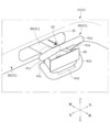
- FIG. 2 is a perspective view of the vehicle interior equipment, the operating unit, and the display unit inside the vehicle, showing the operating unit and the display unit in the "storage position.”
- FIG. 13 is a diagram showing the operation unit and the display unit in the "deployed position.”
- FIG. 13 is a diagram showing the operation unit and the display unit in the "storage position.”
- 13 is a diagram for explaining how the operation unit and the display unit are switched from the "storage position" to the "deployed position.”
- FIG. FIG. 13 is a diagram showing the operation unit and the display unit in the "deployed position.”
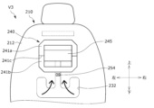
- FIG. 11 is a perspective view of a first vehicle seat, an operating unit, and a display unit of a vehicle according to a second embodiment, showing the operating unit and the display unit in a "storage position" state.
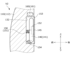
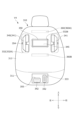
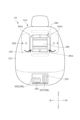
- FIG. 13 is a diagram showing the operation unit and the display unit in the "deployed position.” 1 is a side cross-sectional view of the first vehicle seat, showing the operation unit and the display unit in the "storage position.”
- FIG. FIG. 13 is a diagram showing the operation unit and the display unit in the "deployed position.”
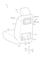
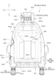
- FIG. 13 is a rear view of the first vehicle seat, the operating unit, and the display unit of the vehicle of the third embodiment, showing the operating unit and the display unit in the "storage position.”
- FIG. 13 is a rear view of the first vehicle seat, the operating unit, and the display unit of the vehicle of the third embodiment, showing the operating unit and the display unit in the "storage position.”
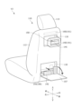
- FIG. 13 is a diagram showing the operation unit and the display unit in the "deployed position.”
- FIG. 2 is a side cross-sectional view of the first vehicle seat, showing the steering unit and the display unit in the "storage position.”
- FIG. 13 is a diagram showing the steering unit and display unit in the "deployed position.”
- FIG. 13 is a rear view of the first vehicle seat, the operating unit, and the display unit of the vehicle of the fourth embodiment, showing the operating unit and the display unit in the "storage position.”
- FIG. 13 is a diagram showing the operation unit and the display unit in the "deployed position.”
- FIG. 13 is a diagram illustrating a state in which the operation unit and the display unit are in the "storage position.” 13 is a diagram illustrating the state of the operation unit and the display unit in the "deployed position.”
- FIG. 1 is a side view of the first vehicle seat, showing the operation unit (steering unit, acceleration/deceleration operation unit) and the foot support member in the "storage position.”
- FIG. 1 is a diagram showing the steering unit, acceleration/deceleration operation unit, and foot support member in the "deployed position” state.
- FIG. 13 is a rear view of the first vehicle seat, the operating unit, and the display unit of the vehicle of the fifth embodiment, showing the operating unit and the display unit in the "storage position.”
- FIG. 13 is a diagram showing the operation unit and the display unit in the "deployed position.”
- FIG. 2 is a side cross-sectional view of the first vehicle seat, showing the steering unit and the display unit in the "storage position.”
- FIG. 13 is a diagram showing the steering unit and display unit in the "deployed position.”
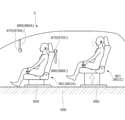
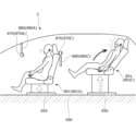
- 13 is a side view of a vehicle of a sixth embodiment, including a first vehicle seat, a second vehicle seat, an operating unit, and a display unit, the operating unit and the display unit being in the "deployed position.”
- FIG. FIG. 13 is a diagram illustrating the interior space of a vehicle according to a seventh embodiment.
- FIG. 23 is a top view of the vehicle of the eighth embodiment.
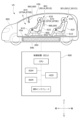
- FIG. 13 is an overall view of a vehicle seat system according to a ninth embodiment.
- FIG. 2 is a rear view of the vehicle seat showing the position of the imaging device.
- FIG. 11 is a rear view of the vehicle seat of the modified example, showing the position of the imaging device.
- 1 is a block diagram showing a hardware configuration and functions of a vehicle seat system.
- FIG. 2 is a side view of a vehicle seat, a display device, and an imaging device.
- FIG. 4 is a diagram showing an example of a display screen of a display device.
- FIG. 2 is a side view of a vehicle seat, a display device, and an imaging device.
- FIG. 4 is a diagram showing an example of a display screen of a display device.
- the first to eighth embodiments relate to a "vehicle” that enables more effective use of the interior space of the vehicle.
- the "front-rear direction of the vehicle” refers to the front-rear direction of the vehicle when it is normally running.
- the “inner side of the width of the vehicle” refers to the interior side of the vehicle (inside the vehicle) with respect to the vehicle door, and the “outer side of the width of the vehicle” refers to the exterior side of the vehicle (outside the vehicle) with respect to the vehicle door.
- the vehicle V1 is, for example, a vehicle (automobile) and is a vehicle (for example, an electric vehicle) equipped with two rows of vehicle seats 10, 20 in the front-to-rear direction of the vehicle V1.
- the vehicle V1 may be a vehicle equipped with three or four or more rows of vehicle seats.
- the vehicle V1 is a vehicle that can be driven by an occupant seated in the rear row of the vehicle seat 20.
- the driving operation unit 40 can be stored in the storage recess 32. This allows the occupant seated in the rear seat to effectively utilize the space inside the vehicle.
- the vehicle V1 is a vehicle that allows passengers seated in the rear row to drive the vehicle, and the rear seats serve as a cockpit (driver's seat, pilot's seat).
- the vehicle V1 comprises a vehicle body 1, a vehicle floor 2, a center console 3, a dashboard 4, a first vehicle seat 10, a second vehicle seat 20, a driver's operation console 30, a driver's operation unit 40, and a display unit 45.
- the vehicle V1 also includes switching members 50, 55 for switching between the driving operation unit 40 and the display unit 45, a plurality of airbag devices 60, and a driving control device .
- a driving control device 70 is attached inside the center console 3
- a front driving operation unit 5 is attached to the rear surface of the dashboard 4 .
- the vehicle body 1 corresponds to the vehicle body, and includes a side wall portion 1a that forms the side wall of the vehicle V1, a top wall portion 1b that forms the ceiling of the vehicle V1, a bottom wall portion 1c that forms the bottom wall of the vehicle V1, a front wall portion 1d, and a rear wall portion 1e.
- the vehicle floor 2 is a vehicle body floor for mounting a center console 3, a dashboard 4, vehicle seats 10, 20, a driver's control console 30, etc., and is disposed on the bottom wall portion 1c of the vehicle body 1.
- An area enclosed by the vehicle floor 2, the side wall 1a, the top wall 1b, the front wall 1d, and the rear wall 1e inside the vehicle V1 constitutes a cabin (internal space) of the vehicle V1. Occupants spend time inside the cabin while the vehicle V1 is traveling.
- a vehicle battery vehicle-mounted battery
- the vehicle battery is electrically connected to, for example, the drive device, various electric devices (electrical equipment devices), the control device, and the vehicle seats 10 and 20 of the vehicle V1, and supplies power to these devices.
- the first vehicle seat 10 is a seat that corresponds to a front seat, and is provided on the vehicle floor 2 and positioned slightly rearward of the dashboard 4 .
- An occupant seated in the first vehicle seat 10 can drive the vehicle V by operating a front driving operation unit 5 provided on the dashboard 4.
- the first vehicle seat 10 comprises a seat body having a seat cushion 11, a seat back 12 and a headrest 13, a rail device 15 for moving the seat body in the front-rear direction relative to the vehicle floor 2, a seat rotation device 16 for rotating the seat body around an axis along the up-down direction relative to the vehicle floor 2, a height link device 17 for raising and lowering the seat body relative to the vehicle floor 2, and a reclining device 18 for rotatably connecting the seat back 12 to the seat cushion 11.
- the seat cushion 11 is a seating portion that supports a seated person from below, and includes a cushion frame that serves as a skeleton, a padding material that is placed on the cushion frame, and a skin material that covers the cushion frame and the padding material.
- the seat back 12 is a backrest portion that supports a seated occupant from behind, and includes a back frame, a padding material, and a covering material.
- the headrest 13 supports the head of a seated occupant from behind.
- the occupant seated in the first vehicle seat 10 can turn around to face the occupant seated in the second vehicle seat 20 (rear seat) and come into contact with each other. In other words, the occupants can spend their time comfortably inside the cabin.
- the second vehicle seat 20 is a seat equivalent to a rear seat, and is provided on the vehicle floor 2 and positioned slightly rearward of the first vehicle seat 10 and the driver's operation console 30.
- An occupant seated in the second vehicle seat 20 can drive the vehicle V by operating a driving operation unit 40 provided on the driving operation console 30.
- the second vehicle seat 20 includes a seat body having a seat cushion 21, a seat back 22, and a headrest 23, a rail device 25, a seat rotation device 26, a height link device 27, and a reclining device 28.
- the driver's operation console 30 is disposed between the first vehicle seat 10 and the second vehicle seat 20 in the fore-and-aft direction, and is an interior component of a vehicle for mounting the driver's operation unit 40, the display unit 45, and the airbag device 60.
- the driver's console 30 is installed on the vehicle floor 2 and extends from the side wall portion 1 a of the vehicle body 1 toward the center of the center console 3 .
- the driving operation console 30 comprises an operation console main body 31, a storage recess 32 (storage section) formed in a concave shape on the rear surface of the operation console main body 31, and a storage recess 33 formed in a concave shape on the rear surface of the operation console main body 31 and positioned lower than the storage recess 32.
- airbag devices 60A (airbag 61A) and 60B (airbag 61A) are attached at different positions.
- the driving operation unit 40 is also referred to as a rear driving operation unit, as shown in FIGS. 1 to 4C, and is operated by an occupant seated in the second vehicle seat 20.
- the driving operation unit 40 includes a steering unit 41 (steering wheel) for steering the vehicle V1, and an acceleration/deceleration operation unit 42 (operation pedals) for controlling the acceleration and deceleration of the vehicle V1.
- the steering unit 41 is switchable between a "storage position” shown in FIG. 2 in which it is stored in the storage recess 32 of the driver's control console 30, and a “deployed position” shown in FIG. 3 in which it is deployed from the storage recess 32.
- the steering unit 41 is, for example, a foldable operating handle that is stored in the storage recess 32 in a folded state, and when unfolded from the storage recess 32, it expands vertically to form the shape of an operating handle that can be operated by the occupant.
- the steering section 41 has a first steering portion 41a and a second steering portion 41b that are divided into upper and lower portions, and a joint portion 41c that connects the first steering portion 41a and the second steering portion 41b.
- the acceleration/deceleration operation unit 42 is switchable between a “storage position” shown in FIG. 2 in which it is stored in the storage recess 33 of the driver's operation console 30, and a “deployed position” shown in FIG. 3 in which it is deployed from the storage recess 33.
- the acceleration/deceleration operation units 42 are, for example, an accelerator pedal and a brake pedal, and are arranged side by side on the left and right.
- the acceleration/deceleration operation unit 42 may be an organ pedal or a hanging pedal.
- the display unit 45 is a display that displays information related to the operation of the vehicle V, and is arranged near the steering unit 41 and stored in the storage recess 32 together with the steering unit 41.
- the display unit 45 displays information related to the operation of the vehicle V1, such as a speedometer, a tachometer, a fuel meter, etc., as well as the current position information of the vehicle V1, navigation information, etc.
- the steering unit 41 and the display unit 45 are switched by a switching member 50.
- the acceleration/deceleration operation unit 42 is switched by a second switching member 55.
- the switching member 50 is attached to the driver's operation console 30 (storage recess 32) and is a member for causing the steering unit 41 and the display unit 45 to protrude rearward from the storage recess 32.
- the switching member 50 allows the steering unit 41 and the display unit 45 to be pulled out (exposed) in front of the occupant seated in the second vehicle seat 20.
- the switching member 50 has a cylindrical first telescopic member 51 that is attached to the inside of the storage recess 32 and holds the steering section 41 in an extendable and contractible manner, and a second telescopic member 52 that is inserted into the first telescopic member 51 and holds the display section 45 in an extendable and contractible manner.
- the first telescopic member 51 has a structure that extends so as to cause the steering section 41 to protrude (project) rearward in the fore-and-aft direction of the vehicle V1.
- the second extendable member 52 has a structure that extends so as to cause the display unit 45 to protrude (project) rearward in the fore-and-aft direction of the vehicle V1.
- the extension/contraction members 51, 52 are connected to a drive unit (drive motor) not shown, and can perform extension/contraction operations by receiving a predetermined operation from the user and controlling the drive unit by the operation control device 70.
- the steering unit 41 may be biased in a deploying direction by a biasing spring (not shown). In this way, when the steering unit 41 is released from the state stored in the storage recess 32, it can be automatically deployed by being biased by the biasing spring, as shown in Figures 4A to 4C.
- the steering unit 41 and the display unit 45 are independently movable by the extendable members 51 and 52 and are stored in the storage recess 32 .
- the display unit 45 is disposed slightly rearward of the steering unit 41 and surrounded by the steering unit 41. This allows the occupant to operate the steering unit 41 while checking the display unit 45.
- a cutout portion 41d is formed at the rear end of each of the first steering portion 41a and the second steering portion 41b constituting the steering unit 41 to avoid interference with the display unit 45.
- the first telescopic member 51 is attached to the driver's operation console 30 so as to be rotatable about an axis along the extending direction of the first telescopic member 51. When the driver rotates the steering unit 41, the rotational motion can be transmitted to a gear box (steering gear box) (not shown).
- the second switching member 55 is attached to the driver's operation console 30 (the storage recess 33 ) and is a member for causing the acceleration/deceleration operation unit 42 to protrude rearward from the storage recess 33 .
- the second switching member 55 allows the acceleration/deceleration operation unit 42 to be pulled out (exposed) in front of the occupant seated in the second vehicle seat 20 .
- the second switching member 55 is attached to the inside of the storage recess 33 and has an extendable rod 56 that extends and retracts the acceleration/deceleration operation unit 42 .
- the telescopic rod 56 is connected to a drive unit (drive motor) not shown, and can perform telescopic motion by receiving a predetermined operation from the user and controlling the drive unit by the operation control device 70.
- a gear box not shown.
- the airbag device 60 includes airbag devices 60A and 60B each built into the driver's control console 30.
- the airbag device 60A is disposed on the driver's operation console 30 on the front side of the second vehicle seat 20, that is, on the front side of the occupant seated in the second vehicle seat 20.
- the airbag device 60A is disposed at a position slightly above the storage recess 32.
- the airbag device 60A is configured such that, when the vehicle V1 (drive control device 70) detects an external impact, the airbag 61A in a folded state inflates and deploys rearward. Therefore, a vehicle V1 can be realized that enables an occupant seated in the second vehicle seat 20 (rear seat) to perform driving operations and thereby improves safety technology during the driving operations.
- the airbag device 60B is disposed on the driver's operation console 30 on the side of the second vehicle seat 20, i.e., on the side (right side) of an occupant seated on the second vehicle seat 20. In other words, the airbag device 60B is disposed on the side wall portion 1a side of the vehicle V1.
- the airbag device 60B is configured so that when the vehicle V1 (driving control device 70) detects an external impact, the folded airbag 61B inflates and deploys from the outside to the inside in the width direction of the vehicle V1.
- the driving operation unit 40 and the airbag devices 60A, 60B are disposed at different positions on the driving operation console 30. Further, the airbag devices 60A, 60B are disposed at positions on the driver's operation console 30 that are different from the storage recess 32 . Therefore, the airbag devices 60A, 60B can be suitably disposed in the driver's operation console 30 so as not to interfere with other components.
- the driving control device 70 is an electronic control unit (ECU) that controls the driving of the vehicle V1, and performs overall electrical control within the vehicle V1.
- the driving control device 70 accepts a specified selection by the user and controls the front driving operation unit 5 and the driving operation unit 40 (rear driving operation unit) to switch between an "operable state” in which driving operation is possible, and an “inoperable state” in which driving operation is not possible.
- the driving control device 70 when the driving control device 70 receives a user's selection of the driving operation unit 40, the driving control device 70 places the front driving operation unit 5 in an "inoperable state” and controls the driving operation unit 40 to be switched to an "operable state”. Then, the driving control device 70 operates the switching members 50, 55 to switch the driving operation unit 40 and the display unit 45 from the "stored position (storage position)" to the "deployed position". In addition, by setting the driving operation unit 40 to the "operable state", the driving control device 70 causes the display unit 45 to display information regarding the driving of the vehicle V1.
- the driving control device 70 controls the front driving operation unit 5 to be in an "operable state” and switches the driving operation unit 40 to an "inoperable state”.
- the driving operation unit 40 and the display unit 45 are then held in the "stored position (stowed position)".
- the driving control device 70 when an external impact is detected by a detection sensor (not shown) and the driving control device 70 receives a detection signal from the detection sensor, it deploys the airbag of one of the multiple airbag devices 60A, 60B that corresponds to the switching position of the driving operation unit 40.
- the driving control device 70 may inflate and deploy the airbag devices 60A and 60B (or may deploy only the airbag device 60B).
- the driving control device 70 may inflate and deploy the airbag device 60B.
- the vehicle V1 may further include airbag devices other than the airbag devices 60A and 60B.
- the driving control device 70 may operate the switching members 50, 55 to switch the driving operation unit 40 from the “deployed position” to the “storage position (stored position)" when an external impact is detected by a detection sensor (not shown).
- vehicle V2 is equipped with a first vehicle seat 110, a second vehicle seat (not shown), a driving operation unit 140 (steering unit 141, acceleration/deceleration operation unit 142), a display unit 145, switching members 150, 155, a locking device 154, an airbag device 160, and a driving control device (not shown).
- the driving operation unit 140 is for a passenger seated in the second vehicle seat (rear seat) to drive and operate the vehicle, and corresponds to a rear driving operation unit.
- the first vehicle seat 110 corresponds to a front seat, and includes a seat cushion 111 , a seat back 112 , and a headrest 113 .
- the rear surface of the seat back 112 is formed with a recessed storage recess 132 and a recessed storage recess 133 disposed below the storage recess 132 .
- the steering unit 141 and the display unit 145 are stored in the storage recess 132.
- a cover 153 that covers the storage recess 132 is attached to an opening of the storage recess 132.
- the acceleration/deceleration operation unit 142 is stored in the storage recess 133.
- a plate-shaped foot support member 157 that covers the storage recess 133 is attached to an opening of the storage recess 133.
- An airbag device 160 (airbag 161 ) is attached inside the upper portion of the seat back 112 .
- the steering section 141 is switchable between a "storage position” in which it is stored in the storage recess 132 and a “deployed position” in which it is deployed from the storage recess 132.
- the steering unit 141 is, for example, a frame-shaped operating handle (operating steering wheel) and is deployed to a position protruding rearward from the storage recess 132.
- the acceleration/deceleration operation unit 142 can be switched between a "storage position” in which it is stored in the storage recess 133 and a “deployed position” in which it is deployed from the storage recess 133.
- the acceleration/deceleration operation unit 142 is, for example, an accelerator pedal and a brake pedal, and is arranged side by side on the left and right.
- the display unit 145 is a display, is disposed within the frame of the steering unit 141, and is stored in the storage recess 132 together with the steering unit 141.
- the steering unit 141 and the display unit 145 are switched by a switching member 150.
- the acceleration/deceleration operation unit 142 is switched by a second switching member 155.
- the switching member 150 has a link mechanism (multi-joint link mechanism) made up of a plurality of links 151 , and is attached to the storage recess 132 .
- the switching member 150 can move the steering unit 141 and the display unit 145 to the “storage position” by folding multiple links 151.
- the switching member 150 is fixed to the tip end (rear end) of the link 151 and has a plate-shaped holding member 152 that holds the steering unit 141 and the display unit 145.
- the holding member 152 is provided inside the steering section 141 and is connected to an inner surface in the width direction of the steering section 141.
- the holding member 152 is also connected to the rear surface of the display section 145.
- the link mechanism may be attached directly to the steering unit 141 or the display unit 145.
- the switching member 150 is connected to a drive unit (drive motor) not shown, and can perform an extension/contraction operation by receiving a predetermined operation from a user and controlling the drive unit by an operation control device.
- the switching member 150 is attached to the first vehicle seat 110 so as to be rotatable about an axis along the extension/retraction direction of the link mechanism. When the occupant rotates the steering unit 141, the rotational motion can be transmitted to a steering gear box (not shown).
- the cover 153 is, for example, a retractable shade (roll curtain) and is attached to the upper end of the opening of the storage recess 132 .
- the cover 153 can be switched between a "covered state” in which the cover 153 covers the storage recess 132 as shown in FIG. 7A and an "opened state” in which the cover 153 exposes the storage recess 132 as shown in FIG. 7B.
- an engaging member may be fixed to the tip of the cover 153, and an engaged member may be attached to the lower end of the opening of the storage recess 132. The engaging member and the engaged member are engaged with each other, whereby the cover 153 covers the storage recess 132.
- the locking device 154 is provided at the bottom of the storage recess 132 and is capable of holding the steering unit 141 stored in the storage recess 132 and locking the operation of the steering unit 141 .
- the locking device 154 may lock the steering section 141 by engaging with a notched portion (not shown) formed in the steering section 141 .
- the locking device 154 can be locked and unlocked under the control of an operation control device, or may be manually locked and unlocked.
- the second switching member 155 is attached to the inside of the storage recess 133, and has an extendable rod 156 that extends and retracts the acceleration/deceleration operation unit 142.
- the telescopic rod 156 is connected to a drive unit (drive motor) not shown, and can perform telescopic motion by receiving a predetermined operation from a user and controlling the drive unit by an operation control device.
- the foot support member 157 is rotatably attached to a lower portion of the first vehicle seat 110 (seat back 112) via a rotation shaft.
- the foot support member 157 can be switched between a "covered state” in which it covers the storage recess 133 and a “deployed state” in which it exposes the storage recess 133 and supports the feet of the occupant from below.
- the foot support members 157 extend rearwardly from the first vehicle seat 110 when in the "deployed" state shown in FIG.
- the airbag device 160 is provided at the upper end (upper portion) of the seat back 112, and is disposed in a position facing an occupant seated in the second vehicle seat (rear seat). Specifically, the airbag device 160 is disposed at a position slightly above the storage recess 132 . The airbag device 160 is configured so that, when the vehicle V2 detects an external impact, the airbag 161 in a folded state inflates and deploys rearward.
- the driving control device mounted inside the vehicle V2 When the driving control device mounted inside the vehicle V2 receives a selection of the driving operation unit 140 by the user, it operates the switching members 150, 155 to switch the driving operation unit 140 and the display unit 145 from the "storage position (stored position)" to the “deployed position.” It also causes the display unit 145 to display information related to the driving of the vehicle V2.
- the driving control device also controls the driving operation unit 140 to switch between an “operable state” and an “inoperable state”. When the driving operation unit 140 is in the “inoperable state”, the driving control device controls the locking device 154 to lock the driving operation unit 140 stored in the storage recess 132.
- a vehicle V3 of a third embodiment will be described with reference to FIGS. 8 to 10B. Note that explanations of the contents that overlap with those of the above-mentioned vehicles V1 and V2 will be omitted.
- vehicle V3 is equipped with a first vehicle seat 210, a second vehicle seat (not shown), a driving operation unit 240, a display unit 245, a switching member 250, a locking device 254, an airbag device 260, and a driving control device (not shown).
- the driving operation unit 240 is for a passenger seated in the second vehicle seat (rear seat) to drive and operate the vehicle, and corresponds to a rear driving operation unit.
- the first vehicle seat 210 is a seat equivalent to a front seat, and includes a seat back 212.
- a storage recess 232 having a recessed shape is formed on the rear surface of the seat back 212.
- the storage recess 232 stores the driving operation unit 240, the display unit 245, and the switching member 250.
- a cover 253 is attached to the opening of the storage recess 232.
- An airbag device 260 (airbag 261 ) is attached inside the upper portion of the seat back 212 .
- the driving operation unit 240 is switchable between a "storage position” in which it is stored in the storage recess 232 and a “deployed position” in which it is deployed from the storage recess 232.
- the driving operation unit 240 is a foldable operating handle, and in a folded state is stored in the storage recess 232. When unfolded from the storage recess 232, it unfolds vertically to become an operating handle that can be operated by the occupant.
- the driving operation unit 240 has a first steering portion 241a and a second steering portion 241b that are divided into upper and lower portions, and a joint portion 241c that connects the first steering portion 241a and the second steering portion 241b.
- the display unit 245 is a display that is disposed within the frame of the driving operation unit 240 and is stored in the storage recess 232 together with the driving operation unit 240.
- the driving operation unit 240 and the display unit 245 are switched by a switching member 250 .
- the switching member 250 has a link mechanism 251 (multi-joint link mechanism), and is attached to the storage recess 232 and stored in the storage recess 232.
- the switching member 250 can be rotated rearward so as to rise from the seat back 212, thereby moving the driving operation unit 240 and the display unit 245 to the "deployed position".
- the switching member 250 is fixed to the rear end of the link mechanism 251 and has a plate-shaped holding member 252 that holds the driving operation unit 240 and the display unit 245.
- the holding member 252 is provided within the frame of the driving operation unit 240, and is connected to an inner surface in the width direction of the driving operation unit 240.
- the holding member 252 is also connected to the rear surface of the display unit 245.
- the switching member 250 is attached to be rotatable around an axis along the front-rear direction with respect to the first vehicle seat 210. When the occupant rotates the driving operation unit 240, the rotational motion can be transmitted to a steering gear box (not shown).
- the cover 253 is, for example, a backboard, and is detachably attached to the seat back 212.
- the locking device 254 is provided at the bottom of the storage recess 232, and is capable of locking the driving operation unit 240 stored in the storage recess 232. Specifically, the locking device 254 engages with the switching member 250 (link mechanism 251) to lock the engagement.
- the airbag device 260 is provided at the upper end (upper portion) of the seat back 212, and is disposed in a position facing an occupant seated in the second vehicle seat (rear seat).
- the airbag device 260 is disposed at a position slightly above the storage recess 232 .
- a vehicle can be realized that can effectively utilize the interior space. Specifically, when a passenger sitting in the rear seat is not performing driving operations, the passenger can effectively utilize the space around the rear seat.
- a vehicle V4 of a fourth embodiment will be described with reference to FIGS. 11 to 14B.
- explanations of the contents that overlap with those of the above-mentioned vehicles V1 to V3 will be omitted.
- vehicle V4 is equipped with a first vehicle seat 310, a second vehicle seat 320, a driving operation unit 340 (steering unit 341, acceleration/deceleration operation unit 342), a display unit 345, switching members 350, 355, a locking device 354, a moving device 358, an airbag device 360, and a driving control device 370.
- the driving operation unit 340 is for an occupant seated in the second vehicle seat 320 (rear seat) to drive and operate the vehicle, and corresponds to a rear driving operation unit.
- the first vehicle seat 310 is a seat equivalent to a front seat, and includes a seat cushion 311 and a seat back 312.
- the rear surface of the seat back 312 is formed with recessed storage recesses 332A, 332B and a storage recess 333 having a recessed shape.
- the left and right storage recesses 332A store a steering unit 341.
- the storage recess 332B stores a display unit 345.
- the acceleration/deceleration operation unit 342 is stored in the storage recess 333.
- a plate-shaped foot support member 357 and a movement device 358 that supports the foot support member 357 are provided slightly below the storage recess 333.
- Airbag devices 360A, 360B are attached inside the upper and lower portions of the seat back 312.
- the steering section 341 is switchable between a "storage position” in which it is stored in the storage recess 332A and a “deployed position” in which it is deployed from the storage recess 332A.
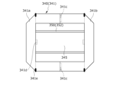
- the steering unit 341 is a foldable operating handle that is stored in the storage recess 332A in a folded state and is removable from the storage recess 332.
- the steering section 341 has a first steering portion 341a and a second steering portion 341b divided into left and right portions, a joint portion 341c connecting the first steering portion 341a and the second steering portion 341b, and a connection portion 341d for connecting to the switching member 350 (holding member 352).
- Each of the first steering portion 341a and the second steering portion 341b has a rotating portion 341e and is further capable of rotating between a folded state and an unfolded state.
- the steering section 341 is held by a locking device 354 provided at the bottom of the storage recess 332A.
- the locking device 354 clamps the divided steering portion 341a (341b) and locks the steering portion 341a.
- the acceleration/deceleration operation unit 342 can be switched between a "storage position" stored in the storage recess 333 and a “deployed position” deployed from the storage recess 333.
- the display unit 345 is a display that is disposed within the frame of the steering unit 341 and is stored in the storage recess 332B separately from the steering unit 341.
- the display unit 345 is held by a switching member 350 (holding member 352).
- the switching member 350 has an expandable member 351 that expands and contracts the display unit 345, and a plate-shaped holding member 352 that is fixed to the rear end of the expandable member 351 and holds the display unit 345.
- the holding member 352 is provided within the frame of the steering section 341, and is connected to an inner surface in the width direction of the steering section 341.
- the holding member 352 is also connected to the rear surface of the display section 345.
- the switching member 350 is attached to the first vehicle seat 310 so as to be rotatable about an axis along the front-rear direction. When the occupant rotates the steering unit 341, the rotational motion can be transmitted to a steering gear box (not shown).
- the second switching member 355 is attached to the inside of the storage recess 333, and has an extendable rod 356 that extends and retracts the acceleration/deceleration operation unit 342.
- the foot support member 357 is supported by a moving device 358 .
- the foot support member 357 can be switched between a "storage position” in which it is stored within the first vehicle seat 310 and a "support position” in which it protrudes rearward from the first vehicle seat 310 and supports the occupant's feet from below.
- the foot support members 357 extend from the first vehicle seat 310 towards the second vehicle seat 320 when in the "support position" shown in Figure 14B.
- the foot support member 357 has an engaging member 357 a that is engageable with an engaged portion 320 a provided on the second vehicle seat 320 .
- the foot support member 357 may be provided on the second vehicle seat 320 instead of the first vehicle seat 310. In that case, the foot support member 357 may extend from the second vehicle seat 320 toward the first vehicle seat 310. In other words, the foot support member 357 may be configured in the reversed front-to-back direction.
- the moving device 358 is, for example, a slide rail device, and includes a fixed rail 358a that extends along the front-rear direction of the first vehicle seat 310, and a slider 358b that is slidably attached to the fixed rail 358a and supports the foot support member 357.
- a vehicle can be realized that can effectively utilize the interior space. Specifically, when a passenger sitting in the rear seat is not performing driving operations, the passenger can effectively utilize the space around the rear seat.
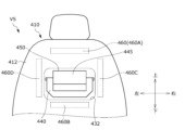
- a vehicle V5 of a fifth embodiment will be described with reference to FIGS. 15 to 17B.
- explanations of the contents that overlap with those of the above-mentioned vehicles V1 to V4 will be omitted.
- vehicle V5 is equipped with a first vehicle seat 410, a second vehicle seat (not shown), a driving operation unit 440, a display unit 445, a switching member 450, an airbag device 460, and a driving control device (not shown).
- the driving operation unit 440 is for a passenger seated in the second vehicle seat (rear seat) to drive and operate the vehicle, and corresponds to a rear driving operation unit.
- the first vehicle seat 410 is a seat equivalent to a front seat, and includes a seat back 412.
- a storage recess 432 having a recessed shape is formed on the rear surface of the seat back 412.
- the storage recess 432 stores a driving operation unit 440 and a display unit 445 .
- Airbag devices 460 A, 460 B, 460 C, and 460 D are attached to the rear surface of the seat back 212 so as to surround the driving operation unit 440 and the display unit 445 .
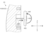
- the driving operation unit 440 is switchable between a "storage position” in which it is stored in the storage recess 432 and a “deployed position” in which it is deployed from the storage recess 432.
- the driving operation unit 440 is a foldable operating handle, and in a folded state is stored in the storage recess 432. When unfolded from the storage recess 432, it unfolds vertically to become an operating handle that can be operated by the occupant.
- the driving operation unit 440 has a first steering portion 441a and a second steering portion 441b that are divided into upper and lower portions, and a joint portion 441c that connects the first steering portion 441a and the second steering portion 441b.
- the display unit 445 is a display that is disposed within the frame of the driving operation unit 440 and is stored in the storage recess 432 together with the driving operation unit 440 .
- the switching member 450 has an expandable member 451 that expands and contracts the driving operation unit 440 and the display unit 445, and a plate-shaped holding member 452 fixed to the rear end of the expandable member 451.
- the holding member 452 is provided within the frame of the driving operation unit 440, and is connected to an inner side surface in the width direction of the driving operation unit 440.
- the holding member 452 is also connected to the rear surface of the display unit 445.
- a vehicle can be realized that can effectively utilize the interior space. Specifically, when a passenger sitting in the rear seat is not performing driving operations, the passenger can effectively utilize the space around the rear seat.
- vehicle V6 is equipped with a first vehicle seat 510 (front seat), a second vehicle seat 520 (rear seat), a driving operation unit 540, a switching member 550, a rotating device 519 for rotating the armrest, an ottoman device 529, and a driving control device 570.
- the driving operation unit 540 is for an occupant seated in the second vehicle seat 520 to drive and operate the vehicle, and corresponds to a rear driving operation unit.
- the driving operation unit 540 has a steering unit 541 , an acceleration/deceleration operation unit 542 , and an operation acceptance unit 543 .
- the rotating device 519 and the ottoman device 529 correspond to a second switching member.
- the first vehicle seat 510 includes a seat cushion 511, a seat back 512, an armrest 514 attached to the seat back 512, and a rotation device 519 that rotatably connects the armrest 514 to the seat back 512.
- the armrest 514 can be switched by the rotation device 519 between a "standard position” for use by an occupant seated in the first vehicle seat 510 and an "extended position” in which the armrest 514 rotates rearward from the "standard position” for use by an occupant seated in the second vehicle seat 520.
- An operation acceptance unit 543 (operation button) for driving operations is provided on the bottom surface of the armrest 514. When the armrest 514 is in the "deployed position", the operation acceptance unit 543 is located on the top surface of the armrest 514 as shown in FIG.
- the second vehicle seat 520 comprises a seat cushion 521, a seat back 522, a movable member 529a attached to the tip of the seat cushion 521 and supporting the occupant's feet from below, and an ottoman device 529 that rotatably connects the movable member 529a to the seat cushion 521.
- the ottoman device 529 is a device that moves a movable member 529a back and forth between a "storage position” and an "expanded position" around a rotation shaft 529b at the tip of the seat cushion 521 as the center of rotation.
- the movable member 529a is stored on the seat cushion 521 side (the bottom surface of the seat cushion 521) when in the "storage position", and is protruded toward the front side of the seat when in the "deployed position".
- an acceleration/deceleration operation unit 542 and a foot support member 557 that supports the feet (heels) of the occupant are attached to the upper surface of the movable member 529a. Providing the foot support member 557 can prevent the occupant's feet from slipping.
- the switching member 550 is attached to the rear surface of the seat back 512 and causes the steering portion 541 to protrude rearward from the seat back 512.
- the switching member 550 allows the steering section 541 to be extended in front of an occupant seated in the second vehicle seat 520.
- the ottoman device 529 can be pulled out to the feet of the occupant by switching the movable member 529a, the acceleration/deceleration operation unit 542, and the foot support member 557 from the “storage position” to the “deployed position” shown in FIG.
- the rotation device 519 can switch the armrest 514 from the "standard position” to the "extended position” shown in FIG. 18, so that the armrest 514 can be pulled out to the passenger's hand.
- the driving control device 570 accepts a predetermined selection by the user and controls the rotation device 519, the ottoman device 529, and the switching member 550 to switch to the "deployed position" shown in FIG. 18. It also controls the steering unit 541, the acceleration/deceleration operation unit 542, and the operation acceptance unit 543 to switch from the "inoperable state” to the "operable state.”
- a vehicle can be realized that can effectively utilize the interior space. Specifically, when a passenger sitting in the rear seat is not performing driving operations, the passenger can effectively utilize the space around the rear seat.
- the vehicle V7 includes a vehicle body 601, a vehicle floor 602, a center console 603, a dashboard 604, a first vehicle seat 610 (front seat), a second vehicle seat (rear seat) (not shown), and a driving operation unit 640.
- the vehicle V7 also includes switching members 650 and 655, and a driving control device 670.
- a display unit 606 capable of displaying vehicle information and an imaging unit 607 capable of capturing images of the interior of the vehicle are attached to the connecting portion of the top wall portion 601b and the front wall portion 601d of the vehicle body 601.
- a storage section 603a and an in-vehicle information display section 603b are attached to the rear surface of the center console 603.
- Another in-vehicle information display section 603b is attached to the top surface of the center console 603.
- a driving control device 670 is attached inside the center console 603.
- a storage recess 604a is formed on the rear surface of the dashboard 604.
- the front driving operation unit 605 is stored in the storage recess 604a and can be protruded from the storage recess 604a.
- the first vehicle seat 610 includes a seat cushion 611 , a seat back 612 , a headrest 613 , and an armrest 614 .
- a storage recess 632 and a storage recess 633 disposed below the storage recess 632 are formed on the rear surface of the seat back 612 .
- a steering unit 641 is stored in the storage recess 632, and an acceleration/deceleration operation unit 642 is stored in the storage recess 633.
- an in-vehicle component operating unit 643 and a display unit 645 are attached to the rear surface of the seat back 612 .
- a cutout 613a is formed on the inner side of the headrest 613 in the width direction. Therefore, a passenger sitting in the rear seat can see the face of a passenger sitting in the front seat through the cutout 613a.
- a transparent member may be provided instead of the cutout 613a.
- the steering section 641 can be switched by a switching member 650 between a "storage position” and a “deployed position” in which it protrudes rearward from the storage position.
- the acceleration/deceleration operation unit 642 can be switched by a second switching member 655 between a "storage position” and a “deployed position” in which it protrudes rearward from the storage position.
- the driving control device 670 accepts a predetermined selection by the user and performs control so as to change the display contents of the in-vehicle information display unit 603b and the display unit 606.
- the driving control device 670 also controls the switching members 650, 655 to switch between the "storage position (stored position)" and the "deployed position”. It also controls the steering unit 641, the acceleration/deceleration operation unit 642, and the in-vehicle component operation unit 643 to switch from the "inoperable state" to the "operable state”.
- a vehicle can be realized that can effectively utilize the interior space. Specifically, when a passenger sitting in the rear seat is not performing driving operations, the passenger can effectively utilize the space around the rear seat.
- Vehicle V8 includes a vehicle body 701, a vehicle floor 702, a center console 703, a dashboard 704, a first vehicle seat 710, a second vehicle seat 720, a driver's control console 730, operation units 705, 740, and a display unit 745 (indoor equipment).
- the vehicle V1 also includes a switching member 750 for switching the operation unit 740, a driving control device 770, a projection device 780, and a goggle device 790 (wearable device).
- the display unit 745 is a large display screen (indoor equipment) that is disposed in the front part of the vehicle body 701 and can be pulled out from the ceiling wall of the vehicle body 701.
- the display unit 745 may be pulled out from the vehicle floor 702.
- An operation control device 770 is attached inside the center console 703 , and a projection device 780 (projector) is attached to the upper surface of the center console 703 .
- the projection device 780 is disposed behind the display unit 745 and is capable of projecting an image onto the display unit 745 .
- the goggle device 790 is, for example, virtual reality goggles (VR goggles), and is worn by a passenger (on the passenger's face) seated in the vehicle seats 710, 720.
- the operation units 705 and 740 are for operating the display contents projected on the display unit 745, and are operated by the occupant.
- the passenger can enjoy playing virtual reality games, for example, by operating the operation units 705, 740 (operation controllers) while wearing the goggle device 790 (VR goggles).
- a vehicle can be realized that can effectively utilize the interior space. Specifically, when a passenger sitting in the rear seat is not performing driving operations, the passenger can effectively utilize the space around the rear seat.
- the driving operation console 30, the first vehicle seat 10, and the second vehicle seat 20 are provided on the vehicle body 1.
- the first vehicle seat 10 is disposed in front of the driving operation console 30, and the second vehicle seat 20 is disposed in the rear of the driving operation console 30.
- a storage recess 32 (storage section) is formed in the driving operation console 30, and a driving operation section 40 for operating the vehicle V1 is stored in the storage recess 32.
- the driving operation unit 40 be configured so as to be switchable between the "storage position" and the "deployed position” by a switching member 50 provided on the driving operation console 30.
- the driving operation unit 40 (steering unit 41) has a shape of an operating handle, but this is not particularly limited.
- the shape of the driving operation unit 40 may be a cockpit type or a lever type.
- the driving operation unit 40, 140 is stored on the rear surface of the driving operation platform 30 or the first vehicle seat 110, but this is not particularly limited.
- the driving operation units 40, 140 may be detached and stored in an armrest or a center console.
- the driving operation units 40, 140 may be detached and installed in all the seats, and the occupants may be seated in the designated seats and drive the vehicle V1.
- a car was described as a specific example, but the invention is not limited to this and can be used for vehicles such as trains, buses, airplanes, ships, etc.
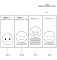
- the vehicle seat system S is a device that is mounted on a vehicle V9 and moves a part or the whole of a vehicle seat 801 (seat body 801a) in which a passenger sits, based on the passenger's facial expression.
- the system can arrange the seat configuration of the vehicle seat 801 so that the passenger can spend more comfortably inside the vehicle V9, for example, as shown in Figs. 25 to 28.
- the entertainment value inside the vehicle V9 can be increased.
- the vehicle seat system S recognizes the facial expression of an occupant seated in the vehicle seat 801. Then, based on the recognition information, it determines the type of facial expression of the occupant (e.g., a smile, etc.).
- the vehicle seat system S includes a plurality of vehicle seats 801 each arranged inside the vehicle V9, a plurality of imaging devices 870, a plurality of display devices 880, a plurality of audio acquisition devices 885, a plurality of vibration devices 890, a collision detection sensor 895, and a control device 900.
- the vehicle V9 is a vehicle (automobile).
- the vehicle seat 801 includes a front seat 801A (driver's seat), a front seat 801B (passenger's seat), a rear seat 801C, and a rear seat 801D.
- Each vehicle seat 801 comprises a seat body 801a having a seat cushion 810, a seat back 820 and a headrest 830, a slide rail device 840 that supports the seat body 801a so that it can move back and forth relative to the vehicle floor V9a, a height device 850 that connects the seat body 801a to the vehicle floor V9a so that it can be raised and lowered, and a reclining device 860 that connects the seat back 820 to the seat cushion 810 so that it can be rotated.
- the seat cushion 810, the seat back 820, and the headrest 830 correspond to a seat body 801a.
- the slide rail device 840, the height device 850, and the reclining device 860 correspond to a movable device.
- the cushion frame 811 comprises left and right side frames 811a arranged on the sides in the seat width direction, a plate-shaped pan frame 811b connecting the front portions of each side frame 811a, a pipe-shaped rear connecting frame 811c connecting the rear portions of each side frame 811a, and a number of elastic springs 811d that are hooked onto the pan frame 811b and the rear connecting frame 811c, respectively, and extend in a snake-like shape.
- the seat back 820 is a backrest portion that supports a seated occupant from behind, and includes a back frame 821 that serves as a skeleton, a padding material 822 , and a covering material 823 .
- the back frame 821 is made of a rectangular frame-like body that serves as the framework of the seat back 820 .
- the back frame 821 comprises a side frame 821a arranged laterally in the seat width direction, an inverted U-shaped upper frame 821b connecting the upper end portions of each side frame 821a, a plate-shaped lower frame 821c connecting the lower end portions of each side frame 821a, a plate-shaped connecting frame 821d connecting the upper portions of each side frame 821a, a plurality of wire members 821e hooked to the connecting frame 821d and the lower frame 821c, and a support plate 821f held by the plurality of wire members 821e and supporting an occupant.
- Left and right pillar guides 821g are fixed at a predetermined distance from each other in the widthwise central portion of the upper frame 821b.
- a reclining device 860 is attached to the connecting portion of the cushion frame 811 and the back frame 821
- a slide rail device 840 is attached to the lower portion of the cushion frame 811 via a height device 850 .
- the headrest 830 is a head portion that supports the head of an occupant from behind, and includes a pillar 831 that serves as a core material, a pad material 832 , and a cover material 833 .
- the pillar 831 is held by left and right pillar guides 821g.
- An imaging device 870 (imaging camera) is fixed to the rear surface of the headrest 830 (pillar 831).
- the slide rail device 840 is attached between the seat cushion 810 and the vehicle floor V9a in the vertical direction.
- the slide rail device 840 is fixed to the vehicle floor V9a and comprises left and right lower rails 841 extending in the fore-and-aft direction of the seat, left and right upper rails 842 supported slidably along the lower rails 841, a locking member 843 that locks the upper rails 842 against the lower rails 841 so that they cannot slide, and a rail operating lever (not shown) that releases the locked state of the locking member 843.
- a seat cushion 810 (cushion frame 811 ) is attached to the upper surfaces of the left and right upper rails 842 via a height device 850 .
- the height device 850 is attached between the slide rail device 840 and the seat cushion 810, as shown in FIGS.
- the height device 850 includes left and right first links 851 arranged on the front side of the seat, left and right second links 852 arranged on the rear side of the seat, a locking member 853 that locks the seat cushion 810 so that it cannot be raised or lowered, and a height operating lever (not shown) that releases the locked state of the locking member 853.
- the height device 850 can adjust the height of the seat cushion 810 by using the second link 852 as a driving link, for example.
- the reclining device 860 includes a reclining body 861 that is driven to rotate the seat back 820, a back rotation shaft 862, a spiral spring 863 that urges the seat back 820 to rotate forward around the back rotation shaft 862, and a reclining operation lever (not shown) that releases the locked state of the seat back 820.
- the reclining body 861 has a known locking mechanism, and the state of the seat back 820 can be switched between a "locked state” in which it is fixed to the seat cushion 810, and an “unlocked state” in which it can be rotated relative to the seat cushion 810.
- the back rotation shaft 862 is supported in the seat width direction on the seat cushion 810 side and the seat back 820 side.
- One end of the spiral spring 863 is anchored to the seat cushion 810 side, and the other end is anchored to the seat back 820 side.
- the imaging device 870 is a small camera (wide-angle camera) that captures an image of an occupant (the occupant's face) seated in the vehicle seat 801 .
- the imaging device 870 captures an image of the occupant, generates “imaging data”, and transmits the “imaging data” to the control device 900 .
- the imaging device 870 may be an imaging camera equipped with AI (artificial intelligence) and capable of analyzing captured images.
- the imaging device 870 may also be a 360-degree omnidirectional camera (a camera equipped with a fisheye lens), etc.
- the imaging devices 870 are disposed at positions corresponding to the front seat 801A, the front seat 801B, the rear seat 801C, and the rear seat 801D. Specifically, the imaging devices 870A and 870B are attached to the ceiling V9b and disposed in front of the front seats 801A and 801B, respectively. The imaging devices 870C and 870D are attached to the rear surfaces of the front seats 801A and 801B, respectively, and disposed in front of the rear seats 801C and 801D. More specifically, the imaging device 870C (870D) is attached to the rear surface of the headrest 830 of the front seat 801A (801B) via a cover member 834. It is possible to appropriately change the number and mounting positions of the image capturing devices 870. For example, as shown in FIG 23, a plurality of image capturing devices 870 may be mounted on one vehicle seat 801.
- FIG. 23 is a rear view of a modified vehicle seat 801.
- imaging devices 871 to 876 are attached to the rear surface of the vehicle seat 801.
- the imaging device 871 is attached to the upper end of the headrest 830 via a cover member 834 , and is disposed at a position higher than the imaging device 870 .
- the imaging device 872 is attached to the rear surface of the upper frame 821b, and is exposed rearward from the vehicle seat 801.
- the imaging devices 873 are attached to the left and right side portions of the upper frame 821b, and are exposed rearward from the vehicle seat 801.
- the imaging device 874 is attached to the center of the connecting frame 821d and is exposed rearward from the vehicle seat 801.
- the imaging device 870 can be arranged compactly within the vehicle V9.
- a vibration suppression device that suppresses vibration of the imaging device 870 may be provided in the portion of the vehicle seat 801 where the imaging device 870 is attached or in the surrounding area thereof. In this way, blurring of the image obtained by the imaging device 870 can be suppressed.
- the vibration suppression device may be, for example, a gimbal device or an elastic member.
- the elastic member may be, for example, a spring or a vibration-damping sponge (soft foam having low resilience). Alternatively, it may be a variable damping type damper that utilizes air pressure, hydraulic pressure, or an oil syringe (viscous material).
- the voice acquisition device 885 is a device that acquires the voice of an occupant seated in the vehicle seat 801, and is, for example, a microphone, a voice recorder, or the like.
- the voice acquisition device 885 acquires the voice of the occupant, generates “voice data”, and transmits the “voice data” to the control device 900 .
- the voice acquisition devices 885 are disposed at positions corresponding to the front seat 801A, the front seat 801B, the rear seat 801C, and the rear seat 801D.
- the voice acquisition device 885 may be mounted inside the display device 880. In other words, it may be configured as a part of the display device 880.
- the vehicle seat system S may further include a sound generating device (speaker) that generates a predetermined sound or music for an occupant seated in the vehicle seat 801 .
- the vehicle seat system S may further include an execution sensor (execution switch) for executing image capture by the image capture device 870.
- the execution sensor may be disposed on an interior member of the vehicle or on the outer surface of the vehicle seat. For example, an occupant can press and operate the execution sensor to capture an image by the image capture device 870.
- a control process using the captured image data described below may be performed to select the occupant with the most smile among the multiple occupants, and operate the vehicle seat 801 in which the occupant is seated.
- the smile of the occupant may be displayed on the display device 880.
- the control device 900 is a device that performs overall electrical control of the vehicle V9, and is, for example, an engine control unit (ECU).
- the control device 900 is connected to the slide rail device 840, the height device 850, the reclining device 860, the imaging device 870, the display device 880, the voice acquisition device 885, the vibration device 890 and the collision detection sensor 895 via an in-vehicle network.
- the control device 900 is a computer equipped with a CPU (processor) as a data calculation/control processing device, ROM and RAM as storage devices, a HDD, and a communication interface for sending and receiving information data via the in-vehicle network.
- the storage device of the control device 900 stores a vehicle seat program according to this embodiment in addition to a main program that performs the necessary functions of a computer.
- the functions of the vehicle seat system S are realized when this program is executed by the CPU (processor).
- the control device 900 mainly comprises a memory unit 910 for storing various programs and various data, a facial expression recognition unit 911, a facial expression judgment unit 912, a calculation unit 913, a movable amount determination unit 914, a movement control unit 915, an output unit 916, and a physical information detection unit 917.
- a CPU processor
- ROM read only memory
- RAM random access memory
- HDD hard disk drive
- communication interface various programs, and the like.
- the storage unit 910 stores "imaging data,”"audiodata,””occupant physique data,””movement amount data,” etc.
- Imaging data and "occupant physique data” are data obtained from the imaging device 870
- audio data is data obtained from the audio acquisition device 885, and are stored in a centralized manner.
- “Movement amount data” is data indicating the amount of movement of the movable devices 840, 850, 860, and is stored in a centralized manner.
- the control device 900 can move the movable devices 840, 850, 860 in response to the facial expression, voice, and physique of each occupant.
- the storage unit 910 also stores criteria data such as "facial expression criteria data” and "degree of change criteria data” which will be described later.
- the facial expression recognition unit 911 recognizes the facial expression of an occupant seated in the vehicle seat 801 . Specifically, the facial expression recognition unit 911 acquires "imaging data" captured by the imaging device 870, recognizes the facial expression of the occupant based on the "imaging data", and acquires "recognition information relating to facial expression”. More specifically, the facial expression recognition unit 911 detects position information of components of the face of the occupant and angle information indicating the tilt angle of the head based on the "imaging data”. Then, based on the position information and angle information, it obtains recognition information regarding the facial expression.
- the above recognition information includes, for example, information on the movements of lowering eyebrows, lifting outer eyebrows, lifting cheeks, lifting chin, making dimples, closing eyes, opening eyes, lifting inner eyebrows, lowering chin and opening lips, tensing eyelids, lifting corners of lips, pressing lips, pursing lips, pulling corners of lips sideways, sucking in lips, opening mouth, wrinkling nose, lifting upper lip, and blinking. It also includes information on up and down, left and right, and tilting movements of the head.
- the facial expression determination unit 912 determines the type of facial expression of the occupant (for example, whether the occupant is smiling) based on the recognition information by the facial expression recognition unit 911 . Specifically, the facial expression determination unit 912 determines the type of facial expression of the occupant and the degree of change in the facial expression (the magnitude of the facial expression) based on the above recognition information. For example, the facial expression determination unit 912 determines a "smile” as the predetermined facial expression of the occupant, and evaluates the "size of the smile" as the degree of change in the smile into multiple levels (multiple stages), and presents the evaluation level. A higher evaluation level indicates a greater change in facial expression. It is preferable that the storage unit 910 stores "facial expression reference data" for determining the type of facial expression of the occupant and "degree of change reference data" for determining the degree of change in a predetermined facial expression.
- the facial expression determination unit 912 may determine the type of facial expression of the occupant as a "smile", or may determine a surprised face, a happy face, a fearful face, a sad face, an angry face, a contemptuous face, or a blank face.
- the calculation section 913 calculates the number of times a predetermined facial expression has been determined by the facial expression determination section 912 . Specifically, the calculation unit 913 calculates the number of times a predetermined facial expression (for example, a smile) is determined by the facial expression determination unit 912 within a predetermined time period. The calculation unit 913 determines that a smile has occurred once when the smile exceeds a first reference time. In this case, the calculation unit 913 may determine that a smile has occurred twice when the smile continues to exceed a second reference time, and may determine that a smile has occurred three times when the smile continues to exceed a third reference time. The calculation unit 913 may calculate the time during which a smiling expression is made (the time during which it is made continuously) within a predetermined period of time.
- a predetermined facial expression for example, a smile
- the movement amount determination unit 914 determines the amount of movement of the vehicle seat 801 (seat body 801 a ) based on the number of times the predetermined facial expression (smile) is determined as calculated by the calculation unit 913 . Specifically, the movement amount determination unit 914 determines the movement amount of the movable device (the amount of rise of the height device 850) based on the number of times a smile is determined. The movement amount determination unit 914 may determine the movement amount of the height device 850 based on the number of times a smile is determined and the degree (magnitude) of change in the smile.
- the movement amount determination unit 914 may determine a larger movement amount (1.5 times or 2 times the movement amount) when the degree of the smile is large when the smile is determined (when the evaluation level is higher than normal). Alternatively, the movement amount determination unit 914 may determine a smaller movement amount (0.5 times the movement amount) when the degree of the smile is small when the smile is determined (when the evaluation level is lower than normal).
- the operation control unit 915 controls the operation of the movable device based on the determination information by the facial expression determination unit 912 . Specifically, the operation control unit 915 controls the operation of the movable devices 840, 850, 860 based on the movable amount of the seat body determined based on the determination information by the facial expression determination unit 912 and the information of the calculation result by the calculation unit 913. In other words, the operation control unit 915 moves a predetermined movable device based on the movable amount determined by the movable amount determination unit 914.
- the operation control unit 915 may control the seat body to return to the "reference position" after a predetermined time has elapsed after moving a part or the whole of the seat body from the "reference position (position where an occupant can sit)" to the "first movement position". In other words, the operation control unit 915 may move the seat body continuously from the "first movement position” to the "second movement position", or may move the seat body from the "reference position” to the "second movement position".
- the facial expression recognition unit 911 recognizes the facial expressions of a plurality of occupants. Then, the facial expression determination unit 912 determines the smile and the size of the smile for each occupant based on the above recognition information. Then, the operation control unit 915 raises the height device 850 so as to move the vehicle seat 801 in which a specific occupant is seated, based on the smile of each occupant and the size of the smile of each occupant.
- the height device 850 is not operating in the right front seat 801A, whereas the height device 850 is raising the seat body in the right rear seat 801C.
- a display screen shown in Fig. 26, which will be described later, is displayed on the display device 880.
- information related to the seat states of the vehicle seats 801A to 801D and information related to the facial expressions (smile, degree of smile, number of smiles) of the occupants corresponding to the vehicle seats 801A to 801D are displayed in conjunction with each other.
- the control device 900 controls the height device 850 to raise the seat body. This allows passengers to compete with each other, improving entertainment value.
- the control by the operation control unit 915 may be executed as shown in FIG. 27 and FIG.
- the facial expression recognition unit 911 recognizes the facial expressions of a plurality of occupants.
- the facial expression determination unit 912 determines the smile and the size of the smile for each occupant based on the above recognition information.
- the operation control unit 915 raises the height device 850 and the reclining device 860 so as to move the vehicle seat 801 in which a specific occupant is seated, based on the smile of each occupant and the size of the smile (number of times the occupant smiles).
- the height device 850 raises the seat body
- the height device 850 raises the seat body
- the reclining device 860 moves the seat body rearward.
- the display screen shown in Fig. 28 is displayed on the display device 880.
- information related to the seat states of the vehicle seats 801A to 801D and information related to the facial expressions (smile, size of smile, number of smiles) of the occupants corresponding to the vehicle seats 801A to 801D are displayed.
- the height device 850 and the reclining device 860 are controlled to move. This can improve entertainment value.
- the operation control unit 915 also acquires "occupant voice data" obtained by the voice acquisition device 885, and controls the operation of the vibration device 890 based on the volume of the occupant's voice. In this way, it can be recognized that the passenger is laughing out loud by the vibration operation of the vibration device 890. At this time, the vibration device 890 of the vehicle seat 801 in which the passenger is seated may be operated, or the vibration devices 890 of multiple vehicle seats 801 may be operated. In this way, it is possible to increase the entertainment value inside the vehicle.
- the operation control unit 915 may control the movable device (height device 850) to move the seat body based on the occupant's smile determined by the facial expression determination unit 912 and the volume of the occupant's voice obtained by the voice acquisition device 885. By doing so, it is possible to more accurately determine whether the occupant is laughing, and to operate the movable device based on the determination result. Specifically, the following applies: The movement amount determination unit 914 multiplies the movement amount of the movable device by a predetermined coefficient based on the voice data (volume of voice) obtained by the voice acquisition device 885.
- the movement amount determination unit 914 increases the movement amount when the voice of the occupant is louder than a predetermined voice reference value, and decreases the movement amount when the voice is quieter than the voice reference value.
- the movement amount determination unit 914 (which may be called the laughter determination unit) determines whether the occupant's voice is a "normal voice” or a "laughing voice", and if it determines that the voice is a "laughing voice", it multiplies the movement amount of the movable device (reference movement amount) by a predetermined coefficient (laughing voice coefficient).
- the movement amount determination unit 914 may make the determination based on the voice waveform data.
- the movement control unit 915 moves the movable devices 840 , 850 , and 860 based on the movement amount determined by the movement amount determination unit 914 .
- the operation control unit 915 controls the movable devices 840, 850, and 860 not to operate, regardless of the judgment information by the facial expression judgment unit 912 (the amount of movement determined by the amount of movement determination unit 914). In this way, operation of movable devices 840, 850, 860 can be stopped if a collision of vehicle V9 is predicted or if vehicle V9 has collided.
- the output unit 916 outputs first display information in which the facial expression of the occupant determined by the facial expression determination unit 912 is converted into a character's facial expression, and second display information based on the operation information of the movable device controlled by the operation control unit 915.
- the first display information is, for example, as shown in Fig. 26 and Fig. 28.
- the facial expression of each passenger is converted into the facial expression of a character (face mark) and is displayed. Specifically, it can be seen that the passenger sitting in the right rear seat 801C is smiling.
- the second display information is as shown in FIG. 26 (FIG. 28), for example. The number of times that each occupant has been determined to have a smile is counted and displayed.
- the number of times that the occupant seated in the right rear seat 801C has been determined to have a smile is three (four). Since the amount of movement of the movable device is determined based on the number of times that a smile has been determined, this is equivalent to information based on the operation of the movable device being displayed. In other words, it can be seen that the right rear seat 801C has a larger amount of movement than the right front seat 801A and the left front seat 801B.
- the output unit 916 outputs display information in which the character's facial expression is changed based on the change in the passenger's facial expression determined by the facial expression determination unit 912 .
- the character may be a facial mark, an avatar that pays homage to the face of a passenger, or an animal.
- the number of times a smile has been determined may be displayed by the number of cushions, or by the character's movements (the character gradually standing up).
- the physique information detection unit 917 detects physique information of the occupant seated in the vehicle seat 801 .
- the physique information detection unit 917 measures the length of the upper body, the length of the thighs, and the length of the lower legs as physique information of the occupant based on the image data of the occupant, and then detects mainly the position of the head of the occupant.
- the operation control unit 915 controls the operation of the movable devices 840, 850, 860 based on the physique information of the occupant obtained by the physique information detection unit 917, and moves the seat body so that the seat position corresponds to the imaging range of the imaging device 870. This makes it easier for the imaging device 870 to recognize the facial expression (smile) of the occupant.
- the operation control unit 915 controls the height device 850 so as to limit the lifting and lowering operation of the seat body based on the physique information of the occupant. In this way, the operation of the height device 850 can be limited based on the physique information of the occupant, allowing the occupant to sit comfortably.
- the operation control unit 915 limits the rise of the height device 850 so that the top of the occupant's head falls within the imaging range.
- the operation control unit 915 operates the reclining device 860 so that the occupant's facial expression is easily detected by the imaging device 870 (front position).
- the operation control unit 915 limits the ascent of the height device 850 based on the occupant's physique so that the head does not come into contact with the ceiling V9b of the vehicle V9.
- the operation control unit 915 controls the height device 850 so that the occupant's head falls within the imaging range, and adjusts the height of the seat body.
- the operation control unit 915 may control the height device 850 of the vehicle seat 801C on which the occupant sits in response to the movement, and further adjust the height of the seat body.
- the slide rail device 840 and the reclining device 860 may also be operated together. This makes it easier to recognize the facial expression (smile) of the occupant.
- the program of this embodiment is a program for realizing the above-mentioned facial expression recognition unit 911, facial expression determination unit 912, calculation unit 913, movable amount determination unit 914, motion control unit 915, output unit 916, and physique information detection unit 917 as functional components of a control device 900 having a storage unit 910.
- the CPU (processor) of the control device 900 executes this vehicle seat program.
- the program is executed, for example, when triggered by the acceptance of an instruction to start the system S through an operation by an occupant (user).
- step 1 the facial expression recognition unit 911 recognizes the facial expression of an occupant seated in the vehicle seat 801. Specifically, the facial expression recognition unit 911 acquires "imaging data” captured by the imaging device 870, recognizes the facial expression of the occupant based on the "imaging data”, and acquires "recognition information relating to facial expression”.
- the facial expression determination unit 912 determines the type of facial expression of the occupant (for example, whether the occupant is smiling) based on the recognition information by the facial expression recognition unit 911. Specifically, the facial expression determination unit 912 determines the type of facial expression of the occupant and the magnitude of the facial expression based on the above recognition information.
- step 3 the calculation unit 913 calculates the number of times a smile has been determined by the facial expression determination unit 912 . Specifically, the calculation unit 913 calculates the number of times a smile has been determined by the facial expression determination unit 912 within a predetermined period of time.
- the movement amount determination unit 914 determines the movement amount of the vehicle seat 801 based on the number of times a smile has been determined as calculated by the calculation unit 913 . Specifically, the movement amount determination unit 914 determines the movement amount of the movable device based on the number of times a smile is determined. As described above, the movement amount determination unit 914 may determine the movement amount of the movable device based on the number of times a smile has been determined and the size of the smile.
- the output unit 916 outputs first display information in which the facial expression of the occupant determined by the facial expression determination unit 912 is converted into a facial expression of the character, and second display information based on the operation information of the movable device controlled by the operation control unit 915.
- the second display information can also be said to be information based on the number of times a smile has been determined and the size of the smile. Specifically, the display screen is as shown in FIG.
- step 7 the control device 900 determines whether or not a request to stop the vehicle seat system S has been received through an operation by the occupant. If a request to stop the system S has been received (step 7: Yes), the process in FIG. 30 ends. On the other hand, if a request to stop the system S has not been received (step 7: No), the process returns to step 1 and the above process is repeated.
- the vehicle seat system and vehicle seat program described above make it possible to control the operation of a movable device based on the occupant's biometric information (e.g., the occupant's facial expression). It also makes it possible for the occupant seated in the vehicle seat to feel comfortable inside the vehicle.
- biometric information e.g., the occupant's facial expression
- the vehicle seat system S may, as a simple control, recognize the facial expression of an occupant seated in the vehicle seat 801, and when a predetermined facial expression of the occupant (the occupant's smile) is determined, control the operation of a predetermined movable device (height device 850).
- the vehicle seat system S may recognize the facial expression of an occupant seated in the vehicle seat 801 to determine whether the occupant is smiling, and may control the height device 850 to operate when the occupant's voice is recognized.
- the vehicle seat system S may be configured to include a vehicle seat 801, an imaging device 870, a voice acquisition device 885, a lighting device that adjusts the brightness inside the vehicle, and a control device 900 that controls these devices.
- the control device 900 may change the illumination color of the lighting device and perform imaging by the imaging device 870 according to the volume of the passenger's voice acquired by the voice acquisition device 885. This allows passengers to be photographed with natural expressions and also reduces energy consumption due to lighting.
- the system S may determine the passenger who is the loudest among the passengers, adjust the lighting at the seat where the passenger is seated, and capture the image. This allows the lighting to highlight the passenger who talks a lot, and allows the passenger's natural facial expression to be captured.
- the system S may further include a voice recording device (voice recording function) for recording the voices of the passengers.
- voice recording function voice recording function
- the system S may control the operation of the imaging device 870 attached to the rear surface of the seat back 820 based on the posture of the seat body (seat back 820). By doing so, the angle of view of the imaging device 870 (imaging camera) can be appropriately maintained in accordance with the posture of the seat body.
- the imaging device 870 is disposed at a position on the rear surface that does not overlap with the driving operation part. In this way, it is possible to capture images without interfering with the driving operation part.
- a vehicle seat system for use in an automobile has been described as a specific example, but the vehicle seat system is not limited to this and can be used in vehicles such as trains, buses, airplanes, ships, etc.
- the vehicle seat system includes a vehicle seat having a seat body on which an occupant can sit and a movable device that moves part or all of the seat body, and a control device that controls the operation of the movable device, and the control device preferably has an expression recognition unit that recognizes the expression of an occupant seated in the vehicle seat, an expression determination unit that determines the type of expression of the occupant based on recognition information by the expression recognition unit, and an operation control unit that controls the operation of the movable device based on determination information by the expression determination unit.
- the control device of this system recognizes the facial expression of the occupant, determines the type of facial expression of the occupant based on the recognition information, and controls the operation of the movable device based on the determination information.
- the operation of the seat movable device can be controlled according to the type of facial expression (change in facial expression) of the occupant. Therefore, the seat configuration of the vehicle seat can be arranged so that the occupant can spend more comfortably inside the vehicle. It can also improve entertainment value.
- the facial expression recognition unit recognizes the facial expressions of multiple occupants
- the facial expression determination unit determines the degree of change in facial expression for each occupant based on the recognition information for each occupant
- the operation control unit controls the movable device to move the seat body in which a specified occupant is seated based on the type of facial expression for each occupant and the degree of change in facial expression determined by the facial expression determination unit.
- the vehicle seat is provided with an imaging device that images an occupant seated in the vehicle seat
- the control device has a physique information detection unit that detects physique information of the occupant
- the operation control unit controls the operation of the movable device based on the physique information of the occupant from the physique information detection unit, and moves the seat body so that the seating position corresponds to the imaging range of the imaging device.
- the vehicle is provided with a display device used by an occupant seated in a vehicle seat
- the control device has an output unit that outputs first display information in which the occupant's facial expression determined by the facial expression determination unit is converted into a character's facial expression, and second display information based on operation information of the movable device controlled by the operation control unit, and the display device displays the first display information and the second display information output by the output unit toward the occupant.
- a predetermined facial expression e.g., a smile
- the amount of movement of the movable device can be displayed.
- the control device is provided with a display device used by an occupant seated in the vehicle seat, and has a calculation unit that calculates the number of times a predetermined facial expression has been determined by the facial expression determination unit, and an output unit that outputs display information based on the number of times the predetermined facial expression has been determined by the calculation unit, and the display device displays the display information output by the output unit toward the occupant.
- a predetermined facial expression e.g., a smile
- This improves entertainment value. For example, a smile can be quantified, which improves entertainment value.
- the control device has a calculation unit that calculates the number of times a specified facial expression is determined by the facial expression determination unit, and a movement amount determination unit that determines the amount of movement of the seat body based on the number of times the specified facial expression is determined by the calculation unit, and the operation control unit controls the movable device based on the amount of movement of the seat body determined by the movement amount determination unit, and moves the seat body.
- the movable device can be moved based on the number of times the occupant makes a specified facial expression (e.g., smiling), and other occupants can tell that the occupant is smiling from the amount of movement of the movable device.
- a voice acquisition device for acquiring the voice of an occupant seated in the vehicle seat, and the operation control unit controls the movable device to move the seat body based on the smiling facial expression of the occupant determined by the facial expression determination unit and the degree of the occupant's voice acquired by the voice acquisition device.
- a voice acquisition device is provided for acquiring the voice of an occupant seated in the vehicle seat
- a vibration device is provided for imparting vibrations to the occupant seated in the vehicle seat
- the operation control unit controls the operation of the vibration device based on the level of the occupant's voice acquired by the voice acquisition device.
- a collision detection unit that detects a vehicle collision, and when the collision detection unit detects a vehicle collision, the operation control unit controls the movable device not to operate regardless of the determination information by the facial expression determination unit.
- the movable device is a height device that connects the seat body to the vehicle floor so that it can be raised and lowered
- the control device has a physique information detection unit that detects physique information of an occupant seated in the vehicle seat
- the operation control unit controls the height device to restrict the raising and lowering movement of the seat body based on the occupant's physique information.
- the vehicle and the vehicle seat system according to the present invention have been mainly described.
- the above embodiment is merely an example for facilitating understanding of the present invention, and is not intended to limit the present invention.
- the present invention can be modified or improved without departing from the spirit of the present invention, and the present invention naturally includes equivalents thereof.
- Vehicle Vehicle body (car body) 1a Side wall portion 1b Top wall portion 1c Bottom wall portion 1d Front wall portion 1e Rear wall portion 2 Vehicle floor (vehicle floor) 3 Center console 4 Dashboard 5 Front driving operation section (front operation section) 10 First vehicle seat (first vehicle seat) 11 seat cushion 12 seat back 13 headrest 15 rail device 16 seat rotation device 17 height link device 18 reclining device 20 second vehicle seat (second vehicle seat) 21 seat cushion 22 seat back 23 headrest 25 rail device 26 seat rotation device 27 height link device 28 reclining device 30 driver's console (vehicle interior equipment) 31 Operation table body 32 Storage recess (storage section) 33 Storage recess (storage section) 40 Driving operation unit (operation unit, rear driving operation unit) 41 Steering section (operating handle) 41a: First steering portion; 41b: Second steering portion; 41c: Joint portion; 41d: Cutout portion; 42: Acceleration/deceleration operation portion (operation pedal); 45 Display unit 50 Switching member 51 First telescopic
Landscapes
- Engineering & Computer Science (AREA)
- Health & Medical Sciences (AREA)
- Mechanical Engineering (AREA)
- Life Sciences & Earth Sciences (AREA)
- Transportation (AREA)
- Aviation & Aerospace Engineering (AREA)
- General Health & Medical Sciences (AREA)
- Public Health (AREA)
- Veterinary Medicine (AREA)
- Animal Behavior & Ethology (AREA)
- Surgery (AREA)
- Molecular Biology (AREA)
- Medical Informatics (AREA)
- Heart & Thoracic Surgery (AREA)
- Physics & Mathematics (AREA)
- Biomedical Technology (AREA)
- Biophysics (AREA)
- Pathology (AREA)
- Dentistry (AREA)
- Oral & Maxillofacial Surgery (AREA)
- Chemical & Material Sciences (AREA)
- Psychiatry (AREA)
- Hospice & Palliative Care (AREA)
- Educational Technology (AREA)
- Combustion & Propulsion (AREA)
- Child & Adolescent Psychology (AREA)
- Developmental Disabilities (AREA)
- Physiology (AREA)
- Psychology (AREA)
- Social Psychology (AREA)
- Seats For Vehicles (AREA)
- Fittings On The Vehicle Exterior For Carrying Loads, And Devices For Holding Or Mounting Articles (AREA)
Abstract
Description
本発明は、乗り物に係り、特に、複数の乗り物用シートを備えた乗り物に関する。 The present invention relates to vehicles, and in particular to vehicles equipped with multiple vehicle seats.
従来、車両の内部に設けられる第1の車両用シート(前席)と、車両の内部に設けられ、第1の車両用シートよりも後方位置に配置される第2の車両用シート(後席)と、第1の車両用シートの後面に取り付けられ、車両の運転を操作する運転操作部(操作ハンドル)と、を備えた車両が知られている(例えば、特許文献1参照)。 Conventionally, a vehicle is known that includes a first vehicle seat (front seat) provided inside the vehicle, a second vehicle seat (rear seat) provided inside the vehicle and positioned rearward of the first vehicle seat, and a driving operation unit (operating handle) attached to the rear of the first vehicle seat and used to operate the vehicle (see, for example, Patent Document 1).
特許文献1に記載の車両では、第1の車両用シートと、第2の車両用シートと、第1の車両用シートに着座する乗員が操作する第1操作レバーと、第2の車両用シートに着座する乗員が操作する第2操作レバーと、第1操作レバー及び第2操作レバーの一方の運転操作を有効とする切替スイッチと、を備えている。
The vehicle described in
ところで、特許文献1のような車両において、車両の内部空間をより有効に活用することが可能な技術が求められていた。
例えば、第2の車両用シート(後席)に着座する乗員が運転操作を行わない場合に、当該乗員が第2の車両用シート周辺におけるスペースを有効に活用できることが求められていた(車内のスペースを制限されないことが求められていた)。
However, in vehicles such as the one described in
For example, when an occupant sitting in the second vehicle seat (rear seat) is not performing driving operations, it was required that the occupant be able to effectively utilize the space around the second vehicle seat (it was required that the space inside the vehicle not be restricted).
本発明の目的は、乗り物の内部空間をより有効に活用することが可能な乗り物を提供することにある。
本発明の他の目的は、後席に着座する乗員が運転操作を行わない場合に、当該乗員が後席周辺におけるスペースを有効に活用することが可能な乗り物を提供することにある。
An object of the present invention is to provide a vehicle that can utilize the interior space of the vehicle more effectively.
Another object of the present invention is to provide a vehicle that allows an occupant seated in the rear seat to effectively utilize the space around the rear seat when the occupant is not performing driving operations.
前記課題は、本発明の乗り物によれば、乗り物の内部に設けられる第1の乗り物用シートと、前記乗り物の内部に設けられ、前記第1の乗り物用シートよりも後方位置に配置される第2の乗り物用シートと、前記第1の乗り物用シートの後面に取り付けられ、又は前記第1の乗り物用シート及び前記第2の乗り物用シートの間の位置にある乗り物用内装品に取り付けられ、前記乗り物又は前記乗り物の室内機器を操作する操作部と、を備え、前記操作部は、前記第1の乗り物用シートの後面に設けられた格納部に格納可能に取り付けられ、又は前記乗り物用内装品に設けられた格納部に格納可能に取り付けられること、により解決される。
上記構成により、乗り物の内部空間をより有効に活用可能な乗り物を実現することができる。
詳しく述べると、上記乗り物では、操作部が、第1の乗り物用シートの後面に取り付けられ、又は第1の乗り物用シート及び第2の乗り物用シートの間の位置にある乗り物用内装品に取り付けられている。そして、操作部は、第1の乗り物用シートの後面に設けられた格納部に格納可能に取り付けられ、又は乗り物用内装品に設けられた格納部に格納可能に取り付けられている。
そのため、例えば第2の乗り物用シート(後席)に着座する乗員が操作部を操作しない場合には、当該操作部を格納部に格納することができる。すなわち、乗員が第2の乗り物用シート周辺におけるスペースを有効に活用できる。
The above problem is solved by a vehicle of the present invention, which comprises a first vehicle seat provided inside the vehicle, a second vehicle seat provided inside the vehicle and positioned rearward of the first vehicle seat, and an operating unit attached to the rear surface of the first vehicle seat or to a vehicle interior accessory located between the first vehicle seat and the second vehicle seat, and which operates the vehicle or indoor equipment of the vehicle, wherein the operating unit is storably attached to a storage section provided on the rear surface of the first vehicle seat, or storably attached to a storage section provided on the vehicle interior accessory.
With the above configuration, a vehicle can be realized that can utilize the interior space of the vehicle more effectively.
More specifically, in the above-mentioned vehicle, the operating unit is attached to the rear surface of the first vehicle seat or to a vehicle interior accessory located between the first vehicle seat and the second vehicle seat, and is storably attached to a storage section provided on the rear surface of the first vehicle seat or to a storage section provided on the vehicle interior accessory.
Therefore, for example, when an occupant sitting in the second vehicle seat (rear seat) does not operate the operating unit, the operating unit can be stored in the storage section, which allows the occupant to effectively utilize the space around the second vehicle seat.
このとき、前記第1の乗り物用シートは、シートクッションと、前記シートクッションに取り付けられるシートバックと、を備え、前記操作部は、前記シートバックの後面に設けられた前記格納部に格納され、前記格納部に格納された格納位置と、前記格納部から展開され、乗員が運転操作するための展開位置との間で切り替え可能となっていると良い。
上記構成により、第2の乗り物用シートに着座する乗員が操作部を操作しない場合には、第2の乗り物用シートの後面に操作部を格納することができる。
In this case, the first vehicle seat includes a seat cushion and a seat back attached to the seat cushion, and the operating unit is stored in the storage section provided on the rear surface of the seat back and is switchable between a storage position stored in the storage section and a deployment position deployed from the storage section for an occupant to operate the vehicle while driving.
With the above-described configuration, when an occupant seated in the second vehicle seat does not operate the operating unit, the operating unit can be stored on the rear surface of the second vehicle seat.
このとき、前記操作部は、前記乗り物の操舵を行う操舵部と、前記乗り物の加減速を操作する加減速操作部と、を備え、前記操舵部は、前記シートバックの後面に凹状に形成された前記格納部としての格納凹部に格納され、前記加減速操作部は、前記第1の乗り物用シートの後面に凹状に形成され、前記格納凹部よりも下方位置に配置された収納凹部に収納されていると良い。
上記構成により、第2の乗り物用シートに着座する乗員が運転操作を行わない場合には、操舵部(例えば操作ハンドル)及び加減速操作部(例えば操作ペダル)を格納凹部に格納することができる。
In this case, the operating unit includes a steering unit that steers the vehicle and an acceleration/deceleration operating unit that controls the acceleration and deceleration of the vehicle, and the steering unit is stored in a storage recess that serves as the storage unit and is formed in a concave shape on the rear surface of the seat back, and the acceleration/deceleration operating unit is stored in a storage recess that is formed in a concave shape on the rear surface of the first vehicle seat and is positioned lower than the storage recess.
With the above configuration, when an occupant seated in the second vehicle seat is not performing driving operations, the steering unit (e.g., the operating handle) and the acceleration/deceleration operating unit (e.g., the operating pedals) can be stored in the storage recess.
このとき、前記操作部は、前記格納部に格納された格納位置と、前記格納部から展開され、乗員が運転操作するための展開位置との間で切り替え可能に設けられ、前記第1の乗り物用シート又は前記乗り物用内装品に取り付けられ、前記操作部を前記格納位置と前記展開位置の間で切り替える切り替え部材を備え、前記切り替え部材は、複数のリンクからなるリンク機構を有し、前記複数のリンクを折り畳むことで前記操作部を前記格納位置へと移動させると良い。
上記構成により、切り替え部材を動作させて操作部を「格納位置」と「展開位置」で切り替えることができる。また、リンク機構によって操作部をコンパクトに格納することができる。
In this case, the operating unit is provided so as to be switchable between a storage position stored in the storage section and a deployed position deployed from the storage section for an occupant to operate the vehicle, and is equipped with a switching member that is attached to the first vehicle seat or the vehicle interior accessory and switches the operating unit between the storage position and the deployed position, and the switching member has a link mechanism consisting of a plurality of links, and the operating unit is moved to the storage position by folding the plurality of links.
With the above-described configuration, the operating unit can be switched between the "storage position" and the "deployed position" by operating the switching member. In addition, the operating unit can be stored compactly by the link mechanism.
このとき、前記操作部は、前記乗り物の操舵を行う操舵部を備え、前記操舵部の近傍位置に配置され、前記乗り物の運転に関する情報を表示する表示部をさらに備え、前記操舵部、前記表示部は、前記格納部に格納可能に取り付けられ、前記操舵部と前記表示部とが、それぞれ独立して可動し、前記格納部へと格納されると良い。
上記構成により、操舵部及び表示部をそれぞれ独立して可動させて格納部へと格納することができる。
In this case, the operating unit includes a steering unit that steers the vehicle, and further includes a display unit that is arranged in the vicinity of the steering unit and displays information related to the operation of the vehicle, and the steering unit and the display unit are attached so as to be able to be stored in the storage unit, and the steering unit and the display unit are each movable independently and stored in the storage unit.
With the above configuration, the steering unit and the display unit can be moved independently and stored in the storage unit.
このとき、前記操舵部、前記表示部は、前記第1の乗り物用シートの後面又は前記乗り物用内装品に凹状に形成された前記格納部としての格納凹部に格納され、前記第1の乗り物用シートの後面又は前記乗り物用内装品に取り付けられ、前記格納凹部を覆うカバーが取り付けられ、前記カバーは、前記格納凹部を露出させた状態と、前記格納凹部を覆った状態とに切り替えられ、前記操舵部、前記表示部が前記格納凹部に格納された状態で前記格納凹部を覆うと良い。
上記構成により、操舵部及び表示部を使用しない場合には、操舵部及び表示部を格納部に格納させてカバーで覆うことができ、第2の乗り物用シート周辺における内部空間を好適にアレンジすることができる。
In this case, the steering unit and the display unit are stored in a storage recess formed in a concave shape as the storage unit in the rear surface of the first vehicle seat or in the vehicle interior accessory, and a cover is attached to the rear surface of the first vehicle seat or the vehicle interior accessory and covers the storage recess, and the cover is switched between a state in which the storage recess is exposed and a state in which the storage recess is covered, so that the steering unit and the display unit are stored in the storage recess and the storage recess is covered.
With the above configuration, when the steering unit and the display unit are not in use, the steering unit and the display unit can be stored in the storage unit and covered with a cover, allowing the internal space around the second vehicle seat to be arranged optimally.
このとき、前記操作部は、後方運転操作部であって、前記格納部に設けられ、前記格納部に前記後方運転操作部を格納させた状態で前記後方運転操作部の可動をロックするロック装置と、前記第1の乗り物用シートの前方位置に取り付けられ、前記乗り物の運転を操作する前方運転操作部と、前記乗り物の運転を制御する運転制御部と、を備え、前記運転制御部は、ユーザ操作の選択を受け付けて前記前方運転操作部、前記後方運転操作部それぞれを運転操作可能な操作可能状態と、運転操作不能な操作不能状態とに切り替えるように制御し、前記後方運転操作部が前記操作不能状態であるとき、前記格納部に格納された前記後方運転操作部をロックするように前記ロック装置を制御すると良い。
上記構成により、運転制御部は、第2の乗り物用シートに着座する乗員が運転操作を行わない場合に、後方運転操作部を格納部に格納させた状態でロックできる。そのため、乗員が前方運転操作部によって運転操作を行う場合には、第2の乗り物用シート周辺において内部空間をより有効に活用できる(後方運転操作部を格納させた状態で保持することができる)。
In this case, the operating unit is a rear driving operation unit that is provided in the storage unit and includes a locking device that locks the movement of the rear driving operation unit when the rear driving operation unit is stored in the storage unit, a front driving operation unit that is attached to a front position of the first vehicle seat and operates the driving of the vehicle, and a driving control unit that controls the driving of the vehicle, and the driving control unit accepts a user operation selection and controls each of the front driving operation unit and the rear driving operation unit to switch between an operable state in which it can be driven and an inoperable state in which it cannot be driven, and when the rear driving operation unit is in the inoperable state, controls the locking device to lock the rear driving operation unit stored in the storage unit.
With the above configuration, the driving control unit can lock the rear driving operation unit in a stored state in the storage unit when the occupant seated in the second vehicle seat is not performing driving operations, and therefore, when the occupant performs driving operations using the front driving operation unit, the internal space around the second vehicle seat can be more effectively utilized (the rear driving operation unit can be kept in a stored state).
このとき、前記第1の乗り物用シート及び前記第2の乗り物用シートの一方の下方部分に設けられ、前記第2の乗り物用シートに着座した乗員の足を下方から支持する足支持部材を備え、前記足支持部材は、前記第1の乗り物用シートに設けられた前記加減速操作部よりも下方位置に配置され、前記第1の乗り物用シート及び前記第2の乗り物用シートの前記一方から他方に向かって延びていると良い。
上記のように足支持部材を備えることで、第2の乗り物用シートに着座した乗員が足支持部材を利用しながら加減速操作部(操作ペダル)を好適に操作することができる。
In this case, a foot support member is provided in a lower portion of one of the first vehicle seat and the second vehicle seat, supporting the feet of an occupant seated on the second vehicle seat from below, and the foot support member is preferably positioned below the acceleration/deceleration operating unit provided on the first vehicle seat and extends from one of the first vehicle seat and the second vehicle seat to the other.
By providing the foot support member as described above, an occupant seated in the second vehicle seat can conveniently operate the acceleration/deceleration operation unit (operation pedal) while using the foot support member.
このとき、前記足支持部材を前記第1の乗り物用シート及び前記第2の乗り物用シートの前記一方から前記他方に向かって移動可能に支持する移動装置を備え、前記足支持部材は、前記第1の乗り物用シート及び前記第2の乗り物用シートの前記他方に設けられた被係合部に係合可能な係合部材を有していると良い。
上記構成により、第2の乗り物用シートに着座する乗員が操作部(加減速操作部)を操作しない場合には、足支持部材を引っ込めておくことができる。また、上記乗員が操作部を操作する場合には、足支持部材を引き出した状態で固定できる。
In this case, it is preferable that a moving device is provided that supports the foot support member so that it can be moved from one of the first vehicle seat and the second vehicle seat to the other, and that the foot support member has an engaging member that can engage with an engaged portion provided on the other of the first vehicle seat and the second vehicle seat.
With the above-mentioned configuration, when the occupant seated in the second vehicle seat does not operate the operating unit (acceleration/deceleration operating unit), the foot support member can be retracted, and when the occupant operates the operating unit, the foot support member can be fixed in the extended state.
このとき、前記乗り物の内部に設けられる複数のエアバッグ装置と、前記乗り物の運転を制御する運転制御部と、を備え、前記操作部は、前記格納部に格納された格納位置と、前記格納部から展開され、乗員が運転操作するための展開位置との間で切り替え可能に設けられ、前記運転制御部は、前記乗り物が外部からの衝撃を検出したとき、前記複数のエアバッグ装置のうち、前記操作部の切り替え位置に応じたエアバッグ装置のエアバッグを展開させると良い。
上記構成により、運転制御部は、操作部の切り替え位置(格納位置、展開位置)に応じたエアバッグ装置を作動させることができ、エアバッグを好適に膨出展開させることができる。すなわち、第2の乗り物用シート(後席)に着座する乗員が運転操作を行うにあたって、当該運転操作時における安全技術をより高めることができる。
In this case, the vehicle is provided with a plurality of airbag devices provided inside the vehicle, and a driving control unit that controls the driving of the vehicle, and the operating unit is provided so as to be switchable between a storage position stored in the storage unit and a deployment position deployed from the storage unit for an occupant to operate the vehicle, and when the vehicle detects an external impact, the driving control unit deploys an airbag of an airbag device among the plurality of airbag devices that corresponds to the switching position of the operating unit.
With the above configuration, the driving control unit can operate the airbag device according to the switching position (storage position, deployment position) of the operation unit, and can inflate and deploy the airbag appropriately. In other words, when an occupant sitting in the second vehicle seat (rear seat) performs driving operations, the safety technology during the driving operations can be further improved.
このとき、前記操作部、前記エアバッグは、前記第1の乗り物用シートのシートバックの後面において異なる位置に配置され、又は、前記乗り物用内装品において異なる位置に配置されていると良い。
また、前記エアバッグは、前記第1の乗り物用シートのシートバックの後面において前記格納部とは異なる位置に配置され、又は、前記乗り物用内装品において前記格納部とは異なる位置に配置されていると良い。
上記構成により、第1の乗り物用シートの後面において、又は乗り物用内装品において他の構成部品と干渉しないように、エアバッグを好適に配置することができる。また、後席に着座する乗員が運転操作を行うにあたって、安全技術をより高められる。
In this case, it is preferable that the operating unit and the airbag are disposed at different positions on a rear surface of a seat back of the first vehicle seat, or are disposed at different positions in the vehicle interior accessory.
In addition, the airbag may be disposed at a position on the rear surface of the seat back of the first vehicle seat that is different from the storage portion, or may be disposed at a position in the vehicle interior accessory that is different from the storage portion.
With the above-mentioned configuration, the airbag can be appropriately positioned on the rear surface of the first vehicle seat or in the vehicle interior so as not to interfere with other components, and the safety technology can be further improved when a passenger sitting in the rear seat performs driving operations.
このとき、前記室内機器は、前記乗り物に関する情報を表示する表示部であって、前記操作部は、前記表示部の表示内容を操作すると良い。
上記構成により、操作部によって表示部の表示内容を操作できる。
In this case, the indoor device may be a display unit that displays information about the vehicle, and the operation unit may operate the display content of the display unit.
With the above configuration, the display content of the display unit can be operated by the operation unit.
本発明によれば、乗り物の内部空間をより有効に活用可能な乗り物を実現できる。具体的には、第2の乗り物用シート(後席)に着座する乗員が操作部を操作しない場合には、当該操作部を格納部に格納できる。すなわち、乗員が第2の乗り物用シート周辺におけるスペースを有効に活用できる。
また本発明によれば、第2の乗り物用シートに着座する乗員が運転操作しない場合には、操舵部(操作ハンドル)及び加減速操作部(操作ペダル)を格納凹部に格納できる。
また本発明によれば、切り替え部材によって操作部を「格納位置」と「展開位置」で切り替えできる。また、リンク機構によって操作部をコンパクトに格納できる。
また本発明によれば、操舵部及び表示部を独立して可動させて格納部へと格納できる。
また本発明によれば、操舵部及び表示部を格納部に格納させてカバーで覆うことができ、第2の乗り物用シート周辺における内部空間を好適にアレンジできる。
また本発明によれば、乗員が前方操作部によって運転操作する場合には、第2の乗り物用シート周辺において内部空間をより有効活用できる(後方運転操作部を格納させた状態で保持できる)。
また本発明によれば、第2の乗り物用シートに着座した乗員が足支持部材を利用しながら加減速操作部(操作ペダル)を好適に操作できる。
また本発明によれば、乗員が操作部を操作しない場合には、足支持部材を引っ込めておくことができる。また、乗員が操作部を操作する場合には、足支持部材を引き出した状態で固定できる。
また本発明によれば、エアバッグを好適に膨出展開できる。すなわち、第2の乗り物用シート(後席)に着座する乗員が運転操作を行うにあたって、当該運転操作時における安全技術をより高めることができる。
また本発明によれば、第1の乗り物用シートの後面において、又は乗り物用内装品において他の構成部品と干渉しないように、エアバッグを好適に配置できる。
また本発明によれば、操作部によって表示部の表示内容を操作できる。
According to the present invention, a vehicle that can utilize the interior space of the vehicle more effectively can be realized. Specifically, when an occupant sitting in the second vehicle seat (rear seat) does not operate the operation unit, the operation unit can be stored in the storage unit. In other words, the occupant can effectively utilize the space around the second vehicle seat.
Furthermore, according to the present invention, when the occupant seated in the second vehicle seat is not operating the vehicle, the steering unit (operation handle) and the acceleration/deceleration operation unit (operation pedals) can be stored in the storage recess.
According to the present invention, the operating unit can be switched between the "storage position" and the "deployed position" by the switching member. Also, the operating unit can be stored compactly by the link mechanism.
Furthermore, according to the present invention, the steering unit and the display unit can be moved independently and stored in the storage unit.
Furthermore, according to the present invention, the steering unit and the display unit can be stored in the storage unit and covered with a cover, allowing the interior space around the second vehicle seat to be optimally arranged.
The present invention also allows for more efficient use of the interior space around the second vehicle seat when the occupant operates the vehicle using the front operating components (the rear operating components can be kept in a stowed position).
Furthermore, according to the present invention, an occupant seated in the second vehicle seat can preferably operate the acceleration/deceleration operation unit (operation pedal) while using the foot support member.
According to the present invention, the foot support member can be retracted when the occupant does not operate the operating unit, and can be fixed in the extended state when the occupant operates the operating unit.
Furthermore, according to the present invention, the airbag can be suitably inflated and deployed, which means that the safety technology during driving operations by an occupant seated in the second vehicle seat (rear seat) can be further improved.
Furthermore, according to the present invention, the airbag can be suitably disposed at the rear surface of the first vehicle seat or in the vehicle interior trim so as not to interfere with other components.
Furthermore, according to the present invention, the display content of the display unit can be operated by the operation unit.
以下、本発明の実施形態について、図1~図30を参照して説明する。
第1実施形態~第8実施形態は、乗り物の内部空間をより有効に活用することを可能とする「乗り物」に関するものである。
なお、「乗り物の前後方向」とは、乗り物の通常走行時の前後方向を意味する。「乗り物の幅方向の内側」とは、乗り物用ドアに対して乗り物の室内側(車内側)を意味し、「乗り物の幅方向の外側」とは、乗り物用ドアに対して乗り物の室外側(車外側)を意味する。
Hereinafter, an embodiment of the present invention will be described with reference to FIGS.
The first to eighth embodiments relate to a "vehicle" that enables more effective use of the interior space of the vehicle.
The "front-rear direction of the vehicle" refers to the front-rear direction of the vehicle when it is normally running. The "inner side of the width of the vehicle" refers to the interior side of the vehicle (inside the vehicle) with respect to the vehicle door, and the "outer side of the width of the vehicle" refers to the exterior side of the vehicle (outside the vehicle) with respect to the vehicle door.
<第1実施形態>
まず、第1実施形態の乗り物V1について、図1~図4Cに基づいて説明する。
乗り物V1は、図1に示すように、例えば車両(自動車)であって、乗り物V1の前後方向に二列の乗り物用シート10、20を備えた車両(例えば電気自動車)である。なお、乗り物V1は、三列又は四列以上の乗り物用シートを備えた車両であっても良い。
乗り物V1は、後列の乗り物用シート20に着座する乗員が運転操作を行うことが可能な乗り物である。また、当該乗員が運転操作を行わない場合には、運転操作部40を格納凹部32に格納させることができる。そのため、後席に着座する乗員が車内スペースを有効に活用することができる。
上記のように、乗り物V1は、後列に着座する乗員が運転操作を行うことを可能とする乗り物であって、後席がコックピット(運転席、操縦席)となる乗り物である。
First Embodiment
First, a vehicle V1 of the first embodiment will be described with reference to FIGS. 1 to 4C.
1, the vehicle V1 is, for example, a vehicle (automobile) and is a vehicle (for example, an electric vehicle) equipped with two rows of vehicle seats 10, 20 in the front-to-rear direction of the vehicle V1. Note that the vehicle V1 may be a vehicle equipped with three or four or more rows of vehicle seats.
The vehicle V1 is a vehicle that can be driven by an occupant seated in the rear row of the
As described above, the vehicle V1 is a vehicle that allows passengers seated in the rear row to drive the vehicle, and the rear seats serve as a cockpit (driver's seat, pilot's seat).
乗り物V1は、図1~図4Cに示すように、乗り物本体1と、乗り物フロア2と、センターコンソール3と、ダッシュボード4と、第1乗り物用シート10と、第2乗り物用シート20と、運転操作台30と、運転操作部40と、表示部45と、を備えている。
また、乗り物V1は、運転操作部40及び表示部45を切り替える切り替え部材50、55と、複数のエアバッグ装置60と、運転制御装置70と、を備えている。
センターコンソール3の内部に運転制御装置70が取り付けられ、ダッシュボード4の後面に前方運転操作部5が取り付けられている。
As shown in Figures 1 to 4C, the vehicle V1 comprises a
The vehicle V1 also includes switching
A driving
乗り物本体1は、車体に相当し、乗り物V1の側壁を形成する側壁部1aと、乗り物V1の天井を形成する天壁部1bと、乗り物V1の底壁を形成する底壁部1cと、前壁部1dと、後壁部1eと、を備えている。
The
乗り物フロア2は、図1に示すように、センターコンソール3、ダッシュボード4、乗り物用シート10、20、運転操作台30等を取り付けるための車体フロアであって、乗り物本体1の底壁部1c上に配置されている。
乗り物V1の内部において乗り物フロア2、側壁部1a、天壁部1b、前壁部1d及び後壁部1eによって囲まれた領域が、乗り物V1のキャビン(内部空間)となる。乗り物V1の走行中に乗員はキャビン内で過ごすことになる。
なお、乗り物V1の上下方向において乗り物フロア2及び底壁部1cの間には、乗り物用バッテリ(車載用バッテリ)が配置される。乗り物用バッテリは、例えば乗り物V1の駆動装置、各種の電気装置(電装装置)、制御装置及び乗り物用シート10、20と電気的に接続され、これら装置に電力を供給する。
As shown in FIG. 1, the
An area enclosed by the
A vehicle battery (vehicle-mounted battery) is disposed between the
第1乗り物用シート10は、図1に示すように、前席に相当するシートであって、乗り物フロア2上に設けられ、ダッシュボード4よりもやや後方位置に配置されている。
第1乗り物用シート10に着座した乗員は、ダッシュボード4に設けられた前方運転操作部5を操作することで、乗り物Vを運転することができる。
As shown in FIG. 1 , the
An occupant seated in the
第1乗り物用シート10は、シートクッション11、シートバック12及びヘッドレスト13を有するシート本体と、乗り物フロア2に対してシート本体を前後方向に移動させるレール装置15と、乗り物フロア2に対してシート本体を上下方向に沿った軸周りに回転させるシート回転装置16と、乗り物フロア2に対してシート本体を昇降させるハイトリンク装置17と、シートクッション11に対してシートバック12を回動可能に連結するリクライニング装置18と、を備えている。
The
シートクッション11は、着座者を下方から支持する着座部であって、骨格となるクッションフレームと、クッションフレームに載置されるパッド材と、クッションフレーム及びパッド材を被覆する表皮材と、を備えている。
シートバック12は、着座者を後方から支持する背もたれ部であって、バックフレームと、パッド材と、表皮材と、を備えている。
ヘッドレスト13は、着座者の頭を後方から支持する頭部である。
The
The seat back 12 is a backrest portion that supports a seated occupant from behind, and includes a back frame, a padding material, and a covering material.
The headrest 13 supports the head of a seated occupant from behind.
上記構成により、図1に示すように、シート本体を上下方向に沿った軸周りに回転させ、シート本体を前後方向に移動させることで、第1乗り物用シート10に着座した乗員が、第2乗り物用シート20(後席)に着座した乗員側に振り向くことができ、互いに触れ合うことができる。つまりは、乗員同士がキャビン内で快適に過ごすことができる。
With the above configuration, as shown in FIG. 1, by rotating the seat body around an axis along the vertical direction and moving the seat body in the front-rear direction, the occupant seated in the
第2乗り物用シート20は、図1に示すように、後席に相当するシートであって、乗り物フロア2上に設けられ、第1乗り物用シート10及び運転操作台30よりもやや後方位置に配置されている。
第2乗り物用シート20に着座した乗員は、運転操作台30に設けられた運転操作部40を操作することで、乗り物Vを運転することができる。
As shown in FIG. 1 , the
An occupant seated in the
第2乗り物用シート20は、シートクッション21、シートバック22及びヘッドレスト23を有するシート本体と、レール装置25と、シート回転装置26と、ハイトリンク装置27と、リクライニング装置28と、を備えている。
The
運転操作台30は、図1~図3に示すように、第1乗り物用シート10及び第2乗り物用シート20の前後方向の間に配置され、運転操作部40、表示部45及びエアバッグ装置60を取り付けるための乗り物用内装品である。
運転操作台30は、図2に示すように、乗り物フロア2上に設置され、乗り物本体1の側壁部1aからセンターコンソール3に向かって中央側に延びている。
As shown in Figures 1 to 3, the driver's
As shown in FIG. 2 , the driver's
運転操作台30は、操作台本体31と、操作台本体31の後面に凹状に形成された格納凹部32(格納部)と、操作台本体31の後面に凹状に形成され、格納凹部32よりも下方に配置された収納凹部33と、を備えている。
また、操作台本体31の内部には、エアバッグ装置60A(エアバッグ61A)、60B(エアバッグ61A)が異なる位置に取り付けられている。
The driving
Inside the
運転操作部40は、図1~図4Cに示すように、後方運転操作部とも称され、第2乗り物用シート20に着座した乗員によって操作されるものである。
運転操作部40は、乗り物V1の操舵を行う操舵部41(操舵ハンドル)と、乗り物V1の加減速を操作する加減速操作部42(操作ペダル)と、を備えている。
The driving
The driving
操舵部41は、運転操作台30の格納凹部32に格納された図2に示す「格納位置」と、格納凹部32から展開された図3に示す「展開位置」との間で切り替え可能となっている。
操舵部41は、例えば折畳み可能な操作ハンドルであって、折り畳まれた状態で格納凹部32に格納され、格納凹部32から展開されると、上下に拡開して乗員が操作可能な操作ハンドルの形状を形成する。
操舵部41は、上下に分割された第1操舵部分41a、第2操舵部分41bと、第1操舵部分41a及び第2操舵部分41bを連結するジョイント部41cと、を有している。
The
The
The
加減速操作部42は、運転操作台30の収納凹部33に格納された図2に示す「収納位置」と、収納凹部33から展開された図3に示す「展開位置」との間で切り替え可能となっている。
加減速操作部42は、例えばアクセルペダル及びブレーキペダルであって、左右に並ぶように配置されている。
なお、加減速操作部42は、オルガンペダルであっても良いし、吊り下げペダルであっても良い。
The acceleration/
The acceleration/
The acceleration/
表示部45は、図1~図4Cに示すように、乗り物Vの運転に関する情報を表示する表示ディスプレイであって、操舵部41の近傍に配置され、操舵部41とともに格納凹部32に格納される。
表示部45には、乗り物V1の運転に関する情報として例えばスピードメータ、タコメータ、燃料メータ等の情報のほか、乗り物V1の現在位置情報、ナビ情報等が表示される。
操舵部41、表示部45は、切り替え部材50によって切り替えられる。また、加減速操作部42は、第2切り替え部材55によって切り替えられる。
As shown in Figures 1 to 4C, the
The
The
切り替え部材50は、図4A~図4Cに示すように、運転操作台30(格納凹部32)に取り付けられ、操舵部41及び表示部45を格納凹部32から後方に向かって突出させるための部材である。
言い換えれば、切り替え部材50によって、第2乗り物用シート20に着座した乗員の前に操舵部41、表示部45を引き出す(露出させる)ことができる。
As shown in FIGS. 4A to 4C, the switching
In other words, the switching
切り替え部材50は、格納凹部32の内部にそれぞれ取り付けられ、操舵部41を伸縮可能に保持する筒状の第1伸縮部材51と、第1伸縮部材51の内部に挿入され、表示部45を伸縮可能に保持する第2伸縮部材52と、を有している。
第1伸縮部材51は、図4B、図4Cに示すように、乗り物V1の前後方向において操舵部41を後方に突出させる(突き出す)ように伸びる構造を有している。
第2伸縮部材52は、乗り物V1の前後方向において表示部45を後方に突出させる(突き出す)ように伸びる構造を有している。
伸縮部材51、52は、不図示の駆動部(駆動モータ)と接続されており、ユーザによる所定の操作を受け付けて運転制御装置70によって駆動部が制御されることで、伸縮動作を行うことができる。
なお、操舵部41は、不図示の付勢バネによって展開する向きに付勢されていると良い。そうすることで、図4A~図4Cに示すように、操舵部41が格納凹部32に格納された状態から脱したときに付勢バネによって付勢されて自動展開することができる。
The switching
As shown in Figures 4B and 4C, the first
The second
The extension/
The
上記構成において、操舵部41と表示部45が、伸縮部材51、52によってそれぞれ独立して可動し、格納凹部32へと格納されている。
表示部45は、操舵部41よりもやや後方位置に配置され、操舵部41によって囲まれた位置に配置される。そうすることで、乗員が表示部45を確認しながら、操舵部41を操作することができる。
操舵部41を構成する第1操舵部分41a及び第2操舵部分41bそれぞれの後端部には、表示部45との干渉を避けるための切り欠き部41dが形成されている。
なお、第1伸縮部材51は、運転操作台30に対して第1伸縮部材51の延出方向に沿った軸周りに回転可能に取り付けられている。そして乗員が操舵部41を回転操作することで当該回転動作を不図示のギヤボックス(ステアリングギヤボックス)へと伝達させることができる。
In the above configuration, the
The
A
The first
第2切り替え部材55は、図2、図3に示すように、運転操作台30(収納凹部33)に取り付けられ、加減速操作部42を収納凹部33から後方に向かって突出させるための部材である。
言い換えれば、第2切り替え部材55によって、第2乗り物用シート20に着座した乗員の前に加減速操作部42を引き出す(露出させる)ことができる。
As shown in FIGS. 2 and 3 , the
In other words, the
第2切り替え部材55は、収納凹部33の内部に取り付けられ、加減速操作部42を伸縮可能に保持する伸縮ロッド56を有している。
伸縮ロッド56は、不図示の駆動部(駆動モータ)と接続されており、ユーザによる所定の操作を受け付けて運転制御装置70によって駆動部が制御されることで、伸縮動作を行うことができる。
乗員が加減速操作部42を押圧操作することで加減速操作部への入力動作を不図示のギヤボックスへと伝達させることができる。
The
The
When the occupant presses the acceleration/
エアバッグ装置60は、運転操作台30にそれぞれ内蔵されたエアバッグ装置60A、60Bを備えている。
エアバッグ装置60Aは、運転操作台30のうち、第2乗り物用シート20の前面側、すなわち、第2乗り物用シート20に着座した乗員の前面側に配置されている。
具体的には、エアバッグ装置60Aは、格納凹部32よりもやや上方位置に配置されている。
エアバッグ装置60Aは、乗り物V1(運転制御装置70)が外部からの衝撃を検出したとき、折り畳まれた状態のエアバッグ61Aが後方側に膨出展開する構成となっている。
そのため、第2乗り物用シート20(後席)に着座する乗員が運転操作を行うにあたって、当該運転操作時における安全技術をより高めることが可能な乗り物V1を実現できる。
The
The
Specifically, the
The
Therefore, a vehicle V1 can be realized that enables an occupant seated in the second vehicle seat 20 (rear seat) to perform driving operations and thereby improves safety technology during the driving operations.
エアバッグ装置60Bは、運転操作台30のうち、第2乗り物用シート20の側面側、すなわち、第2乗り物用シート20に着座した乗員の側面側(右側面側)に配置されている。言い換えれば、エアバッグ装置60Bは、乗り物V1の側壁部1a側に配置されている。
エアバッグ装置60Bは、乗り物V1(運転制御装置70)が外部からの衝撃を検出したときに、折り畳まれた状態のエアバッグ61Bが乗り物V1の幅方向の外側から内側へと膨出展開する構成となっている。
The
The
上記のように、運転操作部40、エアバッグ装置60A、60Bは、運転操作台30において異なる位置に配置されている。
また、エアバッグ装置60A、60Bは、運転操作台30において格納凹部32とは異なる位置に配置されている。
そのため、運転操作台30において他の構成部品と干渉しないように、エアバッグ装置60A、60Bを好適に配置することができる。
As described above, the driving
Further, the
Therefore, the
運転制御装置70は、乗り物V1の運転を制御する運転制御部(ECU)であって、乗り物V1内の電気制御を総合的に実行する。
運転制御装置70は、ユーザによる所定の選択を受け付けて前方運転操作部5、運転操作部40(後方運転操作部)それぞれを運転操作可能な「操作可能状態」と、運転操作不能な「操作不能状態」とに切り替えるように制御する。
The driving
The driving
具体的には、ユーザによる運転操作部40の選択を受け付けると、運転制御装置70は、前方運転操作部5を「操作不能状態」とし、運転操作部40を「操作可能状態」に切り替え制御する。そして、切り替え部材50、55を動作させて、運転操作部40、表示部45を「格納位置(収納位置)」から「展開位置」へと切り替える。
なお、運転操作部40を「操作可能状態」に設定することに伴い、運転制御装置70は、表示部45に乗り物V1の運転に関する情報を表示させる。
他方で、ユーザによる前方運転操作部5の選択を受け付けると、運転制御装置70は、前方運転操作部5を「操作可能状態」とし、運転操作部40を「操作不能状態」に切り替え制御する。そして、運転操作部40、表示部45を「格納位置(収納位置)」に保持する。
Specifically, when the driving
In addition, by setting the
On the other hand, when the
また、運転制御装置70は、不図示の検出センサによって外部からの衝撃が検出され、当該検出センサから検出信号を受信したときに、複数のエアバッグ装置60A,60Bのうち、運転操作部40の切り替え位置に応じたエアバッグ装置のエアバッグを展開させる。
例えば、運転操作部40が図2に示す「格納位置」にいるとき、運転制御装置70は、エアバッグ装置60A、60Bを膨出展開させると良い(エアバッグ装置60Bのみを展開させても良い)。また、運転操作部40が図3に示す「展開位置」にいるとき、エアバッグ装置60Bを膨出展開させると良い。
なお、乗り物V1は、エアバッグ装置60A、60B以外のエアバッグ装置をさらに備えていても良い。
In addition, when an external impact is detected by a detection sensor (not shown) and the driving
For example, when the driving
The vehicle V1 may further include airbag devices other than the
そのほか、運転制御装置70は、不図示の検出センサによって外部からの衝撃が検出されたときに、切り替え部材50、55を動作させて、運転操作部40を「展開位置」から「格納位置(収納位置)」へと切り替えても良い。
In addition, the driving
<第2実施形態>
次に、第2実施形態の乗り物V2について、図5~図7Bに基づいて説明する。
なお、上述の乗り物V1と重複する内容については説明を省略する。
Second Embodiment
Next, a vehicle V2 of a second embodiment will be described with reference to FIGS. 5 to 7B.
Note that explanations of the contents that overlap with those of the above-mentioned vehicle V1 will be omitted.
乗り物V2は、図5、図6に示すように、第1乗り物用シート110と、不図示の第2乗り物用シートと、運転操作部140(操舵部141、加減速操作部142)と、表示部145と、切り替え部材150、155と、ロック装置154と、エアバッグ装置160と、不図示の運転制御装置と、を備えている。
運転操作部140は、第2乗り物用シート(後席)に着座する乗員が運転操作するためのものであり、後方運転操作部に相当する。
As shown in Figures 5 and 6, vehicle V2 is equipped with a
The driving
第1乗り物用シート110は、前席に相当するシートであって、シートクッション111と、シートバック112と、ヘッドレスト113と、を備えている。
シートバック112の後面には、凹部形状の格納凹部132と、格納凹部132よりも下方位置に配置され、凹部形状の収納凹部133とが形成されている。
The
The rear surface of the seat back 112 is formed with a recessed
格納凹部132には、操舵部141及び表示部145が格納される。格納凹部132の開口部には、格納凹部132を覆うカバー153が取り付けられている。
収納凹部133には、加減速操作部142が収納される。収納凹部133の開口部には、収納凹部133を覆う板状の足支持部材157が取り付けられている。
また、シートバック112の上方部分の内部には、エアバッグ装置160(エアバッグ161)が取り付けられている。
The
The acceleration/
An airbag device 160 (airbag 161 ) is attached inside the upper portion of the seat back 112 .
操舵部141は、図5、図6に示すように、格納凹部132に格納された「格納位置」と、格納凹部132から展開された「展開位置」との間で切り替え可能となっている。
操舵部141は、例えば枠状の操作ハンドル(操作ステアリング)であって、格納凹部132から後方に突出した位置に展開される。
As shown in Figures 5 and 6, the
The
加減速操作部142は、図5、図6に示すように、収納凹部133に収納された「収納位置」と、収納凹部133から展開された「展開位置」との間で切り替え可能となっている。
加減速操作部142は、例えばアクセルペダル及びブレーキペダルであって、左右に並ぶように配置されている。
As shown in Figures 5 and 6, the acceleration/
The acceleration/
表示部145は、図5~図7Bに示すように、表示ディスプレイであって、操舵部141の枠内に配置され、操舵部141とともに格納凹部132に格納される。
操舵部141、表示部145は、切り替え部材150によって切り替えられる。また、加減速操作部142は、第2切り替え部材155によって切り替えられる。
As shown in Figures 5 to 7B, the
The
切り替え部材150は、図7A、図7Bに示すように、複数のリンク151からなるリンク機構(多関節リンク機構)を有し、格納凹部132に取り付けられている。
切り替え部材150は、複数のリンク151を折り畳むことで操舵部141及び表示部145を「格納位置」へと移動させることができる。
As shown in FIGS. 7A and 7B , the switching
The switching
切り替え部材150は、リンク151の先端部(後端部)に固定され、操舵部141及び表示部145を保持する板状の保持部材152を有している。
保持部材152は、操舵部141の内部に設けられ、操舵部141の幅方向の内側面に接続されている。また、保持部材152は、表示部145の裏面に接続されている。
なお、リンク機構が、操舵部141又は表示部145に直接取り付けられても良い。
The switching
The holding
In addition, the link mechanism may be attached directly to the
切り替え部材150は、不図示の駆動部(駆動モータ)と接続されており、ユーザによる所定の操作を受け付けて運転制御装置によって駆動部が制御されることで、伸縮動作を行うことができる。
なお、切り替え部材150は、第1乗り物用シート110に対してリンク機構の伸縮向に沿った軸周りに回転可能に取り付けられている。そして、乗員が操舵部141を回転操作することで、当該回転動作を不図示のステアリングギヤボックスへと伝達できる。
The switching
The switching
カバー153は、図7A、図7Bに示すように、例えば引き出し可能なシェード(ロールカーテン)であって、格納凹部132の開口部の上端部に取り付けられている。
カバー153は、図7Aに示す格納凹部132覆った「被覆状態」と、図7Bに示す格納凹部132を露出させた「展開状態」とに切り替えられる。
なお、カバー153の先端部に係合部材が固定され、格納凹部132の開口部の下端部に被係合部材が取り付けられても良い。上記係合部材及び被係合部材が係合することでカバー153が格納凹部132を覆った状態となる。
As shown in FIGS. 7A and 7B , the
The
Alternatively, an engaging member may be fixed to the tip of the
ロック装置154は、格納凹部132の底部に設けられており、格納凹部132に格納された操舵部141を保持し、操舵部141の動作をロックすることができる。
ロック装置154は、操舵部141に形成された不図示の切り欠き部に係合することで、操舵部141をロックしても良い。
なお、ロック装置154は、運転制御装置の制御によってロック及びロック解除することができる。あるいは、手動によってロック及びロック解除することとしても良い。
The
The
The
第2切り替え部材155は、図5、図6に示すように、収納凹部133の内部に取り付けられ、加減速操作部142を伸縮可能に保持する伸縮ロッド156を有している。
伸縮ロッド156は、不図示の駆動部(駆動モータ)と接続されており、ユーザによる所定の操作を受け付けて運転制御装置によって駆動部が制御されることで、伸縮動作を行うことができる。
As shown in FIGS. 5 and 6, the
The
足支持部材157は、図5、図6に示すように、第1乗り物用シート110(シートバック112)の下方部分に回動軸を介して回動可能に取り付けられている。
足支持部材157は、収納凹部133を覆った「被覆状態」と、収納凹部133を露出させ、乗員の足を下方から支持する「展開状態」とに切り替えられる。
足支持部材157は、図6に示す「展開状態」にいるとき、第1乗り物用シート110から後方に向かって延びている。
As shown in FIGS. 5 and 6, the
The
The
エアバッグ装置160は、シートバック112の上端部(上方部分)に設けられ、第2乗り物用シート(後席)に着座した乗員に対向する位置に配置されている。
具体的には、エアバッグ装置160は、格納凹部132よりもやや上方位置に配置されている。
エアバッグ装置160は、乗り物V2が外部からの衝撃を検出したとき、折り畳まれた状態のエアバッグ161が後方側に膨出展開する構成となっている。
The
Specifically, the
The
なお、乗り物V2の内部に搭載された運転制御装置は、ユーザによる運転操作部140の選択を受け付けると、切り替え部材150、155を動作させて、運転操作部140、表示部145を「格納位置(収納位置)」から「展開位置」へと切り替える。また、表示部145に乗り物V2の運転に関する情報を表示させる。
また、運転制御装置は、運転操作部140を「操作可能状態」と「操作不能状態」とに切り替えるように制御する。そして、運転操作部140が「操作不能状態」であるとき、格納凹部132に格納された運転操作部140をロックするようにロック装置154を制御する。
When the driving control device mounted inside the vehicle V2 receives a selection of the driving
The driving control device also controls the driving
上記構成であっても、内部空間を有効に活用することが可能な乗り物を実現することができる。具体的には、後席に着座する乗員が運転操作を行わない場合に、当該乗員が後席周辺におけるスペースを有効に活用できる。 Even with the above configuration, it is possible to realize a vehicle that can effectively utilize the interior space. Specifically, when a passenger sitting in the rear seat is not performing driving operations, the passenger can effectively utilize the space around the rear seat.
<第3実施形態>
次に、第3実施形態の乗り物V3について、図8~図10Bに基づいて説明する。
なお、上述の乗り物V1、V2と重複する内容については説明を省略する。
Third Embodiment
Next, a vehicle V3 of a third embodiment will be described with reference to FIGS. 8 to 10B.
Note that explanations of the contents that overlap with those of the above-mentioned vehicles V1 and V2 will be omitted.
乗り物V3は、図8、図9に示すように、第1乗り物用シート210と、不図示の第2乗り物用シートと、運転操作部240と、表示部245と、切り替え部材250と、ロック装置254と、エアバッグ装置260と、不図示の運転制御装置と、を備えている。
運転操作部240は、第2乗り物用シート(後席)に着座する乗員が運転操作するためのものであり、後方運転操作部に相当する。
As shown in Figures 8 and 9, vehicle V3 is equipped with a
The driving
第1乗り物用シート210は、前席に相当するシートであって、シートバック212を備えている。シートバック212の後面には、凹部形状の格納凹部232が形成されている。
格納凹部232には、運転操作部240、表示部245及び切り替え部材250が格納される。格納凹部232の開口部には、カバー253が取り付けられている。
また、シートバック212の上方部分の内部には、エアバッグ装置260(エアバッグ261)が取り付けられている。
The
The
An airbag device 260 (airbag 261 ) is attached inside the upper portion of the seat back 212 .
運転操作部240は、図8~図10Bに示すように、格納凹部232に格納された「格納位置」と、格納凹部232から展開された「展開位置」との間で切り替え可能となっている。
運転操作部240は、折畳み可能な操作ハンドルであって、折り畳まれた状態で格納凹部232に格納される。そして、格納凹部232から展開されると、上下に拡開して乗員が操作可能な操作ハンドルとなる。
運転操作部240は、上下に分割された第1操舵部分241a、第2操舵部分241bと、第1操舵部分241a及び第2操舵部分241bを連結するジョイント部241cと、を有している。
As shown in Figures 8 to 10B, the driving
The driving
The driving
表示部245は、図8~図10Bに示すように、表示ディスプレイであって、運転操作部240の枠内に配置され、運転操作部240とともに格納凹部232に格納される。
運転操作部240、表示部245は、切り替え部材250によって切り替えられる。
As shown in FIGS. 8 to 10B, the
The driving
切り替え部材250は、図8、図10A、10Bに示すように、リンク機構251(多関節リンク機構)を有し、格納凹部232に取り付けられ、格納凹部232に格納される。
切り替え部材250は、シートバック212から立ち上がるように後方へ回動することで、運転操作部240及び表示部245を「展開位置」へと移動させることができる。
As shown in FIGS. 8, 10A and 10B, the switching
The switching
切り替え部材250は、リンク機構251の後端部に固定され、運転操作部240及び表示部245を保持する板状の保持部材252を有している。
保持部材252は、運転操作部240の枠内に設けられ、運転操作部240の幅方向の内側面に連結されている。また、保持部材252は、表示部245の裏面に連結されている。
なお、切り替え部材250は、第1乗り物用シート210に対して前後方向に沿った軸周りに回転可能に取り付けられている。そして、乗員が運転操作部240を回転操作することで、当該回転動作を不図示のステアリングギヤボックスへと伝達できる。
The switching
The holding
The switching
カバー253は、図10A、図10Bに示すように、例えばバックボードであって、シートバック212に着脱可能に取り付けられている。
ロック装置254は、格納凹部232の底部に設けられ、格納凹部232に格納された運転操作部240をロックすることができる。具体的には、ロック装置254は、切り替え部材250(リンク機構251)に係合し、係合ロックする。
As shown in FIGS. 10A and 10B, the
The
エアバッグ装置260は、シートバック212の上端部(上方部分)に設けられ、第2乗り物用シート(後席)に着座した乗員に対向する位置に配置されている。
エアバッグ装置260は、格納凹部232よりもやや上方位置に配置されている。
The
The
上記構成であっても、内部空間を有効に活用することが可能な乗り物を実現できる。
具体的には、後席に着座する乗員が運転操作を行わない場合に、当該乗員が後席周辺におけるスペースを有効に活用できる。
With the above configuration, a vehicle can be realized that can effectively utilize the interior space.
Specifically, when a passenger sitting in the rear seat is not performing driving operations, the passenger can effectively utilize the space around the rear seat.
<第4実施形態>
次に、第4実施形態の乗り物V4について、図11~図14Bに基づいて説明する。
なお、上述の乗り物V1~V3と重複する内容については説明を省略する。
Fourth Embodiment
Next, a vehicle V4 of a fourth embodiment will be described with reference to FIGS. 11 to 14B.
In addition, explanations of the contents that overlap with those of the above-mentioned vehicles V1 to V3 will be omitted.
乗り物V4は、図11、図12、図14Aに示すように、第1乗り物用シート310と、第2乗り物用シート320と、運転操作部340(操舵部341、加減速操作部342)と、表示部345と、切り替え部材350、355と、ロック装置354と、移動装置358と、エアバッグ装置360と、運転制御装置370と、を備えている。
運転操作部340は、第2乗り物用シート320(後席)に着座する乗員が運転操作するためのものであり、後方運転操作部に相当する。
As shown in Figures 11, 12, and 14A, vehicle V4 is equipped with a
The driving
第1乗り物用シート310は、前席に相当するシートであって、シートクッション311と、シートバック312と、を備えている。シートバック312の後面には、凹部形状の格納凹部332A、332Bと、凹部形状の収納凹部333とが形成されている。
左右の格納凹部332Aには、操舵部341が格納される。格納凹部332Bには、表示部345が格納される。
収納凹部333には、加減速操作部342が収納される。収納凹部333よりもやや下方位置には、板状の足支持部材357と、足支持部材357を支持する移動装置358とが設けられている。
また、シートバック312の上方部分、下方部分の内部には、エアバッグ装置360A、360Bが取り付けられている。
The
The left and
The acceleration/
操舵部341は、図11~図13Bに示すように、格納凹部332Aに格納された「格納位置」と、格納凹部332Aから展開された「展開位置」との間で切り替え可能となっている。
操舵部341は、折畳み可能な操作ハンドルであって、折り畳まれた状態で格納凹部332Aに格納されており、格納凹部332から取り外し可能となっている。
操舵部341は、左右に分割された第1操舵部分341a、第2操舵部分341bと、第1操舵部分341a及び第2操舵部分341bを連結するジョイント部341cと、切り替え部材350(保持部材352)に接続するための接続部341dと、を有している。
なお、第1操舵部分341a、第2操舵部分341bは、それぞれ回動部341eを有しており、さらに折り畳まれた状態と、展開された状態との間で回動可能となっている。
As shown in Figures 11 to 13B, the
The
The
Each of the
操舵部341は、格納凹部332Aの底部に設けられたロック装置354によって保持される。言い換えれば、ロック装置354は、分割された操舵部分341a(341b)を挟持し、操舵部分341aをロックする。
The
加減速操作部342は、図14A、14Bに示すように、収納凹部333に収納された「収納位置」と、収納凹部333から展開された「展開位置」との間で切り替え可能となっている。
As shown in Figures 14A and 14B, the acceleration/
表示部345は、図11~図13Bに示すように、表示ディスプレイであって、操舵部341の枠内に配置され、操舵部341とは別に格納凹部332Bに格納される。
表示部345は、切り替え部材350(保持部材352)によって保持されている。
As shown in FIGS. 11 to 13B, the
The
切り替え部材350は、図8、図10A、10Bに示すように、表示部345を伸縮させる伸縮部材351と、伸縮部材351の後端部に固定され、表示部345を保持する板状の保持部材352と、を有している。
保持部材352は、操舵部341の枠内に設けられ、操舵部341の幅方向の内側面に接続されている。また、保持部材352は、表示部345の裏面に接続されている。
なお、切り替え部材350は、第1乗り物用シート310に対して前後方向に沿った軸周りに回転可能に取り付けられている。そして、乗員が操舵部341を回転操作することで、当該回転動作を不図示のステアリングギヤボックスへと伝達できる。
As shown in Figures 8, 10A, and 10B, the switching
The holding
The switching
第2切り替え部材355は、図14A、14Bに示すように、収納凹部333の内部に取り付けられ、加減速操作部342を伸縮可能に保持する伸縮ロッド356を有している。
足支持部材357は、移動装置358によって支持されている。
足支持部材357は、第1乗り物用シート310内に収納された「収納位置」と、第1乗り物用シート310から後方に突出し、乗員の足を下方から支持する「支持位置」とに切り替えられる。
足支持部材357は、図14Bに示す「支持位置」にいるとき、第1乗り物用シート310から第2乗り物用シート320に向かって延びている。
足支持部材357は、第2乗り物用シート320に設けられた被係合部320aに係合可能な係合部材357aを有している。
なお、足支持部材357は、第1乗り物用シート310ではなく、第2乗り物用シート320に設けられても良い。その場合には、足支持部材357は、第2乗り物用シート320から第1乗り物用シート310に向かって延びていると良い。すなわち、前後逆の構成であっても良い。
As shown in FIGS. 14A and 14B, the
The
The
The
The
The
移動装置358は、例えばスライドレール装置であって、第1乗り物用シート310の前後方向に沿って延びる固定レール358aと、固定レール358aに摺動可能に取り付けられ、足支持部材357を支持するスライダ358bと、を備えている。
The moving
上記構成であっても、内部空間を有効に活用することが可能な乗り物を実現できる。
具体的には、後席に着座する乗員が運転操作を行わない場合に、当該乗員が後席周辺におけるスペースを有効に活用できる。
With the above configuration, a vehicle can be realized that can effectively utilize the interior space.
Specifically, when a passenger sitting in the rear seat is not performing driving operations, the passenger can effectively utilize the space around the rear seat.
<第5実施形態>
次に、第5実施形態の乗り物V5について、図15~図17Bに基づいて説明する。
なお、上述の乗り物V1~V4と重複する内容については説明を省略する。
Fifth Embodiment
Next, a vehicle V5 of a fifth embodiment will be described with reference to FIGS. 15 to 17B.
In addition, explanations of the contents that overlap with those of the above-mentioned vehicles V1 to V4 will be omitted.
乗り物V5は、図15、図16に示すように、第1乗り物用シート410と、不図示の第2乗り物用シートと、運転操作部440と、表示部445と、切り替え部材450と、エアバッグ装置460と、不図示の運転制御装置と、を備えている。
運転操作部440は、第2乗り物用シート(後席)に着座する乗員が運転操作するためのものであり、後方運転操作部に相当する。
As shown in Figures 15 and 16, vehicle V5 is equipped with a
The driving
第1乗り物用シート410は、前席に相当するシートであって、シートバック412を備えている。シートバック412の後面には、凹部形状の格納凹部432が形成されている。
格納凹部432には、運転操作部440及び表示部445が格納される。
また、シートバック212の後面には、運転操作部440及び表示部445を囲むようにエアバッグ装置460A、460B、460C、460Dが取り付けられている。
The
The
運転操作部440は、図15~図17Bに示すように、格納凹部432に格納された「格納位置」と、格納凹部432から展開された「展開位置」との間で切り替え可能となっている。
運転操作部440は、折畳み可能な操作ハンドルであって、折り畳まれた状態で格納凹部432に格納される。そして、格納凹部432から展開されると、上下に拡開して乗員が操作可能な操作ハンドルとなる。
運転操作部440は、上下に分割された第1操舵部分441a、第2操舵部分441bと、第1操舵部分441a及び第2操舵部分441bを連結するジョイント部441cと、を有している。
表示部445は、表示ディスプレイであって、運転操作部440の枠内に配置され、運転操作部440とともに格納凹部432に格納される。
As shown in Figures 15 to 17B, the driving
The driving
The driving
The
切り替え部材450は、図17A、17Bに示すように、運転操作部440及び表示部445を伸縮させる伸縮部材451と、伸縮部材451の後端部に固定される板状の保持部材452と、を有している。
保持部材452は、運転操作部440の枠内に設けられ、運転操作部440の幅方向の内側面に接続されている。また、保持部材452は、表示部445の裏面に接続されている。
As shown in Figures 17A and 17B, the switching
The holding
上記構成であっても、内部空間を有効に活用することが可能な乗り物を実現できる。
具体的には、後席に着座する乗員が運転操作を行わない場合に、当該乗員が後席周辺におけるスペースを有効に活用できる。
With the above configuration, a vehicle can be realized that can effectively utilize the interior space.
Specifically, when a passenger sitting in the rear seat is not performing driving operations, the passenger can effectively utilize the space around the rear seat.
<第6実施形態>
次に、第6実施形態の乗り物V6について、図18に基づいて説明する。
なお、上述の乗り物V1~V5と重複する内容については説明を省略する。
Sixth Embodiment
Next, a vehicle V6 of a sixth embodiment will be described with reference to FIG.
In addition, explanations of the contents that overlap with those of the above-mentioned vehicles V1 to V5 will be omitted.
乗り物V6は、図18に示すように、第1乗り物用シート510(前席)と、第2乗り物用シート520(後席)と、運転操作部540と、切り替え部材550と、アームレストを回動させる回動装置519と、オットマン装置529と、運転制御装置570と、を備えている。
運転操作部540は、第2乗り物用シート520に着座する乗員が運転操作するためのものであり、後方運転操作部に相当する。
運転操作部540は、操舵部541と、加減速操作部542と、操作受け付け部543と、を有している。
回動装置519、オットマン装置529は、第2切り替え部材に相当するものである。
As shown in FIG. 18, vehicle V6 is equipped with a first vehicle seat 510 (front seat), a second vehicle seat 520 (rear seat), a driving
The driving
The driving
The
第1乗り物用シート510は、シートクッション511と、シートバック512と、シートバック512に取り付けられるアームレスト514と、シートバック512に対してアームレスト514を回動可能に連結する回動装置519と、を備えている。
アームレスト514は、回動装置519によって、第1乗り物用シート510に着座する乗員が使用する「基準位置」と、「基準位置」から後方へと回動し、第2乗り物用シート520に着座する乗員が使用する「展開位置」との間で切り替え可能となっている。
アームレスト514の底面には、運転操作するための操作受け付け部543(操作ボダン、)が設けられている。なお、アームレスト514が「展開位置」にいるときは、図18に示すように、アームレスト514の上面に操作受け付け部543が配置される。
The
The
An operation acceptance unit 543 (operation button) for driving operations is provided on the bottom surface of the
第2乗り物用シート520は、シートクッション521と、シートバック522と、シートクッション521の先端部に取り付けられ、乗員の足部を下方から支持する可動部材529aと、シートクッション521に対して可動部材529aを回動可能に連結するオットマン装置529と、を備えている。
オットマン装置529は、シートクッション521の先端部にある回動軸529bを回動中心として可動部材529aを「格納位置」と「展開位置」の間で前後移動させる装置である。
可動部材529aは、「格納位置」にいるときにシートクッション521側(シートクッション521の底面)に格納されている。また、「展開位置」にいるときにシート前方側に突出させた状態となっている。
The
The
The
可動部材529aが図18に示す「展開位置」にいるときの、可動部材529aの上面には、加減速操作部542と、乗員の足部(かかと部)を支持する足支持部材557と、が取り付けられている。
足支持部材557を設けることで、乗員が足を滑らすことを抑制できる。
When the
Providing the
切り替え部材550は、シートバック512の後面に取り付けられ、操舵部541をシートバック512から後方に向かって突出させる部材である。
切り替え部材550によって、第2乗り物用シート520に着座した乗員の前に操舵部541を引き出すことができる。
The switching
The switching
オットマン装置529は、可動部材529a、加減速操作部542及び足支持部材557を「格納位置」から図18に示す「展開位置」へと切り替えて、上記乗員の足元に引き出すことができる。
回動装置519は、アームレスト514を「基準位置」から図18に示す「展開位置」へと切り替えて、上記乗員の手元に引き出すことができる。
The
The
運転制御装置570は、ユーザによる所定の選択を受け付けて回動装置519、オットマン装置529及び切り替え部材550を図18に示す「展開位置」へと切り替えるように制御する。そして、操舵部541、加減速操作部542及び操作受け付け部543を「操作不能状態」から「操作可能状態」に切り替え制御する。
The driving
上記構成であっても、内部空間を有効に活用することが可能な乗り物を実現できる。
具体的には、後席に着座する乗員が運転操作を行わない場合に、当該乗員が後席周辺におけるスペースを有効に活用できる。
With the above configuration, a vehicle can be realized that can effectively utilize the interior space.
Specifically, when a passenger sitting in the rear seat is not performing driving operations, the passenger can effectively utilize the space around the rear seat.
<第7実施形態>
次に、第7実施形態の乗り物V7について、図19に基づいて説明する。
なお、上述の乗り物V1~V6と重複する内容については説明を省略する。
Seventh Embodiment
Next, a vehicle V7 according to a seventh embodiment will be described with reference to FIG.
In addition, explanations of the contents that overlap with those of the above-mentioned vehicles V1 to V6 will be omitted.
乗り物V7は、乗り物本体601と、乗り物フロア602と、センターコンソール603と、ダッシュボード604と、第1乗り物用シート610(前席)と、不図示の第2乗り物用シート(後席)と、運転操作部640と、を備えている。切り替え部材650、655と、運転制御装置670と、を備えている。
乗り物本体601の天壁部601b及び前壁部601dの連結部分には、乗り物情報を表示可能な表示部606と、乗り物内を撮像可能な撮像部607が取り付けられている。
センターコンソール603の後面には、収納部603a及び車載情報表示部603bが取り付けられている。センターコンソール603の上面にも車載情報表示部603bが取り付けられている。また、センターコンソール603の内部には、運転制御装置670が取り付けられている。
ダッシュボード604の後面には格納凹部604aが形成されている。前方運転操作部605は、格納凹部604aに格納され、格納凹部604aから突出させることができる。
The vehicle V7 includes a
A
A storage section 603a and an in-vehicle
A
第1乗り物用シート610は、シートクッション611と、シートバック612と、ヘッドレスト613と、アームレスト614と、を備えている。
シートバック612の後面には、格納凹部632と、格納凹部632よりも下方位置に配置された収納凹部633とが形成されている。
格納凹部632には、操舵部641が格納されており、収納凹部633には、加減速操作部642が収納されている。
シートバック612の後面には、そのほか車載部品操作部643、表示部645が取り付けられている。
なお、ヘッドレスト613の幅方向の内側部分には、切り欠き部613aが形成されている。そのため、後席に着座した乗員が、切り欠き部613aを介して前席に着座した乗員の顔を視認することができる。なお、切り欠き部613aの代わりに透明な部材が設けられていても良い。
The
A
A
In addition, an in-vehicle
A
操舵部641は、切り替え部材650によって「格納位置」と、格納位置から後方に突出させた「展開位置」との間で切り替え可能となっている。
加減速操作部642は、第2切り替え部材655によって、「収納位置」と、収納位置から後方に突出させた「展開位置」との間で切り替え可能となっている。
The
The acceleration/
乗り物フロア602には、段差を形成するようにフロア段差部602aが形成されている。そうすることで、乗り物V7内における乗り物内装品、乗り物用シートのアレンジをし易くなる。
The
上記構成であっても、内部空間を有効に活用することが可能な乗り物を実現することができる。具体的には、後席に着座する乗員が運転操作を行わない場合に、当該乗員が後席周辺におけるスペースを有効に活用できる。 Even with the above configuration, it is possible to realize a vehicle that can effectively utilize the interior space. Specifically, when a passenger sitting in the rear seat is not performing driving operations, the passenger can effectively utilize the space around the rear seat.
運転制御装置670は、ユーザによる所定の選択を受け付けて車載情報表示部603b、表示部606の表示内容を変更するように制御する。
また、運転制御装置670は、切り替え部材650、655を「格納位置(収納位置)」と「展開位置」の間でと切り替えるように制御する。そして、操舵部641、加減速操作部642及び車載部品操作部643を「操作不能状態」から「操作可能状態」に切り替え制御する。
The driving
The driving
上記構成であっても、内部空間を有効に活用することが可能な乗り物を実現できる。
具体的には、後席に着座する乗員が運転操作を行わない場合に、当該乗員が後席周辺におけるスペースを有効に活用できる。
With the above configuration, a vehicle can be realized that can effectively utilize the interior space.
Specifically, when a passenger sitting in the rear seat is not performing driving operations, the passenger can effectively utilize the space around the rear seat.
<第8実施形態>
次に、第8実施形態の乗り物V8について、図20に基づいて説明する。
なお、上述の乗り物V1~V7と重複する内容については説明を省略する。
Eighth Embodiment
Next, a vehicle V8 according to an eighth embodiment will be described with reference to FIG.
In addition, explanations of the contents that overlap with those of the above-mentioned vehicles V1 to V7 will be omitted.
乗り物V8は、乗り物本体701と、乗り物フロア702と、センターコンソール703と、ダッシュボード704と、第1乗り物用シート710と、第2乗り物用シート720と、運転操作台730と、操作部705、740と、表示部745(室内機器)と、を備えている。
また、乗り物V1は、操作部740を切り替える切り替え部材750と、運転制御装置770と、投影装置780と、ゴーグル装置790(ウェアラブル装置)と、を備えている。
Vehicle V8 includes a
The vehicle V1 also includes a switching
表示部745は、大型の表示スクリーン(室内機器)であって、乗り物本体701の前方部分に配置され、乗り物本体701の天壁部から引き出し可能となっている。なお、表示部745は、乗り物フロア702から引き出し可能となっても良い。
センターコンソール703の内部に運転制御装置770が取り付けられ、センターコンソール703の上面に投影装置780(投影機)が取り付けられている。
投影装置780は、表示部745の後方位置に配置され、表示部745に映像を投影することができる。
ゴーグル装置790は、例えばバーチャルリアリティゴーグル(VRゴーグル)であって、乗り物用シート710、720に着座する乗員(乗員の顔)に身に着けられる。
操作部705、740は、表示部745に投影された表示内容を操作するためのものであって、乗員によって操作される。
The
An
The
The
The
操作部705、740、表示部745、投影装置780、ゴーグル装置790を備えることで、乗員がゴーグル装置790(VRゴーグル)を身に着けながら操作部705、740(操作コントローラ)を操作することで、例えばバーチャルリアリティのゲームを楽しむことができる。
By providing the
上記構成であっても、内部空間を有効に活用することが可能な乗り物を実現できる。
具体的には、後席に着座する乗員が運転操作を行わない場合に、当該乗員が後席周辺におけるスペースを有効に活用できる。
With the above configuration, a vehicle can be realized that can effectively utilize the interior space.
Specifically, when a passenger sitting in the rear seat is not performing driving operations, the passenger can effectively utilize the space around the rear seat.
<乗り物の製造方法>
次に、乗り物V1の製造方法について、図1~図4Cに基づいて説明する。
なお、乗り物V1の製造方法にあたって、下記以外の製造工程については説明を省略する。
まずは、乗り物本体1に運転操作台30と、第1乗り物用シート10と、第2乗り物用シート20とを設ける。このとき、運転操作台30よりも前方位置に第1乗り物用シート10を配置し、運転操作台30よりも後方位置に第2乗り物用シート20を配置する。
そして、運転操作台30に格納凹部32(格納部)を形成し、格納凹部32に、乗り物V1の運転を操作する運転操作部40を格納する。
このとき、運転操作台30に設けられた切り替え部材50によって運転操作部40を「格納位置」と「展開位置」の間で切り替え可能に構成すると良い。
<Method of manufacturing a vehicle>
Next, a method for manufacturing the vehicle V1 will be described with reference to FIGS. 1 to 4C.
In addition, with regard to the manufacturing method of the vehicle V1, the manufacturing steps other than those described below will not be explained.
First, the driving
A storage recess 32 (storage section) is formed in the driving
At this time, it is preferable that the driving
<その他>
上記実施形態では、図1、図3に示すように、運転操作部40(操舵部41)が操作ハンドルの形状を有しているが、特に限定されるものではない。
例えば、運転操作部40の形状は、コックピット型やレバー型の運転操作部であっても良い。
<Other>
In the above embodiment, as shown in Figs. 1 and 3, the driving operation unit 40 (steering unit 41) has a shape of an operating handle, but this is not particularly limited.
For example, the shape of the driving
上記実施形態では、図1~図4C、図5~7Bに示すように、運転操作部40、140が運転操作台30又は第1乗り物用シート110の後面に格納されるが、特に限定されない。
例えば、運転操作部40、140を取り外すことができ、取り外した運転操作部40、140をアームレストやセンターコンソールに格納しても良い。また、運転操作部40、140を取り外すことができ、全ての席において運転操作部40、140を取り付けることができ、乗員が所定の席に着座し、乗り物V1を運転しても良い。
In the above embodiment, as shown in FIGS. 1 to 4C and 5 to 7B, the driving
For example, the driving
上記実施形態では、具体例として自動車について説明したが、特に限定されることなく、電車、バス等の乗り物のほか、飛行機、船等の乗り物としても利用することができる。 In the above embodiment, a car was described as a specific example, but the invention is not limited to this and can be used for vehicles such as trains, buses, airplanes, ships, etc.
<第9実施形態の乗り物用シート、乗り物用シートシステム>
次に、第9実施形態の乗り物V9、乗り物用シートシステムSについて、図21~図30に基づいて説明する。
なお、上述の乗り物V1~V8と重複する内容については説明を省略する。
<Vehicle seat and vehicle seat system according to ninth embodiment>
Next, a vehicle V9 and a vehicle seat system S according to a ninth embodiment will be described with reference to FIGS.
In addition, explanations of the contents that overlap with those of the above-mentioned vehicles V1 to V8 will be omitted.
乗り物用シートシステムSは、乗員の生体情報(例えば乗員の表情)に基づいてシート可動装置の動作を制御することを可能とするシステムを実現する。また、乗り物内において乗り物用シートに着座した乗員が快適に過ごすことを可能とするシステムを実現する。 The vehicle seat system S realizes a system that makes it possible to control the operation of a seat moving device based on the biometric information of an occupant (e.g., the facial expression of the occupant). It also realizes a system that allows an occupant seated in a vehicle seat to feel comfortable inside the vehicle.
乗り物用シートシステムSは、図21に示すように、乗り物V9に搭載され、乗員の表情に基づいて乗員が着座した乗り物用シート801(シート本体801a)の一部又は全部を可動させるための装置である。当該システムによって、例えば図25~図28に示すように、乗り物V9内において乗員がより快適に過ごせるように乗り物用シート801のシート形態をアレンジできる。また、乗り物V9内において娯楽性(エンターテイメント性)を高めることができる。
具体的には、乗り物用シートシステムSは、乗り物用シート801に着座した乗員の表情を認識する。そして当該認識情報をもとに乗員の表情の種類(例えば笑顔など)を判定する。そして当該判定情報をもとに可動装置840、850、860の動作を制御する。例えば、ハイト装置850によってシート本体801aを上昇させる。
そうすることで、乗員が着座した乗り物用シート801のシート形態をアレンジできる。また、乗り物V9内において娯楽性を向上できる。
As shown in Fig. 21, the vehicle seat system S is a device that is mounted on a vehicle V9 and moves a part or the whole of a vehicle seat 801 (
Specifically, the vehicle seat system S recognizes the facial expression of an occupant seated in the
This allows the seat configuration of the
<<システムのハードウェア構成>>
乗り物用シートシステムSは、乗り物V9の内部にそれぞれ配置される複数の乗り物用シート801と、複数の撮像装置870と、複数の表示装置880と、複数の音声取得装置885と、複数の振動装置890と、衝突検知センサ895と、制御装置900と、を備えている。
乗り物V9は、図21に示すように、車両(自動車)である。
乗り物用シート801は、フロントシート801A(運転席シート)と、フロントシート801B(助手席シート)と、リヤシート801Cと、リヤシート801Dと、を備えている。
各乗り物用シート801は、シートクッション810、シートバック820及びヘッドレスト830を有するシート本体801aと、乗り物フロアV9aに対してシート本体801aを前後移動可能に支持するスライドレール装置840と、乗り物フロアV9aに対してシート本体801aを昇降可能に連結するハイト装置850と、シートクッション810に対してシートバック820を回動可能に連結するリクライニング装置860と、を備えている。
シートクッション810、シートバック820及びヘッドレスト830がシート本体801aに相当する。また、スライドレール装置840、ハイト装置850、リクライニング装置860が可動装置に相当する。
<<System hardware configuration>>
The vehicle seat system S includes a plurality of
As shown in FIG. 21, the vehicle V9 is a vehicle (automobile).
The
Each
The
シートクッション810は、図21、図22に示すように、着座者(乗員)を下方から支持する着座部であって、骨格となるクッションフレーム811と、クッションフレーム811上に載置されるパッド材812と、クッションフレーム811及びパッド材812を被覆する表皮材813と、を備えている。
クッションフレーム811は、シートクッション810の骨格となる矩形状の枠状体からなる。
クッションフレーム811は、シート幅方向の側方に配置された左右のサイドフレーム811aと、各サイドフレーム811aの前方部分を連結する板状のパンフレーム811bと、各サイドフレーム811aの後方部分を連結するパイプ状の後方連結フレーム811cと、パンフレーム811b及び後方連結フレーム811cにそれぞれ掛け止めされ、蛇状に延びている複数の弾性バネ811dと、を備えている。
As shown in Figures 21 and 22 , the
The
The
シートバック820は、図21、図22に示すように、着座者を後方から支持する背もたれ部であって、骨格となるバックフレーム821と、パッド材822と、表皮材823と、を備えている。
バックフレーム821は、シートバック820の骨格となる矩形状の枠状体からなる。
バックフレーム821は、シート幅方向の側方に配置されるサイドフレーム821aと、各サイドフレーム821aの上端部分を連結する逆U字形状の上部フレーム821bと、各サイドフレーム821aの下端部分を連結する板状の下部フレーム821cと、各サイドフレーム821aの上方部分を連結する板状の連結フレーム821dと、連結フレーム821d及び下部フレーム821cに掛け止めされる複数のワイヤ部材821eと、複数のワイヤ部材821eによって保持され、着座者を支持する支持プレート821fと、を備えている。
上部フレーム821bの幅方向の中央部分には、所定の間隔を空けて左右のピラーガイド821gが固定されている。
クッションフレーム811及びバックフレーム821の連結部分にはリクライニング装置860が取り付けられており、クッションフレーム811の下方部分にはハイト装置850を介してスライドレール装置840が取り付けられている。
As shown in FIGS. 21 and 22 , the seat back 820 is a backrest portion that supports a seated occupant from behind, and includes a
The
The
Left and right pillar guides 821g are fixed at a predetermined distance from each other in the widthwise central portion of the
A
ヘッドレスト830は、図21、図22に示すように、乗員の頭を後方から支持する頭部であって、芯材となるピラー831と、パッド材832と、表皮材833と、を備えている。
ピラー831は、左右のピラーガイド821gによって保持されている。
ヘッドレスト830(ピラー831)の後面には、撮像装置870(撮像カメラ)が固定されている。
As shown in FIGS. 21 and 22 , the
The
An imaging device 870 (imaging camera) is fixed to the rear surface of the headrest 830 (pillar 831).
スライドレール装置840は、図21、図22に示すように、上下方向においてシートクッション810と乗り物フロアV9aの間に取り付けられている。
スライドレール装置840は、乗り物フロアV9aに固定され、シート前後方向に延びる左右のロアレール841と、ロアレール841に沿って摺動可能に支持される左右のアッパレール842と、ロアレール841に対してアッパレール842を摺動不能にロックするロック部材843と、ロック部材843のロック状態を解除するレール用操作レバー(不図示)と、を備えている。
左右のアッパレール842の上面には、ハイト装置850を介してシートクッション810(クッションフレーム811)が取り付けられている。
As shown in FIGS. 21 and 22, the
The
A seat cushion 810 (cushion frame 811 ) is attached to the upper surfaces of the left and right upper rails 842 via a
ハイト装置850は、図21、図22に示すように、スライドレール装置840とシートクッション810の間に取り付けられている。
ハイト装置850は、シート前方側に配置される左右の第1リンク851と、シート後方側に配置される左右の第2リンク852と、シートクッション810を昇降不能にロックするロック部材853と、ロック部材853のロック状態を解除するハイト用操作レバー(不図示)と、を備えている。
ハイト装置850は、例えば第2リンク852を駆動リンクとすることで、シートクッション810の高さを調整することができる。
The
The
The
リクライニング装置860は、図21、図22に示すように、シートバック820を回動させるときに駆動するリクライニング本体861と、バック回動軸862と、シートバック820をバック回動軸862を中心として前方回転させるように付勢する渦巻きバネ863と、シートバック820のロック状態を解除するリクラ用操作レバー(不図示)と、を備えている。
As shown in Figures 21 and 22, the
リクライニング本体861は、公知なロック機構を有し、シートバック820の状態を、シートクッション810に対して固定された「ロック状態」と、シートクッション810に対して回動可能な「ロック解除状態」との間で切り替えることが可能である。
バック回動軸862は、シート幅方向においてシートクッション810側とシートバック820側とに軸支される。渦巻きバネ863は、その一端部がシートクッション810側に係止され、他端部がシートバック820側に係止されている。
The reclining body 861 has a known locking mechanism, and the state of the seat back 820 can be switched between a "locked state" in which it is fixed to the
The back rotation shaft 862 is supported in the seat width direction on the
撮像装置870は、図21、図22に示すように、乗り物用シート801に着座した乗員(乗員の顔)の映像を撮像する小型の撮影カメラ(広角カメラ)である。
撮像装置870は、乗員の映像を撮像し、「撮像データ」を生成し、制御装置900に向けて「撮像データ」を送信する。
なお、撮像装置870は、AI(人工知能)を搭載し、撮影した映像を分析、解析することが可能な撮像カメラであっても良い。また、撮像装置870は、360度全方位カメラ(魚眼レンズを搭載したカメラ)等であっても良い。
As shown in FIGS. 21 and 22, the
The
The
撮像装置870は、フロントシート801A、フロントシート801B、リヤシート801C、リヤシート801Dに対応した位置にそれぞれ配置されている。
具体的には、撮像装置870A、870Bは、それぞれ天井V9bに取り付けられ、フロントシート801A、801Bよりも前方位置に配置される。撮像装置870C、870Dは、それぞれフロントシート801A、801Bの後面に取り付けられ、リヤシート801C、801Dよりも前方位置に配置される。
より具体的には、撮像装置870C(870D)は、フロントシート801A(801B)のうち、ヘッドレスト830の後面にカバー部材834を介して取り付けられている。
なお、撮像装置870の個数や取り付け位置については適宜変更可能である。例えば、図23に示すように、1つの乗り物用シート801に複数の撮像装置870が取り付けられても良い。
The
Specifically, the
More specifically, the
It is possible to appropriately change the number and mounting positions of the
図23は、変形例の乗り物用シート801の背面図である。
乗り物用シート801の後面には、撮像装置870のほか、撮像装置871~876が取り付けられている。
撮像装置871は、ヘッドレスト830の上端部にカバー部材834を介して取り付けられ、撮像装置870よりも上方位置に配置されている。
撮像装置872は、上部フレーム821bの後面に取り付けられ、乗り物用シート801から後方に露出している。撮像装置873は、上部フレーム821bの左右側方部分に取り付けられ、乗り物用シート801から後方に露出している。
撮像装置874は、連結フレーム821dの中央部分に取り付けられ、乗り物用シート801から後方に露出している。
撮像装置875は、左右のサイドフレーム821aにそれぞれ取り付けられ、乗り物用シート801から後方に露出している。
撮像装置876は、支持プレート821fの後面に取り付けられ、乗り物用シート801から後方に露出している。
撮像装置872~876は、パッド材832及び表皮材833を貫通して後方に露出しており、乗り物用シート801(フロントシート801A、801B)よりも後方に位置する乗員の顔を撮像することができる。
FIG. 23 is a rear view of a modified
In addition to the
The
The
The
The
The
The
上記のように、シートバック820(バックフレーム821)やヘッドレスト830(カバー部材834)に撮像装置870を取り付けることで、乗り物V9内において撮像装置870をコンパクトに配置することができる。
なお、乗り物用シート801のうち、撮像装置870が取り付けられた部分又はその周辺部分には、撮像装置870の振動を抑制する振動抑制装置が設けられると良い。そうすることで、撮像装置870によって得られた映像のブレを抑制できる。振動抑制装置としては、例えばジンバル装置、弾性部材であると良い。弾性部材としては、例えばバネ、制振スポンジ(低反発性を有する軟質発泡体)であると良い。あるいは、空気圧、液圧又はオイルシリンジ(粘性材料)を利用した可変減衰型ダンパであると良い。
As described above, by attaching the
In addition, a vibration suppression device that suppresses vibration of the
なお、乗り物用シート801は、乗り物V9の衝突を検知したときに、撮像装置870を露出した状態から乗り物用シート801の内部に収納させた状態へと切り替える切り替え装置をさらに備えても良い。
The
表示装置880は、図21に示すように、乗り物用シート801に着座した乗員によって利用される表示ディスプレイである。
表示装置880は、図25~図28に示すように、乗員の表情に関する表示情報(第1表示情報)と、可動装置の動作情報に関する表示情報(第2表示情報)とを乗員に向けて表示する。
表示装置880は、フロントシート801A、フロントシート801B、リヤシート801C、リヤシート801Dに対応した位置にそれぞれ配置されている。
具体的には、表示装置880A、880Bは、それぞれ天井V9bに取り付けられ、フロントシート801A、801Bよりも前方位置に配置される。撮像装置880C、880Dは、それぞれフロントシート801A、801Bのシートバック820の後面に取り付けられ、リヤシート801C、801Dよりも前方位置に配置される(図22では、表示装置が省略されている)。
The
As shown in Figures 25 to 28, the
Specifically, the
音声取得装置885は、図21に示すように、乗り物用シート801に着座した乗員の音声を取得する装置であって、例えばマイク、ボイスレコーダ等である。
音声取得装置885は、乗員の音声を取得し、「音声データ」を生成し、制御装置900に向けて「音声データ」を送信する。
音声取得装置885は、フロントシート801A、フロントシート801B、リヤシート801C、リヤシート801Dに対応した位置にそれぞれ配置されている。
なお、音声取得装置885は、表示装置880の内部に搭載されたものであっても良い。すなわち、表示装置880の一部として構成されるものであっても良い。
As shown in FIG. 21, the
The
The
The
振動装置890は、刺激装置とも称され、図21に示すように、乗り物用シート801に着座した乗員に振動(刺激)を与える装置であって、例えば振動モータ(アンバランスマスモータ)である。
振動装置890は、シートクッション810の表面に配置され、制御装置900から受信した制御信号に基づいて動作し、乗員に振動を与えるものである。
振動装置890は、フロントシート801A、フロントシート801B、リヤシート801C、リヤシート801Dに対応した位置にそれぞれ配置されている。
The
The
衝突検知センサ895は、衝突センサとも称され、図21に示すように、乗り物V9の衝突(衝突の前兆)を検知するセンサであって、例えば加速度センサである。
衝突検知センサ895は、乗り物V9の内部に搭載され、乗り物V9の衝突(衝突の前兆)を検知したときに、制御装置900に向けて検知信号を送信する。
The
The
なお、乗り物用シートシステムSは、乗り物用シート801に着座した乗員に向けて所定の音声や音楽を発生させる音発生装置(スピーカ)をさらに備えても良い。
乗り物用シートシステムSは、撮像装置870の撮像を実行する実行センサ(実行スイッチ)をさらに備えても良い。この場合、実行センサは、乗り物の内装部材や乗り物用シートの外面に配置されると良い。例えば、乗員が実行センサを押し操作することで撮像装置870の撮像を実行できる。このとき、後述の撮像データを用いた制御処理によって、複数の乗員の中から最も笑顔な乗員を選定し、当該乗員が着座する乗り物用シート801を動作させると良い。あるいは、当該乗員の笑顔を表示装置880に表示させると良い。
The vehicle seat system S may further include a sound generating device (speaker) that generates a predetermined sound or music for an occupant seated in the
The vehicle seat system S may further include an execution sensor (execution switch) for executing image capture by the
制御装置900は、図21、図24に示すように、乗り物V9の電気制御を総合的に行う装置であって、例えばエンジンコントロールユニット(ECU)である。
制御装置900は、スライドレール装置840、ハイト装置850、リクライニング装置860、撮像装置870、表示装置880、音声取得装置885、振動装置890及び衝突検知センサ895と車載ネットワークを通じて接続されている。
具体的には、制御装置900は、データの演算・制御処理装置としてのCPU(プロセッサ)と、記憶装置としてのROM及びRAMと、HDDと、車載ネットワークを通じて情報データの送受信を行う通信インタフェースと、を備えたコンピュータである。
As shown in Figs. 21 and 24, the
The
Specifically, the
制御装置900の記憶装置には、コンピュータとして必要な機能を果たすメインプログラムに加えて、本実施形態に係る乗り物用シートプログラムが記憶されている。当該プログラムがCPU(プロセッサ)によって実行されることで、乗り物用シートシステムSの機能が発揮されることになる。
The storage device of the
<<システムの機能>>
制御装置900は、図23に示すように、機能面から説明すると、各種プログラム及び各種データを記憶しておく記憶部910と、表情認識部911と、表情判定部912と、演算部913と、可動量決定部914と、動作制御部915と、出力部916と、体格情報検出部917と、を主な構成要素として備えている。
これらは、CPU(プロセッサ)、ROM、RAM、HDD、通信インタフェース、及び各種プログラム等によって構成されている。
<<System Functions>>
As shown in FIG. 23 , from a functional standpoint, the
These are composed of a CPU (processor), ROM, RAM, HDD, communication interface, various programs, and the like.
記憶部910には、「撮像データ」、「音声データ」、「乗員体格データ」、「可動量データ」等が記憶されている。「撮像データ」、「乗員体格データ」は、撮像装置870から得られるデータであり、「音声データ」は、音声取得装置885から得られるデータであって、一元管理されて記憶される。「可動量データ」は、可動装置840、850、860の可動量を示すデータであって、一元管理されて記憶される。
これらデータを参照することで、制御装置900は、個々の乗員の表情、音声、体格に対応させて可動装置840、850、860を可動させることができる。また、表示装置880に乗員の表情に関する情報と、可動装置の動作情報に関する情報とを出力できる。
また、記憶部910には、後述の「表情基準データ」、「変化度合い基準データ」等の判定基準データも記憶されている。
The storage unit 910 stores "imaging data,""audiodata,""occupant physique data,""movement amount data," etc. "Imaging data" and "occupant physique data" are data obtained from the
By referring to these data, the
The storage unit 910 also stores criteria data such as "facial expression criteria data" and "degree of change criteria data" which will be described later.
表情認識部911は、乗り物用シート801に着座した乗員の表情を認識するものである。
具体的には、表情認識部911は、撮像装置870によって撮像された「撮像データ」を取得し、「撮像データ」をもとに乗員の顔の表情を認識し、「顔の表情に関する認識情報」を取得する。
詳しく述べると、表情認識部911は、「撮像データ」に基づいて乗員の顔面の構成要素の位置情報、頭部の傾き角度を示す角度情報を検出する。そして、当該位置情報、角度情報に基づいて顔の表情に関する認識情報を取得する。
The facial
Specifically, the facial
More specifically, the facial
上記認識情報には、例えば、眉を下げる動作、眉の外側を上げる動作、頬を上げる動作、顎を上げる動作、えくぼを作る動作、目を閉じる動作、目を見開く動作、眉の内側を上げる動作、顎を下げて唇を開く動作、瞼を緊張させる動作、唇の両端を上げる動作、唇を押さえ付ける動作、唇をすぼめる動作、唇の両端を横に引っ張る動作、唇を吸い込む動作、口を開ける動作、鼻に皺をよせる動作、上唇を上げる動作、瞬き動作の情報が含まれる。また、頭部の上下動作、左右動作、傾き動作の情報が含まれる。 The above recognition information includes, for example, information on the movements of lowering eyebrows, lifting outer eyebrows, lifting cheeks, lifting chin, making dimples, closing eyes, opening eyes, lifting inner eyebrows, lowering chin and opening lips, tensing eyelids, lifting corners of lips, pressing lips, pursing lips, pulling corners of lips sideways, sucking in lips, opening mouth, wrinkling nose, lifting upper lip, and blinking. It also includes information on up and down, left and right, and tilting movements of the head.
表情判定部912は、表情認識部911による認識情報に基づいて乗員の表情の種類(例えば乗員の笑顔)を判定するものである。
具体的には、表情判定部912は、上記認識情報に基づいて乗員の表情の種類と、当該表情の変化の度合い(表情の大きさ)とを判定する。
例えば、表情判定部912は、乗員の所定の表情として「笑顔」を判定し、また笑顔の変化の度合いとして「笑顔の大きさ」を複数レベル(複数段階)に分けて評価し、評価レベルを提示する。評価レベルが高いほど表情の変化が大きいことを示す。
なお、乗員の表情の種類を判定するための「表情基準データ」と、所定の表情の変化の度合いを判定するための「変化度合い基準データ」とが、記憶部910に記憶されると良い。
The facial
Specifically, the facial
For example, the facial
It is preferable that the storage unit 910 stores "facial expression reference data" for determining the type of facial expression of the occupant and "degree of change reference data" for determining the degree of change in a predetermined facial expression.
表情判定部912は、乗員の表情の種類として、乗員の「笑顔」を判定するほか、乗員の驚き顔、喜び顔、恐れ顔、悲しみ顔、怒り顔、軽蔑の顔等を判定しても良いし、無表情を判定しても良い。
The facial
演算部913は、表情判定部912によって判定された所定の表情の判定回数を演算するものである。
具体的には、演算部913は、所定時間内において表情判定部912によって判定された所定の表情(例えば笑顔)の判定回数を演算する。
演算部913は、笑顔が第1の基準時間を超えた場合に1回と判定する。このとき、笑顔が連続して第2の基準時間を超えた場合に2回、第3の基準時間を超えた場合に3回と判定しても良い。
なお、演算部913は、所定時間内において笑顔の表情がなされた時間(連続してなされた時間)を演算しても良い。
The
Specifically, the
The
The
可動量決定部914は、演算部913によって演算された所定の表情(笑顔)の判定回数に基づいて乗り物用シート801(シート本体801a)の可動量を決定するものである。
具体的には、可動量決定部914は、笑顔の判定回数に基づいて、可動装置の可動量(ハイト装置850の上昇量)を決定する。
なお、可動量決定部914は、笑顔の判定回数と、笑顔の変化の度合い(大きさ)とに基づいてハイト装置850の可動量を決定しても良い。例えば、可動量決定部914は、笑顔の判定がなされたときの笑顔の度合いが大きい場合には(評価レベルが通常よりも高い場合には)、より大きな可動量(1.5倍又は2倍の可動量)を決定しても良い。あるいは、可動量決定部914は、笑顔の判定がなされたときの笑顔の度合いが小さい場合には(評価レベルが通常よりも低い場合には)、より小さな可動量(0.5倍の可動量)を決定しても良い。
The movement
Specifically, the movement
The movement
動作制御部915は、表情判定部912による判定情報に基づいて可動装置の動作を制御するものである。
具体的には、動作制御部915は、表情判定部912による判定情報と、演算部913による演算結果の情報とに基づいて決定されたシート本体の可動量をもとに可動装置840、850、860の動作を制御する。つまりは、動作制御部915は、可動量決定部914によって決定された可動量をもとに所定の可動装置を可動させる。
なお、動作制御部915は、シート本体の一部又は全部を「基準位置(乗員が着座可能な位置)」から「第1移動位置」へと移動させた後、所定時間経過した場合に「基準位置」に戻るようにシート本体を制御しても良い。すなわち、動作制御部915は、「第1移動位置」から連続して「第2移動位置」へとシート本体を移動させても良いし、「基準位置」から「第2移動位置」へとシート本体を移動させても良い。
The
Specifically, the
The
動作制御部915による制御の一例について、図25、図26に基づいて説明する。
表情認識部911は、複数の乗員の表情を認識する。
そして、表情判定部912は、上記認識情報をもとに乗員ごとの笑顔と、笑顔の大きさとを判定する。
そして、動作制御部915は、上記乗員ごとの笑顔と、上記乗員ごとの笑顔の大きさとをもとに、所定の乗員が着座した乗り物用シート801を可動させるようにハイト装置850を上昇させる。
An example of the control by the
The facial
Then, the facial
Then, the
図25を見ると、右フロントシート801Aにおいては、ハイト装置850は動作していないことが分かる。他方で、右リヤシート801Cにおいては、ハイト装置850はシート本体を上昇させていることが分かる。
このとき、表示装置880には、後述するように図26に示す表示画面が表示されると良い。当該表示画面には、乗り物用シート801A~801Dのシート状態に関する情報と、乗り物用シート801A~801Dに対応する乗員の表情(笑顔、笑顔の度合い、笑顔の回数)に関する情報とが連動して表示されている。
つまりは、乗り物用シート801に着座した乗員が笑顔になると、制御装置900は、ハイト装置850を制御してシート本体を上昇させる。そうすることで、乗員同士が競い合うことができ、娯楽性を向上できる。
25, it can be seen that the
At this time, it is preferable that a display screen shown in Fig. 26, which will be described later, is displayed on the
In other words, when a passenger seated in the
動作制御部915による制御について、図27、図28のように実行されても良い。
表情認識部911は、複数の乗員の表情を認識する。
そして、表情判定部912は、上記認識情報をもとに乗員ごとの笑顔と、笑顔の大きさとを判定する。
そして、動作制御部915は、上記乗員ごとの笑顔と、上記乗員ごとの笑顔の大きさ(笑顔の回数)とをもとに、所定の乗員が着座した乗り物用シート801を可動させるようにハイト装置850及びリクライニング装置860を上昇させる。
The control by the
The facial
Then, the facial
Then, the
図27を見ると、右フロントシート801Aにおいて、ハイト装置850がシート本体を上昇させていることが分かる。また、右リヤシート801Cにおいて、ハイト装置850がシート本体を上昇させ、リクライニング装置860がシート本体を後方移動させていることが分かる。
このとき、表示装置880には、図28に示す表示画面が表示されると良い。当該表示画面には、乗り物用シート801A~801Dのシート状態に関する情報と、乗り物用シート801A~801Dに対応する乗員の表情(笑顔、笑顔の大きさ、笑顔の回数)に関する情報とが表示されている。
つまりは、乗り物用シート801に着座した乗員が笑顔になると、ハイト装置850、リクライニング装置860が可動するように制御される。そうすることで、娯楽性を向上できる。
27, it can be seen that in the right
At this time, it is preferable that the display screen shown in Fig. 28 is displayed on the
In other words, when the passenger seated in the
また、動作制御部915は、音声取得装置885によって得られた「乗員の音声データ」を取得し、乗員の音声の大きさをもとに振動装置890の動作を制御する。
そうすることで、乗員が声を出して笑っていることを振動装置890の振動動作によって認識できる。このとき、該当する乗員が着座した乗り物用シート801の振動装置890を動作させても良いし、複数の乗り物用シート801の振動装置890を動作させても良い。そうすれば、乗り物内での娯楽性を高めることができる。
The
In this way, it can be recognized that the passenger is laughing out loud by the vibration operation of the
なお、動作制御部915は、表情判定部912によって判定された乗員の笑顔と、音声取得装置885によって得られた乗員の音声の大きさとをもとに、シート本体を可動させるように可動装置(ハイト装置850)を制御しても良い。
そうすることで、乗員が笑っていることをより正確に判定でき、判定結果に基づいて可動装置を可動することができる。
具体的には以下の通りである。
可動量決定部914は、音声取得装置885によって得られた音声データ(音声の大きさ)をもとに可動装置の可動量に所定の係数を掛ける。例えば、可動量決定部914は、乗員の音声が所定の音声基準値よりも大きい場合に可動量を増加させ、音声基準値よりも小さい場合には可動量を減少させる。
あるいは、可動量決定部914(笑い声判定部と称しても良い。)は、乗員の「通常声」と「笑い声」を判定し、「笑い声」と判定した場合には、可動装置の可動量(基準可動量)に所定の係数(笑い声係数)を掛ける。「笑い声」の判定にあたって、可動量決定部914は、音声波形データに基づいて判定すると良い。なお、音声波形が途切れている場合には「笑い声」ではなく「作り笑いの声」と判定し、笑い声係数の掛け算を行わないと良い。
そして、動作制御部915は、可動量決定部914によって決定された可動量をもとに可動装置840、850、860を可動させる。
In addition, the
By doing so, it is possible to more accurately determine whether the occupant is laughing, and to operate the movable device based on the determination result.
Specifically, the following applies:
The movement
Alternatively, the movement amount determination unit 914 (which may be called the laughter determination unit) determines whether the occupant's voice is a "normal voice" or a "laughing voice", and if it determines that the voice is a "laughing voice", it multiplies the movement amount of the movable device (reference movement amount) by a predetermined coefficient (laughing voice coefficient). When determining whether the voice is a "laughing voice", the movement
Then, the
また上記構成において、動作制御部915は、衝突検知センサ895によって乗り物V9の衝突が検知されたとき、表情判定部912による判定情報(可動量決定部914によって決定された可動量)によらず、可動装置840、850、860を動作させないように制御する。
そうすることで、乗り物V9の衝突が予測される場合に、あるいは乗り物V9が衝突した場合に、可動装置840、850、860の動作を停止させることができる。
In addition, in the above configuration, when a collision of the vehicle V9 is detected by the
In this way, operation of
出力部916は、表情判定部912によって判定された乗員の表情をキャラクターの表情に変換した第1表示情報と、動作制御部915によって制御された可動装置の動作情報に基づく第2表示情報とを出力する。
第1表示情報について、例えば図26、図28に示す通りである。各乗員の表情がキャラクター(顔マーク)の表情に変換されたものが表示されている。具体的には、右リヤシート801Cに着座した乗員が笑顔であることが分かる。
また第2表示情報について、例えば図26(図28)に示す通りである。乗員ごとの笑顔の判定回数がカウント表示されている。具体的には、右リヤシート801Cに着座した乗員の笑顔の判定回数が3回(4回)であることが分かる。笑顔の判定回数に基づいて可動装置の可動量が決定されるため、可動装置の動作に基づく情報が表示されていることに相当する。すなわち、右リヤシート801Cは、右フロントシート801Aや左フロントシート801Bよりも可動量が大きいことが分かる。
The
The first display information is, for example, as shown in Fig. 26 and Fig. 28. The facial expression of each passenger is converted into the facial expression of a character (face mark) and is displayed. Specifically, it can be seen that the passenger sitting in the right
The second display information is as shown in FIG. 26 (FIG. 28), for example. The number of times that each occupant has been determined to have a smile is counted and displayed. Specifically, it can be seen that the number of times that the occupant seated in the right
詳しく述べると、出力部916は、表情判定部912によって判定された乗員の表情の変化に基づいて、キャラクターの表情を変化させた表示情報を出力する。
このとき、上記キャラクターとして顔マークのほか、乗員の顔をオマージュさせたアバターであっても良いし、動物を模したものであっても良い。
また、笑顔の判定回数の表示について、座布団の枚数で示しても良いし、キャラクターの動作(キャラクターが徐々に立ち上がる動作)によって示しても良い。
More specifically, the
In this case, the character may be a facial mark, an avatar that pays homage to the face of a passenger, or an animal.
The number of times a smile has been determined may be displayed by the number of cushions, or by the character's movements (the character gradually standing up).
体格情報検出部917は、乗り物用シート801に着座した乗員の体格情報を検出するものである。
例えば、体格情報検出部917は、乗員の撮像データをもとに、乗員の体格情報として上半身の長さ、大腿部の長さ、下腿部の長さを計測する。そして、主として乗員の頭部の位置を検出する。
The physique
For example, the physique
乗員の体格情報が検出されることで、下記のような制御を行うことができる。
動作制御部915は、体格情報検出部917による乗員の体格情報をもとに可動装置840、850、860の動作を制御し、撮像装置870の撮像範囲に対応させた着座位置となるようにシート本体を移動させる。そうすることで、撮像装置870が乗員の表情(笑顔)を認識し易くなる。
また、動作制御部915は、乗員の体格情報をもとにシート本体の昇降動作を制限するようにハイト装置850を制御する。そうすることで、乗員の体格情報に基づいてハイト装置850の動作を制限することができ、乗員が良好に着座できる。
By detecting the occupant's physical information, the following control can be performed.
The
In addition, the
より具体的には、下記のように制御すると良い。
体格情報検出部917が乗員の頭部の位置を検出したとき、動作制御部915は、乗員の頭部の頂点が撮像範囲に収まるようにハイト装置850の上昇を制限する。
また、体格情報検出部917が乗員の頭部の位置を検出したとき、動作制御部915は、撮像装置870に対して乗員の表情が検出し易い位置(正面位置)となるようにリクライニング装置860を動作させる。
また、体格情報検出部917が乗員の頭部の位置を検出したとき、動作制御部915は、乗員の体格に基づいて乗り物V9の天井V9bに頭部が接触しないようにハイト装置850の上昇を制限する。
また、体格情報検出部917が乗員の頭部の位置を検出したとき、動作制御部915は、乗員の体格情報に基づいて、後方に着座している乗員が不快にならない程度で動作量を決定し、可動装置840、850、860を可動させる。
More specifically, it is advisable to control as follows.
When the physique
In addition, when the physique
In addition, when the physique
In addition, when the physique
また、図29に示すように、体格情報検出部917が乗員の体格情報を検出した後、動作制御部915は、乗員の頭部が撮像範囲に収まるようにハイト装置850を制御し、シート本体の高さを調整すると良い。
乗り物用シート801Aのリクライニング装置860が動作することに伴って撮像装置870が移動したとき、動作制御部915は、当該移動動作に対応させて乗員が着座する乗り物用シート801Cのハイト装置850を制御し、シート本体の高さをさらに調整すると良い。ハイト装置850だけでなく、スライドレール装置840、リクライニング装置860を併せて動作させても良い。
そうすることで、乗員の表情(笑顔)を認識し易くできる。
Also, as shown in FIG. 29, after the physical
When the
This makes it easier to recognize the facial expression (smile) of the occupant.
そのほか、図23に示す変形例のように、乗り物用シートシステムSが複数の撮像装置870~876を備えている場合には、下記のように制御すると良い。
体格情報検出部917が乗員の頭部の位置を検出したとき、表情認識部911が撮像装置870による撮像データから乗員の表情を認識することが難しい場合には、表情認識部911は、別の撮像装置871による撮像データから乗員の表情を認識すると良い。すなわち、撮像装置870~876を適宜切り替えて利用すると良い。
In addition, when the vehicle seat system S includes a plurality of
When the physique
<乗り物用シート可動方法>
次に、乗り物用シートシステムSによって実行される乗り物用シートプログラム(乗り物用シート可動方法)の処理について、図30に基づいて説明する。
本実施形態の上記プログラムは、記憶部910を有する制御装置900の機能的な構成要素として、上述した表情認識部911と、表情判定部912と、演算部913と、可動量決定部914と、動作制御部915と、出力部916と、体格情報検出部917と、を実現させるためのプログラムである。制御装置900のCPU(プロセッサ)がこの乗り物用シートプログラムを実行する。
上記プログラムは、例えば、乗員(ユーザ)の操作によって上記システムSの開始を受け付けたことをトリガーとして実行される。
<Method of moving a vehicle seat>
Next, the processing of a vehicle seat program (vehicle seat moving method) executed by the vehicle seat system S will be described with reference to FIG.
The program of this embodiment is a program for realizing the above-mentioned facial
The program is executed, for example, when triggered by the acceptance of an instruction to start the system S through an operation by an occupant (user).
図30に示す乗り物用シート可動フローでは、まず、表情認識部911が、乗り物用シート801に着座した乗員の表情を認識するステップ1(S1)から始まる。
具体的には、表情認識部911は、撮像装置870によって撮像された「撮像データ」を取得し、「撮像データ」をもとに乗員の顔の表情を認識し、「顔の表情に関する認識情報」を取得する。
The vehicle seat movement flow shown in FIG. 30 begins with step 1 (S1) in which the facial
Specifically, the facial
そして、ステップ2で、表情判定部912は、表情認識部911による認識情報に基づいて乗員の表情の種類(例えば乗員の笑顔)を判定する。
具体的には、表情判定部912は、上記認識情報に基づいて乗員の表情の種類と、当該表情の大きさとを判定する。
Then, in
Specifically, the facial
そして、ステップ3で、演算部913は、表情判定部912によって判定された笑顔の判定回数を演算する。
具体的には、演算部913は、所定時間内において表情判定部912によって判定された笑顔の判定回数を演算する。
Then, in
Specifically, the
そして、ステップ4で、可動量決定部914は、演算部913によって演算された笑顔の判定回数に基づいて乗り物用シート801の可動量を決定する。
具体的には、可動量決定部914は、笑顔の判定回数の大きさに基づいて、可動装置の可動量を決定する。
なお、上述したように、可動量決定部914は、笑顔の判定回数と、笑顔の大きさとに基づいて可動装置の可動量を決定しても良い。
Then, in
Specifically, the movement
As described above, the movement
そして、ステップ5で、動作制御部915は、可動量決定部914によって決定された可動量をもとに所定の可動装置を可動させる(図25参照)。
つまりは、動作制御部915は、表情判定部912による判定情報と、演算部913による演算結果の情報とに基づいて決定されたシート本体の可動量をもとに可動装置840、850、860の動作を制御する。
Then, in
In other words, the
そして、ステップ6で、出力部916は、表情判定部912によって判定された乗員の表情をキャラクターの表情に変換した第1表示情報と、動作制御部915によって制御された可動装置の動作情報に基づく第2表示情報とを出力する。なお、第2表示情報は、笑顔の判定回数と、笑顔の大きさとに基づく情報とも言い換えできる。
具体的には、図26に示す表示画面の通りである。
Then, in step 6, the
Specifically, the display screen is as shown in FIG.
そして、ステップ7で、制御装置900は、乗員の操作によって乗り物用シートシステムSの停止を受け付けたか否かを判断する。上記システムSの停止を受け付けた場合には(ステップ7:Yes)、図30のプロセスを終了する。他方で、停止を受け付けていない場合には(ステップ7:Nо)、ステップ1に戻り、上記プロセスを繰り返す。
Then, in step 7, the
上記の乗り物用シートシステム、乗り物用シートプログラムであれば、乗員の生体情報(例えば乗員の表情)に基づいて可動装置の動作を制御することが可能となる。また、乗り物内において乗り物用シートに着座した乗員が快適に過ごすことが可能となる。 The vehicle seat system and vehicle seat program described above make it possible to control the operation of a movable device based on the occupant's biometric information (e.g., the occupant's facial expression). It also makes it possible for the occupant seated in the vehicle seat to feel comfortable inside the vehicle.
<その他>
上記実施形態のほか、乗り物用シートシステムSは、シンプルな制御として乗り物用シート801に着座した乗員の表情を認識し、乗員の所定の表情(乗員の笑顔)を判定したときに、所定の可動装置(ハイト装置850)を動作させるように制御しても良い。
あるいは、乗り物用シートシステムSは、シンプルな制御として乗り物用シート801に着座した乗員の表情を認識して乗員の笑顔を判定し、かつ、乗員の音声を認識したときに、ハイト装置850を動作させるように制御しても良い。
<Other>
In addition to the above embodiments, the vehicle seat system S may, as a simple control, recognize the facial expression of an occupant seated in the
Alternatively, as a simple control, the vehicle seat system S may recognize the facial expression of an occupant seated in the
上記実施形態のほか、乗り物用シートシステムSは、乗り物用シート801と、撮像装置870と、音声取得装置885と、乗り物内の明るさを調整する照明装置と、これら装置を制御する制御装置900と、を備えた構成としても良い。そして、制御装置900は、音声取得装置885によって得られた乗員の音声量に応じて、照明装置の照明色を変更し、撮像装置870の撮像を実行しても良い。
そうすることで、自然な表情で乗員を撮影することができ、また照明によるエネルギー消費を抑えることができる。
なお、上記システムSは、複数の乗員の中から最も声が大きい乗員を決定し、当該乗員が着座した位置の照明を調整し、撮像を実行すると良い。そうすることで、会話が多い乗員を照明によって目立たせることができ、乗員の自然な表情を撮影できる。
なお、上記システムSは、乗員の音声を録音する音声録音装置(音声録音機能)をさらに備えても良い。そうすることで、撮像データ及び音声データを同時に取得でき、娯楽性を向上できる。
なお、上記システムSは、シート本体(シートバック820)の姿勢に基づいて、シートバック820の後面に取り付けられた撮像装置870を動作させるように制御しても良い。そうすることで、シート本体の姿勢に対応して撮像装置870(撮像カメラ)の画角を好適に維持することができる。
なお、上記システムSでは、乗り物V9の運転操作部(操作ハンドル)が乗り物用シート801の後面に取り付けられた場合に、当該後面において撮像装置870が運転操作部と重ならない位置に配置されると良い。そうすることで、運転操作部との干渉を避けて撮像することができる。
In addition to the above-described embodiment, the vehicle seat system S may be configured to include a
This allows passengers to be photographed with natural expressions and also reduces energy consumption due to lighting.
The system S may determine the passenger who is the loudest among the passengers, adjust the lighting at the seat where the passenger is seated, and capture the image. This allows the lighting to highlight the passenger who talks a lot, and allows the passenger's natural facial expression to be captured.
The system S may further include a voice recording device (voice recording function) for recording the voices of the passengers. In this way, image data and voice data can be obtained simultaneously, improving entertainment value.
The system S may control the operation of the
In the above system S, when the driving operation part (operating handle) of the vehicle V9 is attached to the rear surface of the
上記実施形態のほか、乗り物用シートシステムSでは、撮像装置870が乗り物用シート801の後面と、乗り物用内装材(乗り物用ドア)の外面とに取り付けられても良い。
そうすることで、撮像に適した撮像装置870(逆光位置にはない撮像装置870)を選択できる。つまりは、乗り物内において照明の明るさを都度調整する必要がなくなる。ブラインドを操作する必要もなくなる。
なお、上記システムSでは、制御装置900が、撮像に適した位置に乗り物用シート801を移動させるように可動装置を制御しても良い。
In addition to the above embodiment, in the vehicle seat system S, the
By doing so, it is possible to select an
In the above system S, the
上記実施形態では、具体例として自動車に用いられる乗り物用シートシステムについて説明したが、特に限定されることなく、乗り物用シートシステムは、電車、バス等の乗り物のほか、飛行機、船等の乗り物に対しても利用することができる。 In the above embodiment, a vehicle seat system for use in an automobile has been described as a specific example, but the vehicle seat system is not limited to this and can be used in vehicles such as trains, buses, airplanes, ships, etc.
<第9実施形態の乗り物用シートシステムの付記>
上記の乗り物用シートシステムによれば、乗員が着座可能なシート本体と、シート本体の一部又は全部を可動させる可動装置と、を有する乗り物用シートと、可動装置の動作を制御する制御装置と、を備えた乗り物用シートシステムであって、制御装置は、乗り物用シートに着座した乗員の表情を認識する表情認識部と、表情認識部による認識情報をもとに乗員の表情の種類を判定する表情判定部と、表情判定部による判定情報をもとに可動装置の動作を制御する動作制御部と、を有していると良い。
上記構成により、乗員の生体情報の変化に基づいてシート可動装置の動作を制御することが可能な乗り物用シートシステムを実現できる。
詳しく述べると、本システムの制御装置は、乗員の表情を認識し、認識情報をもとに乗員の表情の種類を判定し、判定情報をもとに可動装置の動作を制御する。つまりは、乗員の表情の種類(表情の変化)に応じてシート可動装置の動作を制御できる。そのため、乗り物内において乗員がより快適に過ごせるように乗り物用シートのシート形態をアレンジすることができる。また、娯楽性を向上させることもできる。
<Additional Notes on the Vehicle Seat System of the Ninth Embodiment>
According to the above-mentioned vehicle seat system, the vehicle seat system includes a vehicle seat having a seat body on which an occupant can sit and a movable device that moves part or all of the seat body, and a control device that controls the operation of the movable device, and the control device preferably has an expression recognition unit that recognizes the expression of an occupant seated in the vehicle seat, an expression determination unit that determines the type of expression of the occupant based on recognition information by the expression recognition unit, and an operation control unit that controls the operation of the movable device based on determination information by the expression determination unit.
With the above configuration, it is possible to realize a vehicle seat system capable of controlling the operation of the seat moving device based on changes in the biological information of the occupant.
More specifically, the control device of this system recognizes the facial expression of the occupant, determines the type of facial expression of the occupant based on the recognition information, and controls the operation of the movable device based on the determination information. In other words, the operation of the seat movable device can be controlled according to the type of facial expression (change in facial expression) of the occupant. Therefore, the seat configuration of the vehicle seat can be arranged so that the occupant can spend more comfortably inside the vehicle. It can also improve entertainment value.
このとき、表情認識部は、複数の乗員の表情を認識し、表情判定部は、乗員ごとの認識情報をもとに乗員ごとの表情の変化の度合いを判定し、動作制御部は、表情判定部によって判定された乗員ごとの表情の種類と、表情の変化の度合いとをもとに、所定の乗員が着座したシート本体を可動させるように可動装置を制御すると良い。
上記構成により、表情の種類と、表情の変化の度合いとに基づいて所定の乗員が着座しているシート本体を動作させることができる。例えば、最も大きな笑顔を見せた乗員が着座しているシート本体を適宜動作させることが可能となり、娯楽性を向上できる。
At this time, the facial expression recognition unit recognizes the facial expressions of multiple occupants, the facial expression determination unit determines the degree of change in facial expression for each occupant based on the recognition information for each occupant, and the operation control unit controls the movable device to move the seat body in which a specified occupant is seated based on the type of facial expression for each occupant and the degree of change in facial expression determined by the facial expression determination unit.
With the above configuration, the seat body in which a specific passenger sits can be operated based on the type of facial expression and the degree of change in the facial expression. For example, it is possible to appropriately operate the seat body in which the passenger who shows the largest smile sits, thereby improving entertainment value.
このとき、乗り物用シートに着座した乗員を撮像する撮像装置を備え、制御装置は、乗員の体格情報を検出する体格情報検出部を有し、動作制御部は、体格情報検出部による乗員の体格情報をもとに可動装置の動作を制御し、撮像装置の撮像範囲に対応させた着座位置となるようにシート本体を移動させると良い。
上記構成により、乗員の体格情報に基づいて撮像装置の撮像範囲に対応させた着座位置となるようにシート本体を移動できる。そうすれば、乗員の表情(笑顔)を認識し易くすることができる。
In this case, the vehicle seat is provided with an imaging device that images an occupant seated in the vehicle seat, the control device has a physique information detection unit that detects physique information of the occupant, and the operation control unit controls the operation of the movable device based on the physique information of the occupant from the physique information detection unit, and moves the seat body so that the seating position corresponds to the imaging range of the imaging device.
With the above-mentioned configuration, the seat body can be moved so that the seating position corresponds to the imaging range of the imaging device based on the physique information of the occupant, thereby making it easier to recognize the facial expression (smile) of the occupant.
このとき、可動装置は、乗り物フロアに対してシート本体を昇降可能に連結するハイト装置であって、制御装置は、表情判定部によって判定された所定の表情の判定回数を演算する演算部を有し、動作制御部は、演算部によって演算された所定の表情の判定回数をもとにシート本体を上昇させるようにハイト装置を制御すると良い。
上記構成により、乗員の所定の表情(例えば笑顔)の回数の大きさに応じてハイト装置を動作させ、ハイト装置によってシート本体を上昇させることができる。
In this case, the movable device is a height device that connects the seat body to the vehicle floor so that it can be raised and lowered, the control device has a calculation unit that calculates the number of times a specified facial expression is determined by the facial expression determination unit, and the operation control unit controls the height device to raise the seat body based on the number of times a specified facial expression is determined by the calculation unit.
With the above-described configuration, the height device can be operated in accordance with the frequency and size of a predetermined facial expression (e.g., a smile) of the occupant, and the height device can raise the seat body.
このとき、乗り物用シートに着座した乗員によって利用される表示装置を備え、制御装置は、表情判定部によって判定された乗員の表情をキャラクターの表情に変換した第1の表示情報と、動作制御部によって制御された可動装置の動作情報に基づく第2の表示情報とを出力する出力部を有し、表示装置は、出力部によって出力された第1の表示情報と、第2の表示情報とを乗員に向けて表示すると良い。
上記構成により、キャラクターを用いて乗員の所定の表情(例えば笑顔)を表示部に表示することができる。また、可動装置の可動量を表示できる。
In this case, the vehicle is provided with a display device used by an occupant seated in a vehicle seat, and the control device has an output unit that outputs first display information in which the occupant's facial expression determined by the facial expression determination unit is converted into a character's facial expression, and second display information based on operation information of the movable device controlled by the operation control unit, and the display device displays the first display information and the second display information output by the output unit toward the occupant.
With the above configuration, a predetermined facial expression (e.g., a smile) of the passenger can be displayed on the display unit using the character, and the amount of movement of the movable device can be displayed.
このとき、乗り物用シートに着座した乗員によって利用される表示装置を備え、制御装置は、表情判定部によって判定された所定の表情の判定回数を演算する演算部と、演算部によって演算された所定の表情の判定回数に基づく表示情報を出力する出力部と、を有し、表示装置は、出力部によって出力された表示情報を乗員に向けて表示すると良い。
上記構成により、乗員の所定の表情(例えば笑顔)の回数を表示部に表示できる。そのため、娯楽性を向上できる。例えば笑顔であることを数値化することができ、娯楽性を向上できる。
In this case, the control device is provided with a display device used by an occupant seated in the vehicle seat, and has a calculation unit that calculates the number of times a predetermined facial expression has been determined by the facial expression determination unit, and an output unit that outputs display information based on the number of times the predetermined facial expression has been determined by the calculation unit, and the display device displays the display information output by the output unit toward the occupant.
With the above configuration, the number of times the passenger makes a predetermined facial expression (e.g., a smile) can be displayed on the display unit. This improves entertainment value. For example, a smile can be quantified, which improves entertainment value.
このとき、制御装置は、表情判定部によって判定された所定の表情の判定回数を演算する演算部と、演算部によって演算された所定の表情の判定回数をもとにシート本体の可動量を決定する可動量決定部と、を有し、動作制御部は、可動量決定部によるシート本体の可動量をもとに可動装置を制御し、シート本体を可動させると良い。
上記構成により、乗員の所定の表情(例えば笑顔)の回数に基づいて可動装置を可動させることができ、可動装置の可動量から乗員が笑顔であることを他の乗員が把握することができる。
In this case, the control device has a calculation unit that calculates the number of times a specified facial expression is determined by the facial expression determination unit, and a movement amount determination unit that determines the amount of movement of the seat body based on the number of times the specified facial expression is determined by the calculation unit, and the operation control unit controls the movable device based on the amount of movement of the seat body determined by the movement amount determination unit, and moves the seat body.
With the above configuration, the movable device can be moved based on the number of times the occupant makes a specified facial expression (e.g., smiling), and other occupants can tell that the occupant is smiling from the amount of movement of the movable device.
このとき、乗り物用シートに着座した乗員の音声を取得する音声取得装置を備え、動作制御部は、表情判定部によって判定された乗員の笑顔の表情と、音声取得装置によって得られた乗員の音声の度合いとをもとに、シート本体を可動させるように可動装置を制御すると良い。
上記構成により、乗員が笑っていることをより正確に判定することができ、判定結果に基づいて可動装置を可動できる。
In this case, a voice acquisition device is provided for acquiring the voice of an occupant seated in the vehicle seat, and the operation control unit controls the movable device to move the seat body based on the smiling facial expression of the occupant determined by the facial expression determination unit and the degree of the occupant's voice acquired by the voice acquisition device.
With the above configuration, it is possible to more accurately determine whether the occupant is laughing, and the movable device can be operated based on the determination result.
このとき、乗り物用シートに着座した乗員の音声を取得する音声取得装置と、乗り物用シートに着座した乗員に振動を与える振動装置と、を備え、動作制御部は、音声取得装置によって得られた乗員の音声の度合いをもとに、振動装置の動作を制御すると良い。
上記構成により、乗員が笑っていることを振動装置の振動動作によって認識できる。そのため、乗り物内での娯楽性を高めることができる。
In this case, a voice acquisition device is provided for acquiring the voice of an occupant seated in the vehicle seat, and a vibration device is provided for imparting vibrations to the occupant seated in the vehicle seat, and the operation control unit controls the operation of the vibration device based on the level of the occupant's voice acquired by the voice acquisition device.
With the above-mentioned configuration, it is possible to recognize that a passenger is laughing by the vibration action of the vibration device, thereby enhancing the entertainment value inside the vehicle.
このとき、乗り物の衝突を検知する衝突検知部を備え、動作制御部は、衝突検知部によって乗り物の衝突が検知されたときに、表情判定部による判定情報によらず、可動装置を動作させないように制御すると良い。
上記構成により、乗り物の衝突が予測される場合には、可動装置の動作を停止させることができる。
In this case, a collision detection unit is provided that detects a vehicle collision, and when the collision detection unit detects a vehicle collision, the operation control unit controls the movable device not to operate regardless of the determination information by the facial expression determination unit.
With the above configuration, the operation of the movable device can be stopped if a vehicle collision is predicted.
このとき、可動装置は、乗り物フロアに対してシート本体を昇降可能に連結するハイト装置であって、制御装置は、乗り物用シートに着座した乗員の体格情報を検出する体格情報検出部を有し、動作制御部は、乗員の体格情報をもとにシート本体の昇降動作を制限するようにハイト装置を制御すると良い。
上記構成により、乗員の体格情報に基づいてハイト装置の動作を制限することができ、乗員が良好に着座することができる。
In this case, the movable device is a height device that connects the seat body to the vehicle floor so that it can be raised and lowered, the control device has a physique information detection unit that detects physique information of an occupant seated in the vehicle seat, and the operation control unit controls the height device to restrict the raising and lowering movement of the seat body based on the occupant's physique information.
With the above-described configuration, the movement of the height device can be restricted based on the physique information of the occupant, allowing the occupant to be seated comfortably.
上記実施形態では、主として本発明に係る乗り物、乗り物用シートシステムに関して説明した。
ただし、上記の実施形態は、本発明の理解を容易にするための一例に過ぎず、本発明を限定するものではない。本発明は、その趣旨を逸脱することなく、変更、改良され得ると共に、本発明にはその等価物が含まれることは勿論である。
In the above embodiment, the vehicle and the vehicle seat system according to the present invention have been mainly described.
However, the above embodiment is merely an example for facilitating understanding of the present invention, and is not intended to limit the present invention. The present invention can be modified or improved without departing from the spirit of the present invention, and the present invention naturally includes equivalents thereof.
<第1実施形態>
V1 乗り物(車両)
1 乗り物本体(車体)
1a 側壁部
1b 天壁部
1c 底壁部
1d 前壁部
1e後壁部
2 乗り物フロア(車両フロア)
3 センターコンソール
4 ダッシュボード
5 前方運転操作部(前方操作部)
10 第1乗り物用シート(第1車両用シート)
11 シートクッション
12 シートバック
13 ヘッドレスト
15 レール装置
16 シート回転装置
17 ハイトリンク装置
18 リクライニング装置
20 第2乗り物用シート(第2車両用シート)
21 シートクッション
22 シートバック
23 ヘッドレスト
25 レール装置
26 シート回転装置
27 ハイトリンク装置
28 リクライニング装置
30 運転操作台(乗り物用内装品)
31 操作台本体
32 格納凹部(格納部)
33 収納凹部(収納部)
40 運転操作部(操作部、後方運転操作部)
41 操舵部(操作ハンドル)
41a 第1操舵部分
41b 第2操舵部分
41c ジョイント部
41d 切り欠き部
42 加減速操作部(操作ペダル)
45 表示部
50 切り替え部材
51 第1伸縮部材
52 第2伸縮部材
55 第2切り替え部材
56 伸縮ロッド
60、60A、60B エアバッグ装置
61、61A、61B エアバッグ
70 運転制御装置(運転制御部)
<第2実施形態>
V2 乗り物
110 第1乗り物用シート
111 シートクッション
112 シートバック
113 ヘッドレスト
132 格納凹部
133 収納凹部
140 運転操作部(操作部、後方運転操作部)
141 操舵部
142 加減速操作部
145 表示部
150 切り替え部材
151 リンク
152 保持部材
153 カバー
154 ロック装置
155 第2切り替え部材
156 伸縮ロッド
157 足支持部材
160 エアバッグ装置
161 エアバッグ
<第3実施形態>
V3 乗り物
210 第1乗り物用シート
212 シートバック
232 格納凹部
233 収納凹部
240 運転操作部(操作部、後方運転操作部)
241a 第1操舵部分
241b 第2操舵部分
241c ジョイント部
245 表示部
250 切り替え部材
251 リンク機構
252 保持部材
253 カバー
254 ロック装置
260 エアバッグ装置
261 エアバッグ
<第4実施形態>
V4 乗り物
310 第1乗り物用シート
311 シートクッション
312 シートバック
320 第2乗り物用シート
320a 被係合部
332、332A、332B 格納凹部
333 収納凹部
340 運転操作部(操作部)
341 操舵部
341a 第1操舵部分
341b 第2操舵部分
341c ジョイント部
341d 接続部
341e 回動部
342 加減速操作部
345 表示部
350 切り替え部材
351 リンク機構
352 保持部材
354 ロック装置
355 第2切り替え部材
356 伸縮ロッド
357 足支持部材
357a 係合部材
358 移動装置
358a 固定レール
358b スライダ
360、360A、360B エアバッグ装置
370 運転制御装置
<第5実施形態>
V5 乗り物
410 第1乗り物用シート
412 シートバック
432 格納凹部
440 運転操作部(操作部)
441a 第1操舵部分
441b 第2操舵部分
441c ジョイント部
445 表示部
450 切り替え部材
451 伸縮部材
452 保持部材
460、460A、460B、460C、460D エアバッグ装置
<第6実施形態>
V6 乗り物
510 第1乗り物用シート
511 シートクッション
512 シートバック
514 アームレスト
519 回動装置
520 第2乗り物用シート
521 シートクッション
522 シートバック
529 オットマン装置(移動装置)
529a 可動部材
529b 回動軸
540 運転操作部(操作部)
541 操舵部
542 加減速操作部
543 操作受け付け部
550 切り替え部材
557 脚支持部材
570 運転制御装置
<第7実施形態>
V7 乗り物
601 乗り物本体
601b 天壁部
601d 前壁部
602 乗り物フロア
602a フロア段差部
603 センターコンソール
603a 収納部
603b 車載情報表示部
604 ダッシュボード
604a 格納凹部
605 前方運転操作部(前方操作部)
606 表示部
607 撮像部
610 第1乗り物用シート
611 シートクッション
612 シートバック
613 ヘッドレスト
613a 切り欠き部
614 アームレスト
632 格納凹部
633 収納凹部
640 運転操作部(操作部、後方運転操作部)
641 操舵部
642 加減速操作部
643 車載部品操作部
645 表示部
650 切り替え部材
655 第2切り替え部材
670 運転制御装置(運転制御部)
<第8実施形態>
V8 乗り物
701 乗り物本体
702 乗り物フロア
703 センターコンソール
704 ダッシュボード
705 操作部
710 第1乗り物用シート
720 第2乗り物用シート
730 運転操作台
740 操作部
745 表示部(室内機器)
750 切り替え部材
770 運転制御装置
780 投影装置
790 ゴーグル装置
<第9実施形態>
V9 乗り物
V9a 乗り物フロア
V9b 天井
S 乗り物用シートシステム
801(801A~801D) 乗り物用シート
801A フロントシート(運転席シート)
801B フロントシート(助手席シート)
801C、1D リヤシート
801a シート本体
810 シートクッション
811 クッションフレーム
811a サイドフレーム
811b パンフレーム
811c 後方連結フレーム
811d 弾性バネ
812 パッド材
813 表皮材
820 シートバック
821 バックフレーム
821a サイドフレーム
821b 上部フレーム
821c 下部フレーム
821d 連結フレーム
821e ワイヤ部材
821f 支持プレート
821g ピラーガイド
822 パッド材
823 表皮材
30 ヘッドレスト
831 ピラー
832 パッド材
833 表皮材
834 カバー部材
840 スライドレール装置(可動装置)
841 ロアレール
842 アッパレール
843 ロック部材
850 ハイト装置(可動装置)
851 第1リンク
852 第2リンク
853 ロック部材
860 リクライニング装置(可動装置)
861 リクライニング本体
862 バック回動軸
863 渦巻きバネ
870(870A~870D) 撮像装置
871~876 撮像装置
880(880A~880D) 表示装置
885 音声取得装置
890 振動装置
895 衝突検知センサ(衝突検知部)
900 制御装置
910 記憶部
911 表情認識部
912 表情判定部
913 演算部
914 可動量決定部
915 動作制御部
916 出力部
917 体格情報検出部
First Embodiment
V1 Vehicle (vehicle)
1. Vehicle body (car body)
1a
3
10 First vehicle seat (first vehicle seat)
11 seat cushion 12 seat back 13 headrest 15 rail device 16 seat rotation device 17
21 seat cushion 22 seat back 23 headrest 25 rail device 26 seat rotation device 27
31
33 Storage recess (storage section)
40 Driving operation unit (operation unit, rear driving operation unit)
41 Steering section (operating handle)
41a: First steering portion; 41b: Second steering portion; 41c: Joint portion; 41d: Cutout portion; 42: Acceleration/deceleration operation portion (operation pedal);
45
Second Embodiment
141
241a First steering
341
441a First steering
529a
541
606
641
Eighth Embodiment
750
V9 Vehicle V9a Vehicle floor V9b Ceiling S Vehicle seat system 801 (801A to 801D)
801B Front seat (passenger seat)
801C,
841 Lower rail 842 Upper rail 843
851 First link 852 Second link 853
861 Reclining body 862 Back rotation shaft 863 Spiral spring 870 (870A to 870D)
900 Control device 910
Claims (13)
前記乗り物の内部に設けられ、前記第1の乗り物用シートよりも後方位置に配置される第2の乗り物用シートと、
前記第1の乗り物用シートの後面に取り付けられ、又は前記第1の乗り物用シート及び前記第2の乗り物用シートの間の位置にある乗り物用内装品に取り付けられ、前記乗り物又は前記乗り物の室内機器を操作する操作部と、を備え、
前記操作部は、前記第1の乗り物用シートの後面に設けられた格納部に格納可能に取り付けられ、又は前記乗り物用内装品に設けられた格納部に格納可能に取り付けられることを特徴とする乗り物。 a first vehicle seat provided within the vehicle;
a second vehicle seat provided inside the vehicle and disposed rearward of the first vehicle seat;
an operating unit that is attached to a rear surface of the first vehicle seat or to a vehicle interior trim located between the first vehicle seat and the second vehicle seat, and that operates the vehicle or an interior device of the vehicle;
The operation unit is attached so as to be retractable into a storage section provided on a rear surface of the first vehicle seat, or is attached so as to be retractable into a storage section provided in an interior accessory of the vehicle.
前記操作部は、
前記シートバックの後面に設けられた前記格納部に格納され、
前記格納部に格納された格納位置と、前記格納部から展開され、乗員が運転操作するための展開位置との間で切り替え可能となっていることを特徴とする請求項1に記載の乗り物。 The first vehicle seat includes a seat cushion and a seat back attached to the seat cushion,
The operation unit includes:
The seat back is stored in the storage section provided on the rear surface of the seat back,
2. The vehicle according to claim 1, wherein the vehicle is switchable between a stored position in which the vehicle is stored in the storage section and a deployed position in which the vehicle is deployed from the storage section and can be driven and operated by an occupant.
前記操舵部は、前記シートバックの後面に凹状に形成された前記格納部としての格納凹部に格納され、
前記加減速操作部は、前記第1の乗り物用シートの後面に凹状に形成され、前記格納凹部よりも下方位置に配置された収納凹部に収納されていることを特徴とする請求項2に記載の乗り物。 The operation unit includes a steering unit that steers the vehicle and an acceleration/deceleration operation unit that controls acceleration/deceleration of the vehicle,
The steering unit is stored in a storage recess formed in a concave shape on the rear surface of the seat back as the storage unit,
The vehicle according to claim 2, characterized in that the acceleration/deceleration operating unit is stored in a storage recess that is formed in a concave shape on the rear surface of the first vehicle seat and is positioned lower than the storage recess.
前記第1の乗り物用シート又は前記乗り物用内装品に取り付けられ、前記操作部を前記格納位置と前記展開位置の間で切り替える切り替え部材を備え、
前記切り替え部材は、複数のリンクからなるリンク機構を有し、前記複数のリンクを折り畳むことで前記操作部を前記格納位置へと移動させることを特徴とする請求項1に記載の乗り物。 The operation unit is provided so as to be switchable between a storage position in which the operation unit is stored in the storage unit and a deployment position in which the operation unit is deployed from the storage unit and is operated by a vehicle occupant to drive the vehicle,
a switching member attached to the first vehicle seat or the vehicle interior accessory, the switching member switching the operation unit between the stored position and the deployed position;
2. The vehicle according to claim 1, wherein the switching member has a link mechanism made up of a plurality of links, and the operation unit is moved to the stored position by folding the plurality of links.
前記操舵部の近傍位置に配置され、前記乗り物の運転に関する情報を表示する表示部をさらに備え、
前記操舵部、前記表示部は、前記格納部に格納可能に取り付けられ、
前記操舵部と前記表示部とが、それぞれ独立して可動し、前記格納部へと格納されることを特徴とする請求項1に記載の乗り物。 The operation unit includes a steering unit that steers the vehicle,
A display unit is further provided adjacent to the steering unit to display information regarding operation of the vehicle.
The steering unit and the display unit are attached to the storage unit so as to be retractable therein.
2. The vehicle according to claim 1, wherein the steering section and the display section are each independently movable and stored in the storage section.
前記第1の乗り物用シートの後面又は前記乗り物用内装品に取り付けられ、前記格納凹部を覆うカバーが取り付けられ、
前記カバーは、
前記格納凹部を露出させた状態と、前記格納凹部を覆った状態とに切り替えられ、
前記操舵部、前記表示部が前記格納凹部に格納された状態で前記格納凹部を覆うことを特徴とする請求項5に記載の乗り物。 The steering unit and the display unit are stored in a storage recess as the storage unit, which is formed in a concave shape on a rear surface of the first vehicle seat or on the vehicle interior part,
a cover that is attached to a rear surface of the first vehicle seat or to the vehicle interior part and covers the storage recess;
The cover is
The storage recess is switched between an exposed state and a covered state,
6. The vehicle according to claim 5, wherein the steering unit and the display unit cover the storage recess when stored in the storage recess.
前記格納部に設けられ、前記格納部に前記後方運転操作部を格納させた状態で前記後方運転操作部の可動をロックするロック装置と、
前記第1の乗り物用シートの前方位置に取り付けられ、前記乗り物の運転を操作する前方運転操作部と、
前記乗り物の運転を制御する運転制御部と、を備え、
前記運転制御部は、
ユーザ操作の選択を受け付けて前記前方運転操作部、前記後方運転操作部それぞれを運転操作可能な操作可能状態と、運転操作不能な操作不能状態とに切り替えるように制御し、
前記後方運転操作部が前記操作不能状態であるとき、前記格納部に格納された前記後方運転操作部をロックするように前記ロック装置を制御することを特徴とする請求項1に記載の乗り物。 The operation unit is a rear driving operation unit,
A locking device is provided in the storage section and configured to lock the movement of the rear driving operation unit when the rear driving operation unit is stored in the storage section;
a front driving operation unit attached to a front position of the first vehicle seat and configured to operate the driving of the vehicle;
A driving control unit that controls the driving of the vehicle,
The operation control unit is
receiving a selection of a user operation, and controlling the front driving operation unit and the rear driving operation unit to be switched between an operable state in which driving operation is possible and an inoperable state in which driving operation is impossible;
2. The vehicle according to claim 1, wherein the locking device is controlled to lock the rear driving operation unit stored in the storage unit when the rear driving operation unit is in the inoperable state.
前記足支持部材は、
前記第1の乗り物用シートに設けられた前記加減速操作部よりも下方位置に配置され、
前記第1の乗り物用シート及び前記第2の乗り物用シートの前記一方から他方に向かって延びていることを特徴とする請求項3に記載の乗り物。 a foot support member provided in a lower portion of one of the first vehicle seat and the second vehicle seat, for supporting the feet of an occupant seated on the second vehicle seat from below;
The foot support member is
The seat is disposed below the acceleration/deceleration operation unit provided on the first vehicle seat,
4. The vehicle of claim 3, wherein said first vehicle seat and said second vehicle seat extend from one of said first vehicle seat and said second vehicle seat to the other.
前記足支持部材は、前記第1の乗り物用シート及び前記第2の乗り物用シートの前記他方に設けられた被係合部に係合可能な係合部材を有していることを特徴とする請求項8に記載の乗り物。 a movement device that supports the foot support member so as to be movable from one of the first vehicle seat and the second vehicle seat toward the other of the first vehicle seat and the second vehicle seat;
9. The vehicle according to claim 8, wherein the foot support member has an engaging member that is engageable with an engaged portion provided on the other of the first vehicle seat and the second vehicle seat.
前記乗り物の運転を制御する運転制御部と、を備え、
前記操作部は、前記格納部に格納された格納位置と、前記格納部から展開され、乗員が運転操作するための展開位置との間で切り替え可能に設けられ、
前記運転制御部は、前記乗り物が外部からの衝撃を検出したとき、前記複数のエアバッグ装置のうち、前記操作部の切り替え位置に応じたエアバッグ装置のエアバッグを展開させることを特徴とする請求項1に記載の乗り物。 a plurality of airbag devices disposed within the interior of the vehicle;
A driving control unit that controls the driving of the vehicle,
The operation unit is provided so as to be switchable between a storage position in which the operation unit is stored in the storage unit and a deployment position in which the operation unit is deployed from the storage unit and is operated by a vehicle occupant to drive the vehicle,
The vehicle according to claim 1, characterized in that, when the vehicle detects an external impact, the driving control unit deploys an airbag of an airbag device among the plurality of airbag devices that corresponds to the switching position of the operating unit.
前記第1の乗り物用シートのシートバックの後面において異なる位置に配置され、又は、
前記乗り物用内装品において異なる位置に配置されていることを特徴とする請求項10に記載の乗り物。 The operating unit and the airbag are
or
11. The vehicle of claim 10, wherein the at least one of the at least one mounting member is disposed at a different location on the vehicle interior trim.
前記第1の乗り物用シートのシートバックの後面において前記格納部とは異なる位置に配置され、又は、
前記乗り物用内装品において前記格納部とは異なる位置に配置されていることを特徴とする請求項10に記載の乗り物。 The airbag is
The storage portion is disposed at a position different from the storage portion on the rear surface of the seat back of the first vehicle seat, or
The vehicle according to claim 10, characterized in that the storage portion is disposed at a position different from the storage portion in the vehicle interior part.
前記操作部は、前記表示部の表示内容を操作することを特徴とする請求項1に記載の乗り物。 The indoor device is a display unit that displays information about the vehicle,
The vehicle according to claim 1 , wherein the operation unit operates the display content of the display unit.
Priority Applications (1)
| Application Number | Priority Date | Filing Date | Title |
|---|---|---|---|
| CN202480039617.6A CN121358634A (en) | 2023-06-16 | 2024-06-11 | Transportation |
Applications Claiming Priority (8)
| Application Number | Priority Date | Filing Date | Title |
|---|---|---|---|
| US202363508623P | 2023-06-16 | 2023-06-16 | |
| US63/508,623 | 2023-06-16 | ||
| US202363586240P | 2023-09-28 | 2023-09-28 | |
| US63/586,240 | 2023-09-28 | ||
| JP2023-179710 | 2023-10-18 | ||
| JP2023179710A JP2024180237A (en) | 2023-06-16 | 2023-10-18 | vehicle |
| JP2024004161A JP2025058823A (en) | 2023-09-28 | 2024-01-15 | Vehicle seat system |
| JP2024-004161 | 2024-01-15 |
Publications (1)
| Publication Number | Publication Date |
|---|---|
| WO2024257773A1 true WO2024257773A1 (en) | 2024-12-19 |
Family
ID=93851966
Family Applications (1)
| Application Number | Title | Priority Date | Filing Date |
|---|---|---|---|
| PCT/JP2024/021246 Ceased WO2024257773A1 (en) | 2023-06-16 | 2024-06-11 | Vehicle |
Country Status (2)
| Country | Link |
|---|---|
| CN (1) | CN121358634A (en) |
| WO (1) | WO2024257773A1 (en) |
Cited By (1)
| Publication number | Priority date | Publication date | Assignee | Title |
|---|---|---|---|---|
| US12503152B2 (en) * | 2023-09-20 | 2025-12-23 | Autox, Inc. | Device for concealing steering wheel and vehicle |
Citations (6)
| Publication number | Priority date | Publication date | Assignee | Title |
|---|---|---|---|---|
| JPH0277160U (en) * | 1988-12-05 | 1990-06-13 | ||
| JPH07156807A (en) * | 1993-07-15 | 1995-06-20 | Rolf Schmidt-Lutz | Automobile |
| JP2014189126A (en) * | 2013-03-27 | 2014-10-06 | Panasonic Corp | On-vehicle equipment and vehicle mounting the same |
| US20150131226A1 (en) * | 2006-01-04 | 2015-05-14 | Voxx International Corporation | Vehicle entertainment tablet unit and cradle |
| US20160375926A1 (en) * | 2015-06-29 | 2016-12-29 | Steering Solutions Ip Holding Corporation | Steering arrangement |
| US20210323594A1 (en) * | 2020-04-17 | 2021-10-21 | ZF Passive Safety Systems US Inc. | Steering wheel assembly |
-
2024
- 2024-06-11 WO PCT/JP2024/021246 patent/WO2024257773A1/en not_active Ceased
- 2024-06-11 CN CN202480039617.6A patent/CN121358634A/en active Pending
Patent Citations (6)
| Publication number | Priority date | Publication date | Assignee | Title |
|---|---|---|---|---|
| JPH0277160U (en) * | 1988-12-05 | 1990-06-13 | ||
| JPH07156807A (en) * | 1993-07-15 | 1995-06-20 | Rolf Schmidt-Lutz | Automobile |
| US20150131226A1 (en) * | 2006-01-04 | 2015-05-14 | Voxx International Corporation | Vehicle entertainment tablet unit and cradle |
| JP2014189126A (en) * | 2013-03-27 | 2014-10-06 | Panasonic Corp | On-vehicle equipment and vehicle mounting the same |
| US20160375926A1 (en) * | 2015-06-29 | 2016-12-29 | Steering Solutions Ip Holding Corporation | Steering arrangement |
| US20210323594A1 (en) * | 2020-04-17 | 2021-10-21 | ZF Passive Safety Systems US Inc. | Steering wheel assembly |
Cited By (1)
| Publication number | Priority date | Publication date | Assignee | Title |
|---|---|---|---|---|
| US12503152B2 (en) * | 2023-09-20 | 2025-12-23 | Autox, Inc. | Device for concealing steering wheel and vehicle |
Also Published As
| Publication number | Publication date |
|---|---|
| CN121358634A (en) | 2026-01-16 |
Similar Documents
| Publication | Publication Date | Title |
|---|---|---|
| US11807183B2 (en) | Occupant protection apparatus | |
| JP7323754B2 (en) | seat unit | |
| JP2022030769A (en) | Seat reclining position control device | |
| JP7662960B2 (en) | Display System | |
| KR102375150B1 (en) | Retracable car seat | |
| WO2024257773A1 (en) | Vehicle | |
| WO2023219144A1 (en) | Acoustic system and vehicle | |
| JP2023179360A (en) | Electric cars and vehicle seats | |
| JP2022186661A (en) | Display system and vehicle | |
| CN115339396B (en) | In-vehicle display system for vehicle and vehicle | |
| JP5577605B2 (en) | In-vehicle robot | |
| JP3783409B2 (en) | Vehicle occupant protection device | |
| CN118514615B (en) | Car theater system and control method thereof, car computer, vehicle and storage medium | |
| JP2025058823A (en) | Vehicle seat system | |
| CN114537142B (en) | Auxiliary instrument panel device and vehicle | |
| CN121152736A (en) | Seats and Seating Systems | |
| JP2023110855A (en) | vehicle | |
| WO2023085425A1 (en) | Seat | |
| WO2026028513A1 (en) | Vehicle seat | |
| US20240431045A1 (en) | Movable display system and method for controlling the same | |
| KR200238671Y1 (en) | A foot rest device for car | |
| KR20210049242A (en) | Foldable armrest | |
| CN114604094B (en) | vehicle | |
| JP2006131184A (en) | Driving posture holding device | |
| CN121399679A (en) | Vehicle system |
Legal Events
| Date | Code | Title | Description |
|---|---|---|---|
| 121 | Ep: the epo has been informed by wipo that ep was designated in this application |
Ref document number: 24823388 Country of ref document: EP Kind code of ref document: A1 |
|
| NENP | Non-entry into the national phase |
Ref country code: DE |