WO2024257773A1 - Véhicule - Google Patents
Véhicule Download PDFInfo
- Publication number
- WO2024257773A1 WO2024257773A1 PCT/JP2024/021246 JP2024021246W WO2024257773A1 WO 2024257773 A1 WO2024257773 A1 WO 2024257773A1 JP 2024021246 W JP2024021246 W JP 2024021246W WO 2024257773 A1 WO2024257773 A1 WO 2024257773A1
- Authority
- WO
- WIPO (PCT)
- Prior art keywords
- vehicle
- unit
- seat
- vehicle seat
- operation unit
- Prior art date
- Legal status (The legal status is an assumption and is not a legal conclusion. Google has not performed a legal analysis and makes no representation as to the accuracy of the status listed.)
- Ceased
Links
Images


















Classifications
-
- A—HUMAN NECESSITIES
- A47—FURNITURE; DOMESTIC ARTICLES OR APPLIANCES; COFFEE MILLS; SPICE MILLS; SUCTION CLEANERS IN GENERAL
- A47C—CHAIRS; SOFAS; BEDS
- A47C7/00—Parts, details, or accessories of chairs or stools
- A47C7/50—Supports for the feet or the legs
-
- A—HUMAN NECESSITIES
- A61—MEDICAL OR VETERINARY SCIENCE; HYGIENE
- A61B—DIAGNOSIS; SURGERY; IDENTIFICATION
- A61B5/00—Measuring for diagnostic purposes; Identification of persons
- A61B5/103—Measuring devices for testing the shape, pattern, colour, size or movement of the body or parts thereof, for diagnostic purposes
- A61B5/107—Measuring physical dimensions, e.g. size of the entire body or parts thereof
-
- A—HUMAN NECESSITIES
- A61—MEDICAL OR VETERINARY SCIENCE; HYGIENE
- A61B—DIAGNOSIS; SURGERY; IDENTIFICATION
- A61B5/00—Measuring for diagnostic purposes; Identification of persons
- A61B5/103—Measuring devices for testing the shape, pattern, colour, size or movement of the body or parts thereof, for diagnostic purposes
- A61B5/11—Measuring movement of the entire body or parts thereof, e.g. head or hand tremor or mobility of a limb
-
- A—HUMAN NECESSITIES
- A61—MEDICAL OR VETERINARY SCIENCE; HYGIENE
- A61B—DIAGNOSIS; SURGERY; IDENTIFICATION
- A61B5/00—Measuring for diagnostic purposes; Identification of persons
- A61B5/16—Devices for psychotechnics; Testing reaction times ; Devices for evaluating the psychological state
-
- B—PERFORMING OPERATIONS; TRANSPORTING
- B60—VEHICLES IN GENERAL
- B60N—SEATS SPECIALLY ADAPTED FOR VEHICLES; VEHICLE PASSENGER ACCOMMODATION NOT OTHERWISE PROVIDED FOR
- B60N2/00—Seats specially adapted for vehicles; Arrangement or mounting of seats in vehicles
- B60N2/02—Seats specially adapted for vehicles; Arrangement or mounting of seats in vehicles the seat or part thereof being movable, e.g. adjustable
-
- B—PERFORMING OPERATIONS; TRANSPORTING
- B60—VEHICLES IN GENERAL
- B60N—SEATS SPECIALLY ADAPTED FOR VEHICLES; VEHICLE PASSENGER ACCOMMODATION NOT OTHERWISE PROVIDED FOR
- B60N2/00—Seats specially adapted for vehicles; Arrangement or mounting of seats in vehicles
- B60N2/02—Seats specially adapted for vehicles; Arrangement or mounting of seats in vehicles the seat or part thereof being movable, e.g. adjustable
- B60N2/04—Seats specially adapted for vehicles; Arrangement or mounting of seats in vehicles the seat or part thereof being movable, e.g. adjustable the whole seat being movable
- B60N2/16—Seats specially adapted for vehicles; Arrangement or mounting of seats in vehicles the seat or part thereof being movable, e.g. adjustable the whole seat being movable height-adjustable
-
- B—PERFORMING OPERATIONS; TRANSPORTING
- B60—VEHICLES IN GENERAL
- B60N—SEATS SPECIALLY ADAPTED FOR VEHICLES; VEHICLE PASSENGER ACCOMMODATION NOT OTHERWISE PROVIDED FOR
- B60N2/00—Seats specially adapted for vehicles; Arrangement or mounting of seats in vehicles
- B60N2/24—Seats specially adapted for vehicles; Arrangement or mounting of seats in vehicles for particular purposes or particular vehicles
- B60N2/42—Seats specially adapted for vehicles; Arrangement or mounting of seats in vehicles for particular purposes or particular vehicles the seat constructed to protect the occupant from the effect of abnormal g-forces, e.g. crash or safety seats
-
- B—PERFORMING OPERATIONS; TRANSPORTING
- B60—VEHICLES IN GENERAL
- B60N—SEATS SPECIALLY ADAPTED FOR VEHICLES; VEHICLE PASSENGER ACCOMMODATION NOT OTHERWISE PROVIDED FOR
- B60N2/00—Seats specially adapted for vehicles; Arrangement or mounting of seats in vehicles
- B60N2/64—Back-rests or cushions
-
- B—PERFORMING OPERATIONS; TRANSPORTING
- B60—VEHICLES IN GENERAL
- B60N—SEATS SPECIALLY ADAPTED FOR VEHICLES; VEHICLE PASSENGER ACCOMMODATION NOT OTHERWISE PROVIDED FOR
- B60N2/00—Seats specially adapted for vehicles; Arrangement or mounting of seats in vehicles
- B60N2/90—Details or parts not otherwise provided for
-
- B—PERFORMING OPERATIONS; TRANSPORTING
- B60—VEHICLES IN GENERAL
- B60N—SEATS SPECIALLY ADAPTED FOR VEHICLES; VEHICLE PASSENGER ACCOMMODATION NOT OTHERWISE PROVIDED FOR
- B60N3/00—Arrangements or adaptations of other passenger fittings, not otherwise provided for
-
- B—PERFORMING OPERATIONS; TRANSPORTING
- B60—VEHICLES IN GENERAL
- B60N—SEATS SPECIALLY ADAPTED FOR VEHICLES; VEHICLE PASSENGER ACCOMMODATION NOT OTHERWISE PROVIDED FOR
- B60N3/00—Arrangements or adaptations of other passenger fittings, not otherwise provided for
- B60N3/06—Arrangements or adaptations of other passenger fittings, not otherwise provided for of footrests
-
- B—PERFORMING OPERATIONS; TRANSPORTING
- B60—VEHICLES IN GENERAL
- B60R—VEHICLES, VEHICLE FITTINGS, OR VEHICLE PARTS, NOT OTHERWISE PROVIDED FOR
- B60R11/00—Arrangements for holding or mounting articles, not otherwise provided for
- B60R11/04—Mounting of cameras operative during drive; Arrangement of controls thereof relative to the vehicle
-
- B—PERFORMING OPERATIONS; TRANSPORTING
- B60—VEHICLES IN GENERAL
- B60R—VEHICLES, VEHICLE FITTINGS, OR VEHICLE PARTS, NOT OTHERWISE PROVIDED FOR
- B60R21/00—Arrangements or fittings on vehicles for protecting or preventing injuries to occupants or pedestrians in case of accidents or other traffic risks
- B60R21/02—Occupant safety arrangements or fittings, e.g. crash pads
- B60R21/16—Inflatable occupant restraints or confinements designed to inflate upon impact or impending impact, e.g. air bags
- B60R21/20—Arrangements for storing inflatable members in their non-use or deflated condition; Arrangement or mounting of air bag modules or components
- B60R21/205—Arrangements for storing inflatable members in their non-use or deflated condition; Arrangement or mounting of air bag modules or components in dashboards
-
- B—PERFORMING OPERATIONS; TRANSPORTING
- B62—LAND VEHICLES FOR TRAVELLING OTHERWISE THAN ON RAILS
- B62D—MOTOR VEHICLES; TRAILERS
- B62D1/00—Steering controls, i.e. means for initiating a change of direction of the vehicle
- B62D1/02—Steering controls, i.e. means for initiating a change of direction of the vehicle vehicle-mounted
- B62D1/16—Steering columns
- B62D1/18—Steering columns yieldable or adjustable, e.g. tiltable
- B62D1/183—Steering columns yieldable or adjustable, e.g. tiltable adjustable between in-use and out-of-use positions, e.g. to improve access
Definitions
- the present invention relates to vehicles, and in particular to vehicles equipped with multiple vehicle seats.
- a vehicle that includes a first vehicle seat (front seat) provided inside the vehicle, a second vehicle seat (rear seat) provided inside the vehicle and positioned rearward of the first vehicle seat, and a driving operation unit (operating handle) attached to the rear of the first vehicle seat and used to operate the vehicle (see, for example, Patent Document 1).
- the vehicle described in Patent Document 1 includes a first vehicle seat, a second vehicle seat, a first operating lever operated by an occupant seated in the first vehicle seat, a second operating lever operated by an occupant seated in the second vehicle seat, and a changeover switch that enables driving operations of either the first operating lever or the second operating lever.
- a vehicle of the present invention which comprises a first vehicle seat provided inside the vehicle, a second vehicle seat provided inside the vehicle and positioned rearward of the first vehicle seat, and an operating unit attached to the rear surface of the first vehicle seat or to a vehicle interior accessory located between the first vehicle seat and the second vehicle seat, and which operates the vehicle or indoor equipment of the vehicle, wherein the operating unit is storably attached to a storage section provided on the rear surface of the first vehicle seat, or storably attached to a storage section provided on the vehicle interior accessory.
- the operating unit is attached to the rear surface of the first vehicle seat or to a vehicle interior accessory located between the first vehicle seat and the second vehicle seat, and is storably attached to a storage section provided on the rear surface of the first vehicle seat or to a storage section provided on the vehicle interior accessory. Therefore, for example, when an occupant sitting in the second vehicle seat (rear seat) does not operate the operating unit, the operating unit can be stored in the storage section, which allows the occupant to effectively utilize the space around the second vehicle seat.
- the first vehicle seat includes a seat cushion and a seat back attached to the seat cushion
- the operating unit is stored in the storage section provided on the rear surface of the seat back and is switchable between a storage position stored in the storage section and a deployment position deployed from the storage section for an occupant to operate the vehicle while driving.
- the operating unit includes a steering unit that steers the vehicle and an acceleration/deceleration operating unit that controls the acceleration and deceleration of the vehicle, and the steering unit is stored in a storage recess that serves as the storage unit and is formed in a concave shape on the rear surface of the seat back, and the acceleration/deceleration operating unit is stored in a storage recess that is formed in a concave shape on the rear surface of the first vehicle seat and is positioned lower than the storage recess.
- the steering unit e.g., the operating handle
- the acceleration/deceleration operating unit e.g., the operating pedals
- the operating unit is provided so as to be switchable between a storage position stored in the storage section and a deployed position deployed from the storage section for an occupant to operate the vehicle, and is equipped with a switching member that is attached to the first vehicle seat or the vehicle interior accessory and switches the operating unit between the storage position and the deployed position, and the switching member has a link mechanism consisting of a plurality of links, and the operating unit is moved to the storage position by folding the plurality of links.
- the operating unit includes a steering unit that steers the vehicle, and further includes a display unit that is arranged in the vicinity of the steering unit and displays information related to the operation of the vehicle, and the steering unit and the display unit are attached so as to be able to be stored in the storage unit, and the steering unit and the display unit are each movable independently and stored in the storage unit.
- the steering unit and the display unit can be moved independently and stored in the storage unit.
- the steering unit and the display unit are stored in a storage recess formed in a concave shape as the storage unit in the rear surface of the first vehicle seat or in the vehicle interior accessory, and a cover is attached to the rear surface of the first vehicle seat or the vehicle interior accessory and covers the storage recess, and the cover is switched between a state in which the storage recess is exposed and a state in which the storage recess is covered, so that the steering unit and the display unit are stored in the storage recess and the storage recess is covered.
- the operating unit is a rear driving operation unit that is provided in the storage unit and includes a locking device that locks the movement of the rear driving operation unit when the rear driving operation unit is stored in the storage unit, a front driving operation unit that is attached to a front position of the first vehicle seat and operates the driving of the vehicle, and a driving control unit that controls the driving of the vehicle, and the driving control unit accepts a user operation selection and controls each of the front driving operation unit and the rear driving operation unit to switch between an operable state in which it can be driven and an inoperable state in which it cannot be driven, and when the rear driving operation unit is in the inoperable state, controls the locking device to lock the rear driving operation unit stored in the storage unit.
- the driving control unit can lock the rear driving operation unit in a stored state in the storage unit when the occupant seated in the second vehicle seat is not performing driving operations, and therefore, when the occupant performs driving operations using the front driving operation unit, the internal space around the second vehicle seat can be more effectively utilized (the rear driving operation unit can be kept in a stored state).
- a foot support member is provided in a lower portion of one of the first vehicle seat and the second vehicle seat, supporting the feet of an occupant seated on the second vehicle seat from below, and the foot support member is preferably positioned below the acceleration/deceleration operating unit provided on the first vehicle seat and extends from one of the first vehicle seat and the second vehicle seat to the other.
- a moving device that supports the foot support member so that it can be moved from one of the first vehicle seat and the second vehicle seat to the other, and that the foot support member has an engaging member that can engage with an engaged portion provided on the other of the first vehicle seat and the second vehicle seat.
- the vehicle is provided with a plurality of airbag devices provided inside the vehicle, and a driving control unit that controls the driving of the vehicle, and the operating unit is provided so as to be switchable between a storage position stored in the storage unit and a deployment position deployed from the storage unit for an occupant to operate the vehicle, and when the vehicle detects an external impact, the driving control unit deploys an airbag of an airbag device among the plurality of airbag devices that corresponds to the switching position of the operating unit.
- the driving control unit can operate the airbag device according to the switching position (storage position, deployment position) of the operation unit, and can inflate and deploy the airbag appropriately. In other words, when an occupant sitting in the second vehicle seat (rear seat) performs driving operations, the safety technology during the driving operations can be further improved.
- the operating unit and the airbag are disposed at different positions on a rear surface of a seat back of the first vehicle seat, or are disposed at different positions in the vehicle interior accessory.
- the airbag may be disposed at a position on the rear surface of the seat back of the first vehicle seat that is different from the storage portion, or may be disposed at a position in the vehicle interior accessory that is different from the storage portion.
- the indoor device may be a display unit that displays information about the vehicle, and the operation unit may operate the display content of the display unit.
- the display content of the display unit can be operated by the operation unit.
- a vehicle that can utilize the interior space of the vehicle more effectively can be realized.
- the operation unit can be stored in the storage unit.
- the occupant can effectively utilize the space around the second vehicle seat.
- the steering unit operation handle
- the acceleration/deceleration operation unit operation pedals
- the operating unit can be switched between the "storage position" and the "deployed position” by the switching member.
- the operating unit can be stored compactly by the link mechanism.
- the steering unit and the display unit can be moved independently and stored in the storage unit. Furthermore, according to the present invention, the steering unit and the display unit can be stored in the storage unit and covered with a cover, allowing the interior space around the second vehicle seat to be optimally arranged.
- the present invention also allows for more efficient use of the interior space around the second vehicle seat when the occupant operates the vehicle using the front operating components (the rear operating components can be kept in a stowed position).
- an occupant seated in the second vehicle seat can preferably operate the acceleration/deceleration operation unit (operation pedal) while using the foot support member.
- the foot support member can be retracted when the occupant does not operate the operating unit, and can be fixed in the extended state when the occupant operates the operating unit.
- the airbag can be suitably inflated and deployed, which means that the safety technology during driving operations by an occupant seated in the second vehicle seat (rear seat) can be further improved.
- the airbag can be suitably disposed at the rear surface of the first vehicle seat or in the vehicle interior trim so as not to interfere with other components.
- the display content of the display unit can be operated by the operation unit.
- FIG. 2 is a top view of the vehicle of the first embodiment.
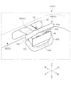
- FIG. 2 is a perspective view of the vehicle interior equipment, the operating unit, and the display unit inside the vehicle, showing the operating unit and the display unit in the "storage position.”
- FIG. 13 is a diagram showing the operation unit and the display unit in the "deployed position.”
- FIG. 13 is a diagram showing the operation unit and the display unit in the "storage position.”
- 13 is a diagram for explaining how the operation unit and the display unit are switched from the "storage position" to the "deployed position.”
- FIG. FIG. 13 is a diagram showing the operation unit and the display unit in the "deployed position.”
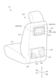
- FIG. 11 is a perspective view of a first vehicle seat, an operating unit, and a display unit of a vehicle according to a second embodiment, showing the operating unit and the display unit in a "storage position" state.
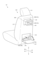
- FIG. 13 is a diagram showing the operation unit and the display unit in the "deployed position.” 1 is a side cross-sectional view of the first vehicle seat, showing the operation unit and the display unit in the "storage position.”
- FIG. FIG. 13 is a diagram showing the operation unit and the display unit in the "deployed position.”
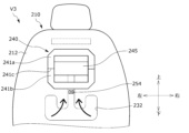
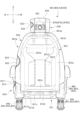
- FIG. 13 is a rear view of the first vehicle seat, the operating unit, and the display unit of the vehicle of the third embodiment, showing the operating unit and the display unit in the "storage position.”
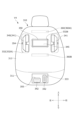
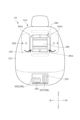
- FIG. 13 is a rear view of the first vehicle seat, the operating unit, and the display unit of the vehicle of the third embodiment, showing the operating unit and the display unit in the "storage position.”
- FIG. 13 is a diagram showing the operation unit and the display unit in the "deployed position.”
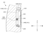
- FIG. 2 is a side cross-sectional view of the first vehicle seat, showing the steering unit and the display unit in the "storage position.”
- FIG. 13 is a diagram showing the steering unit and display unit in the "deployed position.”
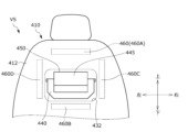
- FIG. 13 is a rear view of the first vehicle seat, the operating unit, and the display unit of the vehicle of the fourth embodiment, showing the operating unit and the display unit in the "storage position.”
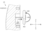
- FIG. 13 is a diagram showing the operation unit and the display unit in the "deployed position.”
- FIG. 13 is a diagram illustrating a state in which the operation unit and the display unit are in the "storage position.” 13 is a diagram illustrating the state of the operation unit and the display unit in the "deployed position.”
- FIG. 1 is a side view of the first vehicle seat, showing the operation unit (steering unit, acceleration/deceleration operation unit) and the foot support member in the "storage position.”
- FIG. 1 is a diagram showing the steering unit, acceleration/deceleration operation unit, and foot support member in the "deployed position” state.
- FIG. 13 is a rear view of the first vehicle seat, the operating unit, and the display unit of the vehicle of the fifth embodiment, showing the operating unit and the display unit in the "storage position.”
- FIG. 13 is a diagram showing the operation unit and the display unit in the "deployed position.”
- FIG. 2 is a side cross-sectional view of the first vehicle seat, showing the steering unit and the display unit in the "storage position.”
- FIG. 13 is a diagram showing the steering unit and display unit in the "deployed position.”
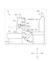
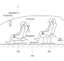
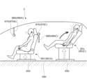
- 13 is a side view of a vehicle of a sixth embodiment, including a first vehicle seat, a second vehicle seat, an operating unit, and a display unit, the operating unit and the display unit being in the "deployed position.”
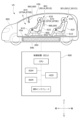
- FIG. FIG. 13 is a diagram illustrating the interior space of a vehicle according to a seventh embodiment.
- FIG. 23 is a top view of the vehicle of the eighth embodiment.
- FIG. 13 is an overall view of a vehicle seat system according to a ninth embodiment.
- FIG. 2 is a rear view of the vehicle seat showing the position of the imaging device.
- FIG. 11 is a rear view of the vehicle seat of the modified example, showing the position of the imaging device.
- 1 is a block diagram showing a hardware configuration and functions of a vehicle seat system.
- FIG. 2 is a side view of a vehicle seat, a display device, and an imaging device.
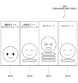
- FIG. 4 is a diagram showing an example of a display screen of a display device.
- FIG. 2 is a side view of a vehicle seat, a display device, and an imaging device.
- FIG. 4 is a diagram showing an example of a display screen of a display device.
- the first to eighth embodiments relate to a "vehicle” that enables more effective use of the interior space of the vehicle.
- the "front-rear direction of the vehicle” refers to the front-rear direction of the vehicle when it is normally running.
- the “inner side of the width of the vehicle” refers to the interior side of the vehicle (inside the vehicle) with respect to the vehicle door, and the “outer side of the width of the vehicle” refers to the exterior side of the vehicle (outside the vehicle) with respect to the vehicle door.
- the vehicle V1 is, for example, a vehicle (automobile) and is a vehicle (for example, an electric vehicle) equipped with two rows of vehicle seats 10, 20 in the front-to-rear direction of the vehicle V1.
- the vehicle V1 may be a vehicle equipped with three or four or more rows of vehicle seats.
- the vehicle V1 is a vehicle that can be driven by an occupant seated in the rear row of the vehicle seat 20.
- the driving operation unit 40 can be stored in the storage recess 32. This allows the occupant seated in the rear seat to effectively utilize the space inside the vehicle.
- the vehicle V1 is a vehicle that allows passengers seated in the rear row to drive the vehicle, and the rear seats serve as a cockpit (driver's seat, pilot's seat).
- the vehicle V1 comprises a vehicle body 1, a vehicle floor 2, a center console 3, a dashboard 4, a first vehicle seat 10, a second vehicle seat 20, a driver's operation console 30, a driver's operation unit 40, and a display unit 45.
- the vehicle V1 also includes switching members 50, 55 for switching between the driving operation unit 40 and the display unit 45, a plurality of airbag devices 60, and a driving control device .
- a driving control device 70 is attached inside the center console 3
- a front driving operation unit 5 is attached to the rear surface of the dashboard 4 .
- the vehicle body 1 corresponds to the vehicle body, and includes a side wall portion 1a that forms the side wall of the vehicle V1, a top wall portion 1b that forms the ceiling of the vehicle V1, a bottom wall portion 1c that forms the bottom wall of the vehicle V1, a front wall portion 1d, and a rear wall portion 1e.
- the vehicle floor 2 is a vehicle body floor for mounting a center console 3, a dashboard 4, vehicle seats 10, 20, a driver's control console 30, etc., and is disposed on the bottom wall portion 1c of the vehicle body 1.
- An area enclosed by the vehicle floor 2, the side wall 1a, the top wall 1b, the front wall 1d, and the rear wall 1e inside the vehicle V1 constitutes a cabin (internal space) of the vehicle V1. Occupants spend time inside the cabin while the vehicle V1 is traveling.
- a vehicle battery vehicle-mounted battery
- the vehicle battery is electrically connected to, for example, the drive device, various electric devices (electrical equipment devices), the control device, and the vehicle seats 10 and 20 of the vehicle V1, and supplies power to these devices.
- the first vehicle seat 10 is a seat that corresponds to a front seat, and is provided on the vehicle floor 2 and positioned slightly rearward of the dashboard 4 .
- An occupant seated in the first vehicle seat 10 can drive the vehicle V by operating a front driving operation unit 5 provided on the dashboard 4.
- the first vehicle seat 10 comprises a seat body having a seat cushion 11, a seat back 12 and a headrest 13, a rail device 15 for moving the seat body in the front-rear direction relative to the vehicle floor 2, a seat rotation device 16 for rotating the seat body around an axis along the up-down direction relative to the vehicle floor 2, a height link device 17 for raising and lowering the seat body relative to the vehicle floor 2, and a reclining device 18 for rotatably connecting the seat back 12 to the seat cushion 11.
- the seat cushion 11 is a seating portion that supports a seated person from below, and includes a cushion frame that serves as a skeleton, a padding material that is placed on the cushion frame, and a skin material that covers the cushion frame and the padding material.
- the seat back 12 is a backrest portion that supports a seated occupant from behind, and includes a back frame, a padding material, and a covering material.
- the headrest 13 supports the head of a seated occupant from behind.
- the occupant seated in the first vehicle seat 10 can turn around to face the occupant seated in the second vehicle seat 20 (rear seat) and come into contact with each other. In other words, the occupants can spend their time comfortably inside the cabin.
- the second vehicle seat 20 is a seat equivalent to a rear seat, and is provided on the vehicle floor 2 and positioned slightly rearward of the first vehicle seat 10 and the driver's operation console 30.
- An occupant seated in the second vehicle seat 20 can drive the vehicle V by operating a driving operation unit 40 provided on the driving operation console 30.
- the second vehicle seat 20 includes a seat body having a seat cushion 21, a seat back 22, and a headrest 23, a rail device 25, a seat rotation device 26, a height link device 27, and a reclining device 28.
- the driver's operation console 30 is disposed between the first vehicle seat 10 and the second vehicle seat 20 in the fore-and-aft direction, and is an interior component of a vehicle for mounting the driver's operation unit 40, the display unit 45, and the airbag device 60.
- the driver's console 30 is installed on the vehicle floor 2 and extends from the side wall portion 1 a of the vehicle body 1 toward the center of the center console 3 .
- the driving operation console 30 comprises an operation console main body 31, a storage recess 32 (storage section) formed in a concave shape on the rear surface of the operation console main body 31, and a storage recess 33 formed in a concave shape on the rear surface of the operation console main body 31 and positioned lower than the storage recess 32.
- airbag devices 60A (airbag 61A) and 60B (airbag 61A) are attached at different positions.
- the driving operation unit 40 is also referred to as a rear driving operation unit, as shown in FIGS. 1 to 4C, and is operated by an occupant seated in the second vehicle seat 20.
- the driving operation unit 40 includes a steering unit 41 (steering wheel) for steering the vehicle V1, and an acceleration/deceleration operation unit 42 (operation pedals) for controlling the acceleration and deceleration of the vehicle V1.
- the steering unit 41 is switchable between a "storage position” shown in FIG. 2 in which it is stored in the storage recess 32 of the driver's control console 30, and a “deployed position” shown in FIG. 3 in which it is deployed from the storage recess 32.
- the steering unit 41 is, for example, a foldable operating handle that is stored in the storage recess 32 in a folded state, and when unfolded from the storage recess 32, it expands vertically to form the shape of an operating handle that can be operated by the occupant.
- the steering section 41 has a first steering portion 41a and a second steering portion 41b that are divided into upper and lower portions, and a joint portion 41c that connects the first steering portion 41a and the second steering portion 41b.
- the acceleration/deceleration operation unit 42 is switchable between a “storage position” shown in FIG. 2 in which it is stored in the storage recess 33 of the driver's operation console 30, and a “deployed position” shown in FIG. 3 in which it is deployed from the storage recess 33.
- the acceleration/deceleration operation units 42 are, for example, an accelerator pedal and a brake pedal, and are arranged side by side on the left and right.
- the acceleration/deceleration operation unit 42 may be an organ pedal or a hanging pedal.
- the display unit 45 is a display that displays information related to the operation of the vehicle V, and is arranged near the steering unit 41 and stored in the storage recess 32 together with the steering unit 41.
- the display unit 45 displays information related to the operation of the vehicle V1, such as a speedometer, a tachometer, a fuel meter, etc., as well as the current position information of the vehicle V1, navigation information, etc.
- the steering unit 41 and the display unit 45 are switched by a switching member 50.
- the acceleration/deceleration operation unit 42 is switched by a second switching member 55.
- the switching member 50 is attached to the driver's operation console 30 (storage recess 32) and is a member for causing the steering unit 41 and the display unit 45 to protrude rearward from the storage recess 32.
- the switching member 50 allows the steering unit 41 and the display unit 45 to be pulled out (exposed) in front of the occupant seated in the second vehicle seat 20.
- the switching member 50 has a cylindrical first telescopic member 51 that is attached to the inside of the storage recess 32 and holds the steering section 41 in an extendable and contractible manner, and a second telescopic member 52 that is inserted into the first telescopic member 51 and holds the display section 45 in an extendable and contractible manner.
- the first telescopic member 51 has a structure that extends so as to cause the steering section 41 to protrude (project) rearward in the fore-and-aft direction of the vehicle V1.
- the second extendable member 52 has a structure that extends so as to cause the display unit 45 to protrude (project) rearward in the fore-and-aft direction of the vehicle V1.
- the extension/contraction members 51, 52 are connected to a drive unit (drive motor) not shown, and can perform extension/contraction operations by receiving a predetermined operation from the user and controlling the drive unit by the operation control device 70.
- the steering unit 41 may be biased in a deploying direction by a biasing spring (not shown). In this way, when the steering unit 41 is released from the state stored in the storage recess 32, it can be automatically deployed by being biased by the biasing spring, as shown in Figures 4A to 4C.
- the steering unit 41 and the display unit 45 are independently movable by the extendable members 51 and 52 and are stored in the storage recess 32 .
- the display unit 45 is disposed slightly rearward of the steering unit 41 and surrounded by the steering unit 41. This allows the occupant to operate the steering unit 41 while checking the display unit 45.
- a cutout portion 41d is formed at the rear end of each of the first steering portion 41a and the second steering portion 41b constituting the steering unit 41 to avoid interference with the display unit 45.
- the first telescopic member 51 is attached to the driver's operation console 30 so as to be rotatable about an axis along the extending direction of the first telescopic member 51. When the driver rotates the steering unit 41, the rotational motion can be transmitted to a gear box (steering gear box) (not shown).
- the second switching member 55 is attached to the driver's operation console 30 (the storage recess 33 ) and is a member for causing the acceleration/deceleration operation unit 42 to protrude rearward from the storage recess 33 .
- the second switching member 55 allows the acceleration/deceleration operation unit 42 to be pulled out (exposed) in front of the occupant seated in the second vehicle seat 20 .
- the second switching member 55 is attached to the inside of the storage recess 33 and has an extendable rod 56 that extends and retracts the acceleration/deceleration operation unit 42 .
- the telescopic rod 56 is connected to a drive unit (drive motor) not shown, and can perform telescopic motion by receiving a predetermined operation from the user and controlling the drive unit by the operation control device 70.
- a gear box not shown.
- the airbag device 60 includes airbag devices 60A and 60B each built into the driver's control console 30.
- the airbag device 60A is disposed on the driver's operation console 30 on the front side of the second vehicle seat 20, that is, on the front side of the occupant seated in the second vehicle seat 20.
- the airbag device 60A is disposed at a position slightly above the storage recess 32.
- the airbag device 60A is configured such that, when the vehicle V1 (drive control device 70) detects an external impact, the airbag 61A in a folded state inflates and deploys rearward. Therefore, a vehicle V1 can be realized that enables an occupant seated in the second vehicle seat 20 (rear seat) to perform driving operations and thereby improves safety technology during the driving operations.
- the airbag device 60B is disposed on the driver's operation console 30 on the side of the second vehicle seat 20, i.e., on the side (right side) of an occupant seated on the second vehicle seat 20. In other words, the airbag device 60B is disposed on the side wall portion 1a side of the vehicle V1.
- the airbag device 60B is configured so that when the vehicle V1 (driving control device 70) detects an external impact, the folded airbag 61B inflates and deploys from the outside to the inside in the width direction of the vehicle V1.
- the driving operation unit 40 and the airbag devices 60A, 60B are disposed at different positions on the driving operation console 30. Further, the airbag devices 60A, 60B are disposed at positions on the driver's operation console 30 that are different from the storage recess 32 . Therefore, the airbag devices 60A, 60B can be suitably disposed in the driver's operation console 30 so as not to interfere with other components.
- the driving control device 70 is an electronic control unit (ECU) that controls the driving of the vehicle V1, and performs overall electrical control within the vehicle V1.
- the driving control device 70 accepts a specified selection by the user and controls the front driving operation unit 5 and the driving operation unit 40 (rear driving operation unit) to switch between an "operable state” in which driving operation is possible, and an “inoperable state” in which driving operation is not possible.
- the driving control device 70 when the driving control device 70 receives a user's selection of the driving operation unit 40, the driving control device 70 places the front driving operation unit 5 in an "inoperable state” and controls the driving operation unit 40 to be switched to an "operable state”. Then, the driving control device 70 operates the switching members 50, 55 to switch the driving operation unit 40 and the display unit 45 from the "stored position (storage position)" to the "deployed position". In addition, by setting the driving operation unit 40 to the "operable state", the driving control device 70 causes the display unit 45 to display information regarding the driving of the vehicle V1.
- the driving control device 70 controls the front driving operation unit 5 to be in an "operable state” and switches the driving operation unit 40 to an "inoperable state”.
- the driving operation unit 40 and the display unit 45 are then held in the "stored position (stowed position)".
- the driving control device 70 when an external impact is detected by a detection sensor (not shown) and the driving control device 70 receives a detection signal from the detection sensor, it deploys the airbag of one of the multiple airbag devices 60A, 60B that corresponds to the switching position of the driving operation unit 40.
- the driving control device 70 may inflate and deploy the airbag devices 60A and 60B (or may deploy only the airbag device 60B).
- the driving control device 70 may inflate and deploy the airbag device 60B.
- the vehicle V1 may further include airbag devices other than the airbag devices 60A and 60B.
- the driving control device 70 may operate the switching members 50, 55 to switch the driving operation unit 40 from the “deployed position” to the “storage position (stored position)" when an external impact is detected by a detection sensor (not shown).
- vehicle V2 is equipped with a first vehicle seat 110, a second vehicle seat (not shown), a driving operation unit 140 (steering unit 141, acceleration/deceleration operation unit 142), a display unit 145, switching members 150, 155, a locking device 154, an airbag device 160, and a driving control device (not shown).
- the driving operation unit 140 is for a passenger seated in the second vehicle seat (rear seat) to drive and operate the vehicle, and corresponds to a rear driving operation unit.
- the first vehicle seat 110 corresponds to a front seat, and includes a seat cushion 111 , a seat back 112 , and a headrest 113 .
- the rear surface of the seat back 112 is formed with a recessed storage recess 132 and a recessed storage recess 133 disposed below the storage recess 132 .
- the steering unit 141 and the display unit 145 are stored in the storage recess 132.
- a cover 153 that covers the storage recess 132 is attached to an opening of the storage recess 132.
- the acceleration/deceleration operation unit 142 is stored in the storage recess 133.
- a plate-shaped foot support member 157 that covers the storage recess 133 is attached to an opening of the storage recess 133.
- An airbag device 160 (airbag 161 ) is attached inside the upper portion of the seat back 112 .
- the steering section 141 is switchable between a "storage position” in which it is stored in the storage recess 132 and a “deployed position” in which it is deployed from the storage recess 132.
- the steering unit 141 is, for example, a frame-shaped operating handle (operating steering wheel) and is deployed to a position protruding rearward from the storage recess 132.
- the acceleration/deceleration operation unit 142 can be switched between a "storage position” in which it is stored in the storage recess 133 and a “deployed position” in which it is deployed from the storage recess 133.
- the acceleration/deceleration operation unit 142 is, for example, an accelerator pedal and a brake pedal, and is arranged side by side on the left and right.
- the display unit 145 is a display, is disposed within the frame of the steering unit 141, and is stored in the storage recess 132 together with the steering unit 141.
- the steering unit 141 and the display unit 145 are switched by a switching member 150.
- the acceleration/deceleration operation unit 142 is switched by a second switching member 155.
- the switching member 150 has a link mechanism (multi-joint link mechanism) made up of a plurality of links 151 , and is attached to the storage recess 132 .
- the switching member 150 can move the steering unit 141 and the display unit 145 to the “storage position” by folding multiple links 151.
- the switching member 150 is fixed to the tip end (rear end) of the link 151 and has a plate-shaped holding member 152 that holds the steering unit 141 and the display unit 145.
- the holding member 152 is provided inside the steering section 141 and is connected to an inner surface in the width direction of the steering section 141.
- the holding member 152 is also connected to the rear surface of the display section 145.
- the link mechanism may be attached directly to the steering unit 141 or the display unit 145.
- the switching member 150 is connected to a drive unit (drive motor) not shown, and can perform an extension/contraction operation by receiving a predetermined operation from a user and controlling the drive unit by an operation control device.
- the switching member 150 is attached to the first vehicle seat 110 so as to be rotatable about an axis along the extension/retraction direction of the link mechanism. When the occupant rotates the steering unit 141, the rotational motion can be transmitted to a steering gear box (not shown).
- the cover 153 is, for example, a retractable shade (roll curtain) and is attached to the upper end of the opening of the storage recess 132 .
- the cover 153 can be switched between a "covered state” in which the cover 153 covers the storage recess 132 as shown in FIG. 7A and an "opened state” in which the cover 153 exposes the storage recess 132 as shown in FIG. 7B.
- an engaging member may be fixed to the tip of the cover 153, and an engaged member may be attached to the lower end of the opening of the storage recess 132. The engaging member and the engaged member are engaged with each other, whereby the cover 153 covers the storage recess 132.
- the locking device 154 is provided at the bottom of the storage recess 132 and is capable of holding the steering unit 141 stored in the storage recess 132 and locking the operation of the steering unit 141 .
- the locking device 154 may lock the steering section 141 by engaging with a notched portion (not shown) formed in the steering section 141 .
- the locking device 154 can be locked and unlocked under the control of an operation control device, or may be manually locked and unlocked.
- the second switching member 155 is attached to the inside of the storage recess 133, and has an extendable rod 156 that extends and retracts the acceleration/deceleration operation unit 142.
- the telescopic rod 156 is connected to a drive unit (drive motor) not shown, and can perform telescopic motion by receiving a predetermined operation from a user and controlling the drive unit by an operation control device.
- the foot support member 157 is rotatably attached to a lower portion of the first vehicle seat 110 (seat back 112) via a rotation shaft.
- the foot support member 157 can be switched between a "covered state” in which it covers the storage recess 133 and a “deployed state” in which it exposes the storage recess 133 and supports the feet of the occupant from below.
- the foot support members 157 extend rearwardly from the first vehicle seat 110 when in the "deployed" state shown in FIG.
- the airbag device 160 is provided at the upper end (upper portion) of the seat back 112, and is disposed in a position facing an occupant seated in the second vehicle seat (rear seat). Specifically, the airbag device 160 is disposed at a position slightly above the storage recess 132 . The airbag device 160 is configured so that, when the vehicle V2 detects an external impact, the airbag 161 in a folded state inflates and deploys rearward.
- the driving control device mounted inside the vehicle V2 When the driving control device mounted inside the vehicle V2 receives a selection of the driving operation unit 140 by the user, it operates the switching members 150, 155 to switch the driving operation unit 140 and the display unit 145 from the "storage position (stored position)" to the “deployed position.” It also causes the display unit 145 to display information related to the driving of the vehicle V2.
- the driving control device also controls the driving operation unit 140 to switch between an “operable state” and an “inoperable state”. When the driving operation unit 140 is in the “inoperable state”, the driving control device controls the locking device 154 to lock the driving operation unit 140 stored in the storage recess 132.
- a vehicle V3 of a third embodiment will be described with reference to FIGS. 8 to 10B. Note that explanations of the contents that overlap with those of the above-mentioned vehicles V1 and V2 will be omitted.
- vehicle V3 is equipped with a first vehicle seat 210, a second vehicle seat (not shown), a driving operation unit 240, a display unit 245, a switching member 250, a locking device 254, an airbag device 260, and a driving control device (not shown).
- the driving operation unit 240 is for a passenger seated in the second vehicle seat (rear seat) to drive and operate the vehicle, and corresponds to a rear driving operation unit.
- the first vehicle seat 210 is a seat equivalent to a front seat, and includes a seat back 212.
- a storage recess 232 having a recessed shape is formed on the rear surface of the seat back 212.
- the storage recess 232 stores the driving operation unit 240, the display unit 245, and the switching member 250.
- a cover 253 is attached to the opening of the storage recess 232.
- An airbag device 260 (airbag 261 ) is attached inside the upper portion of the seat back 212 .
- the driving operation unit 240 is switchable between a "storage position” in which it is stored in the storage recess 232 and a “deployed position” in which it is deployed from the storage recess 232.
- the driving operation unit 240 is a foldable operating handle, and in a folded state is stored in the storage recess 232. When unfolded from the storage recess 232, it unfolds vertically to become an operating handle that can be operated by the occupant.
- the driving operation unit 240 has a first steering portion 241a and a second steering portion 241b that are divided into upper and lower portions, and a joint portion 241c that connects the first steering portion 241a and the second steering portion 241b.
- the display unit 245 is a display that is disposed within the frame of the driving operation unit 240 and is stored in the storage recess 232 together with the driving operation unit 240.
- the driving operation unit 240 and the display unit 245 are switched by a switching member 250 .
- the switching member 250 has a link mechanism 251 (multi-joint link mechanism), and is attached to the storage recess 232 and stored in the storage recess 232.
- the switching member 250 can be rotated rearward so as to rise from the seat back 212, thereby moving the driving operation unit 240 and the display unit 245 to the "deployed position".
- the switching member 250 is fixed to the rear end of the link mechanism 251 and has a plate-shaped holding member 252 that holds the driving operation unit 240 and the display unit 245.
- the holding member 252 is provided within the frame of the driving operation unit 240, and is connected to an inner surface in the width direction of the driving operation unit 240.
- the holding member 252 is also connected to the rear surface of the display unit 245.
- the switching member 250 is attached to be rotatable around an axis along the front-rear direction with respect to the first vehicle seat 210. When the occupant rotates the driving operation unit 240, the rotational motion can be transmitted to a steering gear box (not shown).
- the cover 253 is, for example, a backboard, and is detachably attached to the seat back 212.
- the locking device 254 is provided at the bottom of the storage recess 232, and is capable of locking the driving operation unit 240 stored in the storage recess 232. Specifically, the locking device 254 engages with the switching member 250 (link mechanism 251) to lock the engagement.
- the airbag device 260 is provided at the upper end (upper portion) of the seat back 212, and is disposed in a position facing an occupant seated in the second vehicle seat (rear seat).
- the airbag device 260 is disposed at a position slightly above the storage recess 232 .
- a vehicle can be realized that can effectively utilize the interior space. Specifically, when a passenger sitting in the rear seat is not performing driving operations, the passenger can effectively utilize the space around the rear seat.
- a vehicle V4 of a fourth embodiment will be described with reference to FIGS. 11 to 14B.
- explanations of the contents that overlap with those of the above-mentioned vehicles V1 to V3 will be omitted.
- vehicle V4 is equipped with a first vehicle seat 310, a second vehicle seat 320, a driving operation unit 340 (steering unit 341, acceleration/deceleration operation unit 342), a display unit 345, switching members 350, 355, a locking device 354, a moving device 358, an airbag device 360, and a driving control device 370.
- the driving operation unit 340 is for an occupant seated in the second vehicle seat 320 (rear seat) to drive and operate the vehicle, and corresponds to a rear driving operation unit.
- the first vehicle seat 310 is a seat equivalent to a front seat, and includes a seat cushion 311 and a seat back 312.
- the rear surface of the seat back 312 is formed with recessed storage recesses 332A, 332B and a storage recess 333 having a recessed shape.
- the left and right storage recesses 332A store a steering unit 341.
- the storage recess 332B stores a display unit 345.
- the acceleration/deceleration operation unit 342 is stored in the storage recess 333.
- a plate-shaped foot support member 357 and a movement device 358 that supports the foot support member 357 are provided slightly below the storage recess 333.
- Airbag devices 360A, 360B are attached inside the upper and lower portions of the seat back 312.
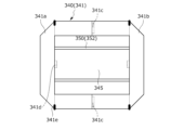
- the steering section 341 is switchable between a "storage position” in which it is stored in the storage recess 332A and a “deployed position” in which it is deployed from the storage recess 332A.
- the steering unit 341 is a foldable operating handle that is stored in the storage recess 332A in a folded state and is removable from the storage recess 332.
- the steering section 341 has a first steering portion 341a and a second steering portion 341b divided into left and right portions, a joint portion 341c connecting the first steering portion 341a and the second steering portion 341b, and a connection portion 341d for connecting to the switching member 350 (holding member 352).
- Each of the first steering portion 341a and the second steering portion 341b has a rotating portion 341e and is further capable of rotating between a folded state and an unfolded state.
- the steering section 341 is held by a locking device 354 provided at the bottom of the storage recess 332A.
- the locking device 354 clamps the divided steering portion 341a (341b) and locks the steering portion 341a.
- the acceleration/deceleration operation unit 342 can be switched between a "storage position" stored in the storage recess 333 and a “deployed position” deployed from the storage recess 333.
- the display unit 345 is a display that is disposed within the frame of the steering unit 341 and is stored in the storage recess 332B separately from the steering unit 341.
- the display unit 345 is held by a switching member 350 (holding member 352).
- the switching member 350 has an expandable member 351 that expands and contracts the display unit 345, and a plate-shaped holding member 352 that is fixed to the rear end of the expandable member 351 and holds the display unit 345.
- the holding member 352 is provided within the frame of the steering section 341, and is connected to an inner surface in the width direction of the steering section 341.
- the holding member 352 is also connected to the rear surface of the display section 345.
- the switching member 350 is attached to the first vehicle seat 310 so as to be rotatable about an axis along the front-rear direction. When the occupant rotates the steering unit 341, the rotational motion can be transmitted to a steering gear box (not shown).
- the second switching member 355 is attached to the inside of the storage recess 333, and has an extendable rod 356 that extends and retracts the acceleration/deceleration operation unit 342.
- the foot support member 357 is supported by a moving device 358 .
- the foot support member 357 can be switched between a "storage position” in which it is stored within the first vehicle seat 310 and a "support position” in which it protrudes rearward from the first vehicle seat 310 and supports the occupant's feet from below.
- the foot support members 357 extend from the first vehicle seat 310 towards the second vehicle seat 320 when in the "support position" shown in Figure 14B.
- the foot support member 357 has an engaging member 357 a that is engageable with an engaged portion 320 a provided on the second vehicle seat 320 .
- the foot support member 357 may be provided on the second vehicle seat 320 instead of the first vehicle seat 310. In that case, the foot support member 357 may extend from the second vehicle seat 320 toward the first vehicle seat 310. In other words, the foot support member 357 may be configured in the reversed front-to-back direction.
- the moving device 358 is, for example, a slide rail device, and includes a fixed rail 358a that extends along the front-rear direction of the first vehicle seat 310, and a slider 358b that is slidably attached to the fixed rail 358a and supports the foot support member 357.
- a vehicle can be realized that can effectively utilize the interior space. Specifically, when a passenger sitting in the rear seat is not performing driving operations, the passenger can effectively utilize the space around the rear seat.
- a vehicle V5 of a fifth embodiment will be described with reference to FIGS. 15 to 17B.
- explanations of the contents that overlap with those of the above-mentioned vehicles V1 to V4 will be omitted.
- vehicle V5 is equipped with a first vehicle seat 410, a second vehicle seat (not shown), a driving operation unit 440, a display unit 445, a switching member 450, an airbag device 460, and a driving control device (not shown).
- the driving operation unit 440 is for a passenger seated in the second vehicle seat (rear seat) to drive and operate the vehicle, and corresponds to a rear driving operation unit.
- the first vehicle seat 410 is a seat equivalent to a front seat, and includes a seat back 412.
- a storage recess 432 having a recessed shape is formed on the rear surface of the seat back 412.
- the storage recess 432 stores a driving operation unit 440 and a display unit 445 .
- Airbag devices 460 A, 460 B, 460 C, and 460 D are attached to the rear surface of the seat back 212 so as to surround the driving operation unit 440 and the display unit 445 .
- the driving operation unit 440 is switchable between a "storage position” in which it is stored in the storage recess 432 and a “deployed position” in which it is deployed from the storage recess 432.
- the driving operation unit 440 is a foldable operating handle, and in a folded state is stored in the storage recess 432. When unfolded from the storage recess 432, it unfolds vertically to become an operating handle that can be operated by the occupant.
- the driving operation unit 440 has a first steering portion 441a and a second steering portion 441b that are divided into upper and lower portions, and a joint portion 441c that connects the first steering portion 441a and the second steering portion 441b.
- the display unit 445 is a display that is disposed within the frame of the driving operation unit 440 and is stored in the storage recess 432 together with the driving operation unit 440 .
- the switching member 450 has an expandable member 451 that expands and contracts the driving operation unit 440 and the display unit 445, and a plate-shaped holding member 452 fixed to the rear end of the expandable member 451.
- the holding member 452 is provided within the frame of the driving operation unit 440, and is connected to an inner side surface in the width direction of the driving operation unit 440.
- the holding member 452 is also connected to the rear surface of the display unit 445.
- a vehicle can be realized that can effectively utilize the interior space. Specifically, when a passenger sitting in the rear seat is not performing driving operations, the passenger can effectively utilize the space around the rear seat.
- vehicle V6 is equipped with a first vehicle seat 510 (front seat), a second vehicle seat 520 (rear seat), a driving operation unit 540, a switching member 550, a rotating device 519 for rotating the armrest, an ottoman device 529, and a driving control device 570.
- the driving operation unit 540 is for an occupant seated in the second vehicle seat 520 to drive and operate the vehicle, and corresponds to a rear driving operation unit.
- the driving operation unit 540 has a steering unit 541 , an acceleration/deceleration operation unit 542 , and an operation acceptance unit 543 .
- the rotating device 519 and the ottoman device 529 correspond to a second switching member.
- the first vehicle seat 510 includes a seat cushion 511, a seat back 512, an armrest 514 attached to the seat back 512, and a rotation device 519 that rotatably connects the armrest 514 to the seat back 512.
- the armrest 514 can be switched by the rotation device 519 between a "standard position” for use by an occupant seated in the first vehicle seat 510 and an "extended position” in which the armrest 514 rotates rearward from the "standard position” for use by an occupant seated in the second vehicle seat 520.
- An operation acceptance unit 543 (operation button) for driving operations is provided on the bottom surface of the armrest 514. When the armrest 514 is in the "deployed position", the operation acceptance unit 543 is located on the top surface of the armrest 514 as shown in FIG.
- the second vehicle seat 520 comprises a seat cushion 521, a seat back 522, a movable member 529a attached to the tip of the seat cushion 521 and supporting the occupant's feet from below, and an ottoman device 529 that rotatably connects the movable member 529a to the seat cushion 521.
- the ottoman device 529 is a device that moves a movable member 529a back and forth between a "storage position” and an "expanded position" around a rotation shaft 529b at the tip of the seat cushion 521 as the center of rotation.
- the movable member 529a is stored on the seat cushion 521 side (the bottom surface of the seat cushion 521) when in the "storage position", and is protruded toward the front side of the seat when in the "deployed position".
- an acceleration/deceleration operation unit 542 and a foot support member 557 that supports the feet (heels) of the occupant are attached to the upper surface of the movable member 529a. Providing the foot support member 557 can prevent the occupant's feet from slipping.
- the switching member 550 is attached to the rear surface of the seat back 512 and causes the steering portion 541 to protrude rearward from the seat back 512.
- the switching member 550 allows the steering section 541 to be extended in front of an occupant seated in the second vehicle seat 520.
- the ottoman device 529 can be pulled out to the feet of the occupant by switching the movable member 529a, the acceleration/deceleration operation unit 542, and the foot support member 557 from the “storage position” to the “deployed position” shown in FIG.
- the rotation device 519 can switch the armrest 514 from the "standard position” to the "extended position” shown in FIG. 18, so that the armrest 514 can be pulled out to the passenger's hand.
- the driving control device 570 accepts a predetermined selection by the user and controls the rotation device 519, the ottoman device 529, and the switching member 550 to switch to the "deployed position" shown in FIG. 18. It also controls the steering unit 541, the acceleration/deceleration operation unit 542, and the operation acceptance unit 543 to switch from the "inoperable state” to the "operable state.”
- a vehicle can be realized that can effectively utilize the interior space. Specifically, when a passenger sitting in the rear seat is not performing driving operations, the passenger can effectively utilize the space around the rear seat.
- the vehicle V7 includes a vehicle body 601, a vehicle floor 602, a center console 603, a dashboard 604, a first vehicle seat 610 (front seat), a second vehicle seat (rear seat) (not shown), and a driving operation unit 640.
- the vehicle V7 also includes switching members 650 and 655, and a driving control device 670.
- a display unit 606 capable of displaying vehicle information and an imaging unit 607 capable of capturing images of the interior of the vehicle are attached to the connecting portion of the top wall portion 601b and the front wall portion 601d of the vehicle body 601.
- a storage section 603a and an in-vehicle information display section 603b are attached to the rear surface of the center console 603.
- Another in-vehicle information display section 603b is attached to the top surface of the center console 603.
- a driving control device 670 is attached inside the center console 603.
- a storage recess 604a is formed on the rear surface of the dashboard 604.
- the front driving operation unit 605 is stored in the storage recess 604a and can be protruded from the storage recess 604a.
- the first vehicle seat 610 includes a seat cushion 611 , a seat back 612 , a headrest 613 , and an armrest 614 .
- a storage recess 632 and a storage recess 633 disposed below the storage recess 632 are formed on the rear surface of the seat back 612 .
- a steering unit 641 is stored in the storage recess 632, and an acceleration/deceleration operation unit 642 is stored in the storage recess 633.
- an in-vehicle component operating unit 643 and a display unit 645 are attached to the rear surface of the seat back 612 .
- a cutout 613a is formed on the inner side of the headrest 613 in the width direction. Therefore, a passenger sitting in the rear seat can see the face of a passenger sitting in the front seat through the cutout 613a.
- a transparent member may be provided instead of the cutout 613a.
- the steering section 641 can be switched by a switching member 650 between a "storage position” and a “deployed position” in which it protrudes rearward from the storage position.
- the acceleration/deceleration operation unit 642 can be switched by a second switching member 655 between a "storage position” and a “deployed position” in which it protrudes rearward from the storage position.
- the driving control device 670 accepts a predetermined selection by the user and performs control so as to change the display contents of the in-vehicle information display unit 603b and the display unit 606.
- the driving control device 670 also controls the switching members 650, 655 to switch between the "storage position (stored position)" and the "deployed position”. It also controls the steering unit 641, the acceleration/deceleration operation unit 642, and the in-vehicle component operation unit 643 to switch from the "inoperable state" to the "operable state”.
- a vehicle can be realized that can effectively utilize the interior space. Specifically, when a passenger sitting in the rear seat is not performing driving operations, the passenger can effectively utilize the space around the rear seat.
- Vehicle V8 includes a vehicle body 701, a vehicle floor 702, a center console 703, a dashboard 704, a first vehicle seat 710, a second vehicle seat 720, a driver's control console 730, operation units 705, 740, and a display unit 745 (indoor equipment).
- the vehicle V1 also includes a switching member 750 for switching the operation unit 740, a driving control device 770, a projection device 780, and a goggle device 790 (wearable device).
- the display unit 745 is a large display screen (indoor equipment) that is disposed in the front part of the vehicle body 701 and can be pulled out from the ceiling wall of the vehicle body 701.
- the display unit 745 may be pulled out from the vehicle floor 702.
- An operation control device 770 is attached inside the center console 703 , and a projection device 780 (projector) is attached to the upper surface of the center console 703 .
- the projection device 780 is disposed behind the display unit 745 and is capable of projecting an image onto the display unit 745 .
- the goggle device 790 is, for example, virtual reality goggles (VR goggles), and is worn by a passenger (on the passenger's face) seated in the vehicle seats 710, 720.
- the operation units 705 and 740 are for operating the display contents projected on the display unit 745, and are operated by the occupant.
- the passenger can enjoy playing virtual reality games, for example, by operating the operation units 705, 740 (operation controllers) while wearing the goggle device 790 (VR goggles).
- a vehicle can be realized that can effectively utilize the interior space. Specifically, when a passenger sitting in the rear seat is not performing driving operations, the passenger can effectively utilize the space around the rear seat.
- the driving operation console 30, the first vehicle seat 10, and the second vehicle seat 20 are provided on the vehicle body 1.
- the first vehicle seat 10 is disposed in front of the driving operation console 30, and the second vehicle seat 20 is disposed in the rear of the driving operation console 30.
- a storage recess 32 (storage section) is formed in the driving operation console 30, and a driving operation section 40 for operating the vehicle V1 is stored in the storage recess 32.
- the driving operation unit 40 be configured so as to be switchable between the "storage position" and the "deployed position” by a switching member 50 provided on the driving operation console 30.
- the driving operation unit 40 (steering unit 41) has a shape of an operating handle, but this is not particularly limited.
- the shape of the driving operation unit 40 may be a cockpit type or a lever type.
- the driving operation unit 40, 140 is stored on the rear surface of the driving operation platform 30 or the first vehicle seat 110, but this is not particularly limited.
- the driving operation units 40, 140 may be detached and stored in an armrest or a center console.
- the driving operation units 40, 140 may be detached and installed in all the seats, and the occupants may be seated in the designated seats and drive the vehicle V1.
- a car was described as a specific example, but the invention is not limited to this and can be used for vehicles such as trains, buses, airplanes, ships, etc.
- the vehicle seat system S is a device that is mounted on a vehicle V9 and moves a part or the whole of a vehicle seat 801 (seat body 801a) in which a passenger sits, based on the passenger's facial expression.
- the system can arrange the seat configuration of the vehicle seat 801 so that the passenger can spend more comfortably inside the vehicle V9, for example, as shown in Figs. 25 to 28.
- the entertainment value inside the vehicle V9 can be increased.
- the vehicle seat system S recognizes the facial expression of an occupant seated in the vehicle seat 801. Then, based on the recognition information, it determines the type of facial expression of the occupant (e.g., a smile, etc.).
- the vehicle seat system S includes a plurality of vehicle seats 801 each arranged inside the vehicle V9, a plurality of imaging devices 870, a plurality of display devices 880, a plurality of audio acquisition devices 885, a plurality of vibration devices 890, a collision detection sensor 895, and a control device 900.
- the vehicle V9 is a vehicle (automobile).
- the vehicle seat 801 includes a front seat 801A (driver's seat), a front seat 801B (passenger's seat), a rear seat 801C, and a rear seat 801D.
- Each vehicle seat 801 comprises a seat body 801a having a seat cushion 810, a seat back 820 and a headrest 830, a slide rail device 840 that supports the seat body 801a so that it can move back and forth relative to the vehicle floor V9a, a height device 850 that connects the seat body 801a to the vehicle floor V9a so that it can be raised and lowered, and a reclining device 860 that connects the seat back 820 to the seat cushion 810 so that it can be rotated.
- the seat cushion 810, the seat back 820, and the headrest 830 correspond to a seat body 801a.
- the slide rail device 840, the height device 850, and the reclining device 860 correspond to a movable device.
- the cushion frame 811 comprises left and right side frames 811a arranged on the sides in the seat width direction, a plate-shaped pan frame 811b connecting the front portions of each side frame 811a, a pipe-shaped rear connecting frame 811c connecting the rear portions of each side frame 811a, and a number of elastic springs 811d that are hooked onto the pan frame 811b and the rear connecting frame 811c, respectively, and extend in a snake-like shape.
- the seat back 820 is a backrest portion that supports a seated occupant from behind, and includes a back frame 821 that serves as a skeleton, a padding material 822 , and a covering material 823 .
- the back frame 821 is made of a rectangular frame-like body that serves as the framework of the seat back 820 .
- the back frame 821 comprises a side frame 821a arranged laterally in the seat width direction, an inverted U-shaped upper frame 821b connecting the upper end portions of each side frame 821a, a plate-shaped lower frame 821c connecting the lower end portions of each side frame 821a, a plate-shaped connecting frame 821d connecting the upper portions of each side frame 821a, a plurality of wire members 821e hooked to the connecting frame 821d and the lower frame 821c, and a support plate 821f held by the plurality of wire members 821e and supporting an occupant.
- Left and right pillar guides 821g are fixed at a predetermined distance from each other in the widthwise central portion of the upper frame 821b.
- a reclining device 860 is attached to the connecting portion of the cushion frame 811 and the back frame 821
- a slide rail device 840 is attached to the lower portion of the cushion frame 811 via a height device 850 .
- the headrest 830 is a head portion that supports the head of an occupant from behind, and includes a pillar 831 that serves as a core material, a pad material 832 , and a cover material 833 .
- the pillar 831 is held by left and right pillar guides 821g.
- An imaging device 870 (imaging camera) is fixed to the rear surface of the headrest 830 (pillar 831).
- the slide rail device 840 is attached between the seat cushion 810 and the vehicle floor V9a in the vertical direction.
- the slide rail device 840 is fixed to the vehicle floor V9a and comprises left and right lower rails 841 extending in the fore-and-aft direction of the seat, left and right upper rails 842 supported slidably along the lower rails 841, a locking member 843 that locks the upper rails 842 against the lower rails 841 so that they cannot slide, and a rail operating lever (not shown) that releases the locked state of the locking member 843.
- a seat cushion 810 (cushion frame 811 ) is attached to the upper surfaces of the left and right upper rails 842 via a height device 850 .
- the height device 850 is attached between the slide rail device 840 and the seat cushion 810, as shown in FIGS.
- the height device 850 includes left and right first links 851 arranged on the front side of the seat, left and right second links 852 arranged on the rear side of the seat, a locking member 853 that locks the seat cushion 810 so that it cannot be raised or lowered, and a height operating lever (not shown) that releases the locked state of the locking member 853.
- the height device 850 can adjust the height of the seat cushion 810 by using the second link 852 as a driving link, for example.
- the reclining device 860 includes a reclining body 861 that is driven to rotate the seat back 820, a back rotation shaft 862, a spiral spring 863 that urges the seat back 820 to rotate forward around the back rotation shaft 862, and a reclining operation lever (not shown) that releases the locked state of the seat back 820.
- the reclining body 861 has a known locking mechanism, and the state of the seat back 820 can be switched between a "locked state” in which it is fixed to the seat cushion 810, and an “unlocked state” in which it can be rotated relative to the seat cushion 810.
- the back rotation shaft 862 is supported in the seat width direction on the seat cushion 810 side and the seat back 820 side.
- One end of the spiral spring 863 is anchored to the seat cushion 810 side, and the other end is anchored to the seat back 820 side.
- the imaging device 870 is a small camera (wide-angle camera) that captures an image of an occupant (the occupant's face) seated in the vehicle seat 801 .
- the imaging device 870 captures an image of the occupant, generates “imaging data”, and transmits the “imaging data” to the control device 900 .
- the imaging device 870 may be an imaging camera equipped with AI (artificial intelligence) and capable of analyzing captured images.
- the imaging device 870 may also be a 360-degree omnidirectional camera (a camera equipped with a fisheye lens), etc.
- the imaging devices 870 are disposed at positions corresponding to the front seat 801A, the front seat 801B, the rear seat 801C, and the rear seat 801D. Specifically, the imaging devices 870A and 870B are attached to the ceiling V9b and disposed in front of the front seats 801A and 801B, respectively. The imaging devices 870C and 870D are attached to the rear surfaces of the front seats 801A and 801B, respectively, and disposed in front of the rear seats 801C and 801D. More specifically, the imaging device 870C (870D) is attached to the rear surface of the headrest 830 of the front seat 801A (801B) via a cover member 834. It is possible to appropriately change the number and mounting positions of the image capturing devices 870. For example, as shown in FIG 23, a plurality of image capturing devices 870 may be mounted on one vehicle seat 801.
- FIG. 23 is a rear view of a modified vehicle seat 801.
- imaging devices 871 to 876 are attached to the rear surface of the vehicle seat 801.
- the imaging device 871 is attached to the upper end of the headrest 830 via a cover member 834 , and is disposed at a position higher than the imaging device 870 .
- the imaging device 872 is attached to the rear surface of the upper frame 821b, and is exposed rearward from the vehicle seat 801.
- the imaging devices 873 are attached to the left and right side portions of the upper frame 821b, and are exposed rearward from the vehicle seat 801.
- the imaging device 874 is attached to the center of the connecting frame 821d and is exposed rearward from the vehicle seat 801.
- the imaging device 870 can be arranged compactly within the vehicle V9.
- a vibration suppression device that suppresses vibration of the imaging device 870 may be provided in the portion of the vehicle seat 801 where the imaging device 870 is attached or in the surrounding area thereof. In this way, blurring of the image obtained by the imaging device 870 can be suppressed.
- the vibration suppression device may be, for example, a gimbal device or an elastic member.
- the elastic member may be, for example, a spring or a vibration-damping sponge (soft foam having low resilience). Alternatively, it may be a variable damping type damper that utilizes air pressure, hydraulic pressure, or an oil syringe (viscous material).
- the voice acquisition device 885 is a device that acquires the voice of an occupant seated in the vehicle seat 801, and is, for example, a microphone, a voice recorder, or the like.
- the voice acquisition device 885 acquires the voice of the occupant, generates “voice data”, and transmits the “voice data” to the control device 900 .
- the voice acquisition devices 885 are disposed at positions corresponding to the front seat 801A, the front seat 801B, the rear seat 801C, and the rear seat 801D.
- the voice acquisition device 885 may be mounted inside the display device 880. In other words, it may be configured as a part of the display device 880.
- the vehicle seat system S may further include a sound generating device (speaker) that generates a predetermined sound or music for an occupant seated in the vehicle seat 801 .
- the vehicle seat system S may further include an execution sensor (execution switch) for executing image capture by the image capture device 870.
- the execution sensor may be disposed on an interior member of the vehicle or on the outer surface of the vehicle seat. For example, an occupant can press and operate the execution sensor to capture an image by the image capture device 870.
- a control process using the captured image data described below may be performed to select the occupant with the most smile among the multiple occupants, and operate the vehicle seat 801 in which the occupant is seated.
- the smile of the occupant may be displayed on the display device 880.
- the control device 900 is a device that performs overall electrical control of the vehicle V9, and is, for example, an engine control unit (ECU).
- the control device 900 is connected to the slide rail device 840, the height device 850, the reclining device 860, the imaging device 870, the display device 880, the voice acquisition device 885, the vibration device 890 and the collision detection sensor 895 via an in-vehicle network.
- the control device 900 is a computer equipped with a CPU (processor) as a data calculation/control processing device, ROM and RAM as storage devices, a HDD, and a communication interface for sending and receiving information data via the in-vehicle network.
- the storage device of the control device 900 stores a vehicle seat program according to this embodiment in addition to a main program that performs the necessary functions of a computer.
- the functions of the vehicle seat system S are realized when this program is executed by the CPU (processor).
- the control device 900 mainly comprises a memory unit 910 for storing various programs and various data, a facial expression recognition unit 911, a facial expression judgment unit 912, a calculation unit 913, a movable amount determination unit 914, a movement control unit 915, an output unit 916, and a physical information detection unit 917.
- a CPU processor
- ROM read only memory
- RAM random access memory
- HDD hard disk drive
- communication interface various programs, and the like.
- the storage unit 910 stores "imaging data,”"audiodata,””occupant physique data,””movement amount data,” etc.
- Imaging data and "occupant physique data” are data obtained from the imaging device 870
- audio data is data obtained from the audio acquisition device 885, and are stored in a centralized manner.
- “Movement amount data” is data indicating the amount of movement of the movable devices 840, 850, 860, and is stored in a centralized manner.
- the control device 900 can move the movable devices 840, 850, 860 in response to the facial expression, voice, and physique of each occupant.
- the storage unit 910 also stores criteria data such as "facial expression criteria data” and "degree of change criteria data” which will be described later.
- the facial expression recognition unit 911 recognizes the facial expression of an occupant seated in the vehicle seat 801 . Specifically, the facial expression recognition unit 911 acquires "imaging data" captured by the imaging device 870, recognizes the facial expression of the occupant based on the "imaging data", and acquires "recognition information relating to facial expression”. More specifically, the facial expression recognition unit 911 detects position information of components of the face of the occupant and angle information indicating the tilt angle of the head based on the "imaging data”. Then, based on the position information and angle information, it obtains recognition information regarding the facial expression.
- the above recognition information includes, for example, information on the movements of lowering eyebrows, lifting outer eyebrows, lifting cheeks, lifting chin, making dimples, closing eyes, opening eyes, lifting inner eyebrows, lowering chin and opening lips, tensing eyelids, lifting corners of lips, pressing lips, pursing lips, pulling corners of lips sideways, sucking in lips, opening mouth, wrinkling nose, lifting upper lip, and blinking. It also includes information on up and down, left and right, and tilting movements of the head.
- the facial expression determination unit 912 determines the type of facial expression of the occupant (for example, whether the occupant is smiling) based on the recognition information by the facial expression recognition unit 911 . Specifically, the facial expression determination unit 912 determines the type of facial expression of the occupant and the degree of change in the facial expression (the magnitude of the facial expression) based on the above recognition information. For example, the facial expression determination unit 912 determines a "smile” as the predetermined facial expression of the occupant, and evaluates the "size of the smile" as the degree of change in the smile into multiple levels (multiple stages), and presents the evaluation level. A higher evaluation level indicates a greater change in facial expression. It is preferable that the storage unit 910 stores "facial expression reference data" for determining the type of facial expression of the occupant and "degree of change reference data" for determining the degree of change in a predetermined facial expression.
- the facial expression determination unit 912 may determine the type of facial expression of the occupant as a "smile", or may determine a surprised face, a happy face, a fearful face, a sad face, an angry face, a contemptuous face, or a blank face.
- the calculation section 913 calculates the number of times a predetermined facial expression has been determined by the facial expression determination section 912 . Specifically, the calculation unit 913 calculates the number of times a predetermined facial expression (for example, a smile) is determined by the facial expression determination unit 912 within a predetermined time period. The calculation unit 913 determines that a smile has occurred once when the smile exceeds a first reference time. In this case, the calculation unit 913 may determine that a smile has occurred twice when the smile continues to exceed a second reference time, and may determine that a smile has occurred three times when the smile continues to exceed a third reference time. The calculation unit 913 may calculate the time during which a smiling expression is made (the time during which it is made continuously) within a predetermined period of time.
- a predetermined facial expression for example, a smile
- the movement amount determination unit 914 determines the amount of movement of the vehicle seat 801 (seat body 801 a ) based on the number of times the predetermined facial expression (smile) is determined as calculated by the calculation unit 913 . Specifically, the movement amount determination unit 914 determines the movement amount of the movable device (the amount of rise of the height device 850) based on the number of times a smile is determined. The movement amount determination unit 914 may determine the movement amount of the height device 850 based on the number of times a smile is determined and the degree (magnitude) of change in the smile.
- the movement amount determination unit 914 may determine a larger movement amount (1.5 times or 2 times the movement amount) when the degree of the smile is large when the smile is determined (when the evaluation level is higher than normal). Alternatively, the movement amount determination unit 914 may determine a smaller movement amount (0.5 times the movement amount) when the degree of the smile is small when the smile is determined (when the evaluation level is lower than normal).
- the operation control unit 915 controls the operation of the movable device based on the determination information by the facial expression determination unit 912 . Specifically, the operation control unit 915 controls the operation of the movable devices 840, 850, 860 based on the movable amount of the seat body determined based on the determination information by the facial expression determination unit 912 and the information of the calculation result by the calculation unit 913. In other words, the operation control unit 915 moves a predetermined movable device based on the movable amount determined by the movable amount determination unit 914.
- the operation control unit 915 may control the seat body to return to the "reference position" after a predetermined time has elapsed after moving a part or the whole of the seat body from the "reference position (position where an occupant can sit)" to the "first movement position". In other words, the operation control unit 915 may move the seat body continuously from the "first movement position” to the "second movement position", or may move the seat body from the "reference position” to the "second movement position".
- the facial expression recognition unit 911 recognizes the facial expressions of a plurality of occupants. Then, the facial expression determination unit 912 determines the smile and the size of the smile for each occupant based on the above recognition information. Then, the operation control unit 915 raises the height device 850 so as to move the vehicle seat 801 in which a specific occupant is seated, based on the smile of each occupant and the size of the smile of each occupant.
- the height device 850 is not operating in the right front seat 801A, whereas the height device 850 is raising the seat body in the right rear seat 801C.
- a display screen shown in Fig. 26, which will be described later, is displayed on the display device 880.
- information related to the seat states of the vehicle seats 801A to 801D and information related to the facial expressions (smile, degree of smile, number of smiles) of the occupants corresponding to the vehicle seats 801A to 801D are displayed in conjunction with each other.
- the control device 900 controls the height device 850 to raise the seat body. This allows passengers to compete with each other, improving entertainment value.
- the control by the operation control unit 915 may be executed as shown in FIG. 27 and FIG.
- the facial expression recognition unit 911 recognizes the facial expressions of a plurality of occupants.
- the facial expression determination unit 912 determines the smile and the size of the smile for each occupant based on the above recognition information.
- the operation control unit 915 raises the height device 850 and the reclining device 860 so as to move the vehicle seat 801 in which a specific occupant is seated, based on the smile of each occupant and the size of the smile (number of times the occupant smiles).
- the height device 850 raises the seat body
- the height device 850 raises the seat body
- the reclining device 860 moves the seat body rearward.
- the display screen shown in Fig. 28 is displayed on the display device 880.
- information related to the seat states of the vehicle seats 801A to 801D and information related to the facial expressions (smile, size of smile, number of smiles) of the occupants corresponding to the vehicle seats 801A to 801D are displayed.
- the height device 850 and the reclining device 860 are controlled to move. This can improve entertainment value.
- the operation control unit 915 also acquires "occupant voice data" obtained by the voice acquisition device 885, and controls the operation of the vibration device 890 based on the volume of the occupant's voice. In this way, it can be recognized that the passenger is laughing out loud by the vibration operation of the vibration device 890. At this time, the vibration device 890 of the vehicle seat 801 in which the passenger is seated may be operated, or the vibration devices 890 of multiple vehicle seats 801 may be operated. In this way, it is possible to increase the entertainment value inside the vehicle.
- the operation control unit 915 may control the movable device (height device 850) to move the seat body based on the occupant's smile determined by the facial expression determination unit 912 and the volume of the occupant's voice obtained by the voice acquisition device 885. By doing so, it is possible to more accurately determine whether the occupant is laughing, and to operate the movable device based on the determination result. Specifically, the following applies: The movement amount determination unit 914 multiplies the movement amount of the movable device by a predetermined coefficient based on the voice data (volume of voice) obtained by the voice acquisition device 885.
- the movement amount determination unit 914 increases the movement amount when the voice of the occupant is louder than a predetermined voice reference value, and decreases the movement amount when the voice is quieter than the voice reference value.
- the movement amount determination unit 914 (which may be called the laughter determination unit) determines whether the occupant's voice is a "normal voice” or a "laughing voice", and if it determines that the voice is a "laughing voice", it multiplies the movement amount of the movable device (reference movement amount) by a predetermined coefficient (laughing voice coefficient).
- the movement amount determination unit 914 may make the determination based on the voice waveform data.
- the movement control unit 915 moves the movable devices 840 , 850 , and 860 based on the movement amount determined by the movement amount determination unit 914 .
- the operation control unit 915 controls the movable devices 840, 850, and 860 not to operate, regardless of the judgment information by the facial expression judgment unit 912 (the amount of movement determined by the amount of movement determination unit 914). In this way, operation of movable devices 840, 850, 860 can be stopped if a collision of vehicle V9 is predicted or if vehicle V9 has collided.
- the output unit 916 outputs first display information in which the facial expression of the occupant determined by the facial expression determination unit 912 is converted into a character's facial expression, and second display information based on the operation information of the movable device controlled by the operation control unit 915.
- the first display information is, for example, as shown in Fig. 26 and Fig. 28.
- the facial expression of each passenger is converted into the facial expression of a character (face mark) and is displayed. Specifically, it can be seen that the passenger sitting in the right rear seat 801C is smiling.
- the second display information is as shown in FIG. 26 (FIG. 28), for example. The number of times that each occupant has been determined to have a smile is counted and displayed.
- the number of times that the occupant seated in the right rear seat 801C has been determined to have a smile is three (four). Since the amount of movement of the movable device is determined based on the number of times that a smile has been determined, this is equivalent to information based on the operation of the movable device being displayed. In other words, it can be seen that the right rear seat 801C has a larger amount of movement than the right front seat 801A and the left front seat 801B.
- the output unit 916 outputs display information in which the character's facial expression is changed based on the change in the passenger's facial expression determined by the facial expression determination unit 912 .
- the character may be a facial mark, an avatar that pays homage to the face of a passenger, or an animal.
- the number of times a smile has been determined may be displayed by the number of cushions, or by the character's movements (the character gradually standing up).
- the physique information detection unit 917 detects physique information of the occupant seated in the vehicle seat 801 .
- the physique information detection unit 917 measures the length of the upper body, the length of the thighs, and the length of the lower legs as physique information of the occupant based on the image data of the occupant, and then detects mainly the position of the head of the occupant.
- the operation control unit 915 controls the operation of the movable devices 840, 850, 860 based on the physique information of the occupant obtained by the physique information detection unit 917, and moves the seat body so that the seat position corresponds to the imaging range of the imaging device 870. This makes it easier for the imaging device 870 to recognize the facial expression (smile) of the occupant.
- the operation control unit 915 controls the height device 850 so as to limit the lifting and lowering operation of the seat body based on the physique information of the occupant. In this way, the operation of the height device 850 can be limited based on the physique information of the occupant, allowing the occupant to sit comfortably.
- the operation control unit 915 limits the rise of the height device 850 so that the top of the occupant's head falls within the imaging range.
- the operation control unit 915 operates the reclining device 860 so that the occupant's facial expression is easily detected by the imaging device 870 (front position).
- the operation control unit 915 limits the ascent of the height device 850 based on the occupant's physique so that the head does not come into contact with the ceiling V9b of the vehicle V9.
- the operation control unit 915 controls the height device 850 so that the occupant's head falls within the imaging range, and adjusts the height of the seat body.
- the operation control unit 915 may control the height device 850 of the vehicle seat 801C on which the occupant sits in response to the movement, and further adjust the height of the seat body.
- the slide rail device 840 and the reclining device 860 may also be operated together. This makes it easier to recognize the facial expression (smile) of the occupant.
- the program of this embodiment is a program for realizing the above-mentioned facial expression recognition unit 911, facial expression determination unit 912, calculation unit 913, movable amount determination unit 914, motion control unit 915, output unit 916, and physique information detection unit 917 as functional components of a control device 900 having a storage unit 910.
- the CPU (processor) of the control device 900 executes this vehicle seat program.
- the program is executed, for example, when triggered by the acceptance of an instruction to start the system S through an operation by an occupant (user).
- step 1 the facial expression recognition unit 911 recognizes the facial expression of an occupant seated in the vehicle seat 801. Specifically, the facial expression recognition unit 911 acquires "imaging data” captured by the imaging device 870, recognizes the facial expression of the occupant based on the "imaging data”, and acquires "recognition information relating to facial expression”.
- the facial expression determination unit 912 determines the type of facial expression of the occupant (for example, whether the occupant is smiling) based on the recognition information by the facial expression recognition unit 911. Specifically, the facial expression determination unit 912 determines the type of facial expression of the occupant and the magnitude of the facial expression based on the above recognition information.
- step 3 the calculation unit 913 calculates the number of times a smile has been determined by the facial expression determination unit 912 . Specifically, the calculation unit 913 calculates the number of times a smile has been determined by the facial expression determination unit 912 within a predetermined period of time.
- the movement amount determination unit 914 determines the movement amount of the vehicle seat 801 based on the number of times a smile has been determined as calculated by the calculation unit 913 . Specifically, the movement amount determination unit 914 determines the movement amount of the movable device based on the number of times a smile is determined. As described above, the movement amount determination unit 914 may determine the movement amount of the movable device based on the number of times a smile has been determined and the size of the smile.
- the output unit 916 outputs first display information in which the facial expression of the occupant determined by the facial expression determination unit 912 is converted into a facial expression of the character, and second display information based on the operation information of the movable device controlled by the operation control unit 915.
- the second display information can also be said to be information based on the number of times a smile has been determined and the size of the smile. Specifically, the display screen is as shown in FIG.
- step 7 the control device 900 determines whether or not a request to stop the vehicle seat system S has been received through an operation by the occupant. If a request to stop the system S has been received (step 7: Yes), the process in FIG. 30 ends. On the other hand, if a request to stop the system S has not been received (step 7: No), the process returns to step 1 and the above process is repeated.
- the vehicle seat system and vehicle seat program described above make it possible to control the operation of a movable device based on the occupant's biometric information (e.g., the occupant's facial expression). It also makes it possible for the occupant seated in the vehicle seat to feel comfortable inside the vehicle.
- biometric information e.g., the occupant's facial expression
- the vehicle seat system S may, as a simple control, recognize the facial expression of an occupant seated in the vehicle seat 801, and when a predetermined facial expression of the occupant (the occupant's smile) is determined, control the operation of a predetermined movable device (height device 850).
- the vehicle seat system S may recognize the facial expression of an occupant seated in the vehicle seat 801 to determine whether the occupant is smiling, and may control the height device 850 to operate when the occupant's voice is recognized.
- the vehicle seat system S may be configured to include a vehicle seat 801, an imaging device 870, a voice acquisition device 885, a lighting device that adjusts the brightness inside the vehicle, and a control device 900 that controls these devices.
- the control device 900 may change the illumination color of the lighting device and perform imaging by the imaging device 870 according to the volume of the passenger's voice acquired by the voice acquisition device 885. This allows passengers to be photographed with natural expressions and also reduces energy consumption due to lighting.
- the system S may determine the passenger who is the loudest among the passengers, adjust the lighting at the seat where the passenger is seated, and capture the image. This allows the lighting to highlight the passenger who talks a lot, and allows the passenger's natural facial expression to be captured.
- the system S may further include a voice recording device (voice recording function) for recording the voices of the passengers.
- voice recording function voice recording function
- the system S may control the operation of the imaging device 870 attached to the rear surface of the seat back 820 based on the posture of the seat body (seat back 820). By doing so, the angle of view of the imaging device 870 (imaging camera) can be appropriately maintained in accordance with the posture of the seat body.
- the imaging device 870 is disposed at a position on the rear surface that does not overlap with the driving operation part. In this way, it is possible to capture images without interfering with the driving operation part.
- a vehicle seat system for use in an automobile has been described as a specific example, but the vehicle seat system is not limited to this and can be used in vehicles such as trains, buses, airplanes, ships, etc.
- the vehicle seat system includes a vehicle seat having a seat body on which an occupant can sit and a movable device that moves part or all of the seat body, and a control device that controls the operation of the movable device, and the control device preferably has an expression recognition unit that recognizes the expression of an occupant seated in the vehicle seat, an expression determination unit that determines the type of expression of the occupant based on recognition information by the expression recognition unit, and an operation control unit that controls the operation of the movable device based on determination information by the expression determination unit.
- the control device of this system recognizes the facial expression of the occupant, determines the type of facial expression of the occupant based on the recognition information, and controls the operation of the movable device based on the determination information.
- the operation of the seat movable device can be controlled according to the type of facial expression (change in facial expression) of the occupant. Therefore, the seat configuration of the vehicle seat can be arranged so that the occupant can spend more comfortably inside the vehicle. It can also improve entertainment value.
- the facial expression recognition unit recognizes the facial expressions of multiple occupants
- the facial expression determination unit determines the degree of change in facial expression for each occupant based on the recognition information for each occupant
- the operation control unit controls the movable device to move the seat body in which a specified occupant is seated based on the type of facial expression for each occupant and the degree of change in facial expression determined by the facial expression determination unit.
- the vehicle seat is provided with an imaging device that images an occupant seated in the vehicle seat
- the control device has a physique information detection unit that detects physique information of the occupant
- the operation control unit controls the operation of the movable device based on the physique information of the occupant from the physique information detection unit, and moves the seat body so that the seating position corresponds to the imaging range of the imaging device.
- the vehicle is provided with a display device used by an occupant seated in a vehicle seat
- the control device has an output unit that outputs first display information in which the occupant's facial expression determined by the facial expression determination unit is converted into a character's facial expression, and second display information based on operation information of the movable device controlled by the operation control unit, and the display device displays the first display information and the second display information output by the output unit toward the occupant.
- a predetermined facial expression e.g., a smile
- the amount of movement of the movable device can be displayed.
- the control device is provided with a display device used by an occupant seated in the vehicle seat, and has a calculation unit that calculates the number of times a predetermined facial expression has been determined by the facial expression determination unit, and an output unit that outputs display information based on the number of times the predetermined facial expression has been determined by the calculation unit, and the display device displays the display information output by the output unit toward the occupant.
- a predetermined facial expression e.g., a smile
- This improves entertainment value. For example, a smile can be quantified, which improves entertainment value.
- the control device has a calculation unit that calculates the number of times a specified facial expression is determined by the facial expression determination unit, and a movement amount determination unit that determines the amount of movement of the seat body based on the number of times the specified facial expression is determined by the calculation unit, and the operation control unit controls the movable device based on the amount of movement of the seat body determined by the movement amount determination unit, and moves the seat body.
- the movable device can be moved based on the number of times the occupant makes a specified facial expression (e.g., smiling), and other occupants can tell that the occupant is smiling from the amount of movement of the movable device.
- a voice acquisition device for acquiring the voice of an occupant seated in the vehicle seat, and the operation control unit controls the movable device to move the seat body based on the smiling facial expression of the occupant determined by the facial expression determination unit and the degree of the occupant's voice acquired by the voice acquisition device.
- a voice acquisition device is provided for acquiring the voice of an occupant seated in the vehicle seat
- a vibration device is provided for imparting vibrations to the occupant seated in the vehicle seat
- the operation control unit controls the operation of the vibration device based on the level of the occupant's voice acquired by the voice acquisition device.
- a collision detection unit that detects a vehicle collision, and when the collision detection unit detects a vehicle collision, the operation control unit controls the movable device not to operate regardless of the determination information by the facial expression determination unit.
- the movable device is a height device that connects the seat body to the vehicle floor so that it can be raised and lowered
- the control device has a physique information detection unit that detects physique information of an occupant seated in the vehicle seat
- the operation control unit controls the height device to restrict the raising and lowering movement of the seat body based on the occupant's physique information.
- the vehicle and the vehicle seat system according to the present invention have been mainly described.
- the above embodiment is merely an example for facilitating understanding of the present invention, and is not intended to limit the present invention.
- the present invention can be modified or improved without departing from the spirit of the present invention, and the present invention naturally includes equivalents thereof.
- Vehicle Vehicle body (car body) 1a Side wall portion 1b Top wall portion 1c Bottom wall portion 1d Front wall portion 1e Rear wall portion 2 Vehicle floor (vehicle floor) 3 Center console 4 Dashboard 5 Front driving operation section (front operation section) 10 First vehicle seat (first vehicle seat) 11 seat cushion 12 seat back 13 headrest 15 rail device 16 seat rotation device 17 height link device 18 reclining device 20 second vehicle seat (second vehicle seat) 21 seat cushion 22 seat back 23 headrest 25 rail device 26 seat rotation device 27 height link device 28 reclining device 30 driver's console (vehicle interior equipment) 31 Operation table body 32 Storage recess (storage section) 33 Storage recess (storage section) 40 Driving operation unit (operation unit, rear driving operation unit) 41 Steering section (operating handle) 41a: First steering portion; 41b: Second steering portion; 41c: Joint portion; 41d: Cutout portion; 42: Acceleration/deceleration operation portion (operation pedal); 45 Display unit 50 Switching member 51 First telescopic
Landscapes
- Engineering & Computer Science (AREA)
- Health & Medical Sciences (AREA)
- Mechanical Engineering (AREA)
- Life Sciences & Earth Sciences (AREA)
- Transportation (AREA)
- Aviation & Aerospace Engineering (AREA)
- General Health & Medical Sciences (AREA)
- Public Health (AREA)
- Veterinary Medicine (AREA)
- Animal Behavior & Ethology (AREA)
- Surgery (AREA)
- Molecular Biology (AREA)
- Medical Informatics (AREA)
- Heart & Thoracic Surgery (AREA)
- Physics & Mathematics (AREA)
- Biomedical Technology (AREA)
- Biophysics (AREA)
- Pathology (AREA)
- Dentistry (AREA)
- Oral & Maxillofacial Surgery (AREA)
- Chemical & Material Sciences (AREA)
- Psychiatry (AREA)
- Hospice & Palliative Care (AREA)
- Educational Technology (AREA)
- Combustion & Propulsion (AREA)
- Child & Adolescent Psychology (AREA)
- Developmental Disabilities (AREA)
- Physiology (AREA)
- Psychology (AREA)
- Social Psychology (AREA)
- Seats For Vehicles (AREA)
- Fittings On The Vehicle Exterior For Carrying Loads, And Devices For Holding Or Mounting Articles (AREA)
Abstract
L'invention concerne un véhicule en mesure d'utiliser plus efficacement l'espace interne du véhicule. Un véhicule (V1) comprend : un premier siège de véhicule (10) qui est disposé à l'intérieur du véhicule ; un deuxième siège de véhicule (20) qui est disposé à l'intérieur du véhicule et disposé dans une position derrière le premier siège de véhicule (10) ; et une unité d'opération de conduite (40) qui est montée sur une table d'opération de conduite (30) (composant intérieur de véhicule) située entre le premier siège de véhicule (10) et le deuxième siège de véhicule (20) et qui opère la conduite du véhicule. L'unité d'opération de conduite (40) est montée de manière à pouvoir être stockée dans un évidement de stockage (32) disposé dans la table d'opération de conduite (30).
Priority Applications (1)
| Application Number | Priority Date | Filing Date | Title |
|---|---|---|---|
| CN202480039617.6A CN121358634A (zh) | 2023-06-16 | 2024-06-11 | 交通工具 |
Applications Claiming Priority (8)
| Application Number | Priority Date | Filing Date | Title |
|---|---|---|---|
| US202363508623P | 2023-06-16 | 2023-06-16 | |
| US63/508,623 | 2023-06-16 | ||
| US202363586240P | 2023-09-28 | 2023-09-28 | |
| US63/586,240 | 2023-09-28 | ||
| JP2023-179710 | 2023-10-18 | ||
| JP2023179710A JP2024180237A (ja) | 2023-06-16 | 2023-10-18 | 乗り物 |
| JP2024004161A JP2025058823A (ja) | 2023-09-28 | 2024-01-15 | 乗り物用シートシステム |
| JP2024-004161 | 2024-01-15 |
Publications (1)
| Publication Number | Publication Date |
|---|---|
| WO2024257773A1 true WO2024257773A1 (fr) | 2024-12-19 |
Family
ID=93851966
Family Applications (1)
| Application Number | Title | Priority Date | Filing Date |
|---|---|---|---|
| PCT/JP2024/021246 Ceased WO2024257773A1 (fr) | 2023-06-16 | 2024-06-11 | Véhicule |
Country Status (2)
| Country | Link |
|---|---|
| CN (1) | CN121358634A (fr) |
| WO (1) | WO2024257773A1 (fr) |
Cited By (1)
| Publication number | Priority date | Publication date | Assignee | Title |
|---|---|---|---|---|
| US12503152B2 (en) * | 2023-09-20 | 2025-12-23 | Autox, Inc. | Device for concealing steering wheel and vehicle |
Citations (6)
| Publication number | Priority date | Publication date | Assignee | Title |
|---|---|---|---|---|
| JPH0277160U (fr) * | 1988-12-05 | 1990-06-13 | ||
| JPH07156807A (ja) * | 1993-07-15 | 1995-06-20 | Rolf Schmidt-Lutz | 自動車 |
| JP2014189126A (ja) * | 2013-03-27 | 2014-10-06 | Panasonic Corp | 車載機器と、それを搭載した自動車 |
| US20150131226A1 (en) * | 2006-01-04 | 2015-05-14 | Voxx International Corporation | Vehicle entertainment tablet unit and cradle |
| US20160375926A1 (en) * | 2015-06-29 | 2016-12-29 | Steering Solutions Ip Holding Corporation | Steering arrangement |
| US20210323594A1 (en) * | 2020-04-17 | 2021-10-21 | ZF Passive Safety Systems US Inc. | Steering wheel assembly |
-
2024
- 2024-06-11 WO PCT/JP2024/021246 patent/WO2024257773A1/fr not_active Ceased
- 2024-06-11 CN CN202480039617.6A patent/CN121358634A/zh active Pending
Patent Citations (6)
| Publication number | Priority date | Publication date | Assignee | Title |
|---|---|---|---|---|
| JPH0277160U (fr) * | 1988-12-05 | 1990-06-13 | ||
| JPH07156807A (ja) * | 1993-07-15 | 1995-06-20 | Rolf Schmidt-Lutz | 自動車 |
| US20150131226A1 (en) * | 2006-01-04 | 2015-05-14 | Voxx International Corporation | Vehicle entertainment tablet unit and cradle |
| JP2014189126A (ja) * | 2013-03-27 | 2014-10-06 | Panasonic Corp | 車載機器と、それを搭載した自動車 |
| US20160375926A1 (en) * | 2015-06-29 | 2016-12-29 | Steering Solutions Ip Holding Corporation | Steering arrangement |
| US20210323594A1 (en) * | 2020-04-17 | 2021-10-21 | ZF Passive Safety Systems US Inc. | Steering wheel assembly |
Cited By (1)
| Publication number | Priority date | Publication date | Assignee | Title |
|---|---|---|---|---|
| US12503152B2 (en) * | 2023-09-20 | 2025-12-23 | Autox, Inc. | Device for concealing steering wheel and vehicle |
Also Published As
| Publication number | Publication date |
|---|---|
| CN121358634A (zh) | 2026-01-16 |
Similar Documents
| Publication | Publication Date | Title |
|---|---|---|
| US11807183B2 (en) | Occupant protection apparatus | |
| JP7323754B2 (ja) | シートユニット | |
| JP2022030769A (ja) | シートリクライニング位置制御装置 | |
| JP7662960B2 (ja) | 表示システム | |
| KR102375150B1 (ko) | 수납식 차량 시트 | |
| WO2024257773A1 (fr) | Véhicule | |
| WO2023219144A1 (fr) | Système acoustique et véhicule | |
| JP2023179360A (ja) | 電気自動車及び車両用シート | |
| JP2022186661A (ja) | 表示システム及び車両 | |
| CN115339396B (zh) | 用于车辆的车载显示系统和车辆 | |
| JP5577605B2 (ja) | 車載ロボット装置 | |
| JP3783409B2 (ja) | 車両用乗員保護装置 | |
| CN118514615B (zh) | 车载影院系统及其控制方法、车机、车辆及存储介质 | |
| JP2025058823A (ja) | 乗り物用シートシステム | |
| CN114537142B (zh) | 副仪表板装置和车辆 | |
| CN121152736A (zh) | 座椅及座椅系统 | |
| JP2023110855A (ja) | 乗り物 | |
| WO2023085425A1 (fr) | Siège | |
| WO2026028513A1 (fr) | Siège de véhicule | |
| US20240431045A1 (en) | Movable display system and method for controlling the same | |
| KR200238671Y1 (ko) | 자동차용 다리 받침대 | |
| KR20210049242A (ko) | 폴더블 암레스트 | |
| CN114604094B (zh) | 车辆 | |
| JP2006131184A (ja) | 運転姿勢保持装置 | |
| CN121399679A (zh) | 车辆系统 |
Legal Events
| Date | Code | Title | Description |
|---|---|---|---|
| 121 | Ep: the epo has been informed by wipo that ep was designated in this application |
Ref document number: 24823388 Country of ref document: EP Kind code of ref document: A1 |
|
| NENP | Non-entry into the national phase |
Ref country code: DE |