WO2024257827A1 - 摩擦伝動ベルト - Google Patents
摩擦伝動ベルト Download PDFInfo
- Publication number
- WO2024257827A1 WO2024257827A1 PCT/JP2024/021499 JP2024021499W WO2024257827A1 WO 2024257827 A1 WO2024257827 A1 WO 2024257827A1 JP 2024021499 W JP2024021499 W JP 2024021499W WO 2024257827 A1 WO2024257827 A1 WO 2024257827A1
- Authority
- WO
- WIPO (PCT)
- Prior art keywords
- rubber
- layer
- rubber composition
- pulley
- fiber
- Prior art date
- Legal status (The legal status is an assumption and is not a legal conclusion. Google has not performed a legal analysis and makes no representation as to the accuracy of the status listed.)
- Ceased
Links
Images




Classifications
-
- C—CHEMISTRY; METALLURGY
- C08—ORGANIC MACROMOLECULAR COMPOUNDS; THEIR PREPARATION OR CHEMICAL WORKING-UP; COMPOSITIONS BASED THEREON
- C08L—COMPOSITIONS OF MACROMOLECULAR COMPOUNDS
- C08L21/00—Compositions of unspecified rubbers
-
- C—CHEMISTRY; METALLURGY
- C08—ORGANIC MACROMOLECULAR COMPOUNDS; THEIR PREPARATION OR CHEMICAL WORKING-UP; COMPOSITIONS BASED THEREON
- C08L—COMPOSITIONS OF MACROMOLECULAR COMPOUNDS
- C08L23/00—Compositions of homopolymers or copolymers of unsaturated aliphatic hydrocarbons having only one carbon-to-carbon double bond; Compositions of derivatives of such polymers
- C08L23/02—Compositions of homopolymers or copolymers of unsaturated aliphatic hydrocarbons having only one carbon-to-carbon double bond; Compositions of derivatives of such polymers not modified by chemical after-treatment
- C08L23/04—Homopolymers or copolymers of ethene
-
- F—MECHANICAL ENGINEERING; LIGHTING; HEATING; WEAPONS; BLASTING
- F16—ENGINEERING ELEMENTS AND UNITS; GENERAL MEASURES FOR PRODUCING AND MAINTAINING EFFECTIVE FUNCTIONING OF MACHINES OR INSTALLATIONS; THERMAL INSULATION IN GENERAL
- F16G—BELTS, CABLES, OR ROPES, PREDOMINANTLY USED FOR DRIVING PURPOSES; CHAINS; FITTINGS PREDOMINANTLY USED THEREFOR
- F16G1/00—Driving-belts
- F16G1/06—Driving-belts made of rubber
- F16G1/08—Driving-belts made of rubber with reinforcement bonded by the rubber
- F16G1/10—Driving-belts made of rubber with reinforcement bonded by the rubber with textile reinforcement
-
- F—MECHANICAL ENGINEERING; LIGHTING; HEATING; WEAPONS; BLASTING
- F16—ENGINEERING ELEMENTS AND UNITS; GENERAL MEASURES FOR PRODUCING AND MAINTAINING EFFECTIVE FUNCTIONING OF MACHINES OR INSTALLATIONS; THERMAL INSULATION IN GENERAL
- F16G—BELTS, CABLES, OR ROPES, PREDOMINANTLY USED FOR DRIVING PURPOSES; CHAINS; FITTINGS PREDOMINANTLY USED THEREFOR
- F16G5/00—V-belts, i.e. belts of tapered cross-section
- F16G5/04—V-belts, i.e. belts of tapered cross-section made of rubber
- F16G5/06—V-belts, i.e. belts of tapered cross-section made of rubber with reinforcement bonded by the rubber
- F16G5/08—V-belts, i.e. belts of tapered cross-section made of rubber with reinforcement bonded by the rubber with textile reinforcement
-
- F—MECHANICAL ENGINEERING; LIGHTING; HEATING; WEAPONS; BLASTING
- F16—ENGINEERING ELEMENTS AND UNITS; GENERAL MEASURES FOR PRODUCING AND MAINTAINING EFFECTIVE FUNCTIONING OF MACHINES OR INSTALLATIONS; THERMAL INSULATION IN GENERAL
- F16G—BELTS, CABLES, OR ROPES, PREDOMINANTLY USED FOR DRIVING PURPOSES; CHAINS; FITTINGS PREDOMINANTLY USED THEREFOR
- F16G5/00—V-belts, i.e. belts of tapered cross-section
- F16G5/20—V-belts, i.e. belts of tapered cross-section with a contact surface of special shape, e.g. toothed
Definitions
- the present invention relates to a friction power transmission belt.
- This application claims priority based on Japanese Application No. 2023-097418 filed on June 14, 2023, and incorporates by reference all of the contents of the above-mentioned Japanese application.
- the most widely used method for transmitting rotational power from engines, motors, etc. is to attach pulleys to the driving and driven rotating shafts, with friction transmission belts such as V-ribbed belts stretched across each pulley.
- transmission belts In friction transmission belts (hereinafter referred to as transmission belts), it is known to cover the pulley contact surface with a covering fabric in order to control the friction coefficient at the contact area with the pulley (for example, see Patent Document 1 below).
- a serpentine drive type in which a single V-ribbed belt is wound around three or more pulleys including a crankshaft pulley (driving ribbed pulley), a power steering pulley, and an air conditioning pulley (driven ribbed pulley) is widely used.
- a crankshaft pulley driving ribbed pulley
- a power steering pulley driving ribbed pulley
- an air conditioning pulley driven ribbed pulley
- the present invention was made in consideration of these circumstances, and aims to provide a friction transmission belt that can achieve improved friction and wear resistance.
- the compressed rubber layer of the friction transmission belt is obtained by covering a fiber member with the rubber composition constituting the rubber layer main body. Since a part of the rubber composition permeates the fiber member, a rubber portion made of a crosslinked product of the rubber composition permeated into the fiber member exists on the surface of the compressed rubber layer.
- the inventors have conducted intensive research focusing on this rubber portion and have found that the friction and wear resistance of the friction transmission belt is improved by keeping the total amount of the low molecular weight components of the raw rubber components and the liquid compounding agent contained in the rubber composition low, and that the friction and wear resistance is deeply related to the presence of low molecular weight components having a molecular weight of 5000 g/mol or less, in particular, and have thus completed the present invention.
- the friction transmission belt of the present invention comprises a compressed rubber layer constituting a contact portion with a pulley.
- the compressed rubber layer comprises a rubber layer main body made of a cross-linked product of a rubber composition, and a fiber material layer laminated on the rubber layer main body.
- the fiber material layer is composed of a fiber material made of a cloth and a rubber material present in the gaps between the fiber materials.
- the fiber material layer has a contact surface that contacts the pulley.
- the rubber material forms part of the contact surface.
- the rubber material is made of a cross-linked product of the rubber composition that has soaked into the gaps.
- the rubber composition includes a raw rubber component and a liquid compounding agent.
- the total amount of the low molecular weight component having a molecular weight of 5000 g/mol or less, obtained by gel permeation chromatography analysis of the raw rubber component, and the amount of the liquid compounding agent is 5.0 mass % or less of the total amount of the rubber composition.
- the rubber composition constituting the rubber layer main body soaks into the fiber material constituting the fiber material layer.
- the rubber composition soaked into the fiber material forms part of the contact surface that comes into contact with the pulley as the rubber portion.
- the total amount of the low molecular weight components of the raw rubber components and the liquid compounding agent contained in the rubber composition is kept low, at 5 mass percent or less of the total amount of the rubber composition. In this friction transmission belt, the friction and wear resistance properties are improved.
- the liquid compounding agent preferably has a kinetic viscosity of 480 mm 2 /s or less, measured at 40° C. in accordance with JIS K 2230. In this case, the friction and wear resistance is further improved.
- the main component of the raw rubber component is preferably an ethylene- ⁇ -olefin elastomer. In this case, the friction and wear resistance is further improved.
- the fibrous member is a knitted fabric, and the gaps between the fibrous members are the stitches of the knitted fabric. In this case, the friction and wear resistance is further improved.
- the friction transmission belt is preferably a V-ribbed belt.
- the V-ribbed belt including the above-mentioned compressed rubber layer has further improved friction and wear resistance, and can exhibit a stable water-injection power transmission capability.
- the friction transmission belt of the present invention can achieve improved friction and wear resistance.
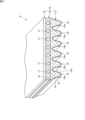
- FIG. 1 is a diagram showing a schematic view of a portion of a V-ribbed belt according to an embodiment of the present invention
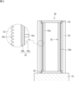
- FIG. 2A to 2C are diagrams for explaining a method of manufacturing the V-ribbed belt shown in FIG. 1 .
- 2A to 2C are diagrams for explaining a method of manufacturing the V-ribbed belt shown in FIG. 1 .
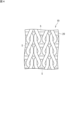
- FIG. 2 is a diagram showing an example of a fibrous material constituting a fibrous material layer. 4 is a conceptual diagram illustrating a surface state of a fibrous material layer.
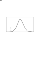
- FIG. FIG. 2 is a conceptual diagram illustrating the molecular weight distribution of a raw rubber component.
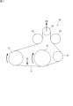
- FIG. 1 is a diagram showing the pulley layout of a belt running test machine for evaluating water-injected transmission capacity.
- FIG. 1 is a diagram showing a pulley layout of a belt running test machine for a durability test.
- FIG. 1 is a schematic diagram showing a portion of a friction transmission belt B according to an embodiment of the present invention.
- This friction transmission belt B is a V-ribbed belt used, for example, in an accessory drive belt transmission device provided in an engine room of an automobile, etc.
- This V-ribbed belt B has, for example, a belt circumference of 700 mm or more and 3000 mm or less, a belt width of 10 mm or more and 36 mm or less, and a belt thickness of 3.5 mm or more and 5.0 mm or less.
- This V-ribbed belt B includes an endless belt body 10.
- the inner peripheral surface of the belt body 10 contacts a pulley.
- the belt body 10 includes a compressed rubber layer 11 located on the inner peripheral side of the belt, an adhesive rubber layer 12 located in the middle, and a back reinforcing fabric 13 located on the outer peripheral side of the belt.
- the compressed rubber layer 11 extends in the length direction of the belt.
- the compressed rubber layer 11 comes into contact with a pulley such as a driving pulley or a driven pulley.
- the compressed rubber layer 11 constitutes a contact portion with the pulley.
- the compressed rubber layer 11 includes a rubber layer main body 14 and a fiber material layer 15. In this V-ribbed belt B, the compressed rubber layer 11 is composed of the rubber layer main body 14 and the fiber material layer 15.
- the rubber layer body 14 is also referred to as a compressed rubber layer body.
- the rubber layer body 14 has a thickness of, for example, 2.0 mm or more and 3.2 mm or less.
- the rubber layer main body 14 is made of a cross-linked product of the rubber composition. In other words, the rubber layer main body 14 is a cross-linked rubber produced by using the rubber composition.
- the rubber composition is produced by mixing a raw rubber component with various compounding agents.
- the rubber composition contains the raw rubber component and various compounding agents.
- Examples of the raw rubber component contained in the rubber composition include ethylene- ⁇ -olefin elastomers such as ethylene-propylene-diene terpolymer (EPDM), ethylene-propylene copolymer (EPM), ethylene-butene copolymer (EBM), and ethylene-octene copolymer (EOM); chloroprene rubber (CR); chlorosulfonated polyethylene rubber (CSM); and hydrogenated acrylonitrile rubber (H-NBR).
- the raw rubber component is preferably one or more of these, and more preferably contains an ethylene- ⁇ -olefin elastomer.
- the main component of the raw rubber component is an ethylene- ⁇ -olefin elastomer.
- the raw rubber component mainly containing an ethylene- ⁇ -olefin elastomer means that the amount of the ethylene- ⁇ -olefin elastomer contained in the raw rubber component is 50% by mass or more of the total amount of the raw rubber component.
- the main component of the raw rubber component is an ethylene- ⁇ -olefin elastomer
- the amount of the ethylene- ⁇ -olefin elastomer contained in the raw rubber component is preferably 70% by mass or more, more preferably 90% by mass or more, and even more preferably 95% by mass or more of the total amount of the raw rubber component.
- the raw rubber component is an ethylene- ⁇ -olefin elastomer.
- the ethylene- ⁇ -olefin elastomer it is preferable to use EPDM.
- the compounding agents that can be contained in the rubber composition include crosslinking agents such as sulfur and organic peroxides, vulcanization accelerators, co-crosslinking agents, antiaging agents, processing aids, plasticizers, process oils, reinforcing agents such as carbon black, and fillers. Of these compounding agents, those that exhibit liquid properties at a temperature of 40°C are liquid compounding agents. Of the compounding agents mentioned above, plasticizers and process oils are liquid compounding agents.
- the plasticizer examples include dialkyl phthalates such as dibutyl phthalate (DBP) and dioctyl phthalate (DOP), dialkyl adipates such as dioctyl adipate (DOA), and dialkyl sebacates such as dioctyl sebacate (DOS).
- the rubber composition may contain one or more of these as the plasticizer.
- the content of the plasticizer is preferably 0.1 parts by mass or more and 40 parts by mass or less, more preferably 0.1 parts by mass or more and 20 parts by mass or less, per 100 parts by mass of the raw rubber component.
- process oils include paraffinic oils, naphthenic oils, and aromatic oils.
- the rubber composition may contain one or more of these as the process oil.
- the content of the process oil is preferably 0.1 parts by mass or more and 40 parts by mass or less, and more preferably 0.1 parts by mass or more and 20 parts by mass or less, per 100 parts by mass of the raw rubber component.
- the main component of the liquid compounding agent is preferably process oil.
- the liquid compounding agent containing process oil as the main component means that the amount of process oil contained in the liquid compounding agent is 50 mass % or more of the total amount of the liquid compounding agent.
- the amount of process oil contained in the liquid compounding agent is preferably 70% by mass or more, more preferably 90% by mass or more, and even more preferably 95% by mass or more of the total amount of the liquid compounding agent. It is particularly preferable that the liquid compounding agent is process oil.
- EPDM is used as the ethylene- ⁇ -olefin elastomer
- the process oil is preferably paraffin-based oil.
- the rubber layer main body 14 is a cross-linked product of a rubber composition.
- the cross-linked product of a rubber composition in other words, cross-linked rubber, is obtained by mixing various compounding agents with the raw rubber components to prepare a rubber composition, pressurizing and heating this rubber composition in a mold, and cross-linking the raw rubber components with a cross-linking agent.
- the fibrous material layer 15 is laminated on the inner circumferential surface of the rubber layer main body 14.
- the fibrous material layer 15 constitutes the inner circumferential surface of the belt main body 10.
- the thickness of the fibrous material layer 15 is, for example, not less than 0.1 mm and not more than 1.5 mm.
- the fiber member layer 15 covers the entire inner circumferential surface of the rubber layer main body 14.
- the fiber member layer 15 may be laminated on the inner circumferential surface so as to cover a portion of the inner circumferential surface.
- the fibrous material layer 15 includes a fibrous material.
- the fibrous material is made of a fabric.
- the fabric include a woven fabric and a knitted fabric.
- the weave of the woven fabric include plain weave, twill weave, satin weave, and variations thereof.
- the knitted fabric include plain weave, rib knit, purl knit, and other variations in the weft knit, and single Denbigh knit, single Van Dyke knit, and other variations in the warp knit.
- the fiber member is preferably a knitted fabric.
- the fibrous member When the fibrous member is a woven fabric, warp and weft yarns are used to form the fibrous member. When the fibrous member is a knitted fabric, knitting yarns are used to form the fibrous member.
- fibers constituting the yarn used to form the woven or knitted fabric include natural fibers such as cellulose-based fibers, wool, and silk, and synthetic fibers such as polyurethane fibers, aliphatic polyamide fibers (nylon 66 fibers), aromatic polyamide fibers (para- and meta-based), polyester fibers, acrylic fibers, and polyvinyl alcohol fibers.
- the woven or knitted fabric may be formed from one type of fiber or two or more types of fibers. From the viewpoint of having good water absorption performance, the fibers constituting the fibrous member are preferably cellulosic fibers.
- a fiber material that has been subjected to an adhesive treatment may be used, or a fiber material that has not been subjected to an adhesive treatment may be used.
- adhesive treatments include a process in which the fiber material is immersed in an epoxy resin solution or an isocyanate resin solution and heated, a process in which the fiber material is immersed in an RFL aqueous solution and heated, and a process in which the fiber material is immersed in rubber glue and dried.
- the adhesive rubber layer 12 is a band with a horizontally elongated rectangular cross section that extends in the belt length direction.
- the thickness of the adhesive rubber layer 12 is, for example, 1.0 mm or more and 2.5 mm or less.
- the adhesive rubber layer 12 is composed of an adhesive rubber layer main body 16 and a core wire 17 that is covered by the adhesive rubber layer main body 16.
- the adhesive rubber layer main body 16 is a cross-linked rubber made using a rubber composition.
- the compressed rubber layer main body 14 and the adhesive rubber layer main body 16 may be made of the same rubber composition or different rubber compositions.
- the core wire 17 is located in the middle of the adhesive rubber layer 12 in the belt thickness direction.
- the core wire 17 is wound to form a spiral with a pitch in the belt width direction and is embedded in the adhesive rubber layer main body 16.
- the core wire 17 is made of twisted yarn of polyamide fiber, polyester fiber, aramid fiber, polyamide fiber, etc.
- the diameter of the core wire 17 is, for example, 0.5 mm or more and 2.5 mm or less.
- the shortest distance between adjacent core wires 17 in the cross section of the adhesive rubber layer 12 is, for example, 0.05 mm or more and 0.20 mm or less.
- the core wire 17 is subjected to one or more of the following adhesive treatments: an adhesive treatment in which the core wire 17 is immersed in an epoxy resin solution or an isocyanate resin solution and heated; an adhesive treatment in which the core wire 17 is immersed in an RFL aqueous solution and then heated; and an adhesive treatment in which the core wire 17 is immersed in rubber cement and then dried.
- the back reinforcing fabric 13 is made of, for example, a cloth material woven in a plain weave, twill weave, satin weave, or the like using yarns such as cotton, polyamide fiber, polyester fiber, aramid fiber, etc., a knitted fabric, a nonwoven fabric, etc.
- the thickness of the back reinforcing fabric 13 is, for example, 0.4 mm or more and 1.2 mm or less.
- the back reinforcing fabric 13 may be subjected to an adhesion treatment in which it is immersed in an RFL aqueous solution and heated before molding in order to impart adhesion to the adhesive rubber layer 12, and/or an adhesion treatment in which rubber cement is coated on the outer peripheral surface of the adhesive rubber layer 12 and dried.
- the back reinforcing fabric 13 may be attached to the adhesive rubber layer 12 via a rubber layer (not shown).
- a back rubber layer having a thickness of, for example, 0.4 mm to 0.8 mm may be used instead of the back reinforcing fabric 13.
- the texture of the woven fabric is preferably transferred to the surface of the back rubber layer from the viewpoint of suppressing noise generation during back driving.
- the back rubber layer is preferably made of a rubber composition that is slightly harder than the adhesive rubber layer main body 16.
- this back rubber layer may be made of the same rubber composition as one or both of the compressed rubber layer main body 14 and the adhesive rubber layer main body 16, or it may be made of a rubber composition different from both of the compressed rubber layer main body 14 and the adhesive rubber layer main body 16.
- the back rubber layer is made of a rubber composition different from that of the adhesive rubber layer main body 16
- each V-shaped rib 18 has a rib height of 2.0 mm to 3.0 mm and a base-to-base width of 1.0 mm to 3.6 mm.
- the number of V-shaped ribs 18 is, for example, 3 to 10 (six in FIG. 1 ).
- the surface of the compressed rubber layer 11 is composed of a fiber material layer 15.
- the surface of the V-rib 18 is composed of a fiber material layer 15.
- the fiber material layer 15 comes into contact with the pulley.
- the surface of the fiber material layer 15 is the contact surface 15a that comes into contact with the pulley.
- the fiber material layer 15 has a contact surface 15a that comes into contact with the pulley.
- FIG. 2 is a diagram for explaining a cross-linking device 30 used in the manufacture of the V-ribbed belt B. As shown in FIG.
- the cross-linking device 30 comprises a base 31, an expansion drum 32, and a mold 33.
- the expansion drum 32 is cylindrical.
- the expansion drum 32 is erected on the base 31.
- the mold 33 is cylindrical.
- the mold 33 is provided outside the expansion drum 32.
- the expansion drum 32 has a drum body 32a and an expansion sleeve 32b.
- the drum body 32a and the expansion sleeve 32b are both cylindrical.
- the expansion sleeve 32b is located outside the drum body 32a.
- the expansion sleeve 32b is made of rubber.
- the expansion sleeve 32b is fitted to the outer periphery of the drum body 32a.
- the drum body 32a has a number of ventilation holes 32c. Each ventilation hole 32c communicates between the inside and the outside of the drum body 32a.
- Both ends of the expansion sleeve 32b are fixed by fixing rings 34.
- the fixing rings 34 seal the gaps between the drum body 32a and the ends of the expansion sleeve 32b.
- the cross-linking device 30 has a pressurizing means.
- the pressurizing means introduces air with adjusted pressure into the inside of the drum body 32a. The air passes through the air vent 32c and is introduced between the drum body 32a and the expansion sleeve 32b. The expansion sleeve 32b expands radially outward. This pressurizes the uncross-linked slab, which will be described later.
- the mold 33 is detachable from the base 31.
- the mold 33 attached to the base 31 is provided concentrically on the outside of the expansion drum 32.
- the die 33 is a die used in manufacturing the V-ribbed belt B.
- a plurality of V-rib forming grooves 33a extending in the circumferential direction are provided on the inner peripheral surface of the die 33 in order to shape the V-ribs 18 of the V-ribbed belt B.
- the plurality of V-rib forming grooves 33a are arranged in parallel in the axial direction (groove width direction). Each V-rib forming groove 33a is formed so as to narrow from the groove mouth toward the groove bottom.
- the shape of the V-rib forming groove 33a corresponds to the shape of the V-rib 18.
- the cross-linking device 30 is equipped with a heating means and a cooling means for the mold 33.
- the temperature of the mold 33 is controlled by the heating means and the cooling means.
- FIGS. 3A and 3B are diagrams for explaining the manufacturing method of V-ribbed belt B.
- each compounding agent is mixed with the raw rubber components, and these are kneaded in a kneading machine such as a kneader or a Banbury mixer to obtain a rubber composition.
- the rubber composition is formed into a sheet shape by calendar molding or the like to prepare an uncrosslinked rubber sheet 14' for the rubber layer main body 14 of the compressed rubber layer 11.
- an uncrosslinked rubber sheet 16' for the rubber layer main body 16 of the adhesive rubber layer 12 is also prepared.
- a fiber member 19 for the fiber member layer 15 and a back reinforcing cloth 13 are prepared, and an adhesive treatment is applied to the fiber member 19 or the back reinforcing cloth 13 as necessary.
- the fiber member 19 is formed into a cylindrical shape in advance.
- the back reinforcing cloth 13 may also be formed into a cylindrical shape in advance.
- a core wire 17 is prepared, and an adhesive treatment is applied to the core wire 17 as necessary.
- the back reinforcing cloth 13 and the uncrosslinked rubber sheet 16' for the adhesive rubber layer main body 16 are wound in that order around a cylindrical drum (not shown) covered with a rubber sleeve 37.
- the core wire 17 is spirally wound around the uncrosslinked rubber sheet 16'
- the uncrosslinked rubber sheet 16' for the adhesive rubber layer main body 16 and the uncrosslinked rubber sheet 14' for the compressed rubber layer main body 14 are further wound in that order.
- a tubular fiber member 19 is placed on top of the uncrosslinked rubber sheet 14' to obtain an uncrosslinked slab S'.
- the uncrosslinked slab S' is removed from the cylindrical drum together with the rubber sleeve 37. As shown in FIG. 3A, the uncrosslinked slab S' is placed on the inner peripheral surface side of the mold 33 together with the rubber sleeve 37. This sets the uncrosslinked slab S' between the mold 33 and the expansion drum 32.
- the mold 33 is heated, and air is introduced between the drum body 32a and the expansion sleeve 32b of the expansion drum 32 through the air hole 32c as shown in FIG. 3B.
- the expansion sleeve 32b is expanded, and the uncrosslinked slab S' is pressed against the mold 33.
- the uncrosslinked rubber sheet 14' flows into the V-rib forming groove 33a while stretching the fiber member 19.
- the fiber member 19, the uncrosslinked rubber sheet 14', the uncrosslinked rubber sheet 16', the cord 17, and the back reinforcing cloth 13 are integrated, and the crosslinking of the raw rubber components of the uncrosslinked rubber sheets 14' and 16' progresses. As a result, a cylindrical belt slab S is formed.
- the belt slab S is a crosslinked product of the uncrosslinked slab S'.
- the forming temperature of the belt slab S is, for example, 100° C. or more and 180° C. or less.
- the forming pressure of the belt slab S is, for example, 0.5 MPa or more and 2.0 MPa or less.
- the forming time of the belt slab S is, for example, 10 minutes or more and 60 minutes or less.
- the belt slab S is removed from the bridging device 30, cut into slices with a predetermined number of ribs 18, and turned over to obtain the V-ribbed belt B.
- Fig. 4 shows an example of the fiber member 19 constituting the fiber member layer 15.
- the fiber member 19 shown in Fig. 4 is a knitted fabric called plain knit or jersey knit.
- the knitted fabric is made by knitting a yarn 20 (knitting yarn). This forms stitches.
- the stitches are gaps that are created when the yarn 20 is knitted.
- woven fabric is made by combining threads (warp threads) and threads (weft threads). This forms the weave.
- the weave is the gap in the woven fabric.
- Nonwoven fabric is made by intertwining many fibers. In nonwoven fabric, the intertwining of the fibers forms the gap. In this way, the fibrous material 19 has a large number of gaps. In other words, the fibrous material 19 has a large number of gaps.
- gap openings there are many gap openings on the surface of the fibrous member 19.
- the portions indicated by the reference character S in Fig. 4 are the gaps of the fibrous member 19 shown in Fig. 4.
- the gap S penetrates the fibrous material 19.
- the gap S is represented as a cylindrical hole penetrating the fibrous material 19.
- the crosslinked slab S' is pressed against the cylindrical die 33, and the uncrosslinked rubber sheets 14', 16' press and stretch the fibrous member 19 while flowing into the V-rib forming groove 33a.
- the fibrous member 19 is laminated on the uncrosslinked rubber sheet 14', i.e., the rubber composition of the rubber layer main body 14.
- the rubber composition has fluidity. When the rubber composition presses the fibrous member 19, a part of the rubber composition penetrates into the gaps S of the fibrous member 19.
- the raw rubber components of the rubber composition are crosslinked, and a rubber member 21 made of a crosslinked product of the rubber composition that has penetrated into the gaps S is formed in the gaps S of the fibrous member 19, as shown in FIG. 3B.
- the fibrous member layer 15 is composed of the fibrous member 19 and the rubber member 21 present in the gaps S of this fibrous member 19.
- the rubber member 21 stretches by threading through the gaps S of the fibrous member 19.
- FIG. 5 shows a schematic diagram of the surface state of the fiber material layer 15 .
- the rubber composition presses the fiber member 19, so that part of the rubber composition that has soaked into the gaps S seeps out onto the surface of the fiber member 19.
- the surface of the fiber member layer 15 is configured with a fiber portion 19a made of the fiber member 19 and a rubber portion 21a made of the rubber member 21.
- the surface of the fiber member layer 15, i.e., the contact surface 15a that comes into contact with the pulley, includes the fiber portion 19a and the rubber portion 21a.
- the rubber member 21 forms part of the contact surface 15a.
- the rubber composition has a certain fluidity, the stronger the force with which the rubber composition presses the fiber member 19, the longer the time that the rubber composition presses the fiber member 19, the higher the fluidity of the rubber composition, and the larger the size of the gaps S in the fiber member 19, the greater the amount of rubber composition that seeps out to the surface. If a large amount of rubber composition has seeped out to the surface, the rubber portion 21a covers the gaps S. If the amount of rubber composition is small, the rubber portion 21a is formed inside the gaps S. If the rubber composition does not reach the opening, the rubber portion 21a will not be formed on the contact surface 15a.
- the proportion of the rubber portion 21a that occupies the contact surface 15a changes depending on the molding conditions, the fluidity of the rubber composition, the specifications of the fiber member 19, etc.
- the proportion of the rubber portion 21a that occupies the contact surface 15a is set appropriately according to the specifications of the friction transmission belt.
- the surface state of the fiber material layer 15 shown in Figure 5 is a state in which rubber portions 21a have been formed in some of the gaps S of the fiber material 19 shown in Figure 4.
- the gaps S where the rubber composition did not reach the openings and rubber portions 21a were not formed are not shown as part of the fiber portion 19a.
- the ratio of the rubber portion 21a occupying the contact surface 15a (hereinafter, rubber occupied area ratio) can be obtained, for example, as follows.
- An observation sample including a part of the surface is taken from the fiber member layer 15 of the V-ribbed belt.
- There is no particular limitation on the size of the surface to be sampled but for example, an observation sample including a rectangular surface having a size of 5 mm in the belt longitudinal direction and 2 mm in the belt width direction is prepared.
- An observation sample is placed on the stage of a microscope (for example, a digital microscope "VHX-6000" manufactured by Keyence Corporation), and the surface is brought into focus.
- a slide glass is pressed against the observation sample from above, and an image of the surface of the fiber material layer 15 is taken.
- the area of each rubber portion 21a included in the observation target area is measured by software built into the microscope.
- the ratio of the total area of the rubber portions 21a to the area of the entire observation target area is obtained as the rubber occupied area ratio.
- the load with which the slide glass presses the surface sample is appropriately set so as not to exceed 1 kg for a surface size of 5 mm x 2 mm.
- This load is preferably set to about 500 g (more specifically, 450 g to 550 g).
- the rubber occupation area ratio thus obtained is preferably 3% or more and 50% or less, from the viewpoint of obtaining good friction and abrasion resistance characteristics.
- the rubber composition that constitutes the rubber layer main body 14 of the compressed rubber layer 11 contains a raw rubber component.
- the raw rubber component is usually an aggregate of polymers having different molecular weights.
- the raw rubber component has a molecular weight distribution.
- Fig. 6 is a conceptual diagram showing the molecular weight distribution of a raw rubber component.
- the horizontal axis of Fig. 6 represents molecular weight (g/mol), with the molecular weight increasing toward the right.
- the vertical axis of Fig. 6 represents the abundance ratio, with the abundance ratio increasing toward the top.
- a raw rubber component usually has the molecular weight distribution shown in Fig. 6. This molecular weight distribution can be obtained, for example, by performing gel permeation chromatography analysis (hereinafter, GPC analysis).
- a polystyrene-equivalent molecular weight distribution measured using a "High Temperature GPC (Alliance GPC/V2000)" manufactured by Nippon Waters Corporation as a measuring instrument under the following conditions is used as the molecular weight distribution of the raw rubber component.
- Detector Differential refractometer
- the arrow L indicates the left tail of the molecular weight distribution. This indicates the presence of polymers with low molecular weights (hereinafter referred to as low molecular weight components) among the polymers that make up the raw rubber component.
- the raw rubber component contains low molecular weight components.
- the contact surface 15a of the friction transmission belt B with the pulley has the rubber portion 21a made of a cross-linked product of the rubber composition soaked into the fiber member 19.
- the rubber portion 21a is made of a cross-linked product of the rubber composition for the rubber layer main body 14.
- the inventors have conducted intensive research focusing on this rubber portion 21a and have found that the friction and wear resistance of the friction transmission belt B is improved by keeping low the total amount of the low molecular weight components of the raw rubber components and the liquid compounding agent contained in the rubber composition of the rubber layer main body 14, and that the friction and wear resistance is deeply related to the presence of low molecular weight components having a molecular weight of 5000 g/mol or less, in particular, and have thus completed the present invention.
- the total amount of the low molecular weight component having a molecular weight of 5000 g/mol or less and the liquid compounding agent, which is obtained by GPC analysis of the raw rubber component is 5.0 mass% or less of the total rubber composition of the rubber layer main body 14.
- the total amount ratio expressed as the ratio of the total amount of the low molecular weight component having a molecular weight of 5000 g/mol or less and the liquid compounding agent to the total rubber composition of the rubber layer main body 14, is 5.0 mass% or less.
- This friction transmission belt B has good water-injection transmission ability, and this good water-injection transmission ability is stably maintained. This friction transmission belt B can achieve improved friction and wear resistance.
- the total amount of the low molecular weight components and the liquid compounding agent is preferably 0.5 mass% or more of the total rubber composition of the rubber layer main body 14, more preferably 1.0 mass% or more, and even more preferably 1.6 mass% or more. From the viewpoint of improving friction and wear resistance, this total amount is preferably 4.9 mass% or less of the total rubber composition, and more preferably 4.2 mass% or less.
- the rubber composition of the rubber layer main body 14 has a kinetic viscosity of the liquid compounding agent, measured at 40° C. in accordance with JIS K 2230, of 480 mm 2 /s or less.
- the liquid compounding agent having a kinetic viscosity of 480 mm2 /s or less effectively improves the fluidity of the rubber composition.
- the rubber portion 21a is stably formed on the contact surface 15a with the pulley. As described above, the total amount of the low molecular weight component of the raw rubber component and the amount of the liquid compounding agent is suppressed to 5.0 mass% or less.
- This friction transmission belt B can further improve the friction and wear resistance.
- the main component of the liquid compounding agent is preferably process oil.
- the total amount of the low molecular weight component having a molecular weight of 5000 g/mol or less contained in the ethylene- ⁇ -olefin elastomer and the amount of the process oil is preferably 5.0 mass% or less.
- the total amount of the low molecular weight component having a molecular weight of 5,000 g/mol or less contained in the EPDM and the amount of the paraffin-based oil is 5.0 mass% or less.
- a V-ribbed belt has been described as an embodiment of the friction transmission belt according to the present invention, but the friction transmission belt according to the embodiment of the present invention is not limited to this and may be a V-belt, a flat belt, etc.
- V-ribbed belts of Examples 1 to 6 and Comparative Examples 1 to 4 were produced and evaluated.
- a knitted fabric was prepared as the fiber material.
- the knitted fabric used is a plain knit (plain knit) fabric made of a urethane elastic yarn covered with a 6-nylon yarn.
- the urethane elastic yarn has a fineness of 22 denier (24.4 dtex), and the 6-nylon yarn has a fineness of 78 denier (86.7 dtex) and 52 filaments.
- the knitted fabric has a knit density of 66 wales/2.54 cm and 70 courses/2.54 cm.
- the knitted fabric has a thickness of 0.52 mm.
- the knitted fabric was immersed in an aqueous RFL solution and dried by heating, thereby forming an RFL coating on the surface of the knitted fabric.
- EPDM1 trade name "Nordel 4640” manufactured by Dow Chemical Co.
- EPDM2 product name “EPT 3070” manufactured by Mitsui Chemicals
- EPDM3 product name "EPT 3091” manufactured by Mitsui Chemicals
- EPDM4 product name "EPT X-4010M” manufactured by Mitsui Chemicals
- GPC analysis was performed on each EPDM under the above-mentioned conditions to measure the amount of low molecular weight components having a molecular weight of 5000 g/mol or less contained in 100 parts by mass of EPDM.
- EPDM1 contained 0 parts by mass of low molecular weight components
- EPDM2 contained 0 parts by mass of low molecular weight components
- EPDM3 contained 0 parts by mass of low molecular weight components
- EPDM4 contained 5 parts by mass of low molecular weight components.
- carbon black (trade name "Asahi #60” manufactured by Asahi Carbon Co., Ltd.), process oil (trade name “Sunflex 2280” manufactured by Nippon Sun Oil Co., Ltd.), zinc oxide (trade name "Zinc Oxide Type 2” manufactured by Sakai Chemical Industry Co., Ltd.), stearic acid (trade name “Stearic Acid” manufactured by Kao Corporation or “Beads Stearic Acid Camellia” manufactured by NOF Corp.), vulcanization accelerator A (trade name "Noccela MSA-G” manufactured by Ouchi Shinko Chemical Co., Ltd.), vulcanization accelerator B (trade name "Suncerer EM2” manufactured by Sanshin Chemical Industry Co., Ltd.), and sulfur (trade name "Oil Sulfur” manufactured by Hosoi Chemical Industry Co., Ltd.) were prepared.
- the compounding agent corresponding to the liquid compounding agent among the materials for the compressed rubber layer main body is process oil.
- a rubber composition was prepared by blending and kneading each material in the amounts shown in Table 1 below. The rubber composition was formed into a sheet having a thickness of 0.7 mm using a roll.
- a rubber composition was prepared by blending and kneading 100 parts by mass of EPDM (product name "EP123” manufactured by JSR Corporation) as a raw rubber component, 50 parts by mass of carbon black (product name "Asahi #60” manufactured by Asahi Carbon Co., Ltd.), 8 parts by mass of process oil (product name "Sunflex 2280” manufactured by Nippon Sun Oil Co., Ltd.), 1 part by mass of stearic acid (product name “Stearic Acid” manufactured by Kao Corporation or product name “Beads Stearic Acid Camellia” manufactured by NOF Corporation), 5 parts by mass of zinc oxide (product name "Zinc Oxide Type 2" manufactured by Sakai Chemical Industry Co., Ltd.), 5 parts by mass of zinc methacrylate (product name "Actor ZMA” manufactured by Kawaguchi Chemical Industry Co., Ltd.), 1 part by mass of vulcanization accelerator (product name "Noccela MSA-G” manufactured
- ⁇ Materials for the core wire As a material for the core wire, a twisted yarn of polyester fiber was prepared, which was immersed in an aqueous solution of RFL and then subjected to an adhesion treatment of heating and drying.
- ⁇ Materials for the back reinforcement fabric As the back reinforcing fabric, a woven fabric made of a cotton-polyester blend yarn was immersed in an aqueous RFL solution, and then subjected to an adhesion treatment of heating and drying.
- Example 1 A V-ribbed belt having a width of 21.36 mm (6 V-ribs) and a circumference of 1,210 mm was produced using the same configuration as the above embodiment, and using the rubber composition of Example 1 shown in Table 1 as the compressed rubber layer main body material, and the above-mentioned fiber member, compressed rubber layer main body material, adhesive rubber layer main body material, core wire, and back reinforcement fabric as described above, by the manufacturing method described with reference to Figures 2 to 3B. This was the V-ribbed belt of Example 1.
- Total amount of low molecular weight component and liquid compounding agent The sum of the amount of low molecular weight components having a molecular weight of 5000 g/mol or less contained in 100 parts by mass of EPDM and the amount of process oil blended relative to 100 parts by mass of EPDM was calculated. This was taken as the total amount of the amount of low molecular weight components having a molecular weight of 5000 g/mol or less obtained by GPC analysis of the raw rubber components and the amount of liquid compounding agents. The total amount of each component shown in Table 1 was calculated.
- Fig. 7 shows the pulley layout of a belt running test machine 50 for evaluating water-injected power transmission capacity.
- reference symbol B denotes a V-ribbed belt.
- This belt running tester 50 has a first driving pulley 51 with a ribbed pulley diameter of 121.6 mm at the bottom left, and a second driving pulley 52 with a ribbed pulley diameter of 141.5 mm to the right of that.
- a first driven pulley 53 with a ribbed pulley diameter of 77.0 mm is provided diagonally above the right of the second driving pulley 52, and a second driven pulley 54 with a ribbed pulley diameter of 61.0 mm is provided above the second driving pulley 52.
- a first idler pulley 55 with a flat pulley diameter of 76.2 mm is provided between the first driving pulley 51 and the second driven pulley 54, and a second idler pulley 56 with a flat pulley diameter of 76.2 mm is provided between the first driven pulley 53 and the second driven pulley 54.
- the second driven pulley 54 is movable up and down and is configured to be able to bear an axial load.
- Each of the V-ribbed belts B produced in the examples and comparative examples was wound around the first and second driving pulleys 51, 52 and the second and second driven pulleys 53, 54 so that the V-rib side was in contact, and the first and second idler pulleys 55, 56 so that the stretched rubber layer side was in contact, and an axial load (dead weight (DW)) of 706 N was applied upward to the second driven pulley 54 to apply belt tension.
- the winding angle of the V-ribbed belt B around the second driving pulley 52 was 39°.
- the first driving pulley 51 was rotated at 800 rpm and the second driving pulley 52 was rotated at 931 rpm in the same direction, thereby forcibly slipping the V-ribbed belt B on the second driving pulley 52.
- Water droplets were also dripped at a rate of 300 ml per minute onto the V-rib surface at the beginning of the winding of the V-ribbed belt B on the right side of the first driving pulley 51.
- the maximum torque generated was measured using a torque meter attached to the second drive pulley 52. This measurement was performed before and after the durability test described below. The absolute value of the difference between the maximum torque before the durability test and the maximum torque after the durability test was calculated to confirm the change in maximum torque. The results are shown in Tables 2 and 3 below. The smaller the change in maximum torque, the more stable the water-injected transmission capacity is maintained and the more excellent the friction and wear resistance properties are.
- FIG. 8 shows a pulley layout of a belt running test machine 60 for a durability test.
- This belt running tester 60 is composed of a pair of a drive ribbed pulley 61 and a driven ribbed pulley 62, both of which have a pulley diameter of 60 mm and are arranged on the left and right.
- V-ribbed belt B was wound around a driving ribbed pulley 61 and a driven ribbed pulley 62 so that the V-rib sides were in contact, and the driving ribbed pulley 61 was pulled sideways so that a dead weight (DW) of 1,177 N was applied, and a rotational load of 3.8 kW was applied to the driven ribbed pulley 62.
- DW dead weight
- a belt running test was carried out in which the drive ribbed pulley 61 was rotated at a rotation speed of 3500 rpm for 96 hours in a room temperature environment (23 ⁇ 5° C.).
- the V-ribbed belt according to the embodiment of the present invention has a small change in maximum torque and achieves improved friction and wear resistance.
- V-ribbed belt disclosed herein is useful, for example, in automobile accessory drive belt transmission devices.
Landscapes
- Engineering & Computer Science (AREA)
- General Engineering & Computer Science (AREA)
- Chemical & Material Sciences (AREA)
- Mechanical Engineering (AREA)
- Textile Engineering (AREA)
- Health & Medical Sciences (AREA)
- Chemical Kinetics & Catalysis (AREA)
- Medicinal Chemistry (AREA)
- Polymers & Plastics (AREA)
- Organic Chemistry (AREA)
Abstract
摩擦伝動ベルトBは、プーリとの接触部分を構成する圧縮ゴム層11を備える。圧縮ゴム層11は、ゴム層本体14と繊維部材層15とを備える。繊維部材層15は、繊維部材19と、繊維部材19の隙間Sに存在するゴム部材21とで構成される。繊維部材層15はプーリと接触する接触面15aを有する。ゴム部材21は接触面15aの一部をなす。ゴム部材21は隙間Sに染み込んだゴム層本体14のゴム組成物の架橋物からなる。ゴム組成物は原料ゴム成分と液状配合剤とを含む。原料ゴム成分のゲル浸透クロマトグラフィー分析により得られる、分子量が5000g/mol以下である低分子量成分の量と、液状配合剤の量との合計量は、ゴム組成物全量の5.0質量%以下である。
Description
本発明は、摩擦伝動ベルトに関する。
本出願は、2023年6月14日出願の日本出願第2023-097418号に基づく優先権を主張し、前記日本出願に記載された全ての記載内容を援用するものである。
本出願は、2023年6月14日出願の日本出願第2023-097418号に基づく優先権を主張し、前記日本出願に記載された全ての記載内容を援用するものである。
従来、エンジン、モーター等の回転動力を伝達する手段として、駆動側及び従動側のそれぞれの回転軸にプーリを固定させて設けると共に、それぞれのプーリにVリブドベルト等の摩擦伝動ベルトを掛け渡す方法が広く用いられている。
摩擦伝動ベルト(以下、伝動ベルト)では、プーリとの接触部分の摩擦係数を制御するために、プーリ接触面を被覆布で被覆することが知られている(例えば、下記の特許文献1)。
例えば自動車の補機駆動ベルト伝動装置として、クランクシャフトプーリ(駆動リブプーリ)、パワーステアリングプーリ及びエアコンプーリ(従動リブプーリ)を含む3つ以上のプーリに、1本のVリブドベルトが巻き掛けられたサーペンタインドライブ方式のものが広く普及している。
自動車の高性能化が進み、Vリブドベルトにおいては耐摩擦摩耗特性の更なる改善が求められている。
自動車の高性能化が進み、Vリブドベルトにおいては耐摩擦摩耗特性の更なる改善が求められている。
本発明は、このような事情に鑑みてなされたものであり、耐摩擦摩耗特性の向上を達成できる、摩擦伝動ベルトの提供を目的とする。
摩擦伝動ベルトの圧縮ゴム層は、ゴム層本体を構成するゴム組成物に繊維部材を被覆することで得られる。ゴム組成物の一部が繊維部材に染み込むため、圧縮ゴム層の表面には、繊維部材に染み込んだゴム組成物の架橋物からなるゴム部が存在する。
発明者は、このゴム部に着目して鋭意検討したところ、上記ゴム組成物に含まれる、原料ゴム成分の低分子量成分と液状配合剤との合計量を少なく抑えることで、摩擦伝動ベルトの耐摩擦摩耗特性が向上すること、そして、耐摩擦摩耗特性には特に、分子量が5000g/mol以下である低分子量成分の存在が深く関与していることを見出し、本発明を完成するに至っている。
発明者は、このゴム部に着目して鋭意検討したところ、上記ゴム組成物に含まれる、原料ゴム成分の低分子量成分と液状配合剤との合計量を少なく抑えることで、摩擦伝動ベルトの耐摩擦摩耗特性が向上すること、そして、耐摩擦摩耗特性には特に、分子量が5000g/mol以下である低分子量成分の存在が深く関与していることを見出し、本発明を完成するに至っている。
本発明の摩擦伝動ベルトは、プーリとの接触部分を構成する圧縮ゴム層を備える。前記圧縮ゴム層は、ゴム組成物の架橋物からなるゴム層本体と、前記ゴム層本体に積層される繊維部材層とを備える。前記繊維部材層は、布帛で構成された繊維部材と、前記繊維部材の隙間に存在するゴム部材とで構成される。前記繊維部材層は前記プーリと接触する接触面を有する。前記ゴム部材は前記接触面の一部をなす。前記ゴム部材は前記隙間に染み込んだ前記ゴム組成物の架橋物からなる。前記ゴム組成物は原料ゴム成分と液状配合剤とを含む。前記原料ゴム成分のゲル浸透クロマトグラフィー分析により得られる、分子量が5000g/mol以下である低分子量成分の量と、前記液状配合剤の量との合計量は、前記ゴム組成物全量の5.0質量%以下である。
上記摩擦伝動ベルトでは、ゴム層本体を構成するゴム組成物の一部が、繊維部材層を構成する繊維部材に染み込む。繊維部材に染み込んだゴム組成物は、ゴム部としてプーリと接触する接触面の一部をなす。この摩擦伝動ベルトでは、ゴム組成物に含まれる、原料ゴム成分の低分子量成分と液状配合剤との合計量が、ゴム組成物全量の5質量以下と少なく抑えられる。この摩擦伝動ベルトでは、耐摩擦摩耗特性が向上する。
上記摩擦伝動ベルトにおいて、JIS K 2230に準拠し40℃で測定される、前記液状配合剤の動粘度は480mm2/s以下であることが好ましい。
この場合、耐摩擦摩耗特性のさらなる向上が図られる。
この場合、耐摩擦摩耗特性のさらなる向上が図られる。
上記摩擦伝動ベルトにおいて、前記原料ゴム成分の主成分は、エチレン-α-オレフィンエラストマーであることが好ましい。
この場合、耐摩擦摩耗特性のさらなる向上が図られる。
この場合、耐摩擦摩耗特性のさらなる向上が図られる。
上記摩擦伝動ベルトにおいて、前記繊維部材は編布であり、前記繊維部材の隙間は前記編布の編目であることが好ましい。
この場合、耐摩擦摩耗特性のさらなる向上が図られる。
この場合、耐摩擦摩耗特性のさらなる向上が図られる。
上記摩擦伝動ベルトはVリブドベルトであることが好ましい。
上述した圧縮ゴム層を備えるVリブドベルトでは、耐摩擦摩耗特性のさらなる向上が図られる。このVリブドベルトは、安定した注水伝動能力を発揮できる。
上述した圧縮ゴム層を備えるVリブドベルトでは、耐摩擦摩耗特性のさらなる向上が図られる。このVリブドベルトは、安定した注水伝動能力を発揮できる。
本発明の摩擦伝動ベルトは耐摩擦摩耗特性の向上を達成できる。
以下、本発明の実施形態について、図面を参照しながら説明する。
(摩擦伝動ベルト)
図1は、本発明の一実施形態に係る摩擦伝動ベルトBの一部を模式的に示す。
この摩擦伝動ベルトBは、例えば、自動車のエンジンルーム内に設けられる補機駆動ベルト伝動装置等に用いられる、Vリブドベルトである。このVリブドベルトBでは、例えば、ベルト周長が700mm以上3000mm以下であり、ベルト幅が10mm以上36mm以下であり、ベルト厚さが3.5mm以上5.0mm以下である。
(摩擦伝動ベルト)
図1は、本発明の一実施形態に係る摩擦伝動ベルトBの一部を模式的に示す。
この摩擦伝動ベルトBは、例えば、自動車のエンジンルーム内に設けられる補機駆動ベルト伝動装置等に用いられる、Vリブドベルトである。このVリブドベルトBでは、例えば、ベルト周長が700mm以上3000mm以下であり、ベルト幅が10mm以上36mm以下であり、ベルト厚さが3.5mm以上5.0mm以下である。
このVリブドベルトBは、無端帯状のベルト本体10を備える。ベルト本体10の内周側の表面がプーリと接触する。
ベルト本体10は、ベルト内周側に位置する圧縮ゴム層11と、中間に位置する接着ゴム層12と、ベルト外周側に位置する背面補強布13とを備える。
ベルト本体10は、ベルト内周側に位置する圧縮ゴム層11と、中間に位置する接着ゴム層12と、ベルト外周側に位置する背面補強布13とを備える。
圧縮ゴム層11はベルト長さ方向にのびる。圧縮ゴム層11は、駆動プーリや従動プーリのようなプーリと接触する。圧縮ゴム層11はプーリとの接触部分を構成する。
圧縮ゴム層11は、ゴム層本体14と繊維部材層15とを備える。このVリブドベルトBでは、圧縮ゴム層11はゴム層本体14と繊維部材層15とで構成される。
圧縮ゴム層11は、ゴム層本体14と繊維部材層15とを備える。このVリブドベルトBでは、圧縮ゴム層11はゴム層本体14と繊維部材層15とで構成される。
ゴム層本体14は、圧縮ゴム層本体とも称される。ゴム層本体14の厚さは、例えば2.0mm以上3.2mm以下である。
ゴム層本体14はゴム組成物の架橋物からなる。言い換えれば、ゴム層本体14はゴム組成物を用いて作製される架橋ゴムである。
ゴム組成物は、原料ゴム成分に種々の配合剤を混ぜて作製される。ゴム組成物は、原料ゴム成分と、種々の配合剤とを含む。
ゴム層本体14はゴム組成物の架橋物からなる。言い換えれば、ゴム層本体14はゴム組成物を用いて作製される架橋ゴムである。
ゴム組成物は、原料ゴム成分に種々の配合剤を混ぜて作製される。ゴム組成物は、原料ゴム成分と、種々の配合剤とを含む。
上記ゴム組成物に含まれる原料ゴム成分としては、例えば、エチレン・プロピレン・ジエン三元共重合体(EPDM)、エチレン-プロピレンコポリマー(EPM)、エチレン-ブテンコポリマー(EBM)、エチレン-オクテンコポリマー(EOM)などのエチレン-α-オレフィンエラストマー;クロロプレンゴム(CR);クロロスルホン化ポリエチレンゴム(CSM);水素添加アクリロニトリルゴム(H-NBR)等が挙げられる。上記原料ゴム成分は、これらのうちの1種又は2種以上を用いることが好ましく、エチレン-α-オレフィンエラストマーを含むことがより好ましい。この場合、原料ゴム成分の主成分がエチレン-α-オレフィンエラストマーであることが好ましい。
原料ゴム成分の主成分がエチレン-α-オレフィンエラストマーであるとは、原料ゴム成分に含まれるエチレン-α-オレフィンエラストマーの量が、原料ゴム成分全量の50質量%以上であることを意味する。
原料ゴム成分の主成分がエチレン-α-オレフィンエラストマーである場合、原料ゴム成分に含まれるエチレン-α-オレフィンエラストマーの量は、原料ゴム成分全量の70質量%以上であることが好ましく、90質量%以上であることがより好ましく、95質量%以上であることがさらに好ましい。原料ゴム成分がエチレン-α-オレフィンエラストマーであることが特に好ましい。エチレン-α-オレフィンエラストマーとしてはEPDMを用いることが好ましい。
原料ゴム成分の主成分がエチレン-α-オレフィンエラストマーであるとは、原料ゴム成分に含まれるエチレン-α-オレフィンエラストマーの量が、原料ゴム成分全量の50質量%以上であることを意味する。
原料ゴム成分の主成分がエチレン-α-オレフィンエラストマーである場合、原料ゴム成分に含まれるエチレン-α-オレフィンエラストマーの量は、原料ゴム成分全量の70質量%以上であることが好ましく、90質量%以上であることがより好ましく、95質量%以上であることがさらに好ましい。原料ゴム成分がエチレン-α-オレフィンエラストマーであることが特に好ましい。エチレン-α-オレフィンエラストマーとしてはEPDMを用いることが好ましい。
上記ゴム組成物に含むことができる配合剤としては、硫黄、有機過酸化物等の架橋剤、加硫促進剤、共架橋剤、老化防止剤、加工助剤、可塑剤、プロセスオイル、カーボンブラックなどの補強剤、充填剤等が挙げられる。これら配合剤のうち、40℃の温度条件下で液体の性状を示す配合剤が液状配合剤である。上述した配合剤のうち、可塑剤及びプロセスオイルが液状配合剤である。
可塑剤としては、例えば、ジブチルフタレート(DBP)、ジオクチルフタレート(DOP)などのジアルキルフタレート、ジオクチルアジペート(DOA)などのジアルキルアジペート、及びジオクチルセバケート(DOS)などのジアルキルセバケートが挙げられる。ゴム組成物は、可塑剤として、これらのうちの1種又は2種以上を含むことができる。ゴム組成物が可塑剤を含む場合、可塑剤の含有量は、原料ゴム成分100質量部に対して、好ましくは0.1質量部以上40質量部以下であり、より好ましくは0.1質量部以上20質量部以下である。
プロセスオイルとしては、例えば、パラフィン系オイル、ナフテン系オイル及び芳香族オイルが挙げられる。ゴム組成物は、プロセスオイルとして、これらのうちの1種又は2種以上を含むことができる。ゴム組成物がプロセスオイルを含む場合、プロセスオイルの含有量は、原料ゴム成分100質量部に対して、好ましくは0.1質量部以上40質量部以下であり、より好ましくは0.1質量部以上20質量部以下である。
原料ゴム成分の主成分がエチレン-α-オレフィンエラストマーである場合、液状配合剤の主成分はプロセスオイルであることが好ましい。
液状配合剤の主成分がプロセスオイルであるとは、液状配合剤に含まれるプロセスオイルの量が、液状配合剤全量の50質量%以上であることを意味する。
液状配合剤の主成分がプロセスオイルである場合、液状配合剤に含まれるプロセスオイルの量は、液状配合剤全量の70質量%以上であることが好ましく、90質量%以上であることがより好ましく、95質量%以上であることがさらに好ましい。液状配合剤がプロセスオイルであることが特に好ましい。エチレン-α-オレフィンエラストマーとしてEPDMを用いる場合、プロセスオイルとしては、パラフィン系オイルが好ましい。
液状配合剤の主成分がプロセスオイルであるとは、液状配合剤に含まれるプロセスオイルの量が、液状配合剤全量の50質量%以上であることを意味する。
液状配合剤の主成分がプロセスオイルである場合、液状配合剤に含まれるプロセスオイルの量は、液状配合剤全量の70質量%以上であることが好ましく、90質量%以上であることがより好ましく、95質量%以上であることがさらに好ましい。液状配合剤がプロセスオイルであることが特に好ましい。エチレン-α-オレフィンエラストマーとしてEPDMを用いる場合、プロセスオイルとしては、パラフィン系オイルが好ましい。
上述したようにゴム層本体14は、ゴム組成物の架橋物である。ゴム組成物の架橋物、言い換えれば、架橋ゴムは、原料ゴム成分に種々の配合剤を混ぜてゴム組成物を作製し、このゴム組成物をモールド内で加圧及び加熱し、架橋剤によって原料ゴム成分を架橋することで得られる。
繊維部材層15は、ゴム層本体14の内周側表面に積層される。繊維部材層15はベルト本体10の内周側表面を構成する。繊維部材層15の厚さは、例えば0.1mm以上1.5mm以下である。
このVリブドベルトBでは、繊維部材層15はゴム層本体14の内周側表面全体を被覆する。繊維部材層15が内周側表面の一部を被覆するように内周側表面に積層されてもよい。
このVリブドベルトBでは、繊維部材層15はゴム層本体14の内周側表面全体を被覆する。繊維部材層15が内周側表面の一部を被覆するように内周側表面に積層されてもよい。
繊維部材層15は繊維部材を含む。繊維部材は布帛で構成される。布帛としては、例えば、織布及び編布が挙げられる。
織布の織物組織としては、例えば、平織、斜文織、朱子織及びこれらの変化組織が挙げられる。編布の編物組織としては、例えば、よこ編みでは、平編、ゴム編、パール編及びその他の変化組織が挙げられ、たて編みでは、シングルデンビー編、シングルバンダイク編及びその他の変化組織が挙げられる。
伸縮性に富んでゴム層本体14を均一に被覆できる観点から、繊維部材は編布であることが好ましい。
織布の織物組織としては、例えば、平織、斜文織、朱子織及びこれらの変化組織が挙げられる。編布の編物組織としては、例えば、よこ編みでは、平編、ゴム編、パール編及びその他の変化組織が挙げられ、たて編みでは、シングルデンビー編、シングルバンダイク編及びその他の変化組織が挙げられる。
伸縮性に富んでゴム層本体14を均一に被覆できる観点から、繊維部材は編布であることが好ましい。
繊維部材が織布で構成される場合、この繊維部材の形成には経糸及び緯糸が用いられる。繊維部材が編布で構成される場合、この繊維部材の形成には編糸が用いられる。
織布又は編布の形成に用いられる糸を構成する繊維としては、例えば、セルロース系繊維、羊毛、絹などの天然繊維;ポリウレタン繊維、脂肪族ポリアミド繊維(ナイロン66繊維)、芳香族ポリアミド繊維(パラ系、メタ系)、ポリエステル繊維、アクリル繊維、ポリビニルアルコール繊維などの合成繊維が挙げられる。織布又は編布は、これらのうちの1種の繊維で形成されてもよく、2種以上の繊維で形成されてもよい。
良好な吸水性能を有する観点から、繊維部材を構成する繊維としては、セルロース系繊維が好ましい。
織布又は編布の形成に用いられる糸を構成する繊維としては、例えば、セルロース系繊維、羊毛、絹などの天然繊維;ポリウレタン繊維、脂肪族ポリアミド繊維(ナイロン66繊維)、芳香族ポリアミド繊維(パラ系、メタ系)、ポリエステル繊維、アクリル繊維、ポリビニルアルコール繊維などの合成繊維が挙げられる。織布又は編布は、これらのうちの1種の繊維で形成されてもよく、2種以上の繊維で形成されてもよい。
良好な吸水性能を有する観点から、繊維部材を構成する繊維としては、セルロース系繊維が好ましい。
繊維部材層15を形成する場合、接着処理が施された繊維部材が用いられてもよく、接着処理が施されていない繊維部材が用いられてもよい。接着処理としては、エポキシ樹脂溶液又はイソシアネート樹脂溶液に繊維部材を浸漬して加熱する処理、RFL水溶液に繊維部材を浸漬して加熱する処理、繊維部材をゴム糊に浸漬して乾燥させる処理等が挙げられる。
接着ゴム層12は、ベルト長さ方向に延びる、断面横長矩形状の帯である。接着ゴム層12の厚さは、例えば1.0mm以上2.5mm以下である。接着ゴム層12は、接着ゴム層本体16と、この接着ゴム層本体16で覆われる心線17とで構成される。
接着ゴム層本体16はゴム組成物を用いて作製される架橋ゴムである。このVリブドベルトBでは、圧縮ゴム層本体14及び接着ゴム層本体16が、同一のゴム組成物で構成されてもよいし、異なるゴム組成物で構成されてもよい。
心線17は、接着ゴム層12のベルト厚さ方向の中間部に位置する。心線17は、ベルト幅方向にピッチを有する螺旋を形成するように巻かれ、接着ゴム層本体16に埋設される。
心線17は、ポリアミド繊維、ポリエステル繊維、アラミド繊維、ポリアミド繊維等の撚り糸で構成される。心線17の直径は、例えば0.5mm以上2.5mm以下である。接着ゴム層12の断面において相互に隣接する心線17どうしの間の最短距離は、例えば0.05mm以上0.20mm以下である。
好ましくは、心線17には、エポキシ樹脂溶液又はイソシアネート樹脂溶液に浸漬して加熱する接着処理、RFL水溶液に浸漬した後に加熱する接着処理、及びゴム糊に浸漬した後に乾燥させる接着処理のうちの1種又は2種以上の接着処理が施される。
好ましくは、心線17には、エポキシ樹脂溶液又はイソシアネート樹脂溶液に浸漬して加熱する接着処理、RFL水溶液に浸漬した後に加熱する接着処理、及びゴム糊に浸漬した後に乾燥させる接着処理のうちの1種又は2種以上の接着処理が施される。
背面補強布13は、例えば、綿、ポリアミド繊維、ポリエステル繊維、アラミド繊維等の糸を用い、平織、綾織、朱子織等に製織した布材料、編布、不織布等により構成される。背面補強布13の厚さは、例えば0.4mm以上1.2mm以下である。
背面補強布13には、接着ゴム層12に対する接着性を付与するために、成形加工前にRFL水溶液に浸漬して加熱する接着処理、及び/又は、接着ゴム層12の外周面にゴム糊をコーティングして乾燥させる接着処理、が施されていてもよい。背面補強布13がゴム層(図示されず)を介して接着ゴム層12に貼り付けられてもよい。
背面補強布13には、接着ゴム層12に対する接着性を付与するために、成形加工前にRFL水溶液に浸漬して加熱する接着処理、及び/又は、接着ゴム層12の外周面にゴム糊をコーティングして乾燥させる接着処理、が施されていてもよい。背面補強布13がゴム層(図示されず)を介して接着ゴム層12に貼り付けられてもよい。
このVリブドベルトBでは、背面補強布13に代えて、厚さが例えば0.4mm以上0.8mm以下の背面ゴム層が用いられてもよい。この場合、背面ゴム層の表面には、背面駆動時の音発生を抑制する観点から、織布の布目が転写されるのが好ましい。ベルト背面と平プーリとの接触により粘着が生じるのを抑制する観点から、背面ゴム層は接着ゴム層本体16よりもやや硬めのゴム組成物で構成されていることが好ましい。
また、背面ゴム層を設ける場合、この背面ゴム層は、圧縮ゴム層本体14及び接着ゴム層本体16の一方又は両方と同一のゴム組成物で構成されてもよいし、圧縮ゴム層本体14及び接着ゴム層本体16のいずれとも異なるゴム組成物で構成されてもよい。
背面ゴム層が接着ゴム層本体16と異なるゴム組成物で構成される場合は、ベルト背面と平プーリとの接触により粘着が生じるのを抑制する観点から、背面ゴム層は接着ゴム層本体16よりもやや硬めのゴム組成物で構成されるのが好ましい。
また、背面ゴム層を設ける場合、この背面ゴム層は、圧縮ゴム層本体14及び接着ゴム層本体16の一方又は両方と同一のゴム組成物で構成されてもよいし、圧縮ゴム層本体14及び接着ゴム層本体16のいずれとも異なるゴム組成物で構成されてもよい。
背面ゴム層が接着ゴム層本体16と異なるゴム組成物で構成される場合は、ベルト背面と平プーリとの接触により粘着が生じるのを抑制する観点から、背面ゴム層は接着ゴム層本体16よりもやや硬めのゴム組成物で構成されるのが好ましい。
図1に示されるように、このVリブドベルトBでは、ベルト本体10の圧縮ゴム層11に、内周側に垂下する複数のVリブ18が構成される。複数のVリブ18は、ベルト長さ方向に延びる、断面略逆三角形状の突条である。複数のVリブ18はベルト幅方向に並設される。
各Vリブ18は、例えば、リブ高さは2.0mm以上3.0mm以下であり、基端間の幅が1.0mm以上3.6mm以下である。Vリブ18の個数は、例えば3個以上10個以下である(図1では6個)。
各Vリブ18は、例えば、リブ高さは2.0mm以上3.0mm以下であり、基端間の幅が1.0mm以上3.6mm以下である。Vリブ18の個数は、例えば3個以上10個以下である(図1では6個)。
このVリブドベルトBでは、圧縮ゴム層11の表面は繊維部材層15で構成される。Vリブ18の表面は繊維部材層15で構成される。このVリブドベルトBでは、繊維部材層15がプーリと接触する。繊維部材層15の表面はプーリと接触する接触面15aである。言い換えれば、繊維部材層15はプーリと接触する接触面15aを有する。
(VリブドベルトBの製造方法)
次に、VリブドベルトBの製造方法が図面を参照しながら説明される。本発明の一実施形態に係るVリブドベルトBは従来公知の方法で製造される。
図2は、VリブドベルトBの製造で用いる架橋装置30を説明するための図である。
次に、VリブドベルトBの製造方法が図面を参照しながら説明される。本発明の一実施形態に係るVリブドベルトBは従来公知の方法で製造される。
図2は、VリブドベルトBの製造で用いる架橋装置30を説明するための図である。
架橋装置30は、基台31と膨張ドラム32と金型33とを備える。膨張ドラム32は円柱状である。膨張ドラム32は基台31の上に立設される。金型33は円筒状である。金型33は膨張ドラム32の外側に設けられる。
膨張ドラム32は、ドラム本体32aと膨張スリーブ32bとを有する。ドラム本体32a及び膨張スリーブ32bは共に円筒状である。膨張スリーブ32bはドラム本体32aの外側に位置する。膨張スリーブ32bはゴム製である。膨張スリーブ32bはドラム本体32aの外周に嵌め合わされる。
ドラム本体32aは多数の通気孔32cを有する。各通気孔32cは、ドラム本体32aの内部と外部とを連通する。膨張スリーブ32bの両端部はそれぞれ、固定リング34によって固定される。固定リング34は、ドラム本体32aと膨張スリーブ32bの端部との間の隙間を密封する。
ドラム本体32aは多数の通気孔32cを有する。各通気孔32cは、ドラム本体32aの内部と外部とを連通する。膨張スリーブ32bの両端部はそれぞれ、固定リング34によって固定される。固定リング34は、ドラム本体32aと膨張スリーブ32bの端部との間の隙間を密封する。
図示されないが、架橋装置30は加圧手段を有する。加圧手段は、ドラム本体32aの内部に、圧力を調整した空気を導入する。空気は、通気孔32cを通り、ドラム本体32aと膨張スリーブ32bとの間に導入される。膨張スリーブ32bが径方向外向きに膨張する。これにより、後述する、未架橋スラブが加圧される。
金型33は基台31に対して脱着可能である。基台31に取り付けられた金型33は、膨張ドラム32の外側に同心状に設けられる。
金型33は、VリブドベルトBの製造に用いられる金型である。金型33の内周面には、VリブドベルトBのVリブ18を形づけるために、周方向にのびる複数のVリブ形成溝33aが設けられる。複数のVリブ形成溝33aは軸方向(溝幅方向)に並列する。各Vリブ形成溝33aは、溝口から溝底に向かって幅狭になるように形成される。Vリブ形成溝33aの形状はVリブ18の形状に対応する。
金型33は、VリブドベルトBの製造に用いられる金型である。金型33の内周面には、VリブドベルトBのVリブ18を形づけるために、周方向にのびる複数のVリブ形成溝33aが設けられる。複数のVリブ形成溝33aは軸方向(溝幅方向)に並列する。各Vリブ形成溝33aは、溝口から溝底に向かって幅狭になるように形成される。Vリブ形成溝33aの形状はVリブ18の形状に対応する。
図示されないが、架橋装置30は、金型33の加熱手段及び冷却手段を備える。加熱手段及び冷却手段により金型33の温度が制御される。
図3A及び図3Bは、VリブドベルトBの製造方法を説明するための図である。
実施形態に係るVリブドベルトBの製造方法では、まず、原料ゴム成分に各配合剤を配合し、これらを、ニーダー、バンバリーミキサー等の混練機で混練し、ゴム組成物が得られる。ゴム組成物をカレンダー成形等によってシート状に成形して、圧縮ゴム層11のゴム層本体14用の未架橋ゴムシート14’が作製される。同様に、接着ゴム層12のゴム層本体16用の未架橋ゴムシート16’も作製される。繊維部材層15のための繊維部材19と、背面補強布13とが準備され、必要に応じて繊維部材19又は背面補強布13に接着処理が施される。この製造方法では、繊維部材19は予め筒状に形成される。背面補強布13も、予め筒状に形成されていてもよい。心線17が準備され、必要に応じて心線17に接着処理が施される。
次いで、ゴムスリーブ37を被せた円筒ドラム(図示されず)に、背面補強布13と、接着ゴム層本体16用の未架橋ゴムシート16’とが順に巻き付けられる。未架橋ゴムシート16’の上から心線17を螺旋状に巻き付けた後、さらに接着ゴム層本体16用の未架橋ゴムシート16’と圧縮ゴム層本体14用の未架橋ゴムシート14’とが順に巻き付けられる。未架橋ゴムシート14’の上に筒状の繊維部材19を被せて、未架橋スラブS’が得られる。
次いで、ゴムスリーブ37とともに未架橋スラブS’が円筒ドラムから外される。図3Aに示されるように、ゴムスリーブ37とともに未架橋スラブS’が金型33の内周面側に配置される。これにより、金型33と膨張ドラム32との間に未架橋スラブS’がセットされる。
次いで、金型33を加熱すると共に、図3Bに示すように、膨張ドラム32のドラム本体32aと膨張スリーブ32bとの間に通気孔32cを通じて空気が導入される。膨張スリーブ32bを膨張させて、未架橋スラブS’が金型33に対して押し付けられる。未架橋ゴムシート14’は、繊維部材19を伸張させながらVリブ形成溝33aに流入する。繊維部材19、未架橋ゴムシート14’、未架橋ゴムシート16’、心線17、及び背面補強布13が一体化するとともに、未架橋ゴムシート14’,16’の原料ゴム成分の架橋が進行する。これにより、円筒状のベルトスラブSが形成される。ベルトスラブSは、未架橋スラブS’の架橋物である。
ベルトスラブSの成形温度は、例えば、100℃以上180℃以下である。ベルトスラブSの成形圧力は、例えば、0.5MPa以上2.0MPa以下である。ベルトスラブSの成形時間は、例えば、10分以上60分以下である。
ベルトスラブSの成形温度は、例えば、100℃以上180℃以下である。ベルトスラブSの成形圧力は、例えば、0.5MPa以上2.0MPa以下である。ベルトスラブSの成形時間は、例えば、10分以上60分以下である。
そして、架橋装置30からベルトスラブSを取り出し、ベルトスラブSを所定のリブ18の個数毎に輪切りし表裏を裏返すことで、VリブドベルトBが得られる。
図4は、繊維部材層15を構成する繊維部材19の一例を示す。図4が示す繊維部材19は平編又は天竺編と呼ばれる編布である。編布は糸20(編糸)を編んで作られる。これにより編目が構成される。編目は、糸20を編んだときにできる隙間である。
図示されないが、織布は糸(経糸)と糸(緯糸)とを組み合わせて作られる。これにより織目が構成される。織目は織布の隙間である。不織布は多数の繊維を絡み合わせて構成される。不織布では、繊維同士の絡み合いが隙間を構成する。
このように繊維部材19は多数の隙間を有する。言い換えれば、繊維部材19には多数の隙間が存在する。
図示されないが、織布は糸(経糸)と糸(緯糸)とを組み合わせて作られる。これにより織目が構成される。織目は織布の隙間である。不織布は多数の繊維を絡み合わせて構成される。不織布では、繊維同士の絡み合いが隙間を構成する。
このように繊維部材19は多数の隙間を有する。言い換えれば、繊維部材19には多数の隙間が存在する。
繊維部材19の表面には、多数の隙間の開口部が存在する。図4において符号Sで示される部分が、この図4に示された繊維部材19の隙間である。
隙間Sは繊維部材19を貫通する。以降の説明では、説明の便宜のために、隙間Sは繊維部材19を貫通する円筒状の孔として表される。
隙間Sは繊維部材19を貫通する。以降の説明では、説明の便宜のために、隙間Sは繊維部材19を貫通する円筒状の孔として表される。
前述したように、摩擦伝動ベルトBの製造方法では、架橋スラブS’が円筒金型33に対して押し付けられ、未架橋ゴムシート14’,16’が繊維部材19を押圧して伸張させながらVリブ形成溝33aに流入する。
例えば図3Aに示されるように、繊維部材19は未架橋ゴムシート14’、すなわち、ゴム層本体14のゴム組成物に積層される。ゴム組成物は流動性を有する。ゴム組成物が繊維部材19を押圧することで、ゴム組成物の一部が繊維部材19の隙間Sに染み込む。その後、ゴム組成物の原料ゴム成分が架橋するので、繊維部材19の隙間Sには、図3Bに示されるように、隙間Sに染み込んだゴム組成物の架橋物からなるゴム部材21が形成される。繊維部材層15は、繊維部材19と、この繊維部材19の隙間Sに存在するゴム部材21とで構成される。ゴム部材21は繊維部材19の隙間Sを縫ってのびる。
例えば図3Aに示されるように、繊維部材19は未架橋ゴムシート14’、すなわち、ゴム層本体14のゴム組成物に積層される。ゴム組成物は流動性を有する。ゴム組成物が繊維部材19を押圧することで、ゴム組成物の一部が繊維部材19の隙間Sに染み込む。その後、ゴム組成物の原料ゴム成分が架橋するので、繊維部材19の隙間Sには、図3Bに示されるように、隙間Sに染み込んだゴム組成物の架橋物からなるゴム部材21が形成される。繊維部材層15は、繊維部材19と、この繊維部材19の隙間Sに存在するゴム部材21とで構成される。ゴム部材21は繊維部材19の隙間Sを縫ってのびる。
図5は、繊維部材層15の表面状態を模式的に表す。
前述したように、繊維部材19の表面には、多数の隙間Sの開口部が存在する。摩擦伝動ベルトBの製造方法では、ゴム組成物が繊維部材19を押圧するので、隙間Sに染み込んだゴム組成物の一部が繊維部材19の表面に染み出す。繊維部材層15の表面には、繊維部材19からなる繊維部19aと、上記ゴム部材21からなるゴム部21aとが構成される。繊維部材層15の表面、すなわちプーリと接触する接触面15aは、繊維部19aとゴム部21aとを備える。ゴム部材21は接触面15aの一部をなす。
前述したように、繊維部材19の表面には、多数の隙間Sの開口部が存在する。摩擦伝動ベルトBの製造方法では、ゴム組成物が繊維部材19を押圧するので、隙間Sに染み込んだゴム組成物の一部が繊維部材19の表面に染み出す。繊維部材層15の表面には、繊維部材19からなる繊維部19aと、上記ゴム部材21からなるゴム部21aとが構成される。繊維部材層15の表面、すなわちプーリと接触する接触面15aは、繊維部19aとゴム部21aとを備える。ゴム部材21は接触面15aの一部をなす。
ゴム組成物が所定の流動性を有している間は、ゴム組成物が繊維部材19を押圧する力が強いほど、ゴム組成物が繊維部材19を押圧する時間が長いほど、ゴム組成物の流動性が高いほど、そして繊維部材19の隙間Sの大きさが大きいほど、表面に染み出すゴム組成物の量は増加する。表面に染み出したゴム組成物の量が多い場合は、ゴム部21aは隙間Sを覆う。ゴム組成物の量が少ない場合は、ゴム部21aが隙間Sの内側に構成される。ゴム組成物が開口部にまで到達しなければ、接触面15aにゴム部21aは形成されない。成型条件、ゴム組成物の流動性、繊維部材19の仕様等によって、接触面15aを占めるゴム部21aの割合は変化する。接触面15aを占めるゴム部21aの割合は、摩擦伝動ベルトの仕様に応じて適宜設定される。
図5に示された繊維部材層15の表面状態は、図4に示された繊維部材19の隙間Sの一部にゴム部21aが形成された状態である。図5においては、ゴム組成物が開口部にまで到達せず、ゴム部21aが形成されなかった隙間Sは、繊維部19aの一部とし図示していない。
接触面15aを占めるゴム部21aの割合(以下、ゴム占有面積比率)は、例えば、次のようにして得られる。
Vリブドベルトの繊維部材層15から表面の一部を含む観察サンプルがサンプリングされる。サンプリングされる表面の大きさに特に制限はないが、例えば、ベルト長手方向に5mm、ベルト幅方向に2mmの大きさを有する四角形状の表面を含む観察サンプルが準備される。
マイクロスコープ(例えば、キーエンス社製のデジタルマイクロスコープ「VHX-6000」)のステージに観察サンプルがセットされ、表面に焦点が合わせられる。
観察サンプルの上部からスライドガラスを押し当て、繊維部材層15の表面が撮影される。撮影された表面画像に基づいて、観察対象領域に含まれる各ゴム部21aの面積が、マイクロスコープに内蔵されたソフトによって計測される。これにより、ゴム部21aの総面積の、観察対象領域全体の面積に対する比率が、ゴム占有面積比率として得られる。
このゴム占有面積比率の測定においては、スライドガラスによって表面サンプルを押し当てる荷重は、5mm×2mmの表面の大きさに対して、1kgを超えないように適宜設定される。この荷重は500g程度(詳細には450g以上550g以下)に設定されるのが好ましい。
このようにして得られるゴム占有面積比率は、良好な耐摩擦摩耗特性が得られる観点から、3%以上50%以下であることが好ましい。
Vリブドベルトの繊維部材層15から表面の一部を含む観察サンプルがサンプリングされる。サンプリングされる表面の大きさに特に制限はないが、例えば、ベルト長手方向に5mm、ベルト幅方向に2mmの大きさを有する四角形状の表面を含む観察サンプルが準備される。
マイクロスコープ(例えば、キーエンス社製のデジタルマイクロスコープ「VHX-6000」)のステージに観察サンプルがセットされ、表面に焦点が合わせられる。
観察サンプルの上部からスライドガラスを押し当て、繊維部材層15の表面が撮影される。撮影された表面画像に基づいて、観察対象領域に含まれる各ゴム部21aの面積が、マイクロスコープに内蔵されたソフトによって計測される。これにより、ゴム部21aの総面積の、観察対象領域全体の面積に対する比率が、ゴム占有面積比率として得られる。
このゴム占有面積比率の測定においては、スライドガラスによって表面サンプルを押し当てる荷重は、5mm×2mmの表面の大きさに対して、1kgを超えないように適宜設定される。この荷重は500g程度(詳細には450g以上550g以下)に設定されるのが好ましい。
このようにして得られるゴム占有面積比率は、良好な耐摩擦摩耗特性が得られる観点から、3%以上50%以下であることが好ましい。
前述したように、圧縮ゴム層11のゴム層本体14をなすゴム組成物は、原料ゴム成分を含む。原料ゴム成分は通常、異なる分子量を有するポリマーの集合体である。原料ゴム成分は分子量分布を有する。
図6は、原料ゴム成分の分子量分布を表す概念図である。図6の横軸は分子量(g/mol)を表し、右側ほど分子量が大きい。図6の縦軸は存在比率を表し、上側ほど存在比率は高い。原料ゴム成分は通常、この図6に示された分子量分布を有する。この分子量分布は、例えばゲル浸透クロマトグラフィー分析(以下、GPC分析)を行うことで得られる。
本開示においては、日本ウォーターズ社製の「高温GPC(アライアンスGPC/V2000)」を測定機器として用い、以下の条件で測定された、ポリスチレン換算の分子量分布が原料ゴム成分の分子量分布として用いられる。
温度:140℃
溶媒:1,2,4-トリクロロベンゼン(TCB)
流速:1mL/min
サンプル濃度:0.1%
検出器:示差屈折率計
本開示においては、日本ウォーターズ社製の「高温GPC(アライアンスGPC/V2000)」を測定機器として用い、以下の条件で測定された、ポリスチレン換算の分子量分布が原料ゴム成分の分子量分布として用いられる。
温度:140℃
溶媒:1,2,4-トリクロロベンゼン(TCB)
流速:1mL/min
サンプル濃度:0.1%
検出器:示差屈折率計
図6において、矢印Lは分子量分布の左側の裾の部分を指す。この部分は、原料ゴム成分を構成するポリマーのうち、低い分子量を有するポリマー(以下、低分子量成分)の存在を示す。原料ゴム成分は低分子量成分を含む。
前述したように、摩擦伝動ベルトBのプーリとの接触面15aには、繊維部材19に染み込んだゴム組成物の架橋物からなるゴム部21aが存在する。このゴム部21aは、ゴム層本体14のためのゴム組成物の架橋物からなる。
発明者は、このゴム部21aに着目して鋭意検討したところ、ゴム層本体14のゴム組成物に含まれる、原料ゴム成分の低分子量成分と液状配合剤との合計量を少なく抑えることで、摩擦伝動ベルトBの耐摩擦摩耗特性が向上すること、そして、耐摩擦摩耗特性には特に、分子量が5000g/mol以下である低分子量成分の存在が深く関与していることを見出し、本発明を完成するに至っている。
発明者は、このゴム部21aに着目して鋭意検討したところ、ゴム層本体14のゴム組成物に含まれる、原料ゴム成分の低分子量成分と液状配合剤との合計量を少なく抑えることで、摩擦伝動ベルトBの耐摩擦摩耗特性が向上すること、そして、耐摩擦摩耗特性には特に、分子量が5000g/mol以下である低分子量成分の存在が深く関与していることを見出し、本発明を完成するに至っている。
この摩擦伝動ベルトBでは、原料ゴム成分のGPC分析により得られる、分子量が5000g/mol以下である低分子量成分の量と、液状配合剤の量との合計量が、ゴム層本体14のゴム組成物全量の5.0質量%以下である。言い換えれば、分子量が5000g/mol以下である低分子量成分の量と、液状配合剤の量との合計量の、ゴム層本体14のゴム組成物全量に対する比率で表される、合計量比率は5.0質量%以下である。これにより、接触面15aの一部をなすゴム部21aが適度な強度を有する摩擦伝動ベルトBが得られる。接触面15aの状態変化が抑えられるので、繊維部材19を被覆したことにより付与される摩擦係数が、安定に維持される。この摩擦伝動ベルトBは良好な注水伝動能力を有し、この良好な注水伝動能力が安定に保持される。
この摩擦伝動ベルトBは、耐摩擦摩耗特性の向上を達成できる。
この摩擦伝動ベルトBは、耐摩擦摩耗特性の向上を達成できる。
耐摩擦摩耗特性の観点においては、上述の低分子量成分の量と、液状配合剤の量との合計量は少ないほど好ましいが、低分子量成分及び液状配合剤はゴム組成物の加工特性の向上に貢献する。この観点から、低分子量成分の量と液状配合剤の量との合計量は、ゴム層本体14のゴム組成物全量の0.5質量%以上が好ましく、1.0質量%以上がより好ましく、1.6質量%以上がさらに好ましい。耐摩擦摩耗特性の向上の観点から、この合計量は、ゴム組成物全量の4.9質量%以下が好ましく、4.2質量%以下がより好ましい。
この摩擦伝動ベルトBでは、ゴム層本体14のゴム組成物において、JIS K 2230に準拠し40℃で測定される、液状配合剤の動粘度が480mm2/s以下であることが好ましい。
480mm2/s以下の動粘度を有する液状配合剤は、ゴム組成物の流動性を効果的に向上させる。この摩擦伝動ベルトBでは、プーリとの接触面15aにゴム部21aが安定に形成される。前述したように、原料ゴム成分の低分子量成分の量と、液状配合剤の量との合計量は5.0質量%以下に抑えられる。この摩擦伝動ベルトBは耐摩擦摩耗特性の一層の向上を図ることができる。
480mm2/s以下の動粘度を有する液状配合剤は、ゴム組成物の流動性を効果的に向上させる。この摩擦伝動ベルトBでは、プーリとの接触面15aにゴム部21aが安定に形成される。前述したように、原料ゴム成分の低分子量成分の量と、液状配合剤の量との合計量は5.0質量%以下に抑えられる。この摩擦伝動ベルトBは耐摩擦摩耗特性の一層の向上を図ることができる。
前述したように、この摩擦伝動ベルトBでは、ゴム層本体14のゴム組成物において、原料ゴム成分の主成分がエチレン-α-オレフィンエラストマーである場合、液状配合剤の主成分はプロセスオイルであることが好ましい。この場合、耐摩擦摩耗特性の一層の向上が図れる観点から、エチレン-α-オレフィンエラストマーが含む、分子量が5000g/mol以下である低分子量成分の量と、プロセスオイルの量との合計量が5.0質量%以下であることが好ましい。
原料ゴム成分がEPDMであり、プロセスオイルがパラフィン系オイルである場合、耐摩擦摩耗特性の一層の向上が図れる観点から、EPDMが含む、分子量が5000g/mol以下である低分子量成分の量と、パラフィン系オイルの量との合計量が5.0質量%以下であることが好ましい。
原料ゴム成分がEPDMであり、プロセスオイルがパラフィン系オイルである場合、耐摩擦摩耗特性の一層の向上が図れる観点から、EPDMが含む、分子量が5000g/mol以下である低分子量成分の量と、パラフィン系オイルの量との合計量が5.0質量%以下であることが好ましい。
ここまで、本発明の実施形態にかかる摩擦伝動ベルトとしてVリブドベルトの実施形態を説明したが、本発明の実施形態にかかる摩擦伝動ベルトは、これに限られず、Vベルト、平ベルト等であっても良い。
以下、実施例によって本発明をさらに具体的に説明するが、本発明は以下の実施例に限定されるものではない。
ここでは、実施例1~6及び比較例1~4のVリブドベルトを作製し、評価した。
ここでは、実施例1~6及び比較例1~4のVリブドベルトを作製し、評価した。
<繊維部材層のための材料>
繊維部材層の形成のために、繊維部材として編布を用意した。
使用した編布は、ウレタン弾性糸を6-ナイロン糸にてカバリングした糸を用いた平編(天竺編)の編布である。ウレタン弾性糸の繊度は22デニール(24.4dtex)であり、6-ナイロン糸は繊度が78デニール(86.7dtex)で且つフィラメント数が52本である。また、ニット布の編みの密度は、ウェールが66本/2.54cm、コースが70本/2.54cmである。ニット布の厚さは0.52mmである。
この編布に対して接着処理として、RFL水溶液に編布を浸漬して加熱乾燥する処理を行うことにより、編布の表面にRFL被膜を形成した。
RFL水溶液は次のようにして調整した。
レゾルシン(R)とホルマリン(F)とを混合し、水酸化ナトリウム水溶液を加えて攪拌し、RF初期縮合物(R/Fモル比=1/1.5)を得た。そして、RF初期縮合物にVPラテックス(L)をRF/L質量比=1/8となるよう混合し、更に、水を加えて固形分濃度20%となるよう調整した後、24時間攪拌を行ってRFL水溶液を得た。
繊維部材層の形成のために、繊維部材として編布を用意した。
使用した編布は、ウレタン弾性糸を6-ナイロン糸にてカバリングした糸を用いた平編(天竺編)の編布である。ウレタン弾性糸の繊度は22デニール(24.4dtex)であり、6-ナイロン糸は繊度が78デニール(86.7dtex)で且つフィラメント数が52本である。また、ニット布の編みの密度は、ウェールが66本/2.54cm、コースが70本/2.54cmである。ニット布の厚さは0.52mmである。
この編布に対して接着処理として、RFL水溶液に編布を浸漬して加熱乾燥する処理を行うことにより、編布の表面にRFL被膜を形成した。
RFL水溶液は次のようにして調整した。
レゾルシン(R)とホルマリン(F)とを混合し、水酸化ナトリウム水溶液を加えて攪拌し、RF初期縮合物(R/Fモル比=1/1.5)を得た。そして、RF初期縮合物にVPラテックス(L)をRF/L質量比=1/8となるよう混合し、更に、水を加えて固形分濃度20%となるよう調整した後、24時間攪拌を行ってRFL水溶液を得た。
<圧縮ゴム層本体のための材料>
原料ゴム成分として以下に示す5種類のEPDMを準備した。
・EPDM1(DOW CHEMICAL社製の商品名「Nordel 4640」)
・EPDM2(三井化学社製の商品名「EPT 3070」)
・EPDM3(三井化学社製の商品名「EPT 3091」)
・EPDM4(三井化学社製の商品名「EPT X-4010M」)
各EPDMについて、上述した条件にてGPC分析を行い、EPDM100質量部に含まれる、分子量が5000g/mol以下である低分子量成分の量を計測した。その結果、EPDM1では0質量部、EPDM2では0質量部、EPDM3では0質量部そしてEPDM4では5質量部の低分子量成分が含まれていた。
配合剤として、カーボンブラック(旭カーボン社製の商品名「旭#60」)、プロセスオイル(日本サン石油社製の商品名「サンフレックス2280」)、酸化亜鉛(堺化学工業社製の商品名「酸化亜鉛二種」)、ステアリン酸(花王社製の商品名「ステアリン酸」又は日油社製の商品名「ビーズ ステアリン酸 ツバキ」)、加硫促進剤A(大内新興化学社製の商品名「ノクセラーMSA-G」)、加硫促進剤B(三新化学工業社製の商品名「サンセラーEM2」)及び硫黄(細井化学工業社製の商品名「オイルサルファ」)を準備した。圧縮ゴム層本体のための材料のうち液状配合剤に該当する配合剤はプロセスオイルである。
下記の表1に示した配合量で各材料を配合し混練して、ゴム組成物を調製した。ゴム組成物はロールを用いて厚さ0.7mmのシート状に成形した。
原料ゴム成分として以下に示す5種類のEPDMを準備した。
・EPDM1(DOW CHEMICAL社製の商品名「Nordel 4640」)
・EPDM2(三井化学社製の商品名「EPT 3070」)
・EPDM3(三井化学社製の商品名「EPT 3091」)
・EPDM4(三井化学社製の商品名「EPT X-4010M」)
各EPDMについて、上述した条件にてGPC分析を行い、EPDM100質量部に含まれる、分子量が5000g/mol以下である低分子量成分の量を計測した。その結果、EPDM1では0質量部、EPDM2では0質量部、EPDM3では0質量部そしてEPDM4では5質量部の低分子量成分が含まれていた。
配合剤として、カーボンブラック(旭カーボン社製の商品名「旭#60」)、プロセスオイル(日本サン石油社製の商品名「サンフレックス2280」)、酸化亜鉛(堺化学工業社製の商品名「酸化亜鉛二種」)、ステアリン酸(花王社製の商品名「ステアリン酸」又は日油社製の商品名「ビーズ ステアリン酸 ツバキ」)、加硫促進剤A(大内新興化学社製の商品名「ノクセラーMSA-G」)、加硫促進剤B(三新化学工業社製の商品名「サンセラーEM2」)及び硫黄(細井化学工業社製の商品名「オイルサルファ」)を準備した。圧縮ゴム層本体のための材料のうち液状配合剤に該当する配合剤はプロセスオイルである。
下記の表1に示した配合量で各材料を配合し混練して、ゴム組成物を調製した。ゴム組成物はロールを用いて厚さ0.7mmのシート状に成形した。
<接着ゴム層本体のための材料>
EPDM(JSR社製の商品名「EP123」)を原料ゴム成分とし、この原料ゴム成分100質量部に対して、カーボンブラック(旭カーボン社製の商品名「旭#60」)50質量部、プロセスオイル(日本サン石油社製の商品名「サンフレックス2280」)8質量部、ステアリン酸(花王社製の商品名「ステアリン酸」又は日油社製の商品名「ビーズ ステアリン酸 ツバキ」)1質量部、酸化亜鉛(堺化学工業社製の商品名「酸化亜鉛二種」)5質量部、メタクリル酸亜鉛(川口化学工業社製の商品名「アクターZMA」)5質量部、加硫促進剤(大内新興化学社製の商品名「ノクセラーMSA-G」)1質量部、加硫促進剤(三新化学工業社製の商品名「サンセラーEM2」)3質量部、そして、硫黄(細井化学工業社製の商品名「オイルサルファ」)1.5質量部を、配合して混練したゴム組成物を調製した。ゴム組成物はロールを用いて厚さ0.45mmのシート状に成形した。
EPDM(JSR社製の商品名「EP123」)を原料ゴム成分とし、この原料ゴム成分100質量部に対して、カーボンブラック(旭カーボン社製の商品名「旭#60」)50質量部、プロセスオイル(日本サン石油社製の商品名「サンフレックス2280」)8質量部、ステアリン酸(花王社製の商品名「ステアリン酸」又は日油社製の商品名「ビーズ ステアリン酸 ツバキ」)1質量部、酸化亜鉛(堺化学工業社製の商品名「酸化亜鉛二種」)5質量部、メタクリル酸亜鉛(川口化学工業社製の商品名「アクターZMA」)5質量部、加硫促進剤(大内新興化学社製の商品名「ノクセラーMSA-G」)1質量部、加硫促進剤(三新化学工業社製の商品名「サンセラーEM2」)3質量部、そして、硫黄(細井化学工業社製の商品名「オイルサルファ」)1.5質量部を、配合して混練したゴム組成物を調製した。ゴム組成物はロールを用いて厚さ0.45mmのシート状に成形した。
<心線のための材料>
心線のための材料として、ポリエステル繊維の撚り糸を準備し、これをRFL水溶液に浸漬し、その後、加熱乾燥する接着処理を行ったものを用意した。
心線のための材料として、ポリエステル繊維の撚り糸を準備し、これをRFL水溶液に浸漬し、その後、加熱乾燥する接着処理を行ったものを用意した。
<背面補強布のための材料>
背面補強布として、綿ポリエステル混紡糸を用いた織布をRFL水溶液に浸漬し、その後、加熱乾燥する接着処理を行ったものを用意した。
背面補強布として、綿ポリエステル混紡糸を用いた織布をRFL水溶液に浸漬し、その後、加熱乾燥する接着処理を行ったものを用意した。
[実施例1]
上記実施形態と同様の構成を有し、圧縮ゴム層本体材料として、表1に示した実施例1のゴム組成物を使用し、繊維部材、圧縮ゴム層本体材料、接着ゴム層本体材料、心線及び背面補強布として上述したものを使用し、図2~図3Bを参照しながら説明した製造方法で、幅21.36mm(Vリブの個数が6個)、周長1210mmのVリブドベルトを作製し、これを実施例1のVリブドベルトとした。
上記実施形態と同様の構成を有し、圧縮ゴム層本体材料として、表1に示した実施例1のゴム組成物を使用し、繊維部材、圧縮ゴム層本体材料、接着ゴム層本体材料、心線及び背面補強布として上述したものを使用し、図2~図3Bを参照しながら説明した製造方法で、幅21.36mm(Vリブの個数が6個)、周長1210mmのVリブドベルトを作製し、これを実施例1のVリブドベルトとした。
[実施例2~6及び比較例1~4]
圧縮ゴム層本体材料を上述の表1に示される通りとした他は実施例1と同様にして、実施例2~6及び比較例1~4のVリブドベルト(幅=21.36mm(Vリブの個数が6個)、周長=1210mm)を作製した。
圧縮ゴム層本体材料を上述の表1に示される通りとした他は実施例1と同様にして、実施例2~6及び比較例1~4のVリブドベルト(幅=21.36mm(Vリブの個数が6個)、周長=1210mm)を作製した。
<低分子量成分と液状配合剤との合計量>
EPDM100質量部に含まれる、分子量が5000g/mol以下である低分子量成分の量と、EPDM100質量部に対するプロセスオイルの配合量との合計を算出した。これを、原料ゴム成分のGPC分析により得られる、分子量が5000g/mol以下である低分子量成分の量と、液状配合剤の量との合計量とした。
上記表1に示された各成分の配合量の合計を算出した。これをゴム組成物全量とし、分子量が5000g/mol以下である低分子量成分の量と、液状配合剤の量との合計量の、ゴム組成物全量に対する比率を求めた。その結果が、下記の表2及び3における「合計量比率」の欄に示されている。
EPDM100質量部に含まれる、分子量が5000g/mol以下である低分子量成分の量と、EPDM100質量部に対するプロセスオイルの配合量との合計を算出した。これを、原料ゴム成分のGPC分析により得られる、分子量が5000g/mol以下である低分子量成分の量と、液状配合剤の量との合計量とした。
上記表1に示された各成分の配合量の合計を算出した。これをゴム組成物全量とし、分子量が5000g/mol以下である低分子量成分の量と、液状配合剤の量との合計量の、ゴム組成物全量に対する比率を求めた。その結果が、下記の表2及び3における「合計量比率」の欄に示されている。
<耐摩耗性の評価>
JIS K6264-2に準拠して、荷重を9.8N、回転速度を48rpm、回転時間を30分とし、室温下でテーバー摩耗試験を行い、摩耗量を求めた。表1に示された組成のゴム組成物を用いて、テーバー摩耗試験のための試験片を作製した。摩耗量に基づいて、質量減少率を算出した。その結果が、下記の表2及び3に示されている。数値が小さいほど耐摩耗性に優れる。
JIS K6264-2に準拠して、荷重を9.8N、回転速度を48rpm、回転時間を30分とし、室温下でテーバー摩耗試験を行い、摩耗量を求めた。表1に示された組成のゴム組成物を用いて、テーバー摩耗試験のための試験片を作製した。摩耗量に基づいて、質量減少率を算出した。その結果が、下記の表2及び3に示されている。数値が小さいほど耐摩耗性に優れる。
<注水伝動能力の評価>
図7は、注水伝動能力評価用ベルト走行試験機50のプーリレイアウトを示す。図7中、符号BはVリブドベルトである。
図7は、注水伝動能力評価用ベルト走行試験機50のプーリレイアウトを示す。図7中、符号BはVリブドベルトである。
このベルト走行試験機50は、向かって左下にプーリ径が121.6mmのリブプーリの第一駆動プーリ51が設けられ、その右方にプーリ径が141.5mmのリブプーリの第二駆動プーリ52が設けられている。第二駆動プーリ52の右斜め上方にはプーリ径が77.0mmのリブプーリの第一従動プーリ53が設けられ、第二駆動プーリ52の上方にはプーリ径が61.0mmのリブプーリの第二従動プーリ54が設けられている。第一駆動プーリ51と第二従動プーリ54との間にはプーリ径が76.2mmの平プーリの第一アイドラプーリ55が設けられ、第一従動プーリ53と第二従動プーリ54との間にはプーリ径が76.2mmの平プーリの第二アイドラプーリ56が設けられている。第二従動プーリ54は、上下に可動に設けられており、軸荷重を負荷できるように構成されている。
実施例及び比較例で作製したVリブドベルトBのそれぞれについて、Vリブ側が接触するように、第一及び第二駆動プーリ51,52並びに第二及び第二従動プーリ53,54に巻き掛けるとともに、伸張ゴム層側が接触するように、第一及び第二アイドラプーリ55,56に巻き掛け、上方に706Nの軸荷重(デッドウェイト(DW))を第二従動プーリ54にかけてベルト張力を与えた。VリブドベルトBの第二駆動プーリ52への巻き掛かり角度は39°であった。次いで、21℃の温度雰囲気下、第一駆動プーリ51を800rpm及び第二駆動プーリ52を931rpmのそれぞれの回転数で同一方向に回転させ、それにより第二駆動プーリ52上においてVリブドベルトBを強制的にスリップさせた。また、第一駆動プーリ51の右側のVリブドベルトBの巻き掛かり始めの部分のVリブ表面には1分間に300mlの割合で水滴を滴下した。そして、第二駆動プーリ52に設けたトルクメータにより、発生トルクの最大値(最大トルク)を計測した。この計測を、次に示す耐久試験の前後で行った。耐久試験前の最大トルクと耐久試験後の最大トルクの差との絶対値を算出し、最大トルクの変化を確認した。その結果が下記の表2及び3に示されている。その結果が、最大トルクの変化が小さいほど、注水伝動能力が安定に保持され、耐摩擦摩耗特性に優れる。
<耐久試験>
図8は、耐久試験のためのベルト走行試験機60のプーリレイアウトを示す。
このベルト走行試験機60は、左右に配されたプーリ径60mmの一対の駆動リブプーリ61及び従動リブプーリ62からなる。
図8は、耐久試験のためのベルト走行試験機60のプーリレイアウトを示す。
このベルト走行試験機60は、左右に配されたプーリ径60mmの一対の駆動リブプーリ61及び従動リブプーリ62からなる。
実施例及び比較例で作製したVリブドベルトのそれぞれについて、Vリブ側が接触するように駆動リブプーリ61と従動リブプーリ62とにVリブドベルトBを巻き掛け、1177Nのデッドウェイト(DW)が負荷されるように駆動リブプーリ61を側方に引っ張るとともに、3.8kWの回転負荷を従動リブプーリ62にかけた。
室温環境下(23±5℃)で駆動リブプーリ61を3500rpmの回転速度で96時間回転させるベルト走行試験を実施した。
室温環境下(23±5℃)で駆動リブプーリ61を3500rpmの回転速度で96時間回転させるベルト走行試験を実施した。
表2及び3に示した通り、本発明の実施形態に係るVリブドベルトによれば、最大トルクの変化が小さく、耐摩擦摩耗特性の向上が達成される。
本開示のVリブドベルトは、例えば、自動車の補機構駆動ベルト伝動装置等に有用である。
10 ベルト本体
11 圧縮ゴム層
12 接着ゴム層
13 背面補強布
14 ゴム層本体(圧縮ゴム層本体)
15 繊維部材層
16 接着ゴム層本体
17 心線
18 Vリブ
19 繊維部材
21 ゴム部材
30 架橋装置
14’、16’ 未架橋ゴムシート
50、60 走行試験機
B 摩擦伝動ベルト(Vリブドベルト)
S 隙間
11 圧縮ゴム層
12 接着ゴム層
13 背面補強布
14 ゴム層本体(圧縮ゴム層本体)
15 繊維部材層
16 接着ゴム層本体
17 心線
18 Vリブ
19 繊維部材
21 ゴム部材
30 架橋装置
14’、16’ 未架橋ゴムシート
50、60 走行試験機
B 摩擦伝動ベルト(Vリブドベルト)
S 隙間
Claims (5)
- プーリとの接触部分を構成する圧縮ゴム層を備える摩擦伝動ベルトであって、
前記圧縮ゴム層が、ゴム組成物の架橋物からなるゴム層本体と、前記ゴム層本体に積層される繊維部材層とを備え、
前記繊維部材層が、布帛で構成された繊維部材と、前記繊維部材の隙間に存在するゴム部材とで構成され、
前記繊維部材層が、前記プーリと接触する接触面を有し、
前記ゴム部材が前記接触面の一部をなし、
前記ゴム部材が前記隙間に染み込んだ前記ゴム組成物の架橋物からなり、
前記ゴム組成物が、原料ゴム成分と液状配合剤とを含み、
前記原料ゴム成分のゲル浸透クロマトグラフィー分析により得られる、分子量が5000g/mol以下である低分子量成分の量と、前記液状配合剤の量との合計量が、前記ゴム組成物全量の5.0質量%以下である、
摩擦伝動ベルト。 - JIS K 2230に準拠し40℃で測定される、前記液状配合剤の動粘度が480mm2/s以下である、
請求項1に記載の摩擦伝動ベルト。 - 前記原料ゴム成分の主成分が、エチレン-α-オレフィンエラストマーである、
請求項1又は2に記載の摩擦伝動ベルト。 - 前記繊維部材が編布であり、前記繊維部材の隙間が前記編布の編目である、
請求項1から3のいずれか一項に記載の摩擦伝動ベルト。 - Vリブドベルトである、
請求項1から4のいずれか一項に記載の摩擦伝動ベルト。
Priority Applications (1)
| Application Number | Priority Date | Filing Date | Title |
|---|---|---|---|
| JP2024536292A JPWO2024257827A1 (ja) | 2023-06-14 | 2024-06-13 |
Applications Claiming Priority (2)
| Application Number | Priority Date | Filing Date | Title |
|---|---|---|---|
| JP2023097418 | 2023-06-14 | ||
| JP2023-097418 | 2023-06-14 |
Publications (1)
| Publication Number | Publication Date |
|---|---|
| WO2024257827A1 true WO2024257827A1 (ja) | 2024-12-19 |
Family
ID=93852208
Family Applications (1)
| Application Number | Title | Priority Date | Filing Date |
|---|---|---|---|
| PCT/JP2024/021499 Ceased WO2024257827A1 (ja) | 2023-06-14 | 2024-06-13 | 摩擦伝動ベルト |
Country Status (2)
| Country | Link |
|---|---|
| JP (1) | JPWO2024257827A1 (ja) |
| WO (1) | WO2024257827A1 (ja) |
Citations (2)
| Publication number | Priority date | Publication date | Assignee | Title |
|---|---|---|---|---|
| JP2017106617A (ja) * | 2015-11-27 | 2017-06-15 | 三ツ星ベルト株式会社 | 摩擦伝動ベルト及びその製造方法 |
| JP6505335B1 (ja) * | 2017-10-02 | 2019-04-24 | バンドー化学株式会社 | 伝動ベルト |
Family Cites Families (2)
| Publication number | Priority date | Publication date | Assignee | Title |
|---|---|---|---|---|
| JPH0693143A (ja) * | 1992-09-11 | 1994-04-05 | Ube Ind Ltd | 熱可塑性エラストマー組成物 |
| JP6831943B1 (ja) * | 2019-10-24 | 2021-02-17 | 三ツ星ベルト株式会社 | 摩擦伝動ベルトおよびその製造方法 |
-
2024
- 2024-06-13 JP JP2024536292A patent/JPWO2024257827A1/ja active Pending
- 2024-06-13 WO PCT/JP2024/021499 patent/WO2024257827A1/ja not_active Ceased
Patent Citations (2)
| Publication number | Priority date | Publication date | Assignee | Title |
|---|---|---|---|---|
| JP2017106617A (ja) * | 2015-11-27 | 2017-06-15 | 三ツ星ベルト株式会社 | 摩擦伝動ベルト及びその製造方法 |
| JP6505335B1 (ja) * | 2017-10-02 | 2019-04-24 | バンドー化学株式会社 | 伝動ベルト |
Also Published As
| Publication number | Publication date |
|---|---|
| JPWO2024257827A1 (ja) | 2024-12-19 |
Similar Documents
| Publication | Publication Date | Title |
|---|---|---|
| JP6342760B2 (ja) | 摩擦伝動ベルト | |
| KR100907780B1 (ko) | 마찰전동벨트 및 그 제조방법 | |
| JP4768893B2 (ja) | 摩擦伝動ベルト | |
| KR101495453B1 (ko) | 마찰전동벨트 | |
| JP5302074B2 (ja) | Vリブドベルト及びその製造方法 | |
| JPWO2015045255A1 (ja) | Vベルト及びその製造方法 | |
| JP6505335B1 (ja) | 伝動ベルト | |
| KR20160064176A (ko) | 평 벨트 및 그 제조방법 | |
| KR101917709B1 (ko) | V 리브드 벨트 | |
| KR20220125679A (ko) | V리브형 벨트 | |
| WO2010109532A1 (ja) | 摩擦伝動ベルト | |
| JP7551520B2 (ja) | 摩擦伝動ベルト | |
| JP7487137B2 (ja) | Vリブドベルト | |
| JP2025105954A (ja) | 摩擦伝動ベルト | |
| JP2025107406A (ja) | 伝動ベルト | |
| WO2024257827A1 (ja) | 摩擦伝動ベルト | |
| JP4966824B2 (ja) | 摩擦伝動ベルト | |
| KR102745454B1 (ko) | 마찰 전동 벨트 | |
| US20200124136A1 (en) | Transmission belt and method for producing same | |
| WO2024257823A1 (ja) | 摩擦伝動ベルト | |
| JP6530877B1 (ja) | 摩擦伝動ベルト | |
| JP6383135B1 (ja) | 伝動ベルト及びその製造方法 | |
| JP2004190686A (ja) | 動力伝動用ベルト | |
| JP2005188689A (ja) | Vリブドベルト |
Legal Events
| Date | Code | Title | Description |
|---|---|---|---|
| WWE | Wipo information: entry into national phase |
Ref document number: 2024536292 Country of ref document: JP |
|
| 121 | Ep: the epo has been informed by wipo that ep was designated in this application |
Ref document number: 24823442 Country of ref document: EP Kind code of ref document: A1 |
|
| NENP | Non-entry into the national phase |
Ref country code: DE |