WO2024257975A1 - 트랙터용 작물 수확 장치 - Google Patents
트랙터용 작물 수확 장치 Download PDFInfo
- Publication number
- WO2024257975A1 WO2024257975A1 PCT/KR2023/020326 KR2023020326W WO2024257975A1 WO 2024257975 A1 WO2024257975 A1 WO 2024257975A1 KR 2023020326 W KR2023020326 W KR 2023020326W WO 2024257975 A1 WO2024257975 A1 WO 2024257975A1
- Authority
- WO
- WIPO (PCT)
- Prior art keywords
- transport
- plate
- roller
- pair
- inlet
- Prior art date
- Legal status (The legal status is an assumption and is not a legal conclusion. Google has not performed a legal analysis and makes no representation as to the accuracy of the status listed.)
- Ceased
Links
Images


Classifications
-
- A—HUMAN NECESSITIES
- A01—AGRICULTURE; FORESTRY; ANIMAL HUSBANDRY; HUNTING; TRAPPING; FISHING
- A01D—HARVESTING; MOWING
- A01D43/00—Mowers combined with apparatus performing additional operations while mowing
- A01D43/06—Mowers combined with apparatus performing additional operations while mowing with means for collecting, gathering or loading mown material
- A01D43/077—Mowers combined with apparatus performing additional operations while mowing with means for collecting, gathering or loading mown material with auxiliary means, e.g. fans, for transporting the mown crop
-
- A—HUMAN NECESSITIES
- A01—AGRICULTURE; FORESTRY; ANIMAL HUSBANDRY; HUNTING; TRAPPING; FISHING
- A01B—SOIL WORKING IN AGRICULTURE OR FORESTRY; PARTS, DETAILS, OR ACCESSORIES OF AGRICULTURAL MACHINES OR IMPLEMENTS, IN GENERAL
- A01B59/00—Devices specially adapted for connection between animals or tractors and agricultural machines or implements
- A01B59/06—Devices specially adapted for connection between animals or tractors and agricultural machines or implements for machines mounted on tractors
- A01B59/064—Devices specially adapted for connection between animals or tractors and agricultural machines or implements for machines mounted on tractors for connection to the front of the tractor
-
- A—HUMAN NECESSITIES
- A01—AGRICULTURE; FORESTRY; ANIMAL HUSBANDRY; HUNTING; TRAPPING; FISHING
- A01D—HARVESTING; MOWING
- A01D33/00—Accessories for digging harvesters
- A01D33/10—Crop collecting devices, with or without weighing apparatus
-
- A—HUMAN NECESSITIES
- A01—AGRICULTURE; FORESTRY; ANIMAL HUSBANDRY; HUNTING; TRAPPING; FISHING
- A01D—HARVESTING; MOWING
- A01D34/00—Mowers; Mowing apparatus of harvesters
- A01D34/01—Mowers; Mowing apparatus of harvesters characterised by features relating to the type of cutting apparatus
- A01D34/412—Mowers; Mowing apparatus of harvesters characterised by features relating to the type of cutting apparatus having rotating cutters
- A01D34/63—Mowers; Mowing apparatus of harvesters characterised by features relating to the type of cutting apparatus having rotating cutters having cutters rotating about a vertical axis
- A01D34/64—Mowers; Mowing apparatus of harvesters characterised by features relating to the type of cutting apparatus having rotating cutters having cutters rotating about a vertical axis mounted on a vehicle, e.g. a tractor, or drawn by an animal or a vehicle
- A01D34/66—Mowers; Mowing apparatus of harvesters characterised by features relating to the type of cutting apparatus having rotating cutters having cutters rotating about a vertical axis mounted on a vehicle, e.g. a tractor, or drawn by an animal or a vehicle with two or more cutters
Definitions
- the present invention relates to a crop harvesting device for a tractor, and more specifically, to a crop harvesting device for a tractor which can improve crop introduction performance by minimizing stagnation and clogging of crops by adjusting the width and height of an introduction portion when cutting crops and introducing the cut crops into a treatment tank.
- auxiliary agricultural tools such as detachable agricultural harvesters
- power-driven agricultural machines such as cultivators and tractors
- These agricultural harvesters can save labor when harvesting crops, and can harvest grains, vegetables, and fruits, depending on the type.
- Conventional agricultural harvesters can harvest a variety of crops including corn, sudan grass, and ryegrass, but they have the problem of crops frequently becoming clogged due to the fixed width of the inlet without considering the size, thickness, and properties of the crops.
- Patent Document 1 Korean Patent No. 10-1282927 (registered on July 1, 2013)
- the present invention has been made to solve the above-described problems, and the purpose of the present invention is to provide a crop harvesting device for a tractor capable of improving crop introduction performance by minimizing stagnation and clogging of crops by adjusting the width and height of an introduction portion when cutting crops and introducing the cut crops into a treatment tank.
- a crop harvesting device for a tractor may include a cutting frame coupled to a front end of the tractor and including a first coupling portion and a second coupling portion, a cutting portion installed at the first coupling portion and including a cutting blade that rotates around a first rotation axis that is perpendicular to the ground, and a cutting module that includes a guide portion coupled to the cutting portion so as to protrude forward, a transport portion installed at the second coupling portion and including a transport blade that rotates around a second rotation axis that is acute to the ground, and a transport module including a pair of inlet width adjusting portions that are installed to face each other on the transport portion, and a roller module including a roller fixing portion, one end and the other end of which are respectively coupled to the first coupling portion centered on the second coupling portion, and a roller portion that is connected to the roller fixing portion and is disposed between the pair of inlet width adjusting portions.
- the roller fixing member may include a first roller fixing plate coupled to the first coupling member, a roller fixing extension plate extending from the first roller fixing plate, and a second roller fixing plate extending from the roller fixing extension plate and coupled to the first coupling member.
- the roller section may include a pair of height-adjusting members, one end of which is connected to a first surface of the roller-fixing extension plate, a pair of roller rotation members, one end of which is connected to a second surface of the roller-fixing extension plate and the other end of which is connected to each of the other ends of the pair of height-adjusting members, and a roller member disposed between the pair of roller rotation members and axially connected between each end and the other end of the pair of roller rotation members.
- the inlet width adjustment unit may include an inlet fixed plate coupled to the transport unit and including a first slit hole, an inlet movable plate coupled to the inlet fixed plate and including a second slit hole, and an inlet width adjustment member having one end coupled to the transport unit and the other end connected to the inlet movable plate to push the inlet movable plate.
- the inlet fixed plate may further include a pair of plate connecting pieces protruding in the direction of the transport section and a side insertion hole formed between the pair of plate connecting pieces
- the inlet movable plate may further include a plate rotating piece protruding in the direction of the transport section and inserted into the side insertion hole
- the inlet width adjusting section may further include a side connecting member connecting the pair of plate connecting pieces and the plate rotating piece.
- the transport blade may include a first transport blade and a second transport blade
- the transport section may further include a first transport rotary drum to which the first transport blade is coupled and a second transport rotary drum coupled to a lower portion of the first transport rotary drum and to which the second transport blade is coupled.
- a crop harvesting device for a tractor provides the following effects.
- the present invention has the effect of improving crop introduction performance by minimizing stagnation and clogging of crops by adjusting the width and height of the introduction portion when cutting crops and introducing the cut crops into a treatment tank.
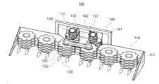
- FIG. 1 is a perspective view illustrating a crop harvesting device for a tractor according to an embodiment of the present invention.
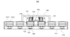
- FIG. 2 is a front view illustrating a crop harvesting device for a tractor according to an embodiment of the present invention.
- FIG. 3 is a rear view illustrating a crop harvesting device for a tractor according to an embodiment of the present invention.
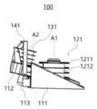
- FIG. 4 is a side view illustrating a crop harvesting device for a tractor according to an embodiment of the present invention.
- Figures 5 to 7 are perspective views illustrating a transport module of a crop harvesting device for a tractor according to an embodiment of the present invention.
- FIG. 8 is a partially exploded perspective view illustrating a transport module of a crop harvesting device for a tractor according to an embodiment of the present invention.
- FIG. 9 is a perspective view for explaining an introduction fixing plate and an introduction moving plate of an introduction width adjusting unit of a crop harvesting device for a tractor according to an embodiment of the present invention.
- FIG. 10 is an exploded perspective view illustrating an introduction fixing plate and an introduction moving plate of an introduction width adjusting unit of a crop harvesting device for a tractor according to an embodiment of the present invention.
- FIG. 11 is a perspective view illustrating a roller module of a crop harvesting device for a tractor according to an embodiment of the present invention.
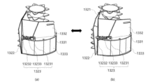
- FIGS. 12 and 13 are plan views for explaining the operation of a crop flow and inlet width control unit using a crop harvesting device for a tractor according to an embodiment of the present invention.
- first, second, etc. may be used to describe various components, but the components should not be limited by the terms. The terms are used only to distinguish one component from another.
- FIGS. 1 to 13 a crop harvesting device for a tractor according to embodiments of the present invention will be described in detail with reference to FIGS. 1 to 13.
- FIG. 1 is a perspective view illustrating a crop harvesting device for a tractor according to an embodiment of the present invention
- FIG. 2 is a front view illustrating a crop harvesting device for a tractor according to an embodiment of the present invention
- FIG. 3 is a rear view illustrating a crop harvesting device for a tractor according to an embodiment of the present invention
- FIG. 4 is a side view illustrating a crop harvesting device for a tractor according to an embodiment of the present invention.
- a crop harvesting device (100) for a tractor can be attached to a tractor (not shown) and used to harvest crops.
- the crop harvesting device (100) for a tractor can include a cutting frame (110), a cutting module (120), a transport module (130), and a roller module (140).
- the cutting frame (110) can be coupled to the front end of the tractor.
- the cutting frame (110) can include a first coupling portion (111), a second coupling portion (112), and a third coupling portion (113).
- the first connecting portion (111) may have a T-shaped structure when viewed from a plane, and a triangular structure when viewed from the side.
- a cutting portion (121) and a guide portion (122) of a cutting module (120) may be installed on one part of the first connecting portion (111), that is, the front end.
- a second connecting portion (112) may be coupled to another part of the first connecting portion (111), that is, the rear end.
- the second coupling part (112) can be coupled to the first coupling part (111) at another part of the first coupling part (111), that is, at a part adjacent to the tractor.
- a transport part (131) of a transport module (130) and a pair of inlet width adjusting parts (132) can be installed in the second coupling part (112).
- the third connecting part (113) can be connected to the lower surface of the second connecting part (112).
- the third connecting part (113) is a part to which the tractor is connected and can be formed in a form that can be attached and detached to the front end of the tractor.
- the cutting module (120) can be installed in the first connecting portion (111) of the shear frame (110).
- the cutting module (120) can cut the crop and guide the movement of the crop.
- the cutting module (120) can include a cutting portion (121) and a guide portion (122).
- the cutting unit (121) may include a cutting blade (1211) that rotates around a first rotation axis (A1 in FIG. 4) that is perpendicular to the ground and a cutting rotary drum (1212) to which the cutting blade (1211) is coupled.
- the cutting blade (1211) can rotate around the first rotation axis (A1 in FIG. 4) to cut the crop and simultaneously move the cut crop to the transport module (130).
- the cutting blade (1211) can include a plurality of teeth.
- a plurality of cutting blades (1211) can be connected to a cutting rotating drum (1212) at regular intervals.
- the cutting blade (1211) may include a first cutting blade having first teeth formed at a first interval, a second cutting blade having second teeth formed at a second interval narrower than the first interval, and a third cutting blade having third teeth formed at a third interval narrower than the second interval.
- the first cutting blade, the second cutting blade, and the third cutting blade may be sequentially coupled to the cutting rotary drum (1212).
- the cutting rotary drum (1212) may be configured in multiples and installed in a 1:1 correspondence with the cutting blade (1211), or may be configured in one and multiple cutting blades (1211) may be installed at a set interval.
- a first rotation axis (A1) may be located at the center of the cutting rotary drum (1212).
- the cutting rotary drum (1212) may be formed in a cylindrical shape.
- the guide part (122) can be combined with the cutting part (121).
- the guide part (122) is formed to protrude in the forward direction of the tractor and can guide the positional movement of the crop so that the crop can be smoothly drawn toward the cutting part (121).
- the guide member (122) may be formed to be adjustable in length and angle according to the length, thickness, etc. of the crop.
- the guide member (122) may be formed to be adjustable in length in the forward direction of the tractor in a telescopic manner.
- the guide member (122) may be formed to be adjustable in angle in a direction perpendicular to the forward direction of the tractor by including at least one joint.
- the transport module (130) can be installed in the second connecting portion (112) of the shear frame (110).
- the transport module (130) can re-cut the cut crop and simultaneously move the crop to a crop storage space (not shown) inside the tractor.
- the transport module (130) can include a transport section (131), a pair of inlet width adjustment sections (132), and a transport catch section (133).
- FIGS. 5 to 7 are perspective views illustrating a transport module of a crop harvesting device for a tractor according to an embodiment of the present invention
- FIG. 8 is a partially exploded perspective view illustrating a transport module of a crop harvesting device for a tractor according to an embodiment of the present invention
- FIG. 9 is a perspective view illustrating an introduction fixing plate and an introduction moving plate of an introduction width adjusting unit of a crop harvesting device for a tractor according to an embodiment of the present invention
- FIG. 10 is an exploded perspective view illustrating an introduction fixing plate and an introduction moving plate of an introduction width adjusting unit of a crop harvesting device for a tractor according to an embodiment of the present invention.
- the transport unit (131) may include a transport blade (1311, 1312) that rotates about a second rotational axis (A2 in FIG. 4) that is at an acute angle to the ground.
- the transport blades (1311, 1312) may include a first transport blade (1311) and a second transport blade (1312).
- the first transport blade (1311) and the second transport blade (1312) can rotate around the second rotation axis (A2 of FIG. 4) to re-cut the crop cut at the cutting section (121) and simultaneously move the crop.
- the first transport blade (1311) and the second transport blade (1312) can include a plurality of teeth.
- the tooth spacing of the first transport blade (1311) can be formed narrower than the tooth spacing of the second transport blade (1312).
- the size (diameter) of the first transport blade (1311) can be formed smaller than the size (diameter) of the second transport blade (1312).
- the transport unit (131) may further include a first transport rotation drum (1313) and a second transport rotation drum (1314).
- the first transport rotary drum (1313) may be coupled with first transport blades (1311) at a predetermined interval.
- the first transport rotary drum (1313) may be configured in multiples and installed in a 1:1 correspondence with the first transport blades (1311), or may be configured in one and multiple first transport blades (1311) may be installed at a predetermined interval.
- a second rotation axis (A2) may be located at the center of the first transport rotary drum (1313).
- the first transport rotary drum (1313) may be formed in a cylindrical shape.
- the second transport rotary drum (1314) may be coupled with second transport blades (1312) at a predetermined interval.
- the second transport rotary drum (1314) may be configured in multiples and installed in a 1:1 correspondence with the second transport blades (1312), or may be configured in one and multiple second transport blades (1312) may be installed at a predetermined interval.
- a second rotation axis (A2) may be located at the center of the second transport rotary drum (1314).
- the second transport rotary drum (1314) may be formed in a cylindrical shape.
- a pair of inlet width adjusting parts (132) can be installed facing each other on the transport part (131).
- a pair of inlet width adjusting parts (132) can be operated manually or automatically to adjust the width of the space into which crops are introduced.
- a pair of inlet width adjusting members (132) may include an inlet fixing plate (1321), an inlet moving plate (1322), an inlet width adjusting member (1323), and a single connecting member (1324).
- the inlet fixing plate (1321) is coupled to the transport member (131) and may include a first slit hole (13211).
- the first slit hole (13211) is formed at a certain interval and the first transport blade (1311) and the second transport blade (1312) can pass through while rotating.
- the upper end of the inlet fixing plate (1321) can be connected to the first capturing plate (1332) of the transport capturing unit (133).
- the inlet fixing plate (1321) can partially wrap around the rear of the first transport blade (1311) and the first transport rotating drum (1313) by being connected to the first capturing plate (1332).
- the lower end of the inlet fixing plate (1321) can be connected to the second capturing plate (1333) of the transport capturing unit (133).
- the inlet fixing plate (1321) can partially wrap around the rear of the second transport blade (1312) and the second transport rotating drum (1314) by being connected to the second capturing plate (1333).
- the inlet fixing plate (1321) may further include a pair of plate connecting pieces (13212) and a piece insertion hole (13213).
- a pair of plate connecting pieces (13212) may be formed to protrude toward the transport section (131).
- a plate insertion hole (13213) may be formed between the pair of plate connecting pieces (13212).
- a pair of plate connecting pieces (13212) can be connected to a plate rotating piece (13222) inserted into a plate insertion hole (13213) through a plate connecting member (1324).
- the pair of plate connecting pieces (13212) can include a first through hole (132121) for the plate connecting member (1324) to be fitted.
- a plate insertion hole (13213) can be formed between a pair of plate connecting pieces (13212).
- a plate rotating piece (13222) can be inserted into the plate insertion hole (13213).
- the inlet fixing plate (1321) can be connected to the inlet moving plate (1322) through a pair of plate connecting pieces (13212).
- the inlet moving plate (1322) is connected to the inlet fixed plate (1321) and may include a second slit hole (13221).
- the second slit holes (13221) are formed at a predetermined interval to correspond to the first slit hole (13211), and the first transport blade (1311) and the second transport blade (1312) can pass through while rotating.
- the introduction moving plate (1322) is connected to the introduction fixed plate (1321) and is pushed by the introduction width adjusting member (1323) to adjust the width at which the crop is introduced.
- the inlet moving plate (1322) can be pushed closer to or further away from the inlet fixed plate (1321) by the inlet width adjusting member (1323) to adjust the width at which the crop is introduced (see (a) and (b) of FIG. 5).
- the inlet moving plate (1322) may further include a plate rotation piece (13222).
- the plate rotation piece (13222) can be formed to protrude in the direction of the transport part (131).
- the plate rotation piece (13222) can be inserted into the piece insertion hole (13213) of the inlet fixing plate (1321) and positioned between a pair of plate connecting pieces (13212).
- the plate rotating piece (13222) can be connected to a pair of plate connecting pieces (13212) through a connecting piece (1324) after being inserted into the insertion hole (13213).
- the plate rotating piece (13222) can include a second through hole (132221) for fitting and connecting the connecting piece (1324).
- the plate rotation member (13222) rotates from a pair of plate connecting members (13212) to adjust the width at which the crop is introduced.
- the introduction width adjustment member (1323) has one end connected to the transport member (131) and the other end connected to the introduction movement plate (1322) so as to push the introduction movement plate (1322).
- the introduction width adjustment member (1323) may include a fixed part (13231), a moving part (13232), and a pushing part (13233).
- the fixed part (13231) can be coupled to the transport part (131). More specifically, the fixed part (13231) can be coupled to the separation plate (1331) of the transport collecting part (133).
- the moving part (13232) can be coupled to the inlet moving plate (1322).
- the moving part (13232) can push the inlet moving plate (1322) by a push part (13233) installed between the fixed part (13231).
- the push unit (13233) can be installed between the fixed unit (13231) and the moving unit (13232).
- the push unit (13233) can be driven manually or automatically.
- the inlet width adjustment member (1323) is described as consisting of a fixed part (13231), a moving part (13232), and a push part (13233) with reference to the drawing, but is not limited thereto, and may be adopted in various configurations such as a hydraulic cylinder, a linear motor, and a spring depending on the manual or automatic method.
- a plate connecting member (1324) can connect a pair of plate connecting members (13212) and a plate rotating member (13222).
- the plate connecting member (1324) can be inserted into the first through hole (132121) of a pair of plate connecting pieces (13212) and the first through hole (132221) of the plate rotating piece (13222) so that the plate rotating piece (13222) can be rotatably connected to the pair of plate connecting pieces (13212).
- the transport catcher (133) can wrap around the transporter (131) to prevent crops moving to the rear of the transporter (131) from escaping to the outside of the crop harvesting device (100) for a tractor.
- the transport capture unit (133) may include a separation plate (1331), a first capture plate (1332), and a second capture plate (1333).
- a separating plate (1331) may be installed between the first transport rotation drum (1313) and the second transport rotation drum (1314).
- the separating plate (1331) may be formed to have a surface perpendicular to the second rotation axis (A2).
- a first capturing plate (1332) may be connected to the upper portion of the separating plate (1331), and a second capturing plate (1333) may be connected to the lower portion of the separating plate (1331).
- the first capturing plate (1332) can be installed on top of the separating plate (1331) and connected to the inlet fixing plate (1321).
- the first capturing plate (1332) can surround the first transport rotating drum (1313) of the transport unit (131) together with the inlet fixing plate (1321).
- the first capturing plate (1332) can prevent crops moving to the rear of the transport unit (131) from being detached by wrapping the first transport rotating drum (1313).
- the second capturing plate (1333) can be installed at the bottom of the separating plate (1331) and connected to the inlet fixing plate (1321).
- the second capturing plate (1333) can surround the second transport rotating drum (1314) of the transport unit (131) together with the inlet fixing plate (1321).
- the second capturing plate (1333) can prevent crops moving to the rear of the transport unit (131) from being detached by wrapping the second transport rotating drum (1314).
- FIG. 11 is a perspective view illustrating a roller module of a crop harvesting device for a tractor according to an embodiment of the present invention.
- a roller module (140) is coupled to a first coupling portion (111) and is positioned between a pair of inlet width adjusting portions (132) to press crops introduced into a transport portion (131) in the height direction.
- the roller module (140) may include a roller fixing portion (141) and a roller portion (142).
- the roller fixing member (141) can be respectively coupled to the first coupling member (111) with one end and the other end centered on the second coupling member (112).
- the roller fixing member (141) can be coupled with the roller member (142) to fix the roller member (142) to a predetermined position of a pair of inlet width adjusting members (132).
- the roller fixing member (141) can include a first roller fixing plate (1411), a roller fixing extension plate (1412), and a second roller fixing plate (1413).
- the first roller fixing plate (1411) can be coupled to the first connecting portion (111).
- a roller fixing extension plate (1412) can be extended from the first roller fixing plate (1411).
- the roller fixing extension plate (1412) can be extended from the first roller fixing plate (1411).
- the roller fixing extension plate (1412) can be formed in a T-shape, but is not limited thereto, and any shape can be adopted as long as it is a structure that can position the roller portion (142) at a certain height.
- the second roller fixing plate (1413) can be extended from the roller fixing extension plate (1412) and coupled to the first connecting portion (111).
- the first roller fixing plate (1411) and the second roller fixing plate (1413) may be detachably installed on the first coupling portion (111).
- the first roller fixing plate (1411) and the second roller fixing plate (1413) may be formed of a magnetic material and may be detachably installed on the first coupling portion (111).
- the roller unit (142) can be connected to the roller fixing unit (141) and arranged between a pair of inlet width adjusting units (132).
- the roller unit (142) can be adjusted in height between the pair of inlet width adjusting units (132) to press down crops introduced between the pair of inlet width adjusting units (132).
- the roller unit (142) can include a pair of height adjusting members (1421), a pair of roller rotating members (1422), and a roller member (1423).
- a pair of height adjusting members (1421) may have one end connected to the first surface of a roller fixing extension plate (1412) and the other end connected to the other end of a pair of roller rotating members (1422), respectively.
- the pair of height adjusting members (1421) are formed to be adjustable in length, and may push or pull the pair of roller rotating members (1422) according to the adjustment of the length.
- the pair of height adjusting members (1421) may be a gas spring, a compression spring, or the like.
- a pair of roller rotation members (1422) may have one end connected to the second surface of the roller fixing extension plate (1412) and the other end connected to each of the other ends of a pair of height adjusting members (1421).
- the second surface may be a surface adjacent to the first surface.
- a pair of roller rotation members (1422) can rotate from a roller fixing extension plate (1412) according to the length adjustment of a pair of height adjusting members (1421). That is, one end of a pair of roller rotation members (1422) is rotatably connected from a roller fixing extension plate (1412), and the other end of a pair of roller rotation members (1422) can be rotatably connected from a pair of height adjusting members (1421). In this connection state, when a pair of roller rotation members (1422) is pushed or pulled in the height direction according to the length adjustment of a pair of height adjusting members (1421), the pair of roller rotation members (1422) can rotate from a roller fixing extension plate (1412) to adjust the height of the roller member (1423).
- a pair of roller rotation members (1422) include a bend (14221) between one end and the other end, and a roller member (1423) can be axially connected to the bend (14221).
- the roller member (1423) may be positioned between a pair of roller rotation members (1422) and may be axially connected between one end and the other end of each of the pair of roller rotation members (1422). That is, the roller member (1423) may be rotatably connected to the bending portion (14221) of the pair of roller rotation members (1422).
- the height of the roller member (1423) can be adjusted by moving a pair of roller rotation members (1422) in the height direction by a pair of height adjustment members (1421).
- the roller member (1423) is arranged between a pair of inlet width adjustment parts (132), and the height is adjusted between the pair of inlet width adjustment parts (132), so that the crop introduced between the pair of inlet width adjustment parts (132) can be pressed.
- roller member (1423) is rotatably connected to the bending portion (14221) of a pair of roller rotating members (1422), so that when the crop is fed in, it rotates and pushes the crop into the crop storage space (not shown) inside the tractor.
- FIGS. 12 and 13 are plan views for explaining the operation of a crop flow and inlet width control unit using a crop harvesting device for a tractor according to an embodiment of the present invention.
- the crop can be cut by the cutting portion (121) when guided by the guide portion (122) according to the movement of the tractor (not shown) (P1).
- the crop can move to the rear end of the cutting unit (121) while rotating according to the rotation direction of the cutting unit (121) (P2).
- the rotation direction of the cutting unit (121) can be different for each cutting unit (121) as shown in the drawing, and the direction shown in the drawing is intended to capture the crop as much as possible into the transport module (130), but is not intended to be limited thereto.
- the crops can be moved to the rear end of the cutting section (121) and then captured at the center of the rear end of the cutting section (121) and moved to the transport module (130) (P3).
- the width adjustment section (132) of the transport module (130) can be adjusted in width and the roller section (142) of the roller module (140) can be adjusted in height depending on the amount and size of the crops.
Landscapes
- Life Sciences & Earth Sciences (AREA)
- Environmental Sciences (AREA)
- Zoology (AREA)
- Engineering & Computer Science (AREA)
- Mechanical Engineering (AREA)
- Soil Sciences (AREA)
- Agricultural Machines (AREA)
- Harvesting Machines For Specific Crops (AREA)
Abstract
본 발명은 작물을 절단하고 절단된 작물을 처리조로 인입시킬 때 인입부의 폭과 높이를 조절하여 작물의 인입 성능을 향상시킬 수 있는 트랙터용 작물 수확 장치에 관한 것이다. 본 발명은 트랙터의 전단에 결합되고, 제1 결합부 및 제2 결합부를 포함하는 절단 프레임, 절단 블레이드를 포함하는 절단부 및 절단부에 결합되는 가이드부를 포함하는 절단 모듈, 운반 블레이드를 포함하는 운반부 및 운반부에 서로 마주보게 설치되는 인입 폭 조절부를 포함하는 운반 모듈 및 제1 결합부에 결합되는 롤러 고정부와 한 쌍의 인입 폭 조절부 사이에 배치되는 롤러부를 포함하는 롤러 모듈을 포함할 수 있다.
Description
본 발명은 트랙터용 작물 수확 장치에 관한 것으로, 더욱 상세하게는 작물을 절단하고 절단된 작물을 처리조로 인입시킬 때 인입부의 폭과 높이를 조절하여 작물의 정체 현상과 막힘 현상을 최소화하여 작물의 인입 성능을 향상시킬 수 있는 트랙터용 작물 수확 장치에 관한 것이다.
일반적으로 경운기, 트랙터와 같은 동력을 이용한 농기계에 일의 효율성을 높이기 위한 목적으로 탈부착 가능한 농산물 수확기와 같은 다양한 보조 농기구를 사용한다.
이러한 농산물 수확기는 작물 수확시 노동력의 절감 효과를 얻을 수 있고, 종류에 따라 곡물이나 채소 그리고 과일 등의 수확 작업이 가능하다.
이러한 농산물 수확기는 작물을 베어내는 예취 작업뿐만 아니라 베어낸 작물을 다발로 묶어내는 작업 그리고 동시에 탈곡까지 함께 가능하도록 다양한 기능을 가진 구조로 개발되고 있다.
종래의 농산물 수확기는 옥수수, 수단그라스, 라이그라스 외 다품종을 수확할 수 있으나, 작물의 크기, 굵기, 성질 등의 고려 없이 고정된 폭의 인입부로 인해 작물의 막힘 현상이 빈번히 발생하는 문제점이 있다.
또한, 종래의 농산물 수확기는 라이그라스, 총체 보리 등과 같은 가는 줄기 작물의 인입시 높이 방향으로 작물이 퍼져 인입 성능이 저하되는 문제점이 있다.
[선행기술문헌]
[특허문헌]
(특허문헌 1) 한국등록특허 제10-1282927호(2013.07.01, 등록)
따라서 본 발명은 상술한 문제점을 해결하기 위해 도출된 것으로서, 본 발명은 작물을 절단하고 절단된 작물을 처리조로 인입시킬 때 인입부의 폭과 높이를 조절하여 작물의 정체 현상과 막힘 현상을 최소화하여 작물의 인입 성능을 향상시킬 수 있는 트랙터용 작물 수확 장치를 제공하는데 그 목적이 있다.
본 발명의 다른 목적들은 이하에 서술되는 실시예를 통하여 더욱 명확해질 것이다.
본 발명의 일 측면에 따른 트랙터용 작물 수확 장치는 트랙터의 전단에 결합되고, 제1 결합부 및 제2 결합부를 포함하는 절단 프레임, 제1 결합부에 설치되고, 지면에 수직인 제1 회전축을 중심으로 회전하는 절단 블레이드를 포함하는 절단부 및 전방으로 돌출되도록 절단부에 결합되는 가이드부를 포함하는 절단 모듈, 제2 결합부에 설치되고, 지면에 예각인 제2 회전축을 중심으로 회전하는 운반 블레이드를 포함하는 운반부 및 운반부에 서로 마주보게 설치되는 한 쌍의 인입 폭 조절부를 포함하는 운반 모듈 및 일단 및 타단이 제2 결합부를 중심으로 제1 결합부에 각각 결합되는 롤러 고정부 및 롤러 고정부에 연결되어 한 쌍의 인입 폭 조절부 사이에 배치되는 롤러부를 포함하는 롤러 모듈을 포함할 수 있다.
또한, 롤러 고정부는, 제1 결합부에 결합되는 제1 롤러 고정 플레이트, 제1 롤러 고정 플레이트에서 연장되는 롤러 고정 연장 플레이트 및 롤러 고정 연장 플레이트에서 연장되고 제1 결합부에 결합되는 제2 롤러 고정 플레이트를 포함할 수 있다.
또한, 롤러부는, 일단이 롤러 고정 연장 플레이트의 제1면에 연결되는 한 쌍의 높이 조절부재, 일단이 롤러 고정 연장 플레이트의 제2면에 연결되고 타단이 한 쌍의 높이 조절부재의 타단 각각에 연결되는 한 쌍의 롤러 회전부재 및 한 쌍의 롤러 회전부재 사이에 배치되어 한 쌍의 롤러 회전부재 각각의 일단과 타단 사이에 축 연결되는 롤러부재를 포함할 수 있다.
또한, 인입 폭 조절부는, 운반부에 결합되고 제1 슬릿 홀을 포함하는 인입 고정 플레이트, 인입 고정 플레이트에 연결되고 제2 슬릿 홀을 포함하는 인입 이동 플레이트 및 일단이 운반부에 결합되고 타단이 인입 이동 플레이트에 연결되어 인입 이동 플레이트를 푸시하는 인입 폭 조절 부재를 포함할 수 있다.
또한, 인입 고정 플레이트는 운반부 방향으로 돌출된 한 쌍의 플레이트 연결편 및 한 쌍의 플레이트 연결편 사이에 형성된 편 삽입홀을 더 포함하고, 인입 이동 플레이트는 운반부 방향으로 돌출되고 편 삽입홀에 삽입되는 플레이트 회전편을 더 포함하며, 인입 폭 조절부는, 한 쌍의 플레이트 연결편과 플레이트 회전편을 연결하는 편 연결부재를 더 포함할 수 있다.
또한, 운반 블레이드는 제1 운반 블레이드 및 제2 운반 블레이드를 포함하고, 운반부는, 제1 운반 블레이드가 결합된 제1 운반 회전 드럼 및 제1 운반 회전 드럼의 하부에 결합되고 제2 운반 블레이드가 결합된 제2 운반 회전 드럼을 더 포함할 수 있다.
본 발명의 실시예에 따른 트랙터용 작물 수확 장치는 다음과 같은 효과를 제공한다.
본 발명은 작물을 절단하고 절단된 작물을 처리조로 인입시킬 때 인입부의 폭과 높이를 조절하여 작물의 정체 현상과 막힘 현상을 최소화하여 작물의 인입 성능을 향상시킬 수 있는 효과가 있다.
본 발명의 효과는 이상에서 언급된 것들에 한정되지 않으며, 언급되지 아니한 다른 효과들은 아래의 기재로부터 당업자에게 명확하게 이해될 수 있을 것이다.
도 1은 본 발명의 실시예에 따른 트랙터용 작물 수확 장치를 도시한 사시도이다.
도 2는 본 발명의 실시예에 따른 트랙터용 작물 수확 장치를 도시한 정면도이다.
도 3은 본 발명의 실시예에 따른 트랙터용 작물 수확 장치를 도시한 후면도이다.
도 4는 본 발명의 실시예에 따른 트랙터용 작물 수확 장치를 도시한 측면도이다.
도 5 내지 7은 본 발명의 실시예에 따른 트랙터용 작물 수확 장치의 운반 모듈을 도시한 사시도이다.
도 8은 본 발명의 실시예에 따른 트랙터용 작물 수확 장치의 운반 모듈을 도시한 부분 분해 사시도이다.
도 9는 본 발명의 실시예에 따른 트랙터용 작물 수확 장치의 인입 폭 조절부의 인입 고정 플레이트와 인입 이동 플레이트를 설명하기 위한 사시도이다.
도 10은 본 발명의 실시예에 따른 트랙터용 작물 수확 장치의 인입 폭 조절부의 인입 고정 플레이트와 인입 이동 플레이트를 설명하기 위한 분해 사시도이다.
도 11은 본 발명의 실시예에 따른 트랙터용 작물 수확 장치의 롤러 모듈을 도시한 사시도이다.
도 12 및 도 13은 본 발명의 실시예에 따른 트랙터용 작물 수확 장치를 이용한 작물의 흐름 및 인입 폭 조절부의 동작을 설명하기 위한 평면도이다.
본 발명은 다양한 변환을 가할 수 있고 여러 가지 실시 예를 가질 수 있는 바, 특정 실시 예들을 도면에 예시하고 상세한 설명에서 상세하게 설명하고자 한다. 그러나, 이는 본 발명을 특정한 실시 형태에 대해 한정하려는 것이 아니며, 본 발명의 사상 및 기술 범위에 포함되는 모든 변환, 균등물 내지 대체물을 포함하는 것으로 이해되어야 한다. 본 발명을 설명함에 있어서 관련된 공지 기술에 대한 구체적인 설명이 본 발명의 요지를 흐릴 수 있다고 판단되는 경우 그 상세한 설명을 생략한다.
본 출원에서 사용한 용어는 단지 특정한 실시예를 설명하기 위해 사용된 것으로, 본 발명을 한정하려는 의도가 아니다. 단수의 표현은 문맥상 명백하게 다르게 뜻하지 않는 한, 복수의 표현을 포함한다. 본 출원에서, "포함하다" 또는 "가지다" 등의 용어는 명세서상에 기재된 특징, 숫자, 단계, 동작, 구성요소, 부품 또는 이들을 조합한 것이 존재함을 지정하려는 것이지, 하나 또는 그 이상의 다른 특징들이나 숫자, 단계, 동작, 구성요소, 부품 또는 이들을 조합한 것들의 존재 또는 부가 가능성을 미리 배제하지 않는 것으로 이해되어야 한다.
제1, 제2 등의 용어는 다양한 구성요소들을 설명하는데 사용될 수 있지만, 상기 구성요소들은 상기 용어들에 의해 한정되어서는 안 된다. 상기 용어들은 하나의 구성요소를 다른 구성요소로부터 구별하는 목적으로만 사용된다.
이하, 첨부한 도면들을 참조하여 본 발명에 따른 실시예들을 상세히 설명하기로 하며, 첨부 도면을 참조하여 설명함에 있어 도면 부호에 상관없이 동일하거나 대응하는 구성 요소는 동일한 참조번호를 부여하고 이에 대한 중복되는 설명은 생략하기로 한다.
이하 본 발명의 실시예들에 따른 트랙터용 작물 수확 장치에 대하여 도 1 내지 도 13을 참조하여 상세히 설명한다.
도 1은 본 발명의 실시예에 따른 트랙터용 작물 수확 장치를 도시한 사시도이고, 도 2는 본 발명의 실시예에 따른 트랙터용 작물 수확 장치를 도시한 정면도이고, 도 3은 본 발명의 실시예에 따른 트랙터용 작물 수확 장치를 도시한 후면도이며, 도 4는 본 발명의 실시예에 따른 트랙터용 작물 수확 장치를 도시한 측면도이다.
도 1 내지 도 4에 도시된 바와 같이, 본 발명의 실시예에 따른 트랙터용 작물 수확 장치(100)는 트랙터(미도시됨)에 탈부착되어 작물을 수확하는데 사용할 수 있다. 트랙터용 작물 수확 장치(100)는 절단 프레임(110), 절단 모듈(120), 운반 모듈(130) 및 롤러 모듈(140)을 포함할 수 있다.
절단 프레임(110)은 트랙터의 전단에 결합될 수 있다. 절단 프레임(110)은 제1 결합부(111), 제2 결합부(112) 및 제3 결합부(113)를 포함할 수 있다.
제1 결합부(111)는 평면에서 바라보면 ㄷ자의 구조를 가지고, 측면에서 바라보면 삼각형의 구조를 가질 수 있다. 제1 결합부(111)의 일 부분, 즉 전단에는 절단 모듈(120)의 절단부(121)와 가이드부(122)가 설치될 수 있다. 또한, 제1 결합부(111)의 타 부분, 즉 후단에는 제2 결합부(112)가 결합될 수 있다.
제2 결합부(112)는 제1 결합부(111)의 타 부분, 즉 트랙터에 인접한 부분에서 제1 결합부(111)에 결합될 수 있다. 제2 결합부(112)에는 운반 모듈(130)의 운반부(131) 및 한 쌍의 인입 폭 조절부(132)가 설치될 수 있다.
제3 결합부(113)는 제2 결합부(112)의 하면에 결합될 수 있다. 제3 결합부(113)는 트랙터가 연결되는 부분으로, 트랙터의 전단에 탈부착 가능한 형태로 형성될 수 있다.
절단 모듈(120)은 전단 프레임(110)의 제1 결합부(111)에 설치될 수 있다. 절단 모듈(120)은 작물을 절단하고 작물의 이동을 가이드할 수 있다. 이러한 절단 모듈(120)은 절단부(121) 및 가이드부(122)를 포함할 수 있다.
절단부(121)는 지면에 수직인 제1 회전축(도 4의 A1)을 중심으로 회전하는 절단 블레이드(1211) 및 절단 블레이드(1211)가 결합된 절단 회전 드럼(1212)을 포함할 수 있다.
절단 블레이드(1211)는 제1 회전축(도 4의 A1)을 중심으로 회전하여 작물을 절단하는 동시에 절단된 작물을 운반 모듈(130)로 이동시킬 수 있다. 절단 블레이드(1211)는 복수의 톱니를 포함할 수 있다.
절단 블레이드(1211)는 일정 간격을 두고 복수개가 절단 회전 드럼(1212)에 결합될 수 있다.
일 실시예에서, 절단 블레이드(1211)는 제1 간격으로 형성된 제1 톱니를 가지는 제1 절단 블레이드, 제1 간격보다 좁은 제2 간격으로 형성된 제2 톱니를 가지는 제2 절단 블레이드 및 제2 간격보다 좁은 제3 간격으로 형성된 제3 톱니를 가지는 제3 절단 블레이드를 포함할 수 있다. 여기서 제1 절단 블레이드, 제2 절단 블레이드 및 제3 절단 블레이드는 순차적으로 절단 회전 드럼(1212)에 결합될 수 있다.
*절단 회전 드럼(1212)은 복수로 구성되어 절단 블레이드(1211)와 1:1로 대응하여 설치되거나, 하나로 구성되어 복수의 절단 블레이드(1211)가 일정 간격을 두고 설치될 수 있다. 절단 회전 드럼(1212)의 중심에는 제1 회전축(A1)이 위치할 수 있다. 예를 들어, 절단 회전 드럼(1212)은 원통형으로 형성될 수 있다.
가이드부(122)는 절단부(121)에 결합될 수 있다. 가이드부(122)는 트랙터의 전진 방향으로 돌출 형성되어 작물이 절단부(121)를 향해 인입이 원활하도록 작물의 위치 이동을 가이드할 수 있다.
일 실시예에서, 가이드부(122)는 작물의 길이, 두께 등에 따라 길이 조절 및 각도 조절 가능하도록 형성될 수 있다. 예를 들어, 가이드부(122)는 텔레스코프(Telescope) 방식으로 트랙터의 전진 방향으로 길이 조절 가능하도록 형성될 수 있다. 다른 예를 들어, 가이드부(122)는 적어도 하나의 관절을 포함하여 트랙터의 전진 방향에 수직 방향으로 각도 조절 가능하도록 형성될 수 있다.
운반 모듈(130)은 전단 프레임(110)의 제2 결합부(112)에 설치될 수 있다. 운반 모듈(130)은 절단된 작물을 다시 절단하는 동시에 작물을 트랙터 내부의 작물 저장 공간(미도시됨)으로 이동시킬 수 있다. 이러한 운반 모듈(130)은 운반부(131), 한 쌍의 인입 폭 조절부(132) 및 운반 포집부(133)를 포함할 수 있다.
도 5 내지 7은 본 발명의 실시예에 따른 트랙터용 작물 수확 장치의 운반 모듈을 도시한 사시도이고, 도 8은 본 발명의 실시예에 따른 트랙터용 작물 수확 장치의 운반 모듈을 도시한 부분 분해 사시도이고, 도 9는 본 발명의 실시예에 따른 트랙터용 작물 수확 장치의 인입 폭 조절부의 인입 고정 플레이트와 인입 이동 플레이트를 설명하기 위한 사시도이며, 도 10은 본 발명의 실시예에 따른 트랙터용 작물 수확 장치의 인입 폭 조절부의 인입 고정 플레이트와 인입 이동 플레이트를 설명하기 위한 분해 사시도이다.
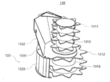
도 4를 다시 참조하고 도 5 내지 도 10을 참조하면, 운반부(131)는 지면에 예각인 제2 회전축(도 4의 A2)을 중심으로 회전하는 운반 블레이드(1311, 1312)를 포함할 수 있다.
운반 블레이드(1311, 1312)는 제1 운반 블레이드(1311) 및 제2 운반 블레이드(1312)를 포함할 수 있다.
제1 운반 블레이드(1311) 및 제2 운반 블레이드(1312)는 제2 회전축(도 4의 A2)을 중심으로 회전하여 절단부(121)에서 절단된 작물을 다시 절단하는 동시에 작물을 이동시킬 수 있다. 제1 운반 블레이드(1311) 및 제2 운반 블레이드(1312)는 복수의 톱니를 포함할 수 있다. 예를 들어, 제1 운반 블레이드(1311)의 톱니 간격이 제2 운반 블레이드(1312)의 톱니 간격보다 좁게 형성될 수 있다. 다른 예를 들어, 제1 운반 블레이드(1311)의 크기(지름)가 제2 운반 블레이드(1312)의 크기(지름)보다 작게 형성될 수 있다.
운반부(131)는 제1 운반 회전 드럼(1313) 및 제2 운반 회전 드럼(1314)을 더 포함할 수 있다.
제1 운반 회전 드럼(1313)에는 제1 운반 블레이드(1311)가 일정 간격을 두고 결합될 수 있다. 제1 운반 회전 드럼(1313)은 복수로 구성되어 제1 운반 블레이드(1311)와 1:1로 대응하여 설치되거나, 하나로 구성되어 복수의 제1 운반 블레이드(1311)가 일정 간격을 두고 설치될 수 있다. 제1 운반 회전 드럼(1313)의 중심에는 제2 회전축(A2)이 위치할 수 있다. 예를 들어, 제1 운반 회전 드럼(1313)은 원통형으로 형성될 수 있다.
제2 운반 회전 드럼(1314)에는 제2 운반 블레이드(1312)가 일정 간격을 두고 결합될 수 있다. 제2 운반 회전 드럼(1314)은 복수로 구성되어 제2 운반 블레이드(1312)와 1:1로 대응하여 설치되거나, 하나로 구성되어 복수의 제2 운반 블레이드(1312)가 일정 간격을 두고 설치될 수 있다. 제2 운반 회전 드럼(1314)의 중심에는 제2 회전축(A2)이 위치할 수 있다. 예를 들어, 제2 운반 회전 드럼(1314)은 원통형으로 형성될 수 있다.
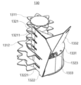
한 쌍의 인입 폭 조절부(132)는 운반부(131)에 서로 마주보게 설치될 수 있다. 한 쌍의 인입 폭 조절부(132)는 수동 또는 자동으로 동작하여 작물이 인입되는 공간의 폭을 조절할 수 있다.
한 쌍의 인입 폭 조절부(132)는 인입 고정 플레이트(1321), 인입 이동 플레이트(1322), 인입 폭 조절 부재(1323) 및 편 연결 부재(1324)를 포함할 수 있다.
인입 고정 플레이트(1321)는 운반부(131)에 결합되고 제1 슬릿 홀(13211)을 포함할 수 있다. 제1 슬릿 홀(13211)은 일정 간격으로 형성되고, 제1 운반 블레이드(1311) 및 제2 운반 블레이드(1312)가 회전하면서 통과할 수 있다.
인입 고정 플레이트(1321)의 상단은 운반 포집부(133)의 제1 포집 플레이트(1332)와 연결될 수 있다. 인입 고정 플레이트(1321)는 제1 포집 플레이트(1332)와 연결됨으로써 제1 운반 블레이드(1311)와 제1 운반 회전 드럼(1313)의 후면을 일부 감쌀 수 있다.
또한, 인입 고정 플레이트(1321)의 하단은 운반 포집부(133)의 제2 포집 플레이트(1333)와 연결될 수 있다. 인입 고정 플레이트(1321)는 제2 포집 플레이트(1333)와 연결됨으로써 제2 운반 블레이드(1312)와 제2 운반 회전 드럼(1314)의 후면을 일부 감쌀 수 있다.
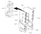
도 9 및 도 10에 도시된 바와 같이, 인입 고정 플레이트(1321)는 한 쌍의 플레이트 연결편(13212) 및 편 삽입홀(13213)을 더 포함할 수 있다.
한 쌍의 플레이트 연결편(13212)은 운반부(131) 방향으로 돌출 형성될 수 있다. 한 쌍의 플레이트 연결편(13212) 사이에는 편 삽입홀(13213)이 형성될 수 있다.
한 쌍의 플레이트 연결편(13212)은 편 연결부재(1324)를 통해 편 삽입홀(13213)로 삽입되는 플레이트 회전편(13222)과 연결될 수 있다. 여기서, 한 쌍의 플레이트 연결편(13212)는 편 연결부재(1324)가 끼움 결합되기 위한 제1 관통홀(132121)을 포함할 수 있다.
편 삽입홀(13213)은 한 쌍의 플레이트 연결편(13212) 사이에 형성될 수 있다. 편 삽입홀(13213)에는 플레이트 회전편(13222)이 삽입될 수 있다.
인입 고정 플레이트(1321)는 한 쌍의 플레이트 연결편(13212)을 통해 인입 이동 플레이트(1322)와 연결될 수 있다.
인입 이동 플레이트(1322)는 인입 고정 플레이트(1321)에 연결되고 제2 슬릿 홀(13221)을 포함할 수 있다. 제2 슬릿 홀(13221)은 제1 슬릿 홀(13211)에 대응하도록 일정 간격으로 형성되고, 제1 운반 블레이드(1311) 및 제2 운반 블레이드(1312)가 회전하면서 통과할 수 있다.
인입 이동 플레이트(1322)는 인입 고정 플레이트(1321)에 연결되고, 인입 폭 조절 부재(1323)에 의해 푸시되어 작물이 인입되는 폭을 조절할 수 있다.
여기서, 인입 이동 플레이트(1322)는 인입 폭 조절 부재(1323)에 의해 인입 고정 플레이트(1321)로부터 가까워지거나 멀어지도록 푸시되어 작물이 인입되는 폭을 조절할 수 있다(도 5의 (a) 및 (b) 참조).
도 9 및 도 10에 도시된 바와 같이, 인입 이동 플레이트(1322)는 플레이트 회전편(13222)을 더 포함할 수 있다.
플레이트 회전편(13222)은 운반부(131) 방향으로 돌출 형성될 수 있다. 플레이트 회전편(13222)은 인입 고정 플레이트(1321)의 편 삽입홀(13213)에 삽입되어 한 쌍의 플레이트 연결편(13212) 사이에 위치할 수 있다.
플레이트 회전편(13222)은 편 삽입홀(13213)에 삽입된 후 편 연결부재(1324)를 통해 한 쌍의 플레이트 연결편(13212)과 연결될 수 있다. 여기서, 플레이트 회전편(13222)에는 편 연결부재(1324)가 끼움 결합되기 위한 제2 관통홀(132221)을 포함할 수 있다.
인입 이동 플레이트(1322)는 인입 폭 조절 부재(1323)에 의해 푸시되면 한 쌍의 플레이트 연결편(13212)으로부터 플레이트 회전편(13222)이 회전하여 작물이 인입되는 폭을 조절할 수 있다.
인입 폭 조절 부재(1323)는 일단이 운반부(131)에 결합되고 타단이 인입 이동 플레이트(1322)에 연결되어 인입 이동 플레이트(1322)를 푸시할 수 있다. 인입 폭 조절 부재(1323)는 고정부(13231), 이동부(13232) 및 푸시부(13233)를 포함할 수 있다.
고정부(13231)는 운반부(131)에 결합될 수 있다. 보다 상세하게, 고정부(13231)는 운반 포집부(133)의 분리 플레이트(1331)에 결합될 수 있다.
이동부(13232)는 인입 이동 플레이트(1322)에 결합될 수 있다. 이동부(13232)는 고정부(13231)와 사이에 설치되는 푸시부(13233)에 의해 인입 이동 플레이트(1322)를 푸시할 수 있다.
푸시부(13233)는 고정부(13231)와 이동부(13232) 사이에 설치될 수 있다. 푸시부(13233)는 수동 또는 자동으로 구동될 수 있다.
한편, 본 실시예에서 인입 폭 조절 부재(1323)는 도면을 참조하여 고정부(13231), 이동부(13232) 및 푸시부(13233)로 구성되는 것으로 설명하였으나, 이에 한정하고자 하는 것은 아니며, 수동 방식 또는 자동 방식에 따라 유압 실린더, 리니어 모터, 스프링 등 다양한 구성으로도 채택할 수 있다.
편 연결부재(1324)는 한 쌍의 플레이트 연결편(13212)과 플레이트 회전편(13222)을 연결할 수 있다.
편 연결부재(1324)는 한 쌍의 플레이트 연결편(13212)의 제1 관통홀(132121)과 플레이트 회전편(13222)의 제1 관통홀(132221)에 삽입되어 한 쌍의 플레이트 연결편(13212)으로부터 플레이트 회전편(13222)이 회전 가능하도록 연결할 수 있다.
운반 포집부(133)는 운반부(131)의 후면으로 이동하는 작물이 트랙터용 작물 수확 장치(100)의 외측으로 이탈하지 않도록 운반부(131)를 감쌀 수 있다.
운반 포집부(133)는 분리 플레이트(1331), 제1 포집 플레이트(1332) 및 제2 포집 플레이트(1333)를 포함할 수 있다.
분리 플레이트(1331)는 제1 운반 회전 드럼(1313)과 제2 운반 회전 드럼(1314) 사이에 설치될 수 있다. 분리 플레이트(1331)는 제2 회전축(A2)에 수직인 면을 가지도록 형성될 수 있다.
분리 플레이트(1331)의 상부에는 제1 포집 플레이트(1332)가 연결되고, 분리 플레이트(1331)의 하부에는 제2 포집 플레이트(1333)가 연결될 수 있다.
제1 포집 플레이트(1332)는 분리 플레이트(1331)의 상부에 설치되어 인입 고정 플레이트(1321)와 연결될 수 있다. 제1 포집 플레이트(1332)는 인입 고정 플레이트(1321)와 함께 운반부(131)의 제1 운반 회전 드럼(1313)을 감쌀 수 있다.
제1 포집 플레이트(1332)는 제1 운반 회전 드럼(1313)을 감쌈으로써 운반부(131)의 후면으로 이동하는 작물이 이탈되지 않도록 할 수 있다.
제2 포집 플레이트(1333)는 분리 플레이트(1331)의 하부에 설치되어 인입 고정 플레이트(1321)와 연결될 수 있다. 제2 포집 플레이트(1333)는 인입 고정 플레이트(1321)와 함께 운반부(131)의 제2 운반 회전 드럼(1314)을 감쌀 수 있다.
제2 포집 플레이트(1333)는 제2 운반 회전 드럼(1314)을 감쌈으로써 운반부(131)의 후면으로 이동하는 작물이 이탈되지 않도록 할 수 있다.
도 11은 본 발명의 실시예에 따른 트랙터용 작물 수확 장치의 롤러 모듈을 도시한 사시도이다.
도 11을 참조하면, 롤러 모듈(140)은 제1 결합부(111)에 결합되고 한 쌍의 인입 폭 조절부(132) 사이에 배치되어 운반부(131)로 유입되는 작물을 높이 방향으로 눌러줄 수 있다. 롤러 모듈(140)은 롤러 고정부(141) 및 롤러부(142)를 포함할 수 있다.
롤러 고정부(141)는 일단 및 타단이 제2 결합부(112)를 중심으로 제1 결합부(111)에 각각 결합될 수 있다. 롤러 고정부(141)는 롤러부(142)와 결합되어 롤러부(142)를 한 쌍의 인입 폭 조절부(132)의 일정 위치에 고정시킬 수 있다. 롤러 고정부(141)는 제1 롤러 고정 플레이트(1411), 롤러 고정 연장 플레이트(1412) 및 제2 롤러 고정 플레이트(1413)를 포함할 수 있다.
제1 롤러 고정 플레이트(1411)는 제1 결합부(111)에 결합될 수 있다. 제1 롤러 고정 플레이트(1411)에는 롤러 고정 연장 플레이트(1412)가 연장될 수 있다.
롤러 고정 연장 플레이트(1412)는 제1 롤러 고정 플레이트(1411)에서 연장될 수 있다. 롤러 고정 연장 플레이트(1412)는 ㄷ자로 형성될 수 있으나, 이에 한정하고자 하는 것은 아니며 롤러부(142)를 일정 높이에 위치시킬 수 있는 구조라면 어떠한 형태도 채택 가능하다.
제2 롤러 고정 플레이트(1413)는 롤러 고정 연장 플레이트(1412)에서 연장되고 제1 결합부(111)에 결합될 수 있다.
일 실시예에서, 제1 롤러 고정 플레이트(1411)와 제2 롤러 고정 플레이트(1413)는 제1 결합부(111)에 탈부착 가능하도록 설치될 수 있다. 예를 들어, 제1 결합부(111)가 자성을 가지는 소재로 형성되는 경우 제1 롤러 고정 플레이트(1411)와 제2 롤러 고정 플레이트(1413)는 자성을 가지는 소재로 형성되어 제1 결합부(111)에 탈부착될 수 있다.
롤러부(142)는 롤러 고정부(141)에 연결되어 한 쌍의 인입 폭 조절부(132) 사이에 배치될 수 있다. 롤러부(142)는 한 쌍의 인입 폭 조절부(132) 사이에서 높이가 조절되어 한 쌍의 인입 폭 조절부(132) 사이로 유입되는 작물을 눌러줄 수 있다. 롤러부(142)는 한 쌍의 높이 조절부재(1421), 한 쌍의 롤러 회전부재(1422) 및 롤러부재(1423)를 포함할 수 있다.
한 쌍의 높이 조절부재(1421)는 일단이 롤러 고정 연장 플레이트(1412)의 제1면에 연결되고 타단이 한 쌍의 롤러 회전부재(1422)의 타단에 각각 연결될 수 있다. 한 쌍의 높이 조절부재(1421)는 길이 조절 가능하게 형성되고, 길이 조절에 따라 한 쌍의 롤러 회전부재(1422)를 밀거나 당길 수 있다. 예를 들어, 한 쌍의 높이 조절부재(1421)는 가스 스프링, 압축 스프링 등 일 수 있다.
한 쌍의 롤러 회전부재(1422)는 일단이 롤러 고정 연장 플레이트(1412)의 제2면에 연결되고 타단이 한 쌍의 높이 조절부재(1421)의 타단 각각에 연결될 수 있다. 여기서 제2면은 제1면과 이웃하는 면일 수 있다.
한 쌍의 롤러 회전부재(1422)는 한 쌍의 높이 조절부재(1421)의 길이 조절에 따라 롤러 고정 연장 플레이트(1412)로부터 회전할 수 있다. 즉, 한 쌍의 롤러 회전부재(1422)의 일단은 롤러 고정 연장 플레이트(1412)로부터 회전 가능하게 연결되고, 한 쌍의 롤러 회전부재(1422)의 타단은 한 쌍의 높이 조절부재(1421)로부터 회전 가능하게 연결될 수 있다. 이러한 연결 상태에서 한 쌍의 롤러 회전부재(1422)는 한 쌍의 높이 조절부재(1421)의 길이 조절에 따라 높이 방향으로 밀리거나 당겨지면 롤러 고정 연장 플레이트(1412)로부터 회전하여 롤러부재(1423)의 높이를 조절할 수 있다.
이때 한 쌍의 롤러 회전부재(1422)는 일단과 타단 사이에 절곡부(14221)를 포함하고, 절곡부(14221)에서 롤러부재(1423)가 축 연결될 수 있다.
롤러부재(1423)는 한 쌍의 롤러 회전부재(1422) 사이에 배치되어 한 쌍의 롤러 회전부재(1422) 각각의 일단과 타단 사이에 축 연결될 수 있다. 즉, 롤러부재(1423)는 한 쌍의 롤러 회전부재(1422)의 절곡부(14221)에 회전 가능하도록 연결될 수 있다.
롤러부재(1423)는 한 쌍의 높이 조절부재(1421)에 의해 한 쌍의 롤러 회전부재(1422)가 높이 방향으로 이동하면 높이가 조절될 수 있다. 여기서 롤러부재(1423)는 한 쌍의 인입 폭 조절부(132)의 사이에 배치되고, 한 쌍의 인입 폭 조절부(132)의 사이에서 높이가 조절되어 한 쌍의 인입 폭 조절부(132) 사이로 유입되는 작물을 눌러줄 수 있다.
이때 롤러부재(1423)는 한 쌍의 롤러 회전부재(1422)의 절곡부(14221)에 회전 가능하게 축 연결되므로 작물이 유입될 때 회전하면서 트랙터 내부의 작물 저장 공간(미도시됨)으로 작물을 밀어줄 수 있다.
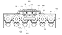
도 12 및 도 13은 본 발명의 실시예에 따른 트랙터용 작물 수확 장치를 이용한 작물의 흐름 및 인입 폭 조절부의 동작을 설명하기 위한 평면도이다.
도 12 및 도 13을 참조하여 작물의 이동 방향을 설명하면, 작물은 트랙터(미도시됨)의 이동에 따라 가이드부(122)에 의해 가이드되면 절단부(121)에 의해 절단될 수 있다(P1).
작물은 절단부(121)의 회전 방향에 따라 회전하면서 절단부(121)의 후단으로 이동할 수 있다(P2). 여기서 절단부(121)의 회전 방향은 도면에 도시된 바와 같이 각 절단부(121)마다 상이할 수 있으며, 도면에 도시된 방향은 작물을 최대한 운반 모듈(130)로 포집하기 위한 것으로, 이에 한정하고자 하는 것은 아니다.
작물은 절단부(121)의 후단으로 이동한 후 절단부(121)의 후단 중심으로 포집되어 운반 모듈(130)로 이동할 수 있다(P3). 이때 작물의 양, 크기 등에 따라 운반 모듈(130)의 인입 폭 조절부(132)가 폭 조절되고, 롤러 모듈(140)의 롤러부(142)가 높이 조절될 수 있다.
상기에서는 본 발명의 일 실시예를 참조하여 설명하였지만, 해당 기술 분야에서 통상의 지식을 가진 자라면 하기의 특허 청구의 범위에 기재된 본 발명의 사상 및 영역으로부터 벗어나지 않는 범위 내에서 본 발명을 다양하게 수정 및 변경시킬 수 있음을 이해할 수 있을 것이다.
Claims (6)
- 트랙터의 전단에 결합되고, 제1 결합부 및 제2 결합부를 포함하는 절단 프레임;상기 제1 결합부에 설치되고, 지면에 수직인 제1 회전축을 중심으로 회전하는 절단 블레이드를 포함하는 절단부 및 전방으로 돌출되도록 상기 절단부에 결합되는 가이드부를 포함하는 절단 모듈;상기 제2 결합부에 설치되고, 지면에 예각인 제2 회전축을 중심으로 회전하는 운반 블레이드를 포함하는 운반부 및 상기 운반부에 서로 마주보게 설치되는 한 쌍의 인입 폭 조절부를 포함하는 운반 모듈; 및일단 및 타단이 상기 제2 결합부를 중심으로 상기 제1 결합부에 각각 결합되는 롤러 고정부 및 상기 롤러 고정부에 연결되어 상기 한 쌍의 인입 폭 조절부 사이에 배치되는 롤러부를 포함하는 롤러 모듈을 포함하는 트랙터용 작물 수확 장치.
- 제1항에 있어서,상기 롤러 고정부는,상기 제1 결합부에 결합되는 제1 롤러 고정 플레이트, 상기 제1 롤러 고정 플레이트에서 연장되는 롤러 고정 연장 플레이트 및 상기 롤러 고정 연장 플레이트에서 연장되고 상기 제1 결합부에 결합되는 제2 롤러 고정 플레이트를 포함하는 트랙터용 작물 수확 장치.
- 제2항에 있어서,상기 롤러부는,일단이 상기 롤러 고정 연장 플레이트의 제1면에 연결되는 한 쌍의 높이 조절부재, 일단이 상기 롤러 고정 연장 플레이트의 제2면에 연결되고 타단이 상기 한 쌍의 높이 조절부재의 타단 각각에 연결되는 한 쌍의 롤러 회전부재 및 상기 한 쌍의 롤러 회전부재 사이에 배치되어 상기 한 쌍의 롤러 회전부재 각각의 일단과 타단 사이에 축 연결되는 롤러부재를 포함하는 트랙터용 작물 수확 장치.
- 제1항에 있어서,상기 인입 폭 조절부는,상기 운반부에 결합되고 제1 슬릿 홀을 포함하는 인입 고정 플레이트, 상기 인입 고정 플레이트에 연결되고 제2 슬릿 홀을 포함하는 인입 이동 플레이트 및 일단이 상기 운반부에 결합되고 타단이 상기 인입 이동 플레이트에 연결되어 상기 인입 이동 플레이트를 푸시하는 인입 폭 조절 부재를 포함하는 트랙터용 작물 수확 장치.
- 제4항에 있어서,상기 인입 고정 플레이트는 상기 운반부 방향으로 돌출된 한 쌍의 플레이트 연결편 및 상기 한 쌍의 플레이트 연결편 사이에 형성된 편 삽입홀을 더 포함하고,상기 인입 이동 플레이트는 상기 운반부 방향으로 돌출되고 상기 편 삽입홀에 삽입되는 플레이트 회전편을 더 포함하며,상기 인입 폭 조절부는,상기 한 쌍의 플레이트 연결편과 상기 플레이트 회전편을 연결하는 편 연결부재를 더 포함하는 트랙터용 작물 수확 장치.
- 제1항에 있어서,상기 운반 블레이드는 제1 운반 블레이드 및 제2 운반 블레이드를 포함하고,상기 운반부는,상기 제1 운반 블레이드가 결합된 제1 운반 회전 드럼 및 상기 제1 운반 회전 드럼의 하부에 결합되고 상기 제2 운반 블레이드가 결합된 제2 운반 회전 드럼을 더 포함하는 트랙터용 작물 수확 장치.
Applications Claiming Priority (2)
| Application Number | Priority Date | Filing Date | Title |
|---|---|---|---|
| KR10-2023-0075848 | 2023-06-13 | ||
| KR1020230075848A KR20240175638A (ko) | 2023-06-13 | 2023-06-13 | 트랙터용 작물 수확 장치 |
Publications (1)
| Publication Number | Publication Date |
|---|---|
| WO2024257975A1 true WO2024257975A1 (ko) | 2024-12-19 |
Family
ID=93852059
Family Applications (1)
| Application Number | Title | Priority Date | Filing Date |
|---|---|---|---|
| PCT/KR2023/020326 Ceased WO2024257975A1 (ko) | 2023-06-13 | 2023-12-11 | 트랙터용 작물 수확 장치 |
Country Status (2)
| Country | Link |
|---|---|
| KR (1) | KR20240175638A (ko) |
| WO (1) | WO2024257975A1 (ko) |
Citations (5)
| Publication number | Priority date | Publication date | Assignee | Title |
|---|---|---|---|---|
| JPH0767435A (ja) * | 1993-09-01 | 1995-03-14 | Bunmei Noki Kk | 葉タバコ収穫機 |
| KR200466126Y1 (ko) * | 2012-06-29 | 2013-04-03 | 박정규 | 예취기용 디스크장치 |
| KR101623846B1 (ko) * | 2016-03-16 | 2016-06-07 | 박정규 | 농업용 다기능 예취기 |
| JP2017006078A (ja) * | 2015-06-24 | 2017-01-12 | 井関農機株式会社 | 作物引抜機 |
| KR101712128B1 (ko) * | 2014-12-05 | 2017-03-06 | 오페주식회사 | 콤바인용 예취장치 |
Family Cites Families (1)
| Publication number | Priority date | Publication date | Assignee | Title |
|---|---|---|---|---|
| KR101282927B1 (ko) | 2012-07-04 | 2013-07-08 | 남미정 | 트랙터용 전방형 농산물수확기 |
-
2023
- 2023-06-13 KR KR1020230075848A patent/KR20240175638A/ko not_active Ceased
- 2023-12-11 WO PCT/KR2023/020326 patent/WO2024257975A1/ko not_active Ceased
Patent Citations (5)
| Publication number | Priority date | Publication date | Assignee | Title |
|---|---|---|---|---|
| JPH0767435A (ja) * | 1993-09-01 | 1995-03-14 | Bunmei Noki Kk | 葉タバコ収穫機 |
| KR200466126Y1 (ko) * | 2012-06-29 | 2013-04-03 | 박정규 | 예취기용 디스크장치 |
| KR101712128B1 (ko) * | 2014-12-05 | 2017-03-06 | 오페주식회사 | 콤바인용 예취장치 |
| JP2017006078A (ja) * | 2015-06-24 | 2017-01-12 | 井関農機株式会社 | 作物引抜機 |
| KR101623846B1 (ko) * | 2016-03-16 | 2016-06-07 | 박정규 | 농업용 다기능 예취기 |
Also Published As
| Publication number | Publication date |
|---|---|
| KR20240175638A (ko) | 2024-12-20 |
Similar Documents
| Publication | Publication Date | Title |
|---|---|---|
| WO2024257975A1 (ko) | 트랙터용 작물 수확 장치 | |
| WO2021054795A1 (ko) | 자동탈봉장치 | |
| CN115568341A (zh) | 摇轴组件以及圆形捆或模块构建机器和系统 | |
| WO2015068996A1 (ko) | 수액제거부재, 수액 채취장치용 컷팅부 및 이를 포함하는 수액 채취장치 | |
| WO2024122706A1 (ko) | 트랙터용 작물 수확 장치 | |
| WO2017204444A2 (ko) | 베일러의 로터 장치 | |
| CA2038783A1 (en) | Crop harvesting apparatus | |
| US6408605B1 (en) | Cotton harvester row unit | |
| US5595052A (en) | Bat for a reel having an anti-wrap extension | |
| US5884464A (en) | Narrow row corn head with staggered height row units | |
| SE511557C2 (sv) | Applikator för löstagbar montering i en anslutningskrimpningsmaskin | |
| WO2013162155A1 (ko) | 콤바인용 작물 이송장치 | |
| RS55008B1 (sr) | Adapter kombajna za berbu zrnastih useva, naročito kukuruza | |
| CN119213912A (zh) | 一种均匀撒布秸秆粉末的秸秆粉碎还田机 | |
| EP0846409B1 (en) | Modular stalkroll with a three bolt attachment means | |
| CN112772126A (zh) | 一种间距可调式玉米梳脱摘穗割台 | |
| WO2012033391A2 (ko) | 다목적 작물 수확기 | |
| DE69207152T2 (de) | Apparat zum Herausziehen eines Bahnendes einer Bandwickelrolle | |
| JP3499422B2 (ja) | 普通形コンバイン | |
| WO2011059214A2 (ko) | 오징어 가공기 | |
| WO2012077937A2 (ko) | 종자 파종기 | |
| WO2025105842A1 (ko) | 트랙터용 모어 모듈 | |
| WO2020251161A1 (ko) | 예취기용 감김방지 장치 및 이를 채용하는 예취기 | |
| JPH01317316A (ja) | テープ苗の分離装置 | |
| CN223694373U (zh) | 一种玉米收获机割台试验台夹持输送装置 |
Legal Events
| Date | Code | Title | Description |
|---|---|---|---|
| 121 | Ep: the epo has been informed by wipo that ep was designated in this application |
Ref document number: 23941756 Country of ref document: EP Kind code of ref document: A1 |
|
| NENP | Non-entry into the national phase |
Ref country code: DE |