WO2024257975A1 - Appareil de récolte de cultures pour tracteur - Google Patents
Appareil de récolte de cultures pour tracteur Download PDFInfo
- Publication number
- WO2024257975A1 WO2024257975A1 PCT/KR2023/020326 KR2023020326W WO2024257975A1 WO 2024257975 A1 WO2024257975 A1 WO 2024257975A1 KR 2023020326 W KR2023020326 W KR 2023020326W WO 2024257975 A1 WO2024257975 A1 WO 2024257975A1
- Authority
- WO
- WIPO (PCT)
- Prior art keywords
- transport
- plate
- roller
- pair
- inlet
- Prior art date
- Legal status (The legal status is an assumption and is not a legal conclusion. Google has not performed a legal analysis and makes no representation as to the accuracy of the status listed.)
- Ceased
Links
Images


Classifications
-
- A—HUMAN NECESSITIES
- A01—AGRICULTURE; FORESTRY; ANIMAL HUSBANDRY; HUNTING; TRAPPING; FISHING
- A01D—HARVESTING; MOWING
- A01D43/00—Mowers combined with apparatus performing additional operations while mowing
- A01D43/06—Mowers combined with apparatus performing additional operations while mowing with means for collecting, gathering or loading mown material
- A01D43/077—Mowers combined with apparatus performing additional operations while mowing with means for collecting, gathering or loading mown material with auxiliary means, e.g. fans, for transporting the mown crop
-
- A—HUMAN NECESSITIES
- A01—AGRICULTURE; FORESTRY; ANIMAL HUSBANDRY; HUNTING; TRAPPING; FISHING
- A01B—SOIL WORKING IN AGRICULTURE OR FORESTRY; PARTS, DETAILS, OR ACCESSORIES OF AGRICULTURAL MACHINES OR IMPLEMENTS, IN GENERAL
- A01B59/00—Devices specially adapted for connection between animals or tractors and agricultural machines or implements
- A01B59/06—Devices specially adapted for connection between animals or tractors and agricultural machines or implements for machines mounted on tractors
- A01B59/064—Devices specially adapted for connection between animals or tractors and agricultural machines or implements for machines mounted on tractors for connection to the front of the tractor
-
- A—HUMAN NECESSITIES
- A01—AGRICULTURE; FORESTRY; ANIMAL HUSBANDRY; HUNTING; TRAPPING; FISHING
- A01D—HARVESTING; MOWING
- A01D33/00—Accessories for digging harvesters
- A01D33/10—Crop collecting devices, with or without weighing apparatus
-
- A—HUMAN NECESSITIES
- A01—AGRICULTURE; FORESTRY; ANIMAL HUSBANDRY; HUNTING; TRAPPING; FISHING
- A01D—HARVESTING; MOWING
- A01D34/00—Mowers; Mowing apparatus of harvesters
- A01D34/01—Mowers; Mowing apparatus of harvesters characterised by features relating to the type of cutting apparatus
- A01D34/412—Mowers; Mowing apparatus of harvesters characterised by features relating to the type of cutting apparatus having rotating cutters
- A01D34/63—Mowers; Mowing apparatus of harvesters characterised by features relating to the type of cutting apparatus having rotating cutters having cutters rotating about a vertical axis
- A01D34/64—Mowers; Mowing apparatus of harvesters characterised by features relating to the type of cutting apparatus having rotating cutters having cutters rotating about a vertical axis mounted on a vehicle, e.g. a tractor, or drawn by an animal or a vehicle
- A01D34/66—Mowers; Mowing apparatus of harvesters characterised by features relating to the type of cutting apparatus having rotating cutters having cutters rotating about a vertical axis mounted on a vehicle, e.g. a tractor, or drawn by an animal or a vehicle with two or more cutters
Definitions
- the present invention relates to a crop harvesting device for a tractor, and more specifically, to a crop harvesting device for a tractor which can improve crop introduction performance by minimizing stagnation and clogging of crops by adjusting the width and height of an introduction portion when cutting crops and introducing the cut crops into a treatment tank.
- auxiliary agricultural tools such as detachable agricultural harvesters
- power-driven agricultural machines such as cultivators and tractors
- These agricultural harvesters can save labor when harvesting crops, and can harvest grains, vegetables, and fruits, depending on the type.
- Conventional agricultural harvesters can harvest a variety of crops including corn, sudan grass, and ryegrass, but they have the problem of crops frequently becoming clogged due to the fixed width of the inlet without considering the size, thickness, and properties of the crops.
- Patent Document 1 Korean Patent No. 10-1282927 (registered on July 1, 2013)
- the present invention has been made to solve the above-described problems, and the purpose of the present invention is to provide a crop harvesting device for a tractor capable of improving crop introduction performance by minimizing stagnation and clogging of crops by adjusting the width and height of an introduction portion when cutting crops and introducing the cut crops into a treatment tank.
- a crop harvesting device for a tractor may include a cutting frame coupled to a front end of the tractor and including a first coupling portion and a second coupling portion, a cutting portion installed at the first coupling portion and including a cutting blade that rotates around a first rotation axis that is perpendicular to the ground, and a cutting module that includes a guide portion coupled to the cutting portion so as to protrude forward, a transport portion installed at the second coupling portion and including a transport blade that rotates around a second rotation axis that is acute to the ground, and a transport module including a pair of inlet width adjusting portions that are installed to face each other on the transport portion, and a roller module including a roller fixing portion, one end and the other end of which are respectively coupled to the first coupling portion centered on the second coupling portion, and a roller portion that is connected to the roller fixing portion and is disposed between the pair of inlet width adjusting portions.
- the roller fixing member may include a first roller fixing plate coupled to the first coupling member, a roller fixing extension plate extending from the first roller fixing plate, and a second roller fixing plate extending from the roller fixing extension plate and coupled to the first coupling member.
- the roller section may include a pair of height-adjusting members, one end of which is connected to a first surface of the roller-fixing extension plate, a pair of roller rotation members, one end of which is connected to a second surface of the roller-fixing extension plate and the other end of which is connected to each of the other ends of the pair of height-adjusting members, and a roller member disposed between the pair of roller rotation members and axially connected between each end and the other end of the pair of roller rotation members.
- the inlet width adjustment unit may include an inlet fixed plate coupled to the transport unit and including a first slit hole, an inlet movable plate coupled to the inlet fixed plate and including a second slit hole, and an inlet width adjustment member having one end coupled to the transport unit and the other end connected to the inlet movable plate to push the inlet movable plate.
- the inlet fixed plate may further include a pair of plate connecting pieces protruding in the direction of the transport section and a side insertion hole formed between the pair of plate connecting pieces
- the inlet movable plate may further include a plate rotating piece protruding in the direction of the transport section and inserted into the side insertion hole
- the inlet width adjusting section may further include a side connecting member connecting the pair of plate connecting pieces and the plate rotating piece.
- the transport blade may include a first transport blade and a second transport blade
- the transport section may further include a first transport rotary drum to which the first transport blade is coupled and a second transport rotary drum coupled to a lower portion of the first transport rotary drum and to which the second transport blade is coupled.
- a crop harvesting device for a tractor provides the following effects.
- the present invention has the effect of improving crop introduction performance by minimizing stagnation and clogging of crops by adjusting the width and height of the introduction portion when cutting crops and introducing the cut crops into a treatment tank.
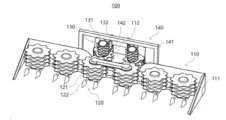
- FIG. 1 is a perspective view illustrating a crop harvesting device for a tractor according to an embodiment of the present invention.
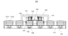
- FIG. 2 is a front view illustrating a crop harvesting device for a tractor according to an embodiment of the present invention.
- FIG. 3 is a rear view illustrating a crop harvesting device for a tractor according to an embodiment of the present invention.
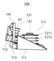
- FIG. 4 is a side view illustrating a crop harvesting device for a tractor according to an embodiment of the present invention.
- Figures 5 to 7 are perspective views illustrating a transport module of a crop harvesting device for a tractor according to an embodiment of the present invention.
- FIG. 8 is a partially exploded perspective view illustrating a transport module of a crop harvesting device for a tractor according to an embodiment of the present invention.
- FIG. 9 is a perspective view for explaining an introduction fixing plate and an introduction moving plate of an introduction width adjusting unit of a crop harvesting device for a tractor according to an embodiment of the present invention.
- FIG. 10 is an exploded perspective view illustrating an introduction fixing plate and an introduction moving plate of an introduction width adjusting unit of a crop harvesting device for a tractor according to an embodiment of the present invention.
- FIG. 11 is a perspective view illustrating a roller module of a crop harvesting device for a tractor according to an embodiment of the present invention.
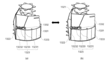
- FIGS. 12 and 13 are plan views for explaining the operation of a crop flow and inlet width control unit using a crop harvesting device for a tractor according to an embodiment of the present invention.
- first, second, etc. may be used to describe various components, but the components should not be limited by the terms. The terms are used only to distinguish one component from another.
- FIGS. 1 to 13 a crop harvesting device for a tractor according to embodiments of the present invention will be described in detail with reference to FIGS. 1 to 13.
- FIG. 1 is a perspective view illustrating a crop harvesting device for a tractor according to an embodiment of the present invention
- FIG. 2 is a front view illustrating a crop harvesting device for a tractor according to an embodiment of the present invention
- FIG. 3 is a rear view illustrating a crop harvesting device for a tractor according to an embodiment of the present invention
- FIG. 4 is a side view illustrating a crop harvesting device for a tractor according to an embodiment of the present invention.
- a crop harvesting device (100) for a tractor can be attached to a tractor (not shown) and used to harvest crops.
- the crop harvesting device (100) for a tractor can include a cutting frame (110), a cutting module (120), a transport module (130), and a roller module (140).
- the cutting frame (110) can be coupled to the front end of the tractor.
- the cutting frame (110) can include a first coupling portion (111), a second coupling portion (112), and a third coupling portion (113).
- the first connecting portion (111) may have a T-shaped structure when viewed from a plane, and a triangular structure when viewed from the side.
- a cutting portion (121) and a guide portion (122) of a cutting module (120) may be installed on one part of the first connecting portion (111), that is, the front end.
- a second connecting portion (112) may be coupled to another part of the first connecting portion (111), that is, the rear end.
- the second coupling part (112) can be coupled to the first coupling part (111) at another part of the first coupling part (111), that is, at a part adjacent to the tractor.
- a transport part (131) of a transport module (130) and a pair of inlet width adjusting parts (132) can be installed in the second coupling part (112).
- the third connecting part (113) can be connected to the lower surface of the second connecting part (112).
- the third connecting part (113) is a part to which the tractor is connected and can be formed in a form that can be attached and detached to the front end of the tractor.
- the cutting module (120) can be installed in the first connecting portion (111) of the shear frame (110).
- the cutting module (120) can cut the crop and guide the movement of the crop.
- the cutting module (120) can include a cutting portion (121) and a guide portion (122).
- the cutting unit (121) may include a cutting blade (1211) that rotates around a first rotation axis (A1 in FIG. 4) that is perpendicular to the ground and a cutting rotary drum (1212) to which the cutting blade (1211) is coupled.
- the cutting blade (1211) can rotate around the first rotation axis (A1 in FIG. 4) to cut the crop and simultaneously move the cut crop to the transport module (130).
- the cutting blade (1211) can include a plurality of teeth.
- a plurality of cutting blades (1211) can be connected to a cutting rotating drum (1212) at regular intervals.
- the cutting blade (1211) may include a first cutting blade having first teeth formed at a first interval, a second cutting blade having second teeth formed at a second interval narrower than the first interval, and a third cutting blade having third teeth formed at a third interval narrower than the second interval.
- the first cutting blade, the second cutting blade, and the third cutting blade may be sequentially coupled to the cutting rotary drum (1212).
- the cutting rotary drum (1212) may be configured in multiples and installed in a 1:1 correspondence with the cutting blade (1211), or may be configured in one and multiple cutting blades (1211) may be installed at a set interval.
- a first rotation axis (A1) may be located at the center of the cutting rotary drum (1212).
- the cutting rotary drum (1212) may be formed in a cylindrical shape.
- the guide part (122) can be combined with the cutting part (121).
- the guide part (122) is formed to protrude in the forward direction of the tractor and can guide the positional movement of the crop so that the crop can be smoothly drawn toward the cutting part (121).
- the guide member (122) may be formed to be adjustable in length and angle according to the length, thickness, etc. of the crop.
- the guide member (122) may be formed to be adjustable in length in the forward direction of the tractor in a telescopic manner.
- the guide member (122) may be formed to be adjustable in angle in a direction perpendicular to the forward direction of the tractor by including at least one joint.
- the transport module (130) can be installed in the second connecting portion (112) of the shear frame (110).
- the transport module (130) can re-cut the cut crop and simultaneously move the crop to a crop storage space (not shown) inside the tractor.
- the transport module (130) can include a transport section (131), a pair of inlet width adjustment sections (132), and a transport catch section (133).
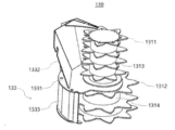
- FIGS. 5 to 7 are perspective views illustrating a transport module of a crop harvesting device for a tractor according to an embodiment of the present invention
- FIG. 8 is a partially exploded perspective view illustrating a transport module of a crop harvesting device for a tractor according to an embodiment of the present invention
- FIG. 9 is a perspective view illustrating an introduction fixing plate and an introduction moving plate of an introduction width adjusting unit of a crop harvesting device for a tractor according to an embodiment of the present invention
- FIG. 10 is an exploded perspective view illustrating an introduction fixing plate and an introduction moving plate of an introduction width adjusting unit of a crop harvesting device for a tractor according to an embodiment of the present invention.
- the transport unit (131) may include a transport blade (1311, 1312) that rotates about a second rotational axis (A2 in FIG. 4) that is at an acute angle to the ground.
- the transport blades (1311, 1312) may include a first transport blade (1311) and a second transport blade (1312).
- the first transport blade (1311) and the second transport blade (1312) can rotate around the second rotation axis (A2 of FIG. 4) to re-cut the crop cut at the cutting section (121) and simultaneously move the crop.
- the first transport blade (1311) and the second transport blade (1312) can include a plurality of teeth.
- the tooth spacing of the first transport blade (1311) can be formed narrower than the tooth spacing of the second transport blade (1312).
- the size (diameter) of the first transport blade (1311) can be formed smaller than the size (diameter) of the second transport blade (1312).
- the transport unit (131) may further include a first transport rotation drum (1313) and a second transport rotation drum (1314).
- the first transport rotary drum (1313) may be coupled with first transport blades (1311) at a predetermined interval.
- the first transport rotary drum (1313) may be configured in multiples and installed in a 1:1 correspondence with the first transport blades (1311), or may be configured in one and multiple first transport blades (1311) may be installed at a predetermined interval.
- a second rotation axis (A2) may be located at the center of the first transport rotary drum (1313).
- the first transport rotary drum (1313) may be formed in a cylindrical shape.
- the second transport rotary drum (1314) may be coupled with second transport blades (1312) at a predetermined interval.
- the second transport rotary drum (1314) may be configured in multiples and installed in a 1:1 correspondence with the second transport blades (1312), or may be configured in one and multiple second transport blades (1312) may be installed at a predetermined interval.
- a second rotation axis (A2) may be located at the center of the second transport rotary drum (1314).
- the second transport rotary drum (1314) may be formed in a cylindrical shape.
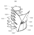
- a pair of inlet width adjusting parts (132) can be installed facing each other on the transport part (131).
- a pair of inlet width adjusting parts (132) can be operated manually or automatically to adjust the width of the space into which crops are introduced.
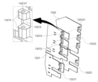
- a pair of inlet width adjusting members (132) may include an inlet fixing plate (1321), an inlet moving plate (1322), an inlet width adjusting member (1323), and a single connecting member (1324).
- the inlet fixing plate (1321) is coupled to the transport member (131) and may include a first slit hole (13211).
- the first slit hole (13211) is formed at a certain interval and the first transport blade (1311) and the second transport blade (1312) can pass through while rotating.
- the upper end of the inlet fixing plate (1321) can be connected to the first capturing plate (1332) of the transport capturing unit (133).
- the inlet fixing plate (1321) can partially wrap around the rear of the first transport blade (1311) and the first transport rotating drum (1313) by being connected to the first capturing plate (1332).
- the lower end of the inlet fixing plate (1321) can be connected to the second capturing plate (1333) of the transport capturing unit (133).
- the inlet fixing plate (1321) can partially wrap around the rear of the second transport blade (1312) and the second transport rotating drum (1314) by being connected to the second capturing plate (1333).
- the inlet fixing plate (1321) may further include a pair of plate connecting pieces (13212) and a piece insertion hole (13213).
- a pair of plate connecting pieces (13212) may be formed to protrude toward the transport section (131).
- a plate insertion hole (13213) may be formed between the pair of plate connecting pieces (13212).
- a pair of plate connecting pieces (13212) can be connected to a plate rotating piece (13222) inserted into a plate insertion hole (13213) through a plate connecting member (1324).
- the pair of plate connecting pieces (13212) can include a first through hole (132121) for the plate connecting member (1324) to be fitted.
- a plate insertion hole (13213) can be formed between a pair of plate connecting pieces (13212).
- a plate rotating piece (13222) can be inserted into the plate insertion hole (13213).
- the inlet fixing plate (1321) can be connected to the inlet moving plate (1322) through a pair of plate connecting pieces (13212).
- the inlet moving plate (1322) is connected to the inlet fixed plate (1321) and may include a second slit hole (13221).
- the second slit holes (13221) are formed at a predetermined interval to correspond to the first slit hole (13211), and the first transport blade (1311) and the second transport blade (1312) can pass through while rotating.
- the introduction moving plate (1322) is connected to the introduction fixed plate (1321) and is pushed by the introduction width adjusting member (1323) to adjust the width at which the crop is introduced.
- the inlet moving plate (1322) can be pushed closer to or further away from the inlet fixed plate (1321) by the inlet width adjusting member (1323) to adjust the width at which the crop is introduced (see (a) and (b) of FIG. 5).
- the inlet moving plate (1322) may further include a plate rotation piece (13222).
- the plate rotation piece (13222) can be formed to protrude in the direction of the transport part (131).
- the plate rotation piece (13222) can be inserted into the piece insertion hole (13213) of the inlet fixing plate (1321) and positioned between a pair of plate connecting pieces (13212).
- the plate rotating piece (13222) can be connected to a pair of plate connecting pieces (13212) through a connecting piece (1324) after being inserted into the insertion hole (13213).
- the plate rotating piece (13222) can include a second through hole (132221) for fitting and connecting the connecting piece (1324).
- the plate rotation member (13222) rotates from a pair of plate connecting members (13212) to adjust the width at which the crop is introduced.
- the introduction width adjustment member (1323) has one end connected to the transport member (131) and the other end connected to the introduction movement plate (1322) so as to push the introduction movement plate (1322).
- the introduction width adjustment member (1323) may include a fixed part (13231), a moving part (13232), and a pushing part (13233).
- the fixed part (13231) can be coupled to the transport part (131). More specifically, the fixed part (13231) can be coupled to the separation plate (1331) of the transport collecting part (133).
- the moving part (13232) can be coupled to the inlet moving plate (1322).
- the moving part (13232) can push the inlet moving plate (1322) by a push part (13233) installed between the fixed part (13231).
- the push unit (13233) can be installed between the fixed unit (13231) and the moving unit (13232).
- the push unit (13233) can be driven manually or automatically.
- the inlet width adjustment member (1323) is described as consisting of a fixed part (13231), a moving part (13232), and a push part (13233) with reference to the drawing, but is not limited thereto, and may be adopted in various configurations such as a hydraulic cylinder, a linear motor, and a spring depending on the manual or automatic method.
- a plate connecting member (1324) can connect a pair of plate connecting members (13212) and a plate rotating member (13222).
- the plate connecting member (1324) can be inserted into the first through hole (132121) of a pair of plate connecting pieces (13212) and the first through hole (132221) of the plate rotating piece (13222) so that the plate rotating piece (13222) can be rotatably connected to the pair of plate connecting pieces (13212).
- the transport catcher (133) can wrap around the transporter (131) to prevent crops moving to the rear of the transporter (131) from escaping to the outside of the crop harvesting device (100) for a tractor.
- the transport capture unit (133) may include a separation plate (1331), a first capture plate (1332), and a second capture plate (1333).
- a separating plate (1331) may be installed between the first transport rotation drum (1313) and the second transport rotation drum (1314).
- the separating plate (1331) may be formed to have a surface perpendicular to the second rotation axis (A2).
- a first capturing plate (1332) may be connected to the upper portion of the separating plate (1331), and a second capturing plate (1333) may be connected to the lower portion of the separating plate (1331).
- the first capturing plate (1332) can be installed on top of the separating plate (1331) and connected to the inlet fixing plate (1321).
- the first capturing plate (1332) can surround the first transport rotating drum (1313) of the transport unit (131) together with the inlet fixing plate (1321).
- the first capturing plate (1332) can prevent crops moving to the rear of the transport unit (131) from being detached by wrapping the first transport rotating drum (1313).
- the second capturing plate (1333) can be installed at the bottom of the separating plate (1331) and connected to the inlet fixing plate (1321).
- the second capturing plate (1333) can surround the second transport rotating drum (1314) of the transport unit (131) together with the inlet fixing plate (1321).
- the second capturing plate (1333) can prevent crops moving to the rear of the transport unit (131) from being detached by wrapping the second transport rotating drum (1314).
- FIG. 11 is a perspective view illustrating a roller module of a crop harvesting device for a tractor according to an embodiment of the present invention.
- a roller module (140) is coupled to a first coupling portion (111) and is positioned between a pair of inlet width adjusting portions (132) to press crops introduced into a transport portion (131) in the height direction.
- the roller module (140) may include a roller fixing portion (141) and a roller portion (142).
- the roller fixing member (141) can be respectively coupled to the first coupling member (111) with one end and the other end centered on the second coupling member (112).
- the roller fixing member (141) can be coupled with the roller member (142) to fix the roller member (142) to a predetermined position of a pair of inlet width adjusting members (132).
- the roller fixing member (141) can include a first roller fixing plate (1411), a roller fixing extension plate (1412), and a second roller fixing plate (1413).
- the first roller fixing plate (1411) can be coupled to the first connecting portion (111).
- a roller fixing extension plate (1412) can be extended from the first roller fixing plate (1411).
- the roller fixing extension plate (1412) can be extended from the first roller fixing plate (1411).
- the roller fixing extension plate (1412) can be formed in a T-shape, but is not limited thereto, and any shape can be adopted as long as it is a structure that can position the roller portion (142) at a certain height.
- the second roller fixing plate (1413) can be extended from the roller fixing extension plate (1412) and coupled to the first connecting portion (111).
- the first roller fixing plate (1411) and the second roller fixing plate (1413) may be detachably installed on the first coupling portion (111).
- the first roller fixing plate (1411) and the second roller fixing plate (1413) may be formed of a magnetic material and may be detachably installed on the first coupling portion (111).
- the roller unit (142) can be connected to the roller fixing unit (141) and arranged between a pair of inlet width adjusting units (132).
- the roller unit (142) can be adjusted in height between the pair of inlet width adjusting units (132) to press down crops introduced between the pair of inlet width adjusting units (132).
- the roller unit (142) can include a pair of height adjusting members (1421), a pair of roller rotating members (1422), and a roller member (1423).
- a pair of height adjusting members (1421) may have one end connected to the first surface of a roller fixing extension plate (1412) and the other end connected to the other end of a pair of roller rotating members (1422), respectively.
- the pair of height adjusting members (1421) are formed to be adjustable in length, and may push or pull the pair of roller rotating members (1422) according to the adjustment of the length.
- the pair of height adjusting members (1421) may be a gas spring, a compression spring, or the like.
- a pair of roller rotation members (1422) may have one end connected to the second surface of the roller fixing extension plate (1412) and the other end connected to each of the other ends of a pair of height adjusting members (1421).
- the second surface may be a surface adjacent to the first surface.
- a pair of roller rotation members (1422) can rotate from a roller fixing extension plate (1412) according to the length adjustment of a pair of height adjusting members (1421). That is, one end of a pair of roller rotation members (1422) is rotatably connected from a roller fixing extension plate (1412), and the other end of a pair of roller rotation members (1422) can be rotatably connected from a pair of height adjusting members (1421). In this connection state, when a pair of roller rotation members (1422) is pushed or pulled in the height direction according to the length adjustment of a pair of height adjusting members (1421), the pair of roller rotation members (1422) can rotate from a roller fixing extension plate (1412) to adjust the height of the roller member (1423).
- a pair of roller rotation members (1422) include a bend (14221) between one end and the other end, and a roller member (1423) can be axially connected to the bend (14221).
- the roller member (1423) may be positioned between a pair of roller rotation members (1422) and may be axially connected between one end and the other end of each of the pair of roller rotation members (1422). That is, the roller member (1423) may be rotatably connected to the bending portion (14221) of the pair of roller rotation members (1422).
- the height of the roller member (1423) can be adjusted by moving a pair of roller rotation members (1422) in the height direction by a pair of height adjustment members (1421).
- the roller member (1423) is arranged between a pair of inlet width adjustment parts (132), and the height is adjusted between the pair of inlet width adjustment parts (132), so that the crop introduced between the pair of inlet width adjustment parts (132) can be pressed.
- roller member (1423) is rotatably connected to the bending portion (14221) of a pair of roller rotating members (1422), so that when the crop is fed in, it rotates and pushes the crop into the crop storage space (not shown) inside the tractor.
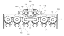
- FIGS. 12 and 13 are plan views for explaining the operation of a crop flow and inlet width control unit using a crop harvesting device for a tractor according to an embodiment of the present invention.
- the crop can be cut by the cutting portion (121) when guided by the guide portion (122) according to the movement of the tractor (not shown) (P1).
- the crop can move to the rear end of the cutting unit (121) while rotating according to the rotation direction of the cutting unit (121) (P2).
- the rotation direction of the cutting unit (121) can be different for each cutting unit (121) as shown in the drawing, and the direction shown in the drawing is intended to capture the crop as much as possible into the transport module (130), but is not intended to be limited thereto.
- the crops can be moved to the rear end of the cutting section (121) and then captured at the center of the rear end of the cutting section (121) and moved to the transport module (130) (P3).
- the width adjustment section (132) of the transport module (130) can be adjusted in width and the roller section (142) of the roller module (140) can be adjusted in height depending on the amount and size of the crops.
Landscapes
- Life Sciences & Earth Sciences (AREA)
- Environmental Sciences (AREA)
- Zoology (AREA)
- Engineering & Computer Science (AREA)
- Mechanical Engineering (AREA)
- Soil Sciences (AREA)
- Agricultural Machines (AREA)
- Harvesting Machines For Specific Crops (AREA)
Abstract
La présente invention concerne un appareil de récolte de cultures pour un tracteur, pouvant améliorer les performances d'insertion de cultures par réglage de la largeur et de la hauteur d'une partie d'entrée lorsque des cultures sont coupées et insérées dans un réservoir de traitement. La présente invention peut comprendre : un cadre de coupe qui est couplé à l'extrémité avant d'un tracteur et comprend une première partie de couplage et une seconde partie de couplage ; un module de coupe qui comprend une partie de coupe comprenant des lames de coupe, et une partie de guidage couplée à la partie de coupe ; un module de transport qui comprend une partie de transport comprenant une lame de transport, et des dispositifs de réglage de largeur d'insertion installés sur la partie de transport pour se faire face ; et un module de rouleau qui comprend une partie de fixation de rouleau couplée à la première partie de couplage, et une partie de rouleau disposée entre la paire de dispositifs de réglage de largeur d'insertion.
Applications Claiming Priority (2)
| Application Number | Priority Date | Filing Date | Title |
|---|---|---|---|
| KR10-2023-0075848 | 2023-06-13 | ||
| KR1020230075848A KR20240175638A (ko) | 2023-06-13 | 2023-06-13 | 트랙터용 작물 수확 장치 |
Publications (1)
| Publication Number | Publication Date |
|---|---|
| WO2024257975A1 true WO2024257975A1 (fr) | 2024-12-19 |
Family
ID=93852059
Family Applications (1)
| Application Number | Title | Priority Date | Filing Date |
|---|---|---|---|
| PCT/KR2023/020326 Ceased WO2024257975A1 (fr) | 2023-06-13 | 2023-12-11 | Appareil de récolte de cultures pour tracteur |
Country Status (2)
| Country | Link |
|---|---|
| KR (1) | KR20240175638A (fr) |
| WO (1) | WO2024257975A1 (fr) |
Citations (5)
| Publication number | Priority date | Publication date | Assignee | Title |
|---|---|---|---|---|
| JPH0767435A (ja) * | 1993-09-01 | 1995-03-14 | Bunmei Noki Kk | 葉タバコ収穫機 |
| KR200466126Y1 (ko) * | 2012-06-29 | 2013-04-03 | 박정규 | 예취기용 디스크장치 |
| KR101623846B1 (ko) * | 2016-03-16 | 2016-06-07 | 박정규 | 농업용 다기능 예취기 |
| JP2017006078A (ja) * | 2015-06-24 | 2017-01-12 | 井関農機株式会社 | 作物引抜機 |
| KR101712128B1 (ko) * | 2014-12-05 | 2017-03-06 | 오페주식회사 | 콤바인용 예취장치 |
Family Cites Families (1)
| Publication number | Priority date | Publication date | Assignee | Title |
|---|---|---|---|---|
| KR101282927B1 (ko) | 2012-07-04 | 2013-07-08 | 남미정 | 트랙터용 전방형 농산물수확기 |
-
2023
- 2023-06-13 KR KR1020230075848A patent/KR20240175638A/ko not_active Ceased
- 2023-12-11 WO PCT/KR2023/020326 patent/WO2024257975A1/fr not_active Ceased
Patent Citations (5)
| Publication number | Priority date | Publication date | Assignee | Title |
|---|---|---|---|---|
| JPH0767435A (ja) * | 1993-09-01 | 1995-03-14 | Bunmei Noki Kk | 葉タバコ収穫機 |
| KR200466126Y1 (ko) * | 2012-06-29 | 2013-04-03 | 박정규 | 예취기용 디스크장치 |
| KR101712128B1 (ko) * | 2014-12-05 | 2017-03-06 | 오페주식회사 | 콤바인용 예취장치 |
| JP2017006078A (ja) * | 2015-06-24 | 2017-01-12 | 井関農機株式会社 | 作物引抜機 |
| KR101623846B1 (ko) * | 2016-03-16 | 2016-06-07 | 박정규 | 농업용 다기능 예취기 |
Also Published As
| Publication number | Publication date |
|---|---|
| KR20240175638A (ko) | 2024-12-20 |
Similar Documents
| Publication | Publication Date | Title |
|---|---|---|
| WO2024257975A1 (fr) | Appareil de récolte de cultures pour tracteur | |
| WO2021054795A1 (fr) | Dispositif de séparation automatique d'abeilles | |
| CN115568341A (zh) | 摇轴组件以及圆形捆或模块构建机器和系统 | |
| WO2015068996A1 (fr) | Élément d'élimination de sève, unité de coupe pour dispositif de collecte de sève, et sève associée | |
| WO2024122706A1 (fr) | Appareil de récolte de cultures pour tracteur | |
| WO2017204444A2 (fr) | Dispositif de rotor de presse à balles | |
| CA2038783A1 (fr) | Dispositif de recolte | |
| US6408605B1 (en) | Cotton harvester row unit | |
| US5595052A (en) | Bat for a reel having an anti-wrap extension | |
| US5884464A (en) | Narrow row corn head with staggered height row units | |
| SE511557C2 (sv) | Applikator för löstagbar montering i en anslutningskrimpningsmaskin | |
| WO2013162155A1 (fr) | Dispositif de transfert de produits agricoles récoltés pour récolteuse-batteuse | |
| RS55008B1 (sr) | Adapter kombajna za berbu zrnastih useva, naročito kukuruza | |
| CN119213912A (zh) | 一种均匀撒布秸秆粉末的秸秆粉碎还田机 | |
| EP0846409B1 (fr) | Rouleau cueilleur à trois boulons de connexion | |
| CN112772126A (zh) | 一种间距可调式玉米梳脱摘穗割台 | |
| WO2012033391A2 (fr) | Moissonneuse polyvalente | |
| DE69207152T2 (de) | Apparat zum Herausziehen eines Bahnendes einer Bandwickelrolle | |
| JP3499422B2 (ja) | 普通形コンバイン | |
| WO2011059214A2 (fr) | Appareil destiné à la transformation de calamars | |
| WO2012077937A2 (fr) | Machine d'ensemencement | |
| WO2025105842A1 (fr) | Module de tondeuse pour tracteur | |
| WO2020251161A1 (fr) | Dispositif de prévention d'enroulement pour dispositif de coupe d'herbe et dispositif de coupe d'herbe l'utilisant | |
| JPH01317316A (ja) | テープ苗の分離装置 | |
| CN223694373U (zh) | 一种玉米收获机割台试验台夹持输送装置 |
Legal Events
| Date | Code | Title | Description |
|---|---|---|---|
| 121 | Ep: the epo has been informed by wipo that ep was designated in this application |
Ref document number: 23941756 Country of ref document: EP Kind code of ref document: A1 |
|
| NENP | Non-entry into the national phase |
Ref country code: DE |