WO2025005708A1 - Procédé et dispositif pour effectuer une communication sans fil à l'aide d'un récepteur de réveil à faible puissance - Google Patents
Procédé et dispositif pour effectuer une communication sans fil à l'aide d'un récepteur de réveil à faible puissance Download PDFInfo
- Publication number
- WO2025005708A1 WO2025005708A1 PCT/KR2024/009063 KR2024009063W WO2025005708A1 WO 2025005708 A1 WO2025005708 A1 WO 2025005708A1 KR 2024009063 W KR2024009063 W KR 2024009063W WO 2025005708 A1 WO2025005708 A1 WO 2025005708A1
- Authority
- WO
- WIPO (PCT)
- Prior art keywords
- terminal
- timer
- wake
- signal
- monitoring
- Prior art date
- Legal status (The legal status is an assumption and is not a legal conclusion. Google has not performed a legal analysis and makes no representation as to the accuracy of the status listed.)
- Ceased
Links
Images


Classifications
-
- Y—GENERAL TAGGING OF NEW TECHNOLOGICAL DEVELOPMENTS; GENERAL TAGGING OF CROSS-SECTIONAL TECHNOLOGIES SPANNING OVER SEVERAL SECTIONS OF THE IPC; TECHNICAL SUBJECTS COVERED BY FORMER USPC CROSS-REFERENCE ART COLLECTIONS [XRACs] AND DIGESTS
- Y02—TECHNOLOGIES OR APPLICATIONS FOR MITIGATION OR ADAPTATION AGAINST CLIMATE CHANGE
- Y02D—CLIMATE CHANGE MITIGATION TECHNOLOGIES IN INFORMATION AND COMMUNICATION TECHNOLOGIES [ICT], I.E. INFORMATION AND COMMUNICATION TECHNOLOGIES AIMING AT THE REDUCTION OF THEIR OWN ENERGY USE
- Y02D30/00—Reducing energy consumption in communication networks
- Y02D30/70—Reducing energy consumption in communication networks in wireless communication networks
Definitions
- the present embodiments propose a method and apparatus for performing wireless communication using a low-power wake-up receiver in a next-generation wireless access network (in this disclosure, “5G”, “NR [New Radio]”, “5G-Advanced”, “6G” or a subsequent 3GPP wireless access network).
- a next-generation wireless access network in this disclosure, “5G”, “NR [New Radio]”, “5G-Advanced”, “6G” or a subsequent 3GPP wireless access network.
- 3GPP continues to research and develop wireless communication technologies.
- energy efficiency of the terminal is also a very important consideration.
- terminals may need to be charged frequently depending on the individual's usage time. Designing for extended battery life of terminals is essential for improving energy efficiency and improving user experience. Energy efficiency is important for terminals that do not have a continuous energy source.
- Power consumption may vary depending on the configured wake-up period length. However, if DRX cycles with large values are used to meet battery life requirements, this may result in high latency, and may not be suitable for services that require both long battery life and low latency.
- Embodiments of the present disclosure can provide a method and device for performing wireless communication using a low-power wake-up receiver.
- the present embodiments may provide a method for a terminal to perform wireless communication using a low power wakeup receiver (LR), the method including: receiving configuration information for a low power wakeup operation; monitoring a wakeup signal (WUS) through the low power wakeup receiver based on the configuration information; starting a predetermined timer when the wakeup signal is received; and monitoring a downlink control channel through a transceiver when the timer is started.
- LR low power wakeup receiver
- the present embodiments can provide a method for a base station to control an operation of a terminal performing wireless communication using a low-power wake-up receiver, the method including the steps of transmitting configuration information for a low-power wake-up operation, transmitting a wake-up signal (WUS) to the terminal based on the configuration information when downlink data to be transmitted to the terminal is confirmed, and transmitting a downlink control channel for transmitting the downlink data.
- WUS wake-up signal
- the present embodiments provide a terminal for performing wireless communication using a low power wakeup receiver (LR), the terminal including a low power wakeup receiver, a transceiver, and a controller for controlling operations of the low power wakeup receiver and the transceiver, wherein the controller receives configuration information for a low power wakeup operation, monitors a wakeup signal (WUS) through the low power wakeup receiver based on the configuration information, starts a predetermined timer when the wakeup signal is received, and monitors a downlink control channel through the transceiver when the timer is started.
- LR low power wakeup receiver
- WUS wakeup signal
- the present embodiments provide a base station for controlling the operation of a terminal performing wireless communication using a low-power wake-up receiver, the base station including a transmitter, a receiver, and a controller for controlling the operations of the transmitter and the receiver, wherein the controller transmits configuration information for a low-power wake-up operation, and when downlink data to be transmitted to the terminal is confirmed, transmits a wakeup signal (WUS) to the terminal based on the configuration information, and transmits a downlink control channel for transmitting the downlink data.
- WUS wakeup signal
- a method and device for performing wireless communication using a low-power wake-up receiver capable of performing a wake-up operation that consumes power efficiently can be provided.
- the terminal when a terminal that wants to minimize power consumption monitors downlink signals using only an ultra-low-power receiver separate from a main radio (MR) transceiver such as NR, the terminal can minimize power consumption by recognizing that the terminal has been awakened due to unintended WUS reception from the base station and quickly terminating monitoring with the MR transceiver.
- MR main radio
- the terminal and base station can quickly recognize a receiver mode mismatch situation that may occur between the terminal and the base station, the communication disconnection problem between the terminal and the base station can be solved.
- FIG. 1 is a diagram briefly illustrating the structure of an NR wireless communication system to which the present embodiment can be applied.
- FIG. 2 is a drawing for explaining a frame structure in an NR system to which the present embodiment can be applied.
- FIG. 3 is a diagram for explaining a resource grid supported by a wireless access technology to which the present embodiment can be applied.
- FIG. 4 is a diagram for explaining a bandwidth part supported by a wireless access technology to which the present embodiment can be applied.
- FIG. 5 is a diagram exemplarily illustrating a synchronization signal block in a wireless access technology to which the present embodiment can be applied.
- FIG. 6 is a diagram for explaining a random access procedure in a wireless access technology to which the present embodiment can be applied.
- Figure 7 is a drawing for explaining CORESET.
- FIG. 9 is a diagram illustrating a procedure for a base station to control the operation of a terminal performing wireless communication using a low-power wake-up receiver according to one embodiment.
- FIG. 10 is a diagram for explaining a low-power wake-up operation using a timer of a terminal according to one embodiment.
- FIG. 11 is a diagram for explaining a low-power wake-up operation using a timer of a terminal and a base station according to one embodiment.
- FIG. 12 is a diagram for explaining a low-power wake-up operation when a timer of a terminal expires according to one embodiment.
- FIG. 13 is a diagram for explaining a low-power wake-up operation when the timer of a terminal and a base station expires according to one embodiment.
- FIG. 14 is a diagram for explaining a low-power wake-up operation according to an LR mode switching instruction according to one embodiment.
- FIG. 15 is a diagram for explaining a low-power wake-up operation when a timer according to one embodiment is set as a timer for entering LR mode.
- Fig. 17 is a diagram showing the configuration of a base station according to another embodiment.
- first, second, A, B, (a), (b), etc. may be used. These terms are only intended to distinguish the components from other components, and the nature, order, sequence, or number of the components are not limited by the terms.
- temporal chronological relationship or the chronological flow relationship when the temporal chronological relationship or the chronological flow relationship is described as “after”, “following”, “next to”, or “before”, it can also include cases where it is not continuous, as long as “immediately” or “directly” is not used.
- the numerical value or its corresponding information may be interpreted as including an error range that may occur due to various factors (e.g., process factors, internal or external impact, noise, etc.).
- the wireless communication system in this specification means a system for providing various communication services, such as voice and data packets, using wireless resources, and may include a terminal, a base station, or a core network.
- the embodiments disclosed below can be applied to wireless communication systems using various wireless access technologies.
- the embodiments can be applied to various wireless access technologies such as CDMA (code division multiple access), FDMA (frequency division multiple access), TDMA (timedivision multiple access), OFDMA (orthogonal frequency division multiple access), SC-FDMA (singlecarrier frequency division multiple access), or NOMA (non-orthogonal multiple access).
- the wireless access technology may mean not only a specific access technology, but also each generational communication technology established by various communication agreement organizations such as 3GPP, 3GPP2, WiFi, Bluetooth, IEEE, and ITU.
- CDMA can be implemented with a wireless technology such as UTRA (universal terrestrial radio access) or CDMA2000.
- TDMA can be implemented with a wireless technology such as GSM (global system for mobile communications)/GPRS (general packet radio service)/EDGE (enhanced datarates for GSM evolution).
- OFDMA can be implemented in wireless technologies such as IEEE (Institute of Electrical and Electronic Engineers) 802.11 (Wi-Fi), IEEE 802.16 (WiMAX), IEEE 802-20, E-UTRA (evolved UTRA), etc.
- IEEE 802.16m is an evolution of IEEE 802.16e and provides backward compatibility with systems based on IEEE 802.16e.
- UTRA is a part of UMTS (universal mobile telecommunications system).
- the terminal in this specification is a comprehensive concept meaning a device including a wireless communication module that performs communication with a base station in a wireless communication system, and should be interpreted as a concept including not only UE (User Equipment) in WCDMA, LTE, NR, HSPA, and IMT-2020 (5G or New Radio), but also MS (Mobile Station), UT (User Terminal), SS (Subscriber Station), and wireless device in GSM.
- the terminal may be a user portable device such as a smart phone depending on the usage type, and in a V2X communication system, it may mean a vehicle, a device including a wireless communication module in a vehicle, etc.
- a Machine Type Communication system it may mean an MTC terminal, M2M terminal, URLLC terminal, etc. equipped with a communication module to perform machine type communication.
- the base station or cell in this specification refers to an end that communicates with a terminal in terms of a network, and includes a Node-B, an evolved Node-B (eNB), a gNode-B (gNB), a Low Power Node (LPN), a sector, a site, various types of antennas, a Base Transceiver System (BTS), an Access Point, points (e.g., a transmission point, a reception point, a transceiver point), a relay node, a mega cell, a macro cell, a micro cell, a pico cell, a femto cell, a Remote Radio Head (RRH), a Radio Unit (RU), a small cell, and various coverage areas.
- a cell may mean a BWP (Bandwidth Part) in a frequency domain.
- a serving cell may mean an Activation BWP of a terminal.
- the various cells listed above have a base station that controls one or more cells, so the base station can be interpreted in two meanings. 1) It can be a device itself that provides a mega cell, a macro cell, a micro cell, a pico cell, a femto cell, or a small cell in relation to a wireless area, or 2) It can indicate the wireless area itself. In 1), all devices that provide a given wireless area are controlled by the same entity or interact to cooperatively configure the wireless area are all indicated as a base station. Depending on the configuration method of the wireless area, a point, a transceiver point, a transmission point, a reception point, etc. become an embodiment of a base station. In 2), the wireless area itself that receives or transmits a signal from the perspective of a user terminal or a neighboring base station can also be indicated as a base station.
- a cell may mean a component carrier having coverage of a signal transmitted from a transmission/reception point or coverage of a signal transmitted from a transmission/reception point, or the transmission/reception point itself.
- Uplink refers to a method of transmitting and receiving data from a terminal to a base station
- downlink refers to a method of transmitting and receiving data from a base station to a terminal
- Downlink may refer to communication or a communication path from multiple transmission/reception points to a terminal
- uplink may refer to communication or a communication path from a terminal to multiple transmission/reception points.
- the transmitter in the downlink, the transmitter may be part of the multiple transmission/reception points, and the receiver may be part of the terminal.
- the transmitter in the uplink, the transmitter may be part of the terminal, and the receiver may be part of the multiple transmission/reception points.
- Uplink and downlink transmit and receive control information through control channels such as PDCCH (Physical Downlink Control CHannel) and PUCCH (Physical Uplink Control CHannel), and transmit and receive data by configuring data channels such as PDSCH (Physical Downlink Shared CHannel) and PUSCH (Physical Uplink Shared CHannel).
- control channels such as PDCCH (Physical Downlink Control CHannel) and PUCCH (Physical Uplink Control CHannel)
- PDSCH Physical Uplink Shared CHannel
- PUSCH Physical Uplink Shared CHannel
- 3GPP After studying 4G (4th-Generation) communication technology, 3GPP develops 5G (5th-Generation) communication technology to meet the requirements of the next-generation wireless access technology of the ITU-R. Specifically, 3GPP develops LTE-A pro, which enhances LTE-Advanced technology to meet the requirements of the ITU-R, as a 5G communication technology, and NR, a new communication technology separate from 4G communication technology. Both LTE-A pro and NR refer to 5G communication technology, and in the following, 5G communication technology is explained with NR as the center, unless a specific communication technology is specified.
- the operating scenario in NR defines various operation scenarios by adding considerations for satellites, automobiles, and new verticals to the existing 4G LTE scenario, and supports the eMBB (Enhanced Mobile Broadband) scenario in terms of service, the mMTC (Massive Machine Communication) scenario that has high terminal density but is deployed over a wide area and requires low data rate and asynchronous access, and the URLLC (Ultra Reliability and Low Latency) scenario that requires high responsiveness and reliability and can support high-speed mobility.
- eMBB Enhanced Mobile Broadband
- mMTC Massive Machine Communication
- URLLC Ultra Reliability and Low Latency
- NR introduces a wireless communication system that applies new waveform and frame structure technologies, low latency technologies, ultra-high frequency band (mmWave) support technologies, and forward compatibility technologies.
- mmWave ultra-high frequency band
- the NR system presents various technological changes in terms of flexibility to provide forward compatibility. The main technological features of NR are explained below with reference to the drawings.
- Figure 1 is a schematic diagram illustrating the structure of an NR system to which the present embodiment can be applied.
- the NR system is divided into 5GC (5G Core Network) and NR-RAN parts, and the NG-RAN is composed of gNBs and ng-eNBs that provide user plane (SDAP/PDCP/RLC/MAC/PHY) and control plane (RRC) protocol termination for UE (User Equipment).
- the gNBs or the gNBs and ng-eNBs are interconnected via the Xn interface.
- the gNBs and ng-eNBs are each connected to the 5GC via the NG interface.
- the 5GC can be configured to include the AMF (Access and Mobility Management Function) that is in charge of the control plane such as terminal access and mobility control functions, and the UPF (User Plane Function) that is in charge of the control function for user data.
- AMF Access and Mobility Management Function
- UPF User Plane Function
- NR includes support for both frequency bands below 6 GHz (FR1, Frequency Range 1) and frequency bands above 6 GHz (FR2, Frequency Range 2).
- gNB refers to a base station that provides NR user plane and control plane protocol termination to terminals
- ng-eNB refers to a base station that provides E-UTRA user plane and control plane protocol termination to terminals.
- the base station described in this specification should be understood to encompass gNB and ng-eNB, and may also be used to refer to gNB or ng-eNB separately as needed.
- OFDM uses CP-OFDM waveforms with cyclic prefix for downlink transmission, and CP-OFDM or DFT-s-OFDM for uplink transmission.
- OFDM technology is easy to combine with MIMO (Multiple Input Multiple Output) and has the advantage of being able to use low-complexity receivers along with high frequency efficiency.
- MIMO Multiple Input Multiple Output
- the NR transmission numerology is determined based on the sub-carrier spacing and the cyclic prefix (CP), and is exponentially changed using the ⁇ value as an exponent value of 2 based on 15 kHz, as shown in Table 1 below.
- the numerology of NR can be divided into five types according to the subcarrier spacing. This is different from the subcarrier spacing of LTE, one of the 4G communication technologies, which is fixed to 15 kHz. Specifically, the subcarrier spacings used for data transmission in NR are 15, 30, 60, and 120 kHz, and the subcarrier spacings used for synchronization signal transmission are 15, 30, 12, and 240 kHz. In addition, the extended CP is applied only to the 60 kHz subcarrier spacing. Meanwhile, the frame structure in NR is defined as a frame with a length of 10 ms, which consists of 10 subframes with the same length of 1 ms.
- One frame can be divided into half frames of 5 ms, and each half frame includes 5 subframes.
- one subframe consists of one slot
- each slot consists of 14 OFDM symbols.
- FIG. 2 is a diagram for explaining a frame structure in an NR system to which the present embodiment can be applied.
- a slot is fixedly composed of 14 OFDM symbols in the case of a normal CP, but the length of the slot in the time domain may vary depending on the subcarrier spacing.
- a slot is composed of 1 ms, which is the same length as a subframe.
- a slot is composed of 14 OFDM symbols, but two slots can be included in one subframe with a length of 0.5 ms. That is, a subframe and a frame are defined with a fixed time length, and a slot is defined by the number of symbols, so the time length may vary depending on the subcarrier spacing.
- NR defines the basic unit of scheduling as a slot, and also introduces a mini-slot (or sub-slot, or non-slot based schedule) to reduce transmission delay in the wireless section.
- a mini-slot or sub-slot, or non-slot based schedule
- Using a wide subcarrier spacing reduces transmission delay in the wireless section because the length of one slot is shortened inversely.
- Mini-slots (or sub-slots) are for efficient support of URLLC scenarios, and scheduling is possible in units of 2, 4, and 7 symbols.
- NR defines uplink and downlink resource allocation at the symbol level within a single slot.
- a slot structure that can transmit HARQ ACK/NACK directly within a transmission slot is defined, and this slot structure is named and explained as a self-contained structure.
- NR is designed to support a total of 256 slot formats, of which 62 slot formats are used in 3GPP Rel-15. In addition, it supports a common frame structure that configures an FDD or TDD frame through various combinations of slots. For example, it supports a slot structure in which all symbols of a slot are set to downlink, a slot structure in which all symbols are set to uplink, and a slot structure in which downlink symbols and uplink symbols are combined. In addition, NR supports data transmission being distributed and scheduled to one or more slots. Therefore, a base station can inform a UE whether a slot is a downlink slot, an uplink slot, or a flexible slot using a slot format indicator (SFI). A base station can indicate a slot format by indicating an index of a table configured through UE-specific RRC signaling using SFI, and can also indicate it dynamically through DCI (Downlink Control Information) or statically or semi-statically through RRC.
- DCI Downlink Control Information
- antenna ports In relation to physical resources in NR, antenna ports, resource grids, resource elements, resource blocks, and bandwidth parts are considered.
- Antenna ports are defined such that the channel through which a symbol on an antenna port is carried can be inferred from the channel through which another symbol on the same antenna port is carried.
- Two antenna ports are said to be in a QC/QCL (quasi co-located or quasi co-location) relationship if large-scale properties of the channel through which a symbol on one antenna port is carried can be inferred from the channel through which a symbol on the other antenna port is carried.
- the large-scale properties include one or more of delay spread, Doppler spread, frequency shift, average received power, and received timing.
- FIG. 3 is a diagram for explaining a resource grid supported by a wireless access technology to which the present embodiment can be applied.
- a resource grid may exist for each numeral because NR supports multiple numerals in the same carrier.
- a resource grid may exist for each antenna port, subcarrier spacing, and transmission direction.
- a resource block consists of 12 subcarriers and is defined only in the frequency domain.
- a resource element consists of one OFDM symbol and one subcarrier. Therefore, as shown in Fig. 3, the size of one resource block can vary depending on the subcarrier spacing.
- NR defines "Point A", which serves as a common reference point for the resource block grid, common resource blocks, virtual resource blocks, etc.
- FIG. 4 is a diagram for explaining a bandwidth part supported by a wireless access technology to which the present embodiment can be applied.
- a bandwidth part can be designated within the carrier bandwidth for use by the terminal.
- a bandwidth part is linked to one numerology and consists of a subset of consecutive common resource blocks, and can be dynamically activated over time.
- a terminal is configured with up to four bandwidth parts for each of the uplink and downlink, and data is transmitted and received using the bandwidth part activated at a given time.
- the uplink and downlink bandwidth parts are set independently, and in the case of an unpaired spectrum, the bandwidth parts of the downlink and uplink are set as pairs so that they can share a center frequency to prevent unnecessary frequency re-tuning between downlink and uplink operations.
- a terminal performs cell search and random access procedures to connect to a base station and perform communication.
- Cell search is a procedure in which a terminal synchronizes to a cell of a corresponding base station, obtains a physical layer cell ID, and obtains system information using a synchronization signal block (SSB) transmitted by the base station.
- SSB synchronization signal block
- FIG. 5 is a diagram exemplarily illustrating a synchronization signal block in a wireless access technology to which the present embodiment can be applied.
- the SSB is composed of a primary synchronization signal (PSS) and a secondary synchronization signal (SSS), each of which occupies 1 symbol and 127 subcarriers, and a PBCH that spans 3 OFDM symbols and 240 subcarriers.
- PSS primary synchronization signal
- SSS secondary synchronization signal
- the terminal receives SSB by monitoring SSB in the time and frequency domain.
- SSB can be transmitted up to 64 times during 5ms. Multiple SSBs are transmitted with different transmission beams within 5ms, and the terminal performs detection assuming that SSBs are transmitted every 20ms based on a specific beam used for transmission.
- the number of beams that can be used for SSB transmission within 5ms can increase as the frequency band increases. For example, up to 4 SSB beams can be transmitted below 3GHz, up to 8 different beams can be used for SSB transmission in the frequency band of 3 to 6GHz, and up to 64 different beams can be used for SSB transmission in the frequency band of 6GHz or higher.
- SSB contains two in one slot, and the start symbol and repetition number within the slot are determined as follows depending on the subcarrier spacing.
- SSB unlike SS of conventional LTE, is not transmitted at the center frequency of the carrier bandwidth. That is, SSB can be transmitted even in a location other than the center of the system band, and multiple SSBs can be transmitted on the frequency domain when wideband operation is supported. Accordingly, the terminal monitors SSB using the synchronization raster, which is a candidate frequency location for monitoring SSB.
- the carrier raster and synchronization raster which are center frequency location information of the channel for initial access, are newly defined in NR, and the synchronization raster can support fast SSB search of the terminal because the frequency interval of the synchronization raster is set wider than that of the carrier raster.
- a terminal can obtain a MIB through a PBCH of an SSB.
- the MIB Master Information Block
- the MIB includes minimum information for the terminal to receive remaining system information (RMSI, Remaining Minimum System Information) broadcast by the network.
- the PBCH may include information on the position of a first DM-RS symbol in the time domain, information for the terminal to monitor SIB1 (e.g., SIB1 numerology information, information related to SIB1 CORESET, search space information, PDCCH related parameter information, etc.), offset information between a common resource block and an SSB (the absolute position of an SSB within a carrier is transmitted through SIB1), etc.
- the SIB1 numerology information is equally applied to some messages used in a random access procedure for accessing a base station after the terminal completes a cell search procedure.
- the numerology information of SIB1 may be applied to at least one of messages 1 to 4 for the random access procedure.
- the aforementioned RMSI may mean SIB1 (System Information Block 1), and SIB1 is broadcasted periodically (ex, 160 ms) in the cell.
- SIB1 includes information required for the terminal to perform an initial random access procedure, and is transmitted periodically through PDSCH.
- the terminal In order for the terminal to receive SIB1, it must receive numerology information used for transmitting SIB1 and CORESET (Control Resource Set) information used for scheduling SIB1 through PBCH.
- the terminal checks scheduling information for SIB1 using SI-RNTI in CORESET, and acquires SIB1 on PDSCH according to the scheduling information.
- the remaining SIBs except SIB1 may be transmitted periodically or may be transmitted according to the request of the terminal.
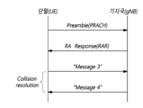
- FIG. 6 is a diagram for explaining a random access procedure in a wireless access technology to which the present embodiment can be applied.
- the terminal transmits a random access preamble for random access to the base station.
- the random access preamble is transmitted through PRACH.
- the random access preamble is transmitted to the base station through PRACH, which consists of consecutive radio resources in a specific slot that is repeated periodically.
- PRACH which consists of consecutive radio resources in a specific slot that is repeated periodically.
- BFR beam failure recovery
- a terminal receives a random access response to a transmitted random access preamble.
- the random access response may include a random access preamble identifier (ID), an UL Grant (uplink radio resource), a temporary C-RNTI (Temporary Cell - Radio Network Temporary Identifier) and a TAC (Time Alignment Command). Since one random access response may include random access response information for one or more terminals, the random access preamble identifier may be included to indicate to which terminal the included UL Grant, temporary C-RNTI and TAC are valid.
- the random access preamble identifier may be an identifier for a random access preamble received by a base station.
- the TAC may be included as information for the terminal to adjust uplink synchronization.
- the random access response may be indicated by a random access identifier on a PDCCH, i.e., an RA-RNTI (Random Access - Radio Network Temporary Identifier).
- the terminal that receives a valid random access response processes the information contained in the random access response and performs scheduled transmission to the base station. For example, the terminal applies TAC and stores a temporary C-RNTI. In addition, it transmits data stored in the terminal's buffer or newly generated data to the base station using the UL Grant. In this case, information that can identify the terminal must be included.
- the terminal receives a downlink message for contention resolution.
- the downlink control channel in NR is transmitted in a CORESET (Control Resource Set) with a length of 1 to 3 symbols, and transmits uplink/downlink scheduling information, SFI (Slot format Index), and TPC (Transmit Power Control) information.
- CORESET Control Resource Set
- SFI Slot format Index
- TPC Transmit Power Control
- CORESET Control Resource Set
- a terminal can decode control channel candidates using one or more search spaces in the CORESET time-frequency resources.
- a QCL (Quasi CoLocation) assumption is set for each CORESET, and this is used for the purpose of informing the characteristics of the analog beam direction in addition to the delay spread, Doppler spread, Doppler shift, and average delay, which are the characteristics assumed by the conventional QCL.
- Figure 7 is a drawing for explaining CORESET.
- a CORESET can exist in various forms within a carrier bandwidth within one slot, and a CORESET can consist of a maximum of three OFDM symbols in the time domain.
- a CORESET is defined as a multiple of six resource blocks up to the carrier bandwidth in the frequency domain.
- the first CORESET is indicated via MIB as part of the initial bandwidth part configuration to enable receiving additional configuration information and system information from the network.
- the terminal After establishing a connection with the base station, the terminal can receive and configure one or more CORESET information via RRC signaling.
- an arbitrary LTE operator could configure a bandwidth of a minimum of 1.4 MHz and a maximum of 20 MHz when configuring an LTE CC, and a normal LTE terminal supported a transmission/reception capability of 20 MHz bandwidth for an LTE CC.
- bandwidth parts BWPs, bandwidth part(s)
- segmented bandwidths are configured for any NR CC, and it is required to support flexible wider bandwidth operation through different bandwidth part configurations and activations for each terminal.
- one or more bandwidth parts can be configured through one serving cell configured from a terminal perspective, and the terminal is defined to activate one downlink bandwidth part (DL bandwidth part) and one uplink bandwidth part (UL bandwidth part) in the serving cell to use them for uplink/downlink data transmission and reception.
- DL bandwidth part downlink bandwidth part
- UL bandwidth part uplink bandwidth part
- it is defined to activate one downlink bandwidth part and/or uplink bandwidth part for each serving cell to use the radio resources of the serving cell to use them for uplink/downlink data transmission and reception.
- an initial bandwidth part for an initial access procedure of a UE in a given serving cell is defined, one or more UE-specific bandwidth part(s) are configured for each UE through dedicated RRC signaling, and a default bandwidth part for a fallback operation can also be defined for each UE.
- frequencies, frames, subframes, resources, resource blocks, regions, bands, subbands, control channels, data channels, synchronization signals, various reference signals, various signals or various messages related to NR may be interpreted as having past or present meanings or various meanings used in the future.
- Power consumption may vary depending on the configured wake-up period length. However, if a large value of discontinuous reception (DRX) cycle is used to meet battery life requirements, the resulting high latency may not be suitable for services that require both long battery life and low latency.
- DRX discontinuous reception
- the UE needs to wake up periodically once per DRX cycle, which dictates the power consumption during periods of no signal or data traffic. Power consumption can be significantly reduced if the UE can wake up only when triggered, such as paging. This can be achieved by using a wake-up signal that triggers the main radio and a separate receiver that can monitor the wake-up signal with ultra-low power consumption.
- the main radio operates to transmit and receive data, and can be turned off or set to maximum power saving mode unless it is turned on.
- the power consumption for monitoring the wake-up signal may vary depending on the wake-up signal design and the hardware module of the wake-up receiver used to detect and process the signal.
- a Main Radio may be used to mean a Tx/Rx module, i.e., a transmitter, a receiver, or a transceiver, that operates for NR signals/channels in addition to low-power wake-up related signals/channels.
- a Low-Power Wake-Up Receiver LP-WUR; LR
- the MR mode may mean performing communication in the Main Radio
- the LR mode may mean performing communication using the low-power wake-up receiver.
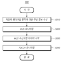
- FIG. 8 is a diagram illustrating a procedure (800) in which a terminal performs wireless communication using a low-power wake-up receiver according to one embodiment.
- the terminal can receive configuration information for a low-power wake-up operation (S810).
- a terminal may receive at least one configuration information that configures parameters used to perform a low-power wake-up operation described in the present disclosure from a base station.
- the parameters may include, for example, a monitoring period of a wake-up signal in an LR mode, monitoring occasion information, PDCCH monitoring information in an MR mode, setting information for switching between each mode, and the like.
- the configuration information for the low-power wake-up operation may include information that configures a low-power wake-up signal (LP-WUS).
- the low-power wake-up signal may be configured separately from a wake-up signal used in a conventional DRX operation.
- the configuration information for the low-power wake-up operation may include configuration information for an operation of a low-power wake-up receiver (LP-WUR; LR).
- the configuration information may be received via higher layer signaling, such as RRC signaling.
- the configuration information for the low-power wake-up operation may include configuration information for at least one timer used in the low-power wake-up operation.
- the timer may be set to a duration for monitoring a downlink control channel (PDCCH) via the MR after a wake-up signal is received via the LR.
- the timer may be set to a duration for starting or restarting after a downlink signal, i.e., a wake-up signal or a PDCCH, is received via the LR or MR, and entering the LR mode if no downlink signal is received.
- a downlink signal i.e., a wake-up signal or a PDCCH
- the terminal can monitor a wakeup signal (WUS) through a low-power wakeup receiver based on configuration information (S820).
- WUS wakeup signal
- S820 configuration information
- the terminal may switch to the LR mode based on configuration information for the low-power wake-up operation. For example, when the terminal receives an instruction to switch to the LR mode from the base station, the terminal may monitor whether a wake-up signal is transmitted from the base station through a low-power wake-up receiver corresponding to LR. Or, for another example, when a timer associated with the switch to the LR mode is configured, the terminal may switch to the LR mode according to the setting of the timer.
- the terminal When the terminal switches to the LR mode, it can monitor a wake-up signal through a low-power wake-up receiver without performing wireless communication according to MR. Based on the configuration information for the low-power wake-up operation, the terminal can perform monitoring of the wake-up signal until the wake-up signal is received.
- the terminal may perform operations related to radio resource management (RRM) related to the wake-up signal. For example, operations such as receiving and measuring a reference signal related to RRM may be performed.
- RRM radio resource management
- the terminal can start a predetermined timer when a wake-up signal is received (S830).
- the terminal can receive a wake-up signal transmitted from a base station by performing monitoring according to configuration information for a low-power wake-up operation.
- the terminal can start a LR mode transition timer.
- the LR mode transition timer can be set to a period for monitoring a downlink control channel through MR after a wake-up signal is received through LR.
- the LR mode transition timer can be set to a period for starting or restarting after a wake-up signal or a downlink control channel is received, and entering the LR mode if a downlink signal is not received.
- the timers in the two cases described above can be configured as only one timer, or can be configured together as separate timers.
- the terminal can monitor the downlink control channel through the transceiver when the timer starts (S830).
- the terminal can monitor whether a PDCCH is transmitted from the base station by turning on the transceiver corresponding to the MR while the LR mode transition timer is operating.
- the transceiver is not limited to one device, and may be composed of each device corresponding to a transmitter and a receiver.
- monitoring of a wake-up signal and monitoring of a downlink control channel can be performed simultaneously while a timer is running. That is, even if the terminal starts monitoring a PDCCH through a transceiver, it can continue monitoring the wake-up signal through a low-power wake-up receiver.
- the terminal can stop the timer and perform wireless communication through the transceiver.
- the terminal can stop the LR mode transition timer and turn off the low-power wake-up receiver. That is, when a PDCCH is received, the terminal can stop monitoring for a wake-up signal.
- the NR DRX operation can be performed by starting the DRX inactivity timer. Or, if the terminal is in the RRC Idle state, it can be switched to the connected state through paging reception. After that, data can be transmitted and received with the base station through the transceiver in the MR mode.
- the terminal may stop monitoring the downlink control channel.
- the terminal may turn off the transceiver and continue monitoring the low-power wake-up signal that was being performed. In other words, the terminal may perform operations in the LR mode.
- the terminal may stop monitoring the downlink control channel. That is, even while the LR mode transition timer is running, if a LR mode transition instruction is received from the base station, the terminal may turn off the transceiver. Accordingly, the terminal may continue to monitor the low power wake-up signal that it was performing. That is, the terminal may perform operations in the LR mode.
- the timer may be configured to restart if a wake-up signal or a downlink control channel is received while the timer is in operation.
- the LR mode transition timer may be configured to restart even if other downlink data is received in addition to the wake-up signal or the downlink control channel. If the LR mode transition timer expires without receiving any downlink data, the terminal may transition to the LR mode.
- monitoring of the wakeup signal and the downlink control channel by the terminal may be set to be continuously performed.
- the terminal may restart the LR mode transition timer and turn on the transceiver to monitor the PDCCH. Thereafter, when a wakeup signal is received while the LR mode transition timer is operating, the terminal may restart the LR mode transition timer and continuously perform monitoring of the wakeup signal and the downlink control channel.
- the terminal can transition to LR mode.
- a method and device for performing wireless communication using a low-power wake-up receiver capable of performing a wake-up operation that consumes power efficiently can be provided.
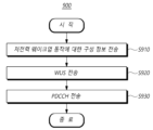
- FIG. 9 is a diagram illustrating a procedure (900) for controlling the operation of a terminal performing wireless communication using a low-power wake-up receiver by a base station according to one embodiment.
- the description given above in FIG. 8 may be omitted to avoid redundant description, and in this case, the omitted content may be substantially equally applied to the base station as long as it does not contradict the technical idea of the invention.
- the base station can transmit configuration information for low-power wake-up operation (S910).
- a base station may receive at least one configuration information that configures parameters used to perform a low-power wake-up operation described in the present disclosure to a terminal.
- the parameters may include, for example, a monitoring period of a wake-up signal in an LR mode, monitoring occasion information, PDCCH monitoring information in an MR mode, setting information for switching between each mode, and the like.
- the configuration information for the low-power wake-up operation may include information that configures a low-power wake-up signal (LP-WUS).
- the low-power wake-up signal may be configured separately from a wake-up signal used in a conventional DRX operation.
- the configuration information for the low-power wake-up operation may include configuration information for an operation of a low-power wake-up receiver (LP-WUR; LR).
- the configuration information may be transmitted via higher layer signaling, such as RRC signaling.
- Configuration information for a low-power wake-up operation may include configuration information for at least one timer used in the low-power wake-up operation.
- the base station may instruct the terminal to switch to the LR mode based on the configuration information for the low-power wake-up operation.
- the base station may transmit an instruction to switch to the LR mode to the terminal so that the terminal may monitor a wake-up signal via a low-power wake-up receiver.
- the base station may recognize that the terminal has switched to the LR mode based on the setting of the timer.
- the base station can transmit a wake-up signal to the terminal.
- the base station can transmit a downlink control channel for transmitting downlink data (S930).
- the base station can perform NR DRX operation while starting the DRX inactivity timer. Or, if the terminal is in the RRC Idle state, the base station can switch to the connected state through paging transmission. After that, data can be transmitted and received with the terminal through the transceiver in the MR mode.
- the base station when the base station transmits a wake-up signal, the base station may start a predetermined timer.
- an LR mode transition timer set individually for each terminal or set for each terminal group may be started.
- the LR mode transition timer may be set to a period during which the terminal monitors a downlink control channel via MR after receiving a wake-up signal via LR.
- the base station when it receives HARQ feedback information for transmission of downlink data, it can stop the timer and perform wireless communication with the terminal.
- the base station may retransmit the wake-up signal to the terminal. That is, if the HARQ feedback information is not received while the LR mode transition timer of the base station is operating, the LR mode transition timer expires. Accordingly, the base station may consider that the transmission of the downlink control channel and the associated downlink data to the terminal has failed, and may retransmit the wake-up signal in the LR mode.
- the base station may transmit a low power mode transition instruction to an unintended terminal among the terminal group to which the wake-up signal is transmitted. That is, if the wake-up signal is transmitted to a terminal group, the base station may individually transmit a low power mode transition instruction to a terminal that is not intended to be woken up. In this case, the base station may transmit a wake-up signal in LR mode to the corresponding terminal.
- the base station can restart the timer and perform wireless communication with the terminal.
- the LR mode transition timer is set to a period in which it starts or restarts when a downlink signal is transmitted and enters the LR mode if HARQ feedback information is not received.
- the timers in the two cases described above may be configured with only one timer, or may be configured together as separate timers.
- the base station can transmit downlink data to the terminal in MR mode, and restart the LR mode transition timer whenever HARQ feedback information for the transmitted downlink data is received. Afterwards, when the LR mode transition timer expires, a wake-up signal can be transmitted to the terminal in LR mode.
- a method and device for performing wireless communication using a low-power wake-up receiver capable of performing a wake-up operation that consumes power efficiently can be provided.
- the present disclosure proposes a specific method for an operation to be performed after waking up when a terminal that seeks to minimize power consumption by using a low-power wake-up receiver (WUR) receives a wake-up signal (WUS) through the WUR.
- WUR low-power wake-up receiver
- a long sleep duration must be used to minimize power consumption of the terminal. While a long-duration DRX operation provides a way to minimize power consumption of the terminal, it is difficult to satisfy the delay requirements for terminals requiring low latency.
- a method is required to enable the terminal to receive a wake-up signal from the base station while consuming only the minimum power even in a short-duration or Always ON state. As one solution for this, an ultra-low power receiver that can be mounted separately from a conventional transceiver has been introduced.
- an ultra-low power receiver is defined as a receiver that can receive only a wake-up signal and essential signals related thereto, and as a receiver separate from a transceiver used for conventional data transmission and reception.
- the transceiver Main Radio, MR tx./rx. module
- the transceiver used to transmit and receive the conventional NR signal/channel is turned off, and only the LP wake-up receiver is turned on to receive only the wake-up signal and essential signals related thereto, thereby drastically reducing the power consumption of the terminal.
- the terminal that receives the wake-up signal through the corresponding receiver can be instructed to switch to the main radio (MR) mode, and the terminal instructed thus can switch the mode from LR to MR and perform communication through the transceiver for the conventional NR data transmission and reception.
- LR Low power wakeup Receiver
- LP-WUR can be configured to operate Always ON or Periodically ON. Additionally, LP-WUS/WUR operation can be considered for both RRC IDLE/INACTIVE and CONNECTED modes.
- the units that can be instructed via LP-WUS can all be considered, including instructions based on UE-group, subgroup, or UE ID (UE-ID).
- a terminal operating in LP-WUR(LR) mode can be defined as a separate method from the mode in which it operates as a conventional NR transceiver.
- the WUS reception method currently under consideration in the LR mode can operate UE-specifically or UE group-specifically. If UE-specific WUS resources are allocated, a large amount of resources are required because dedicated WUS resources must be allocated to each UE. Instead of allocating a large amount of WUS resources considering resource efficiency, a UE group-based WUS allocation method can also be considered. However, if WUS resources are allocated based on UE groups and unintended UEs belong to the group, all UEs in the group must be woken up in order to wake up specific UEs belonging to the group. In this case, since the undesired UEs belonging to the group perform unnecessary wake-ups, it will be helpful in reducing power consumption if they can be quickly put back to sleep.
- a situation may occur where a terminal wakes up by judging that it has received a WUS due to a false alarm even though the base station did not transmit a wake up signal.
- the wake up of the terminal can also be defined as an undesired UE.
- the terminal monitoring WUS through LR can stop monitoring WUS through LR and start monitoring PDCCH by switching to MR.
- a base station if a base station is not aware of this, if there is data to be transmitted to the terminal, it will attempt to wake up the terminal through the WUS allocated to the LP-WUR of the terminal before transmitting downlink data to MR. If the terminal stops monitoring WUS and only performs PDCCH monitoring for MR, communication disconnection may occur due to mode mismatch between the terminal and the base station. To prepare for such a situation, the terminal will need to continue monitoring the LR mode for a certain period of time before completing the switching to MR.
- a situation may occur where a base station transmits a WUS to a terminal that is intended to be woken up, and the terminal that receives it performs PDCCH monitoring to MR, but the terminal determines that it is a false alarm WUS due to an error in receiving downlink data from the base station. This may occur when the downlink data transmission of the base station is not successfully transmitted to the terminal for some reason (e.g., a downlink synchronization (DL synch) error), and the terminal switches back to the LR mode.
- DL synch downlink synchronization
- the terminal and the base station when an unintended terminal wakes up, a method is required for the terminal and the base station to quickly determine this and for the terminal to switch back to deep sleep/LR mode.
- the terminal when the terminal switches back to LR mode due to a reception error in the terminal despite the correct wake-up of the base station, the base station may not recognize the mode switch of the terminal and may cause an RLF situation due to continuous transmission failure. It is necessary for the terminal and the base station to recognize error problems due to mode mismatch in such various situations.
- the present disclosure proposes a specific method for resolving an error situation that may occur when an unintended terminal receives a wake up signal for a terminal that monitors WUS only through LP-WUR with the MR transceiver turned off based on the aforementioned contents, and for allowing the terminal and base station to quickly recognize this and re-switch to LR/deep sleep mode (or maintain LR ON state, or synchronize low-power receiver modes between each other).
- the present disclosure proposes a method for turning ON/OFF (i.e., PDCCH monitoring) the LP-WUR and MR modules of a terminal that receives a Wake Up Signal (WUS) through a Low-Power Wake Up Receiver (LP-WUR, LR). More specifically, when the terminal receives a WUS through the LP-WUR, it is proposed to set a timer (i.e., LR_transition_timer) to define a period for continuing downlink monitoring of LR and MR while maintaining the WUR in the ON state for a specific period of time even if the tx./rx. module of the main radio for data transmission and reception is powered ON.
- LR_transition_timer i.e., LR_transition_timer
- the terminal can monitor the downlink through two receivers with both LR and MR power turned ON while the timer is running. If the terminal successfully receives a PDCCH set to be monitored by the terminal through the MR while the timer is running, the terminal terminates the timer and turns OFF the receiver of the LP-WUR. That is, the WUS monitoring through the LP WUR is stopped.
- the PDCCH set to be monitored by the terminal may include at least a PDCCH transmitting a UE-specific DCI format CRC scrambled with C-RNTI, MCS-C-RNTI, SP-CSI-RNTI, CS-RNIT(s), SL-RNTI, SL-CS-RNTI or SL Semi-Persistent Scheduling V-RNTI, which is transmitted through CSS or USS set for the terminal.
- it may include at least a PDCCH transmitting a UE-group common DCI format CRC scrambled with MCCH-RNTI, G-RNTI or G-CS-RNTI, etc., which is transmitted via CSS for MBS. If an indicator indicating a transition to LR mode is received from the base station while the timer is running or the timer expires, it is proposed that the terminal powers off the MR module and switches to LR mode to maintain WUS monitoring.
- the terminal While the timer proposed in this disclosure is operating, the terminal keeps both the Wake-Up Receiver and the Main Radio Transceiver in the ON state, and continues the downlink monitoring set in each mode. If the terminal proposed in this disclosure receives a PDCCH transmitted to itself via MR while the timer is operating, the terminal turns OFF the LR receiver of the terminal and turns ON only the MR tx./rx. module. That is, the conventional NR operation is performed. If the proposed timer expires or the base station instructs to switch to the LP-WUR mode while the proposed timer is operating, the terminal turns OFF the MR tx/rx module (i.e., stops monitoring PDCCH via the MR module) and continues WUS monitoring via only LP-WUR. If a WUS is additionally received via LP-WUR while the timer is operating, the terminal can restart the timer and continue monitoring via MR and LR while the timer is operating as described above.
- the terminal when the terminal receives a WUS through LP-WUR, the terminal turns ON the power of the tx./rx. module of the main radio for data transmission and reception and switches the WUR to the OFF state at the same time. That is, the terminal always maintains the ON state for only one of the MR and LR radio modules, and determines the radio module to be activated based on whether the WUS is received, timer expiration, LR setting information, or LR activation/deactivation instruction information. Accordingly, when the LR mode is set for any terminal, or additionally, LR mode activation is instructed, the terminal maintains the LR on and MR off states. When the terminal receives a WUS from the base station through LR, the terminal turns off the LR and turns on the MR to monitor the PDCCH.
- the terminal turns off MR and turns on LR again to switch to the LR mode.
- the terminal that receives WUS in the LR mode and switches to the MR mode monitors PDCCH through MR and operates the timer for switching to the LR mode. If the terminal successfully receives the PDCCH set to be monitored by the terminal through MR while the timer is running, the terminal can restart the timer or stop the LR switching operation based on the timer. In the latter case, the terminal can enter the LR mode again by the explicit LR mode switching setting of the base station or the LR mode activation instruction information. In the former case, the terminal can enter the LR mode when the restarted timer expires or by explicit setting/instruction information of the terminal.
- the PDCCH set to be monitored by the terminal in the above may include at least a PDCCH transmitting a UE-specific DCI format CRC scrambling such as C-RNTI, MCS-C-RNTI, SP-CSI-RNTI, CS-RNIT(s), SL-RNTI, SL-CS-RNTI or SL Semi-Persistent Scheduling V-RNTI transmitted through CSS or USS set for the terminal.
- a PDCCH transmitting a UE-group common DCI format CRC scrambling such as MCCH-RNTI, G-RNTI or G-CS-RNTI transmitted through CSS for MBS.
- the timer proposed in this disclosure is a timer that starts when a WUS is received on a WUR, and while the timer is running, the terminal performs both WUS and PDCCH monitoring through LR and MR, and provides a period for maintaining the two modes simultaneously for the duration of the timer instead of performing an immediate switch from LR to MR.
- the timer proposed in the invention can be defined as the same timer as the timer for entering the LR mode from the MR mode. That is, the timer is defined as a timer that is (re)started when a PDCCH or a WUS is received in the MR or LR. If the terminal receives an LR-related configuration message including the LR_transition_timer from the base station, the terminal in the MR mode (re)starts the LR_transition_timer whenever it receives a PDCCH. When the timer expires, the terminal enters the LR mode.
- the terminal If the terminal receives a WUS in LR mode, it starts the LR_transition_timer, and if the terminal successfully receives a PDCCH that is set to be monitored by the terminal through MR (i.e., if the terminal successfully receives a DCI format based on RNTI that is set to be monitored by the terminal as described above), it restarts the LR_transition_timer.
- the timer is stopped.
- the terminal receives a WUS in the LR mode
- the LR_transition_timer is started, and if reception of a PDCCH that the terminal is configured to monitor through MR is successful (i.e., reception of an RNTI-based DCI format that the terminal is configured to monitor as described above is successful), the LR_transition_timer is stopped to maintain the MR mode until explicit LR mode transition setting or LR mode activation indication information is received from the base station.
- the above LR_transition_timer is a new timer, and the timer value for any terminal can be set by the base station.
- the LR-transition_timer can reuse an existing timer value.
- the DRX inactivity timer for DRX operation of the terminal can be utilized as the above LR_transition_timer.
- the above LR_transition_timer is set for each terminal or terminal group in the LR mode set to monitor a certain WUS, and when the corresponding WUS is transmitted by the base station, the base station can also activate the same timer value for the LR_transition_timer set for each terminal set to monitor the corresponding WUS. Through this, the base station can detect a PDCCH transmission/reception error of a terminal that needs to switch to MR mode according to WUS transmission according to the operation embodiment of the terminal according to WUS reception defined above, or synchronize terminals that have switched to MR mode according to WUS transmission and have switched back to LR mode according to timer expiration among the terminals.
- the proposed timer can also be applied to PDCCH transmission/reception errors on MR after WUS transmission/reception between the base station and the terminal. That is, this means that the proposed timer can operate not only at the terminal but also at the base station. Even if the transmission of the WUS was a correct transmission to the desired UE, if the base station does not receive any feedback (e.g., HARQ feedback for PDCCH) from the terminal during the proposed timer, it may correspond to the case where the terminal did not wake up for some reason, or woke up but did not receive PDCCH on MR. At this time, the terminal may have entered the LR mode again or may not have switched to the MR mode.
- any feedback e.g., HARQ feedback for PDCCH
- the base station may start the proposed timer when it transmits a WUS to the terminal, and may reattempt the WUS transmission to the LR receiver of the terminal when the timer expires. If, while the timer is running, any UL signal (e.g., HARQ feedback for DL data) is received from the terminal, the timer stops and the terminal's MR mode transition is recognized.
- any UL signal e.g., HARQ feedback for DL data
- a (maximum) time interval is defined between the time point at which the base station transmits a WUS on LR and the time point at which the PDCCH corresponding to the transmitted WUS is transmitted on MR, it is preferable that the value of the timer proposed in the present disclosure be set to a value greater than the time interval.
- an LR_transition_timer value for maintaining an MR activation state according to WUS reception and a timer-based LR mode transition according to the period may be set from the base station.
- the LR_transition_timer value may be set through a separate RRC parameter for the terminal set for LR-WUS monitoring, or may follow the DRX inactivity timer value as described above.
- the terminal activates MR to perform monitoring for PDCCH based on the RNTI set to be monitored by the terminal.
- the LR_transition_timer is operated while maintaining the dual activation mode state that maintains the activation state for LR, and if PDCCH reception is successful via MR before the timer expires, the timer can be spotted and switched to a complete MR state (i.e., switched LR to off state).
- the above LR_transition_timer allows the base station or the network to manage the timer value according to the setting value of each terminal, and when the LR_transition_timer is activated for any terminal, the base station or the network can operate the timer in synchronization with the timer count of the terminal based on the LR-transition_timer value set for the terminal. Accordingly, the base station or the network can synchronize the expiration and reset/restart of the LR-transition_timer for any terminal and synchronize whether or not to switch the LR mode accordingly.
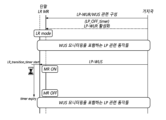
- Case 1 After receiving WUS, if PDCCH and/or PDSCH corresponding thereto set to be monitored by the terminal through MR is received (however, if both MR and LR are kept ON when receiving the above WUS) (case 1-1, 1-2)
- Case 1 describes two examples: a case where the timer is operated only in the terminal (case 1-1) and a case where the timer is operated together in both the base station and the terminal (case 1-2).
- Fig. 10 is a diagram for explaining a low-power wake-up operation using a timer of a terminal according to one embodiment. Referring to Fig. 10, the operations of the terminal and base station in case 1-1 are as follows.
- LR_transition_timer Duration to monitor PDCCH that can be transmitted to MR after receiving WUS via LR.
- the terminal continues to monitor downlink through both LR and MR while LR_transition_timer is running.
- NR DRX operation can be performed by starting the DRX inactivity timer.
- the state can be switched to connected by receiving paging.
- LP-WUR/WUS related configuration information including at least the following information:
- LR_transition_timer Duration to monitor PDCCH that can be transmitted to MR after receiving WUS via LR.
- the transition is recognized either through an LP-WUR/LP-WUS activation transmission or by a specific timer.
- NR DRX operation can be performed by starting the DRX inactivity timer.
- the state can be switched to connected through paging transmission.
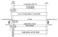
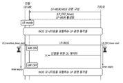
- Fig. 11 is a diagram for explaining a low-power wake-up operation using a timer of a terminal and a base station according to one embodiment. Referring to Fig. 11, the operations of the terminal and the base station in case 1-2 are as follows.
- LP-WUR/WUS related configuration information including at least the following information:
- LR_transition_timer Duration to monitor PDCCH that can be transmitted to MR after receiving WUS via LR.
- the transition is recognized either through an LP-WUR/LP-WUS activation transmission or by a specific timer.
- a WUS is transmitted to wake up the terminal.
- the LR_transition_timer set individually for each terminal set to monitor the WUS or set for each terminal group is started.
- the LR_transition_timer While the LR_transition_timer is running, if HARQ feedback for the transmitted DL data is received, the LR_transition_timer is stopped and communication is performed through the NR signal/channel.
- NR DRX operation can be performed by starting the DRX inactivity timer.
- the state can be switched to connected through paging transmission.
- Case 2 describes two examples: a case where the timer is operated only in the terminal, and a case where the timer is operated together in both the base station and the terminal.
- FIG. 12 is a diagram for explaining a low-power wake-up operation when a timer of a terminal expires according to one embodiment. Referring to FIG. 12, the operations of the terminal and the base station in case 2-1 are as follows.
- LR_transition_timer Duration to monitor PDCCH that can be transmitted to MR after receiving WUS via LR.
- Switching is done by LP-WUR/LP-WUS activation instruction from base station, or by a specific timer.
- the terminal continues to monitor downlink through both LR and MR while LR_transition_timer is running.
- the MR transceiver can be turned OFF.
- It may include WUS monitoring via LR receiver and WUS related RRM operations.
- LP-WUR/WUS related configuration information including at least the following information:
- LR_transition_timer Duration to monitor PDCCH that can be transmitted to MR after receiving WUS via LR.
- the transition is recognized either through an LP-WUR/LP-WUS activation transmission or by a specific timer.
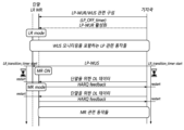
- FIG. 13 is a diagram for explaining a low-power wake-up operation when the timer of a terminal and a base station expires according to one embodiment. Referring to FIG. 13, the operations of the terminal and the base station in case 2-2 are as follows.
- LP-WUR/WUS related configuration information including at least the following information:
- LR_transition_timer Duration to monitor PDCCH that can be transmitted to MR after receiving WUS via LR.
- the transition is recognized either through an LP-WUR/LP-WUS activation transmission or by a specific timer.
- FIG. 14 is a diagram for explaining a low-power wake-up operation according to an LR mode switching instruction according to one embodiment. Referring to FIG. 14, the operations of the terminal and base station in case 3 are as follows.
- LR_transition_timer Duration to monitor PDCCH that can be transmitted to MR after receiving WUS via LR.
- Switching is done by LP-WUR/LP-WUS activation instruction from base station, or by a specific timer.
- the terminal continues to monitor downlink through both LR and MR while LR_transition_timer is running.
- It may include WUS monitoring via LR receiver and WUS related RRM operations.
- LP-WUR/WUS related configuration information including at least the following information:
- LR_transition_timer Duration to monitor PDCCH that can be transmitted to MR after receiving WUS via LR.
- the transition is recognized either through an LP-WUR/LP-WUS activation transmission or by a specific timer.
- the base station transmits UE-group based WUS.
- the base station transmits an indicator to enter LR mode so that the UE can enter LR mode immediately.
- FIG. 15 is a diagram for explaining a low-power wake-up operation when a timer according to one embodiment is set as a timer for entering LR mode.
- the operations of the terminal and base station in case 4 are as follows.
- LR_transition_timer A timer that is (re)started when a downlink signal is received in LR or MR. If no downlink signal is received (expires) while the timer is running, the device enters LR mode.
- Switching is done by LP-WUR/LP-WUS activation instruction from base station, or by LR_transition_timer expiry.
- the terminal continues to monitor downlink through both LR and MR while LR_transition_timer is running.
- LP-WUR/WUS related configuration information including at least the following information:
- LR_transition_timer A timer that is (re)started when a downlink signal is transmitted in LR or MR. If no uplink feedback for any downlink signal is received (expires) while the timer is running, the terminal is recognized as having entered LR mode.
- Transitions are recognized either by LP-WUR/LP-WUS activation transmission or by LR_transition_timer expiry.
- Communication is performed via NR signal/channel while operating LR_transition_timer.
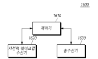
- Fig. 16 is a drawing showing the configuration of a terminal (1600) according to another embodiment.
- a terminal (1600) includes a low-power wake-up receiver (1620), a transceiver (1630), and a controller (1610) that controls the operation of the low-power wake-up receiver and the transceiver.
- the controller (1610) controls the overall operation of the terminal (1600) according to the method of performing wireless communication using a low-power wake-up receiver necessary for performing the present invention described above.
- the controller (1610) can receive configuration information for low power wake-up operations.
- the controller (1610) may receive at least one configuration information that configures parameters used to perform the low-power wake-up operation described in the present disclosure from the base station.
- the configuration information may be received via higher layer signaling, such as RRC signaling.
- the configuration information for the low-power wake-up operation may include configuration information for at least one timer used in the low-power wake-up operation.
- the timer may be set to a duration for monitoring a downlink control channel (PDCCH) via the MR after a wake-up signal is received via the LR.
- the timer may be set to a duration for starting or restarting after a downlink signal, i.e., a wake-up signal or a PDCCH, is received via the LR or MR, and entering the LR mode if no downlink signal is received.
- a downlink signal i.e., a wake-up signal or a PDCCH
- the controller (1610) may monitor a wakeup signal (WUS) through a low-power wakeup receiver based on configuration information.
- the controller (1610) may switch to the LR mode based on the configuration information for the low-power wakeup operation.
- the controller (1610) may monitor whether a wakeup signal is transmitted from the base station through the low-power wakeup receiver corresponding to LR.
- the controller (1610) may switch to the LR mode according to the setting of the corresponding timer.
- the controller (1610) when switched to the LR mode, may monitor a wake-up signal through the low-power wake-up receiver (1620) without performing wireless communication according to MR. Based on the configuration information for the low-power wake-up operation, the controller (1610) may perform monitoring of the wake-up signal until the wake-up signal is received.
- the controller (1610) may perform operations related to radio resource management (RRM) related to the wake-up signal. For example, operations such as receiving and measuring a reference signal related to RRM may be performed.
- RRM radio resource management
- the controller (1610) may start a predetermined timer when a wake-up signal is received.
- the controller (1610) may perform monitoring according to configuration information for a low-power wake-up operation to receive a wake-up signal transmitted from a base station.
- the controller (1610) may start a LR mode transition timer when a wake-up signal is received.
- the LR mode transition timer may be set to a period for monitoring a downlink control channel through MR after a wake-up signal is received through LR.
- the LR mode transition timer may be set to a period for starting or restarting after a wake-up signal or a downlink control channel is received, and entering the LR mode if a downlink signal is not received.
- the timers in the two cases described above may be configured as either one of the timers or may be configured together as separate timers.
- the controller (1610) can monitor the downlink control channel through the transceiver when the timer starts.
- the controller (1610) can turn on the transceiver (1630) corresponding to the MR while the LR mode switching timer is operating to monitor whether the PDCCH is transmitted from the base station.
- the transceiver is not limited to one device, and may be configured with each device corresponding to a transmitter and a receiver.
- monitoring of a wake-up signal and monitoring of a downlink control channel can be performed simultaneously while a timer is running. That is, even if the controller (1610) starts monitoring a PDCCH through a transceiver, it can continue monitoring the wake-up signal through a low-power wake-up receiver.
- the controller (1610) can stop a timer and perform wireless communication through a transceiver when a downlink control channel is received.
- the controller (1610) can stop the LR mode transition timer and turn off the low-power wake-up receiver. That is, when a PDCCH is received, the controller (1610) can stop monitoring for a wake-up signal.
- the NR DRX operation can be performed by starting the DRX inactivity timer. Or, if the terminal is in the RRC Idle state, it can be switched to the connected state through paging reception. After that, data can be transmitted and received with the base station through the transceiver in the MR mode.
- the controller (1610) may stop monitoring the downlink control channel.
- the terminal may turn off the transceiver and continue monitoring the low-power wake-up signal that was being performed. That is, the controller (1610) may perform an operation in the LR mode.
- the controller (1610) may stop monitoring the downlink control channel. That is, even while the LR mode transition timer is running, if a transition instruction to the LR mode is received from the base station, the controller (1610) may turn off the transceiver. Accordingly, the controller (1610) may continue to monitor the low power wake-up signal that it was performing. That is, the controller (1610) may perform an operation in the LR mode.
- the timer may be configured to restart if a wake-up signal or a downlink control channel is received while the timer is in operation.
- the LR mode transition timer may be configured to restart even if other downlink data is received in addition to the wake-up signal or the downlink control channel. If the LR mode transition timer expires without receiving any downlink data, the controller (1610) may transition to the LR mode.
- monitoring of the wake-up signal and the downlink control channel by the terminal may be set to be continuously performed.
- the controller (1610) may restart the LR mode transition timer and turn on the transceiver to monitor the PDCCH. Thereafter, when a wake-up signal is received while the LR mode transition timer is operating, the controller (1610) may restart the LR mode transition timer and continuously perform monitoring of the wake-up signal and the downlink control channel.
- monitoring of a wake-up signal by the terminal may be set to be stopped. That is, when monitoring of a wake-up signal and a downlink control channel is performed simultaneously, when a downlink control channel is received, the controller (1610) may restart the LR mode transition timer. In this case, the controller (1610) may turn off the low-power wake-up receiver and operate in the MR mode. In addition, the controller (1610) may transmit a HARQ feedback message for downlink data to the base station.
- the controller (1610) can transition to the LR mode.
- a method and device for performing wireless communication using a low-power wake-up receiver capable of performing a wake-up operation that consumes power efficiently can be provided.
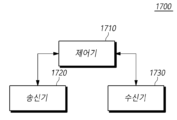
- Fig. 17 is a diagram showing the configuration of a base station (1700) according to another embodiment.
- a base station (1700) includes a transmitter (1720), a receiver (1730), and a controller (1710) that controls the operation of the transmitter and the receiver.
- the controller (1710) controls the overall operation of the base station (1700) according to the method of performing wireless communication using the low-power wake-up receiver required to perform the above-described present invention.
- the transmitter (1720) transmits downlink control information, data, and messages to the terminal through the corresponding channel.
- the receiver (1730) receives uplink control information, data, and messages from the terminal through the corresponding channel.
- the controller (1710) can transmit configuration information for a low-power wake-up operation.
- the controller (1710) can receive at least one configuration information that configures parameters used to perform the low-power wake-up operation described in the present disclosure to the terminal.
- the configuration information can be transmitted via upper layer signaling, such as RRC signaling.
- Configuration information for a low-power wake-up operation may include configuration information for at least one timer used in the low-power wake-up operation.
- the controller (1710) may transmit a wakeup signal (WUS) to the terminal based on the configuration information when downlink data to be transmitted to the terminal is confirmed.
- the controller (1710) may instruct the terminal to switch to the LR mode based on the configuration information for the low-power wakeup operation.
- the controller (1710) may transmit an instruction to switch to the LR mode to the terminal so that the terminal monitors the wakeup signal through a low-power wakeup receiver.
- the controller (1710) may recognize that the terminal has switched to the LR mode based on the setting of the corresponding timer.
- the controller (1710) may transmit a wake-up signal to the terminal if it is necessary to transmit downlink data to the terminal after the terminal has switched to LR mode.
- the controller (1710) can transmit a downlink control channel for transmitting downlink data. If the terminal is in an RRC Connected state, the controller (1710) can perform an NR DRX operation while starting a DRX inactivity timer. Or, if the terminal is in an RRC Idle state, the controller (1710) can switch to a connected state through paging transmission. Thereafter, data can be transmitted and received with the terminal through a transceiver in the MR mode.
- the controller (1710) when it transmits a wake-up signal, it may start a predetermined timer.
- an LR mode transition timer set individually for each terminal or set for each terminal group may be started.
- the LR mode transition timer may be set to a period during which the terminal monitors a downlink control channel via MR after receiving a wake-up signal via LR.
- the controller (1710) can stop the timer and perform wireless communication with the terminal.
- the controller (1710) may retransmit the wake-up signal to the terminal. That is, if the HARQ feedback information is not received while the LR mode transition timer of the base station is operating, the LR mode transition timer expires. Accordingly, the controller (1710) may report that the transmission of the downlink control channel and associated downlink data to the terminal has failed, and may retransmit the wake-up signal in the LR mode.
- the controller (1710) may transmit a low power mode transition instruction to an unintended terminal among the terminal groups to which the wake-up signal is transmitted. That is, if the wake-up signal is transmitted to a terminal group, the controller (1710) may individually transmit a low power mode transition instruction to a terminal that is not intended to be woken up. In this case, the controller (1710) may transmit a wake-up signal in LR mode to the corresponding terminal.
- the controller (1710) can restart the timer and perform wireless communication with the terminal.
- the LR mode transition timer is set to a period for starting or restarting when a downlink signal is transmitted and entering the LR mode if HARQ feedback information is not received.
- the timers in the two cases described above may be configured with only one timer, or may be configured together as separate timers.
- the controller (1710) may transmit downlink data to the terminal in MR mode, and restart the LR mode transition timer whenever HARQ feedback information for the transmitted downlink data is received. Thereafter, when the LR mode transition timer expires, the controller (1710) may transmit a wake-up signal to the terminal in LR mode.
- a method and device for performing wireless communication using a low-power wake-up receiver capable of performing a wake-up operation that consumes power efficiently can be provided.
- the above-described embodiments can be implemented through various means.
- the embodiments can be implemented by hardware, firmware, software, or a combination thereof.
- the method according to the present embodiments can be implemented by one or more ASICs (Application Specific Integrated Circuits), DSPs (Digital Signal Processors), DSPDs (Digital Signal Processing Devices), PLDs (Programmable Logic Devices), FPGAs (Field Programmable Gate Arrays), processors, controllers, microcontrollers, or microprocessors.
- ASICs Application Specific Integrated Circuits
- DSPs Digital Signal Processors
- DSPDs Digital Signal Processing Devices
- PLDs Programmable Logic Devices
- FPGAs Field Programmable Gate Arrays
- processors controllers, microcontrollers, or microprocessors.
- the method according to the present embodiments may be implemented in the form of a device, procedure, or function that performs the functions or operations described above.
- the software code may be stored in a memory unit and may be driven by a processor.
- the memory unit may be located inside or outside the processor and may exchange data with the processor by various means already known.
- system may generally refer to a computer-related entity hardware, a combination of hardware and software, software, or software in execution.
- the aforementioned components may be, but are not limited to, a process driven by a processor, a processor, a controller, a control processor, an object, a thread of execution, a program, and/or a computer.
- an application running on a controller or a processor and the controller or the processor can both be components.
- One or more components may be within a process and/or thread of execution, and the components may be located on a single device (e.g., a system, a computing device, etc.) or distributed across two or more devices.
Landscapes
- Mobile Radio Communication Systems (AREA)
Abstract
Les présents modes de réalisation concernent un procédé pour effectuer une communication sans fil par un terminal à l'aide d'un récepteur de réveil à faible puissance (LR), le procédé comprenant les étapes consistant à : recevoir des informations de configuration sur une opération de réveil à faible puissance; surveiller un signal de réveil (WUS) au moyen d'un récepteur de réveil à faible puissance sur la base des informations de configuration; lorsque le signal de réveil est reçu, démarrer un temporisateur prédéterminé; et surveiller un canal de commande de liaison descendante au moyen d'un émetteur-récepteur lorsque le temporisateur commence.
Applications Claiming Priority (4)
| Application Number | Priority Date | Filing Date | Title |
|---|---|---|---|
| KR20230085354 | 2023-06-30 | ||
| KR10-2023-0085354 | 2023-06-30 | ||
| KR1020240081881A KR20250003321A (ko) | 2023-06-30 | 2024-06-24 | 저전력 웨이크업 수신기를 이용하여 무선 통신을 수행하는 방법 및 장치 |
| KR10-2024-0081881 | 2024-06-24 |
Publications (1)
| Publication Number | Publication Date |
|---|---|
| WO2025005708A1 true WO2025005708A1 (fr) | 2025-01-02 |
Family
ID=93939376
Family Applications (1)
| Application Number | Title | Priority Date | Filing Date |
|---|---|---|---|
| PCT/KR2024/009063 Ceased WO2025005708A1 (fr) | 2023-06-30 | 2024-06-28 | Procédé et dispositif pour effectuer une communication sans fil à l'aide d'un récepteur de réveil à faible puissance |
Country Status (1)
| Country | Link |
|---|---|
| WO (1) | WO2025005708A1 (fr) |
Citations (5)
| Publication number | Priority date | Publication date | Assignee | Title |
|---|---|---|---|---|
| KR20190062318A (ko) * | 2017-11-28 | 2019-06-05 | 한국전자통신연구원 | 무선랜에서 저전력 모드를 지원하는 통신 노드의 동작 방법 |
| KR20210057732A (ko) * | 2018-08-10 | 2021-05-21 | 지티이 코포레이션 | 수신 구성 및 제어 방법, 장치, 단말, 기지국 및 저장매체 |
| KR20210063420A (ko) * | 2018-09-27 | 2021-06-01 | 다탕 모바일 커뮤니케이션즈 이큅먼트 코포레이션 리미티드 | 단말 상태 전환 방법, 네트워크 기기 및 단말 |
| KR20220119192A (ko) * | 2018-08-10 | 2022-08-26 | 다탕 모바일 커뮤니케이션즈 이큅먼트 코포레이션 리미티드 | 신호 송수신 방법, 네트워크 장치 및 단말 |
| KR102503619B1 (ko) * | 2019-02-02 | 2023-02-23 | 비보 모바일 커뮤니케이션 컴퍼니 리미티드 | 에너지 절약 모드의 전환 방법, 에너지 절약 모드의 구성 방법 및 통신 장치 |
-
2024
- 2024-06-28 WO PCT/KR2024/009063 patent/WO2025005708A1/fr not_active Ceased
Patent Citations (5)
| Publication number | Priority date | Publication date | Assignee | Title |
|---|---|---|---|---|
| KR20190062318A (ko) * | 2017-11-28 | 2019-06-05 | 한국전자통신연구원 | 무선랜에서 저전력 모드를 지원하는 통신 노드의 동작 방법 |
| KR20210057732A (ko) * | 2018-08-10 | 2021-05-21 | 지티이 코포레이션 | 수신 구성 및 제어 방법, 장치, 단말, 기지국 및 저장매체 |
| KR20220119192A (ko) * | 2018-08-10 | 2022-08-26 | 다탕 모바일 커뮤니케이션즈 이큅먼트 코포레이션 리미티드 | 신호 송수신 방법, 네트워크 장치 및 단말 |
| KR20210063420A (ko) * | 2018-09-27 | 2021-06-01 | 다탕 모바일 커뮤니케이션즈 이큅먼트 코포레이션 리미티드 | 단말 상태 전환 방법, 네트워크 기기 및 단말 |
| KR102503619B1 (ko) * | 2019-02-02 | 2023-02-23 | 비보 모바일 커뮤니케이션 컴퍼니 리미티드 | 에너지 절약 모드의 전환 방법, 에너지 절약 모드의 구성 방법 및 통신 장치 |
Similar Documents
| Publication | Publication Date | Title |
|---|---|---|
| WO2021086128A1 (fr) | Procédé et appareil d'économie d'énergie d'un équipement d'utilisateur dans un système de communication sans fil | |
| WO2022086109A1 (fr) | Procédé et dispositif de traitement de données de services mbs | |
| WO2020071698A1 (fr) | Procédé pour la réalisation d'une communication à l'aide d'un réseau non terrestre et appareil correspondant | |
| WO2021080240A1 (fr) | Procédé de commande de communication de liaison latérale, et dispositif associé | |
| WO2021206340A1 (fr) | Procédé de commande de communication de liaison latérale, et dispositif associé | |
| WO2021153927A1 (fr) | Procédé de réalisation d'une communication à l'aide de multiples usim et dispositif associé | |
| WO2024005454A1 (fr) | Procédé et dispositif de gestion de faisceau à l'aide de l'intelligence artificielle et de l'apprentissage machine | |
| WO2021002632A1 (fr) | Procédé et dispositif de commande de charge de petites données | |
| WO2019212246A1 (fr) | Procédé et dispositif pour l'exécution d'un positionnement dans un réseau new radio | |
| WO2020091546A1 (fr) | Coordination de configurations pour un fonctionnement à faible consommation d'énergie d'une technologie nr | |
| WO2021145611A1 (fr) | Procédé et dispositif permettant d'effectuer une communication à l'aide de plusieurs usims | |
| WO2020060355A1 (fr) | Procédé et dispositif de réduction de consommation d'énergie pendant la mesure dans un système de communication sans fil | |
| WO2020009498A1 (fr) | Procédé de transmission de données de liaison montante dans une bande sans licence et dispositif associé | |
| WO2022149907A1 (fr) | Procédé de commande de communication de liaison latérale et dispositif associé | |
| WO2020013645A1 (fr) | Procédé et dispositif d'exécution d'une transmission sans fil dans une bande sans licence | |
| WO2021206371A1 (fr) | Procédé de commande de communication de liaison latérale et dispositif associé | |
| WO2024172601A1 (fr) | Procédé et appareil de transmission et de réception de signaux sans fil dans un système de communication sans fil | |
| WO2025014264A1 (fr) | Procédé et dispositif pour effectuer une communication sans fil à l'aide d'un récepteur de réveil à faible puissance | |
| WO2024210667A1 (fr) | Procédé et appareil de transmission et de réception répétées de canal de données de liaison montante dans une communication en duplex intégral | |
| WO2025005708A1 (fr) | Procédé et dispositif pour effectuer une communication sans fil à l'aide d'un récepteur de réveil à faible puissance | |
| WO2025009927A1 (fr) | Procédé et dispositif de communication sans fil utilisant un récepteur de réveil à faible puissance | |
| WO2025034053A1 (fr) | Procédé et dispositif pour effectuer une communication sans fil à l'aide d'un récepteur de réveil à faible puissance | |
| WO2022211584A1 (fr) | Procédé et dispositif pour opération de drx dans un système de communication sans fil | |
| WO2025042131A1 (fr) | Procédé et appareil pour une opération de commutation de mode à l'aide d'un récepteur de faible puissance | |
| WO2022039524A1 (fr) | Procédé et appareil de commande d'une opération de radiomessagerie |
Legal Events
| Date | Code | Title | Description |
|---|---|---|---|
| 121 | Ep: the epo has been informed by wipo that ep was designated in this application |
Ref document number: 24832485 Country of ref document: EP Kind code of ref document: A1 |
|
| NENP | Non-entry into the national phase |
Ref country code: DE |