WO2025009251A1 - Dispositif de distribution de boisson - Google Patents
Dispositif de distribution de boisson Download PDFInfo
- Publication number
- WO2025009251A1 WO2025009251A1 PCT/JP2024/016155 JP2024016155W WO2025009251A1 WO 2025009251 A1 WO2025009251 A1 WO 2025009251A1 JP 2024016155 W JP2024016155 W JP 2024016155W WO 2025009251 A1 WO2025009251 A1 WO 2025009251A1
- Authority
- WO
- WIPO (PCT)
- Prior art keywords
- hot water
- beverage
- air
- section
- unit
- Prior art date
- Legal status (The legal status is an assumption and is not a legal conclusion. Google has not performed a legal analysis and makes no representation as to the accuracy of the status listed.)
- Ceased
Links
Images











Classifications
-
- A—HUMAN NECESSITIES
- A47—FURNITURE; DOMESTIC ARTICLES OR APPLIANCES; COFFEE MILLS; SPICE MILLS; SUCTION CLEANERS IN GENERAL
- A47J—KITCHEN EQUIPMENT; COFFEE MILLS; SPICE MILLS; APPARATUS FOR MAKING BEVERAGES
- A47J31/00—Apparatus for making beverages
- A47J31/40—Beverage-making apparatus with dispensing means for adding a measured quantity of ingredients, e.g. coffee, water, sugar, cocoa, milk, tea
-
- B—PERFORMING OPERATIONS; TRANSPORTING
- B67—OPENING, CLOSING OR CLEANING BOTTLES, JARS OR SIMILAR CONTAINERS; LIQUID HANDLING
- B67D—DISPENSING, DELIVERING OR TRANSFERRING LIQUIDS, NOT OTHERWISE PROVIDED FOR
- B67D1/00—Apparatus or devices for dispensing beverages on draught
- B67D1/07—Cleaning beverage-dispensing apparatus
-
- B—PERFORMING OPERATIONS; TRANSPORTING
- B67—OPENING, CLOSING OR CLEANING BOTTLES, JARS OR SIMILAR CONTAINERS; LIQUID HANDLING
- B67D—DISPENSING, DELIVERING OR TRANSFERRING LIQUIDS, NOT OTHERWISE PROVIDED FOR
- B67D1/00—Apparatus or devices for dispensing beverages on draught
- B67D1/08—Details
Definitions
- the present invention relates to a beverage supply device.
- beverage supply devices that, when a beverage is selected by a user, produce a beverage in a beverage preparation unit and dispense the beverage into a cup.
- Such beverage supply devices are provided with an ingredient box that contains and stores ingredients such as coffee beans, and the ingredient box dispenses the amount of ingredients required to produce the beverage to the beverage preparation unit when driven by a built-in ingredient supply drive unit.
- ingredient boxes protrude above the top plate of the device main body, part of which is the housing, and the inside can be seen (see, for example, Patent Document 1).
- the ingredient box in the beverage supply device described above had a dispensing section that contained a raw material supply drive section and dispensed ingredients to the beverage production section when driven by the raw material supply drive section, and a storage section that engaged with the dispensing section in such a way that its communication port communicated with the inlet of the dispensing section.
- This storage section was freely engageable and detachable with respect to the dispensing section, and its operating section was exposed from the device body.
- the storage unit can be detached from the dispensing unit, making it easy to clean the storage unit; however, because the operating unit is exposed from the device body, there is a risk that the operating unit could be operated by an unintended person, causing the storage unit to detach from the dispensing unit and extracting ingredients such as coffee beans.
- the present invention aims to provide a beverage supply device that can prevent ingredients from being extracted while making it easy to clean the ingredient box.
- the beverage supply device of the present invention is a beverage supply device that includes an ingredient box that contains and stores ingredients and dispenses the ingredients to a beverage production section by driving a built-in ingredient supply drive section, and supplies a beverage produced by the beverage production section to a cup
- the ingredient box includes a dispensing section that incorporates the ingredient supply drive section and dispenses ingredients to the beverage production section by driving the ingredient supply drive section, and a storage section that is arranged in a manner that a part of it is exposed from the device main body, which is a housing, by engaging with the dispensing section in a manner that its communication port communicates with the inlet of the dispensing section, and is provided so as to be engageable and detachable with the dispensing section, and an operating section for engaging and detaching the storage section with the dispensing section is disposed inside the device main body.
- the present invention is also characterized in that in the beverage supply device, the device main body comprises a main body cabinet having an opening on the front side, and a front door provided on the main body cabinet in a manner that opens and closes the opening, and the operating unit is disposed inside the main body cabinet in the front portion of the ingredient box.
- the present invention is also characterized in that, in the beverage supply device, the operating unit is disposed in the dispensing unit, and when an operating force is applied to the operating unit, it disengages from the storage unit, allowing the storage unit to separate from the dispensing unit.
- the present invention is also characterized in that in the beverage supply device, the storage section can be detached from the dispensing section by sliding in the forward and backward directions relative to the dispensing section.
- the ingredient box includes a dispensing section that incorporates an ingredient supply drive section and dispenses ingredients to the beverage production section by driving the ingredient supply drive section, and a storage section that is arranged in a manner that a part of it is exposed from the device main body, which is the housing, by engaging with the dispensing section in a manner that its own communication port communicates with the inlet of the dispensing section, and is provided so as to be engageable and detachable with the dispensing section, and an operating section for engaging and detaching the storage section with the dispensing section is disposed inside the device main body, thus achieving the effect of preventing ingredients from being extracted while facilitating cleaning of the ingredient box.
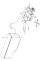
- FIG. 1 is a perspective view showing the external configuration of a beverage supplying device according to an embodiment of the present invention.
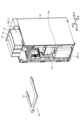
- FIG. 2 is a perspective view showing the internal structure of the beverage supply device according to the embodiment of the present invention.
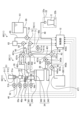
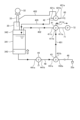
- FIG. 3 is a schematic diagram showing main components of the beverage supply device according to the embodiment of the present invention.
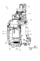
- FIG. 4 is a perspective view showing the internal structure of the beverage supply device according to the embodiment of the present invention, with some components not shown.
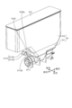
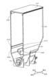
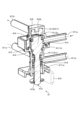
- FIG. 5 is a perspective view showing one raw material box.
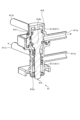
- FIG. 6 is a perspective view showing one raw material box.
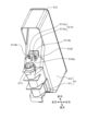
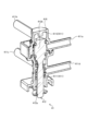
- FIG. 7 is an exploded perspective view showing one raw material box.
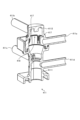
- FIG. 8 is an exploded perspective view showing one raw material box.
- FIG. 9 is a side view showing the state in which the storage unit shown in FIGS.
- FIG. 10 is a cross-sectional view showing the internal structure of the raw material box shown in FIGS.
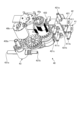
- FIG. 11 is a perspective view showing the external configuration of the extractor shown in FIGS.
- FIG. 12 is a vertical cross-sectional view of a main portion of the extractor shown in FIG. 13(a) and (b) are vertical cross-sectional views of the passage forming member.
- FIG. 14 is a cross-sectional view showing a main part of the extractor shown in FIG.
- FIG. 15 is a perspective view showing the valve group shown in FIG.
- FIG. 16 is a cross-sectional view showing the internal structure of the air valve shown in FIG. 3 or FIG. FIG.
- FIG. 17 is a cross-sectional view showing the internal structure of the air valve shown in FIG. 3 or FIG.
- FIG. 18 is a cross-sectional view showing the internal structure of the air valve shown in FIG. 3 or FIG.
- FIG. 19 is a cross-sectional view showing the internal structure of the air valve case shown in FIGS.
- FIG. 20 is a perspective view showing the external configuration of the hot water valve shown in FIG. 3 and
- FIG. 21 is a cross-sectional view showing the internal structure of the hot water valve shown in FIG. 3 or FIG.
- FIG. 22 is a cross-sectional view showing the internal structure of the hot water valve shown in FIG. 3 or FIG.
- FIG. 23 is a perspective view showing the external configuration of the hot water valve shown in FIG. 3 and FIG. FIG.
- FIG. 24 is a cross-sectional view showing the internal structure of the hot water valve case shown in FIGS.
- FIG. 25 is an exploded perspective view of the coffee valve shown in FIG. 3 or FIG. 15.
- FIG. 26 is a perspective view showing the external configuration of the drainage valve shown in FIG. 27 is an exploded perspective view of the drainage valve shown in FIG. 3.
- FIG. 28 is an explanatory diagram showing a schematic diagram of a procedure for extracting a beverage using the extractor shown in FIG.
- FIG. 29 is an explanatory diagram showing a schematic diagram of a procedure for extracting a beverage using the extractor shown in FIG.
- FIG. 30 is an explanatory diagram showing a schematic diagram of a procedure for extracting a beverage using the extractor shown in FIG. FIG.
- FIG. 31 is an explanatory diagram showing a schematic diagram of a procedure for extracting a beverage using the extractor shown in FIG.
- FIG. 32 is an explanatory diagram showing a schematic diagram of a procedure for extracting a beverage using the extractor shown in FIG.
- FIG. 33 is an explanatory diagram showing a schematic diagram of a procedure for extracting a beverage using the extractor shown in FIG.
- FIG. 34 is an explanatory diagram showing a schematic diagram of cleaning of the mixing air line and the extraction air line by the extractor shown in FIG.
- Figures 1 to 4 each show a beverage supply device that is an embodiment of the present invention, where Figure 1 is an oblique view showing the external configuration of the beverage supply device, Figure 2 is an oblique view showing the internal structure of the beverage supply device, Figure 3 is a schematic diagram showing the main components of the beverage supply device, and Figure 4 is an oblique view showing the internal structure of the beverage supply device, with some components not shown.
- the beverage supply device 1 illustrated here is a coffee machine installed in a store such as a convenience store, and supplies beverages such as coffee to a container, such as a cup C, by, for example, grinding beans and carrying out extraction processes.
- a beverage supply device 1 is configured with a main cabinet 10 and a front door 20.
- the main cabinet 10 is the device main body in the shape of a roughly rectangular parallelepiped with a front opening 10a (see FIG. 4) on the front side, and contains a beverage (e.g., coffee) making unit 11 and a control unit 12 inside.
- a beverage e.g., coffee
- the front door 20 is a door body large enough to close the front opening 10a of the main cabinet 10.
- This front door 20 is provided on the left edge of the front side of the main cabinet 10 so as to be able to swing around the central axis of an axis part (not shown) that extends in the vertical direction, and is capable of opening and closing the front opening 10a of the main cabinet 10.
- the front side of this front door 20 constitutes the customer service surface, and is provided with a display unit 21, a beverage supply unit 22, and an opening and closing door 23.
- the display unit 21 is configured, for example, with a liquid crystal touch panel, and displays various information in response to commands given by the control unit 12, and is capable of performing input operations such as touch operations. When an input operation such as a touch operation is performed, the display unit 21 sends a sales signal to the control unit 12.
- the beverage supply unit 22 is provided below the display unit 21 and has a nozzle 22a and a stage 22b.
- the nozzle 22a ejects the beverage produced in the production unit 11 downward.
- the stage 22b is provided below the nozzle 22a.
- the stage 22b is used to place the cup C on.
- the opening/closing door 23 is made of a translucent material such as a transparent resin, and is large enough to cover the entrance 22c of the beverage supply unit 22.
- the left end of this opening/closing door 23 is pivoted to the front door 20, and it can swing in the front-to-rear direction.
- the opening/closing door 23 can swing in the front-to-rear direction in a manner that moves toward and away from the beverage supply unit 22, and can close the entrance 22c of the beverage supply unit 22 when it swings backward in a manner that moves toward the beverage supply unit 22, and can open the entrance 22c of the beverage supply unit 22 when it swings forward in a manner that moves away from the beverage supply unit 22.
- the production unit 11 is comprised of an extractor (beverage production section) 30, an ingredient supply section 50, a hot water supply section 60, an air supply section 70, and a storage bucket 80.
- the extractor 30 extracts coffee, a beverage, from ingredients supplied from the ingredient supply unit 50 and hot water supplied from the hot water supply unit 60, and supplies it to the beverage supply unit 22.
- the raw material supply unit 50 supplies coffee beans, which are a beverage raw material, to the extraction machine 30, and is equipped with a raw material box 51.
- the raw material box 51 contains roasted coffee beans, and is provided in such a way that a portion of it protrudes upward from the top plate portion 13 of the main body cabinet 10.
- This raw material box 51 is provided with a raw material supply drive unit 51a.
- the raw material supply drive unit 51a drives the raw material supply motor 51b, which is the drive source, when a drive command is given from the control unit 12, and dispenses a predetermined amount of coffee beans included in the drive command through the raw material supply chute 52.
- the hot water supply unit 60 supplies hot water to the extraction machine 30, and is configured by sequentially connecting a hot water tank 61, a first hot water supply pump 62, a sub-tank 63, and a second hot water supply pump 64 to a hot water supply path 65 formed by hot water supply piping.
- the hot water tank 61 heats supplied water, such as tap water, with a heater (not shown) and stores it as hot water.
- the first hot water supply pump 62 is composed of, for example, a centrifugal pump, and when driven by a command given from the control unit 12, it sends out a fixed amount of hot water from the hot water tank 61 to the subtank 63.
- the subtank 63 has a smaller volume than the hot water tank 61, and temporarily stores the hot water sent out by the first hot water supply pump 62.
- the second hot water supply pump 64 is composed of, for example, a gear pump, and when driven by a command given from the control unit 12, it sends out hot water from the subtank 63.
- the air supply unit 70 supplies pressurized air to the extractor 30.
- This air supply unit 70 is configured by providing an air pump 72 in an air supply path 71 formed by air supply piping.
- the air pump 72 is driven in response to a command given by the control unit 12, and compresses air and sends it out as pressurized air.
- the collection bucket 80 is installed below the extractor 30 and is used to collect the extraction grounds K (see Figure 32, etc.) that are generated when the beverage is extracted by the extractor 30.
- the control unit 12 comprehensively controls the operation of each part of the beverage supply device 1 in accordance with programs and data stored in a memory unit (not shown).
- the control unit 12 may be realized, for example, by having a processing device such as a CPU (Central Processing Unit) execute a program, i.e., by software, or may be realized by hardware such as an IC (Integrated Circuit), or may be realized by a combination of software and hardware.
- a processing device such as a CPU (Central Processing Unit) execute a program, i.e., by software, or may be realized by hardware such as an IC (Integrated Circuit), or may be realized by a combination of software and hardware.
- IC Integrated Circuit
- a plurality of raw material boxes 51 (three in the illustrated example) are provided, and are arranged side by side with other raw material boxes 51.
- Each of the raw material boxes 51 is installed in a manner that it penetrates a top plate hole 13a formed in the top plate portion 13 of the main body cabinet 10.
- each of the raw material boxes 51 is arranged in a manner that a part of each of the raw material boxes 51 is exposed from the main body cabinet 10, which is a housing.
- the raw material boxes 51 may contain different types of raw materials, or may contain multiple raw materials of the same type and some different types of raw materials. Since each of these raw material boxes 51 has the same configuration, the following describes the configuration of one raw material box 51 and omits descriptions of the configurations of the other raw material boxes 51.
- Figures 5 to 8 each show one raw material box 51, with Figures 5 and 6 being perspective views and Figures 7 and 8 being exploded perspective views. As shown in Figures 5 to 8, the raw material box 51 is configured with a dispensing section 511 and a storage section 512.
- the dispensing unit 511 is installed inside the main cabinet 10, i.e., below the top plate 13 of the main cabinet 10, and is a box in which the above-mentioned raw material supply drive unit 51a is disposed.
- the dispensing unit 511 is formed with a dispensing outlet 5111, an inlet 5112, a locking protrusion 5113, an insertion opening 5114, and an operation unit 5115.
- the outlet 5111 is provided at the lower front part of the dispensing section 511 and is an opening for dispensing raw materials to the extractor 30 when the raw material supply drive section 51a is driven.
- the inlet 5112 is an opening formed at the top of the dispensing section 511.
- the locking protrusions 5113 are provided three on each side in the front-to-rear direction on the inside of the left and right opening edges of the inlet 5112. These locking protrusions 5113 are spaced apart in the front-to-rear direction and are formed to protrude inward of the inlet 5112.
- the insertion opening 5114 is formed on the opening edge on the rear side of the inlet 5112 and has an elongated hole shape with the left-to-right direction as the longitudinal direction.
- the operating section 5115 is composed of a pair of left and right protrusions 5115a formed on the upper front portion of the dispensing section 511 in a manner that protrudes forward.
- This operating section 5115 is formed with a locking protrusion 5115b that protrudes outward. That is, the left protrusion 5115a is formed with a locking protrusion 5115b that protrudes to the left, and the right protrusion 5115a is formed with a locking protrusion 5115b that protrudes to the right.
- the storage section 512 is made of, for example, a translucent material, so that the inside can be seen.
- This storage section 512 has an inlet 5121 formed at the top and a communication port 5122 formed at the bottom, and the cross-sectional area gradually decreases from the inlet 5121 to the communication port 5122.
- the inlet 5121 is an opening for inputting raw materials, and is opened and closed by the lid 513.
- This inlet 5121 is normally closed by the lid 513.
- the communication port 5122 has approximately the same opening area as the inlet 5112 of the discharge section 511.
- an insertion piece 5123 In such a storage section 512, an insertion piece 5123, a locking projection 5124, and a locking block 5125 are formed.
- the insertion piece 5123 is a flat plate formed in such a manner that it protrudes rearward from the rear opening edge of the communication opening 5122. This insertion piece 5123 has a size that allows it to enter the insertion opening 5114.
- the engaging projections 5124 are formed so as to protrude outward on the outside of the left and right opening edges of the communication opening 5122.
- the engaging projections 5124 are elongated and extend in the front-to-rear direction, and a notch is formed midway through the projections to allow the engaging projections 5113 to pass through.
- the locked block 5125 is formed in the lower front part of the storage section 512.
- This locked block 5125 is formed with an entry recess 5125a that is open to the front, rear, and downward. This entry recess 5125a allows the entry of the operating section 5115.
- such a storage section 512 approaches the dispensing section 511 from the front side, and with the engaging protrusion 5124 positioned below the engaging protrusion 5113, the insertion piece 5123 is inserted into the insertion opening 5114 from the front, and the operating section 5115 relatively enters the entry recess 5125a of the engaging block 5125 from the rear side, so that the engaging protrusion 5115b engages with the front end surface of the entry recess 5125a, thereby engaging with the dispensing section 511 as shown in FIG. 5 and FIG. 6 to form the raw material box 51.
- the storage section 512 is restricted from moving rearward relative to the dispensing section 511 by inserting the insertion piece 5123 into the insertion opening 5114 from the front. Also, as shown in FIG. 10, the storage section 512 is restricted from moving upward relative to the dispensing section 511 by engaging the locking protrusion 5124 with the locking protrusion 5113 engaged with the locking protrusion 5113 while positioned below the locking protrusion. Furthermore, the storage section 512 is restricted from moving forward relative to the dispensing section 511 by engaging the locking protrusion 5115b of the operation section 5115 with the front end face of the locking block 5125.
- the storage section 512 engages with the dispensing section 511 to form the ingredient box 51, and a portion of the storage section 512 is positioned in a state of protruding upward from the top plate section 13 of the main body cabinet 10 through the top plate hole 13a of the top plate section 13.
- the lid 513 can then be removed to open the inlet 5121, allowing ingredients such as coffee beans to be filled into the ingredient box 51.
- the ingredient supply drive section 51a is then driven in response to a command given from the control section 12, allowing the ingredient box 51 to dispense a predetermined amount of ingredient from the dispensing opening 5111 to the extraction machine 30.
- the storage section 512 can be removed from the dispensing section 511 as follows. First, as shown in FIG. 4, the front door 20 is opened, and then a portion of the top plate 13 is removed forward. Next, the pair of left and right protrusions 5115a of the operating section 5115 are elastically deformed so that they approach each other, thereby releasing the engagement between the locking protrusion 5115b and the locked block 5125, and displacing the storage section 512 forward relative to the dispensing section 511. This causes the insertion piece 5123 to move away from the insertion opening 5114, and the locked protrusion 5124 to displace the lower part of the locking protrusion 5113 forward, allowing the storage section 512 to be detached from the dispensing section 511.
- the raw material box 51 has a storage section 512 that can be freely engaged and disengaged with the dispensing section 511, and the dispensing section 511 is disposed below the top plate section 13 of the main body cabinet 10, and the operation section 5115 is formed in the dispensing section 511, so that the operation section 5115 is disposed inside the main body cabinet 10.
- Fig. 11 is a perspective view showing the external configuration of the extractor 30 shown in Fig. 3 and Fig. 4.
- the extractor 30 includes an extractor main body 31, in which a crusher 32, a brewer unit 34, a pinch mechanism 36, a scraper 38, and a valve group 40 are provided.
- the crusher 32 is what is commonly called a mill, and is provided on the top of the extractor body 31. This crusher 32 is driven when a drive command is given to the crusher drive unit 32a, which is an actuator. This crusher 32 is installed below the raw material box 51, and is connected to the raw material box 51 via the raw material supply chute 52.
- the grinder 32 When the grinder 32 is driven, it grinds the coffee beans guided by the raw material supply chute 52 and feeds the ground coffee beans (hereinafter also referred to as ground coffee beans) into the brewer unit 34 through the raw material chute section 33.
- the raw material chute section 33 has a raw material passage 331 for dropping the ground coffee beans. The raw material chute section 33 will be described later.
- the brewer unit 34 is comprised of a cylinder 341, a top seal portion 342, and a filter block 343.
- the cylinder 341 is removably attached through the removal opening 311 on the front of the extractor body 31, and has a generally cylindrical shape. Because the cylinder 341 is detachable from the extractor body 31, its orientation is not clearly defined, but in this specification, its configuration will be described according to the orientation when attached to the extractor body 31.
- the cylinder 341 has an opening 341a on the bottom surface (hereinafter also referred to as the bottom opening) and an opening 341b on the top surface (hereinafter also referred to as the top opening).
- a cylinder 341 is mounted in a mounting area 312 facing the removal opening 311 in the extractor body 31, and when mounted in the extractor body 31, it is pressed upward by the removal door 313 that opens and closes the removal opening 311 shown in FIG. 4.
- the removal door 313 closes a part of the removal opening 311, the cylinder 341 is pressed upward.
- the removal door 313 swings forward, the cylinder 341 becomes free and can be removed from the mounting area 312.
- the top seal portion 342 is provided on the extractor body 31 in such a manner that it constitutes the upper portion of the mounting area 312. This top seal portion 342 is pressed against the cylinder 341 when the cylinder 341 is pressed upward by the removal door 313, and closes the top opening 341b of the cylinder 341.
- such a top seal portion 342 is formed with a cylindrical passageway component 35 that extends upward and communicates with the top opening 341b.
- This passageway component 35 is made of a resin material such as silicone, and has an elliptical cross section. A part of the ingredient chute section 33 is inserted from above into the hollow portion of such passageway component 35, and the hollow portion forms a passageway 351 through which ground coffee beans and mixed water (hot water) pass, as will be described in detail later, and its inner wall surface is water repellent.
- a part of the upper end portion of the hollow part of the passage forming member 35 is connected to the exhaust duct 49 in a manner that is partitioned from the raw material chute section 33.
- the exhaust duct 49 not only communicates with the passage forming member 35, but also communicates with the inside of the cylinder 341 via the passage forming member 35 when the cylinder 341 is mounted in the mounting area 312.
- Such an exhaust duct 49 is provided with an exhaust fan 46 as shown in FIG. 3.
- This exhaust fan 46 is driven by an exhaust fan drive section 46a, which is an actuator, in response to a command given from the control section 12, and when driven, exhausts the air inside the cylinder 341 to the outside through the exhaust duct 49.
- the filter block 343 is generally box-shaped and movable in the vertical direction below the mounting area 312, with its upper surface being large enough to close the lower opening 341a of the cylinder 341.
- This filter block 343 is provided with a disk-shaped metallic mesh member 343a with multiple holes formed therein, and is connected to a beverage supply path 48 that communicates with these holes.
- This beverage supply path 48 is configured by connecting a beverage supply pipe, and connects the filter block 343 with the nozzle 22a.
- This filter block 343 moves in the vertical direction when the filter block drive unit 343b, which is an actuator, is driven in response to a command given by the control unit 12. In other words, it moves up and down while moving toward and away from the cylinder 341 mounted in the mounting area 312. When the filter block 343 moves up, it presses against the bottom opening 341a of the cylinder 341 to close it.
- the pinch mechanism 36 is provided above the top seal portion 342.
- This pinch mechanism 36 is configured with a first pinch component 361 and a second pinch component 362 that extend in the left-right direction and are spaced apart from each other in the front-rear direction, and a passage component 35 is disposed between the first pinch component 361 and the second pinch component 362.
- the pinch mechanism 36 In the normal state, the first pinch component 361 and the second pinch component 362 are disposed at the furthest distance from each other, and the pinch mechanism 36 has no effect on the passage component 35, as shown in FIG. 13(a).
- the pinch mechanism 36 elastically deforms the lower part of the passage component 35 to close a part of the passage 351, as shown in FIG. 13(b).
- the part where the pinch mechanism 36 clamps the passage component 35 to close a part of the passage 351 is the lower part of the passage component 35, i.e., the part below the area where the raw material chute section 33 is inserted.
- the scraper 38 is a flat plate-shaped member that extends in the vertical direction, and the lower end portion 38a is made of a resin material such as rubber.
- the upper end portion 38b of the scraper 38 is also made of a flexible soft material. Such a scraper 38 is connected to the scraper body 381.
- the scraper 38 moves in the forward and backward directions when the scraper drive mechanism 382, which is an actuator, is driven by commands given from the control unit 12, transmitting power to the scraper body 381.
- the scraper 38 is installed so that it can move forward and backward in the front-to-rear direction between a standby position that is rearward of the filter block 343 and an advanced position that is forward of the filter block 343, and is normally positioned in the standby position as shown in Figure 14.
- driving equipment 383 such as a scraper drive mechanism 382 is housed on the rear side of the filter block 343, and the standby position is a position close to the driving equipment 383, and the advanced position is a position away from the driving equipment 383.
- the lower end portion 38a can slide against the upper surface of the mesh member 343a of the filter block 343 that has moved to the lowest position, and removes the extraction residue K placed on the mesh member 343a when advancing from the standby position to the advanced position.
- the vertical dimension of such a scraper 38 is slightly smaller than the distance between the cylinder 341 and the filter block 343 that has moved to the lowest position.
- the scraper 38 has a vertical dimension such that the upper end portion 38b comes close to the bottom opening 341a of the cylinder 341 when moving back and forth between the standby position and the advanced position.
- the valve group 40 is installed at the upper rear side of the extraction machine body 31 as shown in FIG. 11, and is configured with an air valve (switching valve) 41, a hot water valve (switching valve) 42, and a coffee valve (valve) 43 as also shown in FIG. 15.
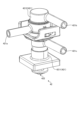
- FIGS. 16 to 18 are cross-sectional views showing the internal structure of the air valve 41 shown in FIG. 3 and FIG. 15, respectively.
- the air valve 41 is configured with an air valve case 411 and an air valve shaft 412.
- the air valve case 411 is formed by connecting a first air valve case component 4111 and a second air valve case component 4112.
- the first air valve case component 4111 is formed in a substantially cylindrical shape.
- the second air valve case component 4112 is formed in a substantially bottomed cylindrical shape with a closed tip, and the internal hollow portion 4111a is connected to the hollow portion 4111a of the first air valve case component 4111.
- the inner diameter of the hollow portion 4112a of the second air valve case component 4112 is larger than the inner diameter of the hollow portion 4111a of the first air valve case component 4111.
- first air valve case component 4111 is formed in a tapered shape in which the inner diameter of the boundary portion 4111b with the second air valve case component 4112 gradually decreases as it moves away from the second air valve case component 4112.
- the first air valve case component 4111 and the second air valve case component 4112 are connected via an O-ring 413 at a location that is not exposed to the hollow portions 4111a and 4112a, thereby maintaining airtightness between the hollow portions 4111a and 4112a.
- Such an air valve case 411 has multiple (four) ports: an air inlet port 411a, an agitation air discharge port 411b, an extraction air discharge port 411c, and an opening port 411d. These ports are connected to the hollow portions 4111a and 4112a, respectively.
- the air inlet port 411a is formed in the second air valve case component 4112 and is connected to the air supply path 71 of the air supply unit 70.
- the stirring air discharge port 411b is formed in the second air valve case component 4112 and is connected to the stirring air line 401.
- This stirring air line 401 is composed of a stirring air supply pipe and is connected to the coffee valve 43.
- the extraction air discharge port 411c is formed in the first air valve case component 4111 and is connected to the extraction air line 402.
- This extraction air line 402 is composed of an extraction air supply pipe and is connected to the top seal portion 342.
- the release port 411d is formed in the first air valve case component 4111 and is an opening for opening the inside of the hollow portion 4111a.
- the air valve shaft 412 is disposed in the hollow portions 4111a and 4112a of the air valve case 411 so as to be displaceable along the axial direction of the air valve case 411.
- the air valve shaft 412 is configured to have a small diameter portion 412a and a large diameter portion 412b with different outer shapes, and is provided with a number of O-rings (annular sealing material) 414.
- the small diameter portion 412a has a maximum diameter that is smaller than the inner diameter of the hollow portion 4111a of the first air valve case component 4111
- the large diameter portion 412b has an outer diameter that is larger than the inner diameter of the hollow portion 4111a of the first air valve case component 4111 and smaller than the inner diameter of the hollow portion 4112a of the second air valve case component 4112.
- Such an air valve shaft 412 is positioned at a reference position by the biasing force of the air valve shaft spring 415, which is a biasing means.
- the air valve shaft spring 415 which is a biasing means.
- one end of the small diameter portion 412a protrudes outward from the air valve case 411, and a part of the large diameter portion 412b contacts the boundary portion 4111b between the first air valve case component 4111 and the second air valve case component 4112.
- the air valve shaft 412 of the air valve 41 can also be positioned at an intermediate position between the reference position and the tip position, as shown in FIG. 18.
- the air inlet port 411a, the stirring air discharge port 411b, the extraction air discharge port 411c, and the release port 411d are all in communication.
- the tip portion 416 of the air valve shaft 412 i.e., the tip portion 416 of the large diameter portion, is umbrella-shaped with a cross-sectional area that gradually decreases toward the tip. Also, in the air valve 41, as shown in FIG. 19, a support rib 417 that can slide against an O-ring 414 provided on the tip side of the air valve shaft 412 is formed on the inner surface of the second air valve case component 4112.
- Such a support rib 417 extends along the axial direction of the air valve case 411 and is formed along the circumferential direction of the air valve case 411, but a notch 418 is formed in the portion close to the air inlet port 411a, i.e., the portion separated from the tip of the air valve case 411.
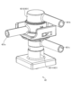
- Figures 20 to 23 show the hot water valve 42 shown in Figures 3 and 15, respectively.
- Figure 20 is an oblique view showing the external configuration of the hot water valve 42
- Figure 21 is a cross-sectional view showing the internal structure of the hot water valve 42
- Figure 22 is a cross-sectional view showing the internal structure of the hot water valve 42
- Figure 23 is an oblique view showing the external configuration of the hot water valve 42.
- the hot water valve 42 is configured with a hot water valve case 421 and a hot water valve shaft 422.
- the hot water valve case 421 is formed by connecting a first hot water valve case component 4211 and a second hot water valve case component 4212.
- the first hot water valve case component 4211 is approximately cylindrical in shape.
- the second hot water valve case component 4212 is approximately cylindrical with a closed end, and the internal hollow portion 4212a is connected to the hollow portion 4211a of the first hot water valve case component 4211.
- the inner diameter of the hollow portion 4212a of the second hot water valve case component 4212 is larger than the inner diameter of the hollow portion 4211a of the first hot water valve case component 4211.
- first hot water valve case component 4211 is formed in a tapered shape in which the inner diameter of the boundary portion 4211b with the second hot water valve case component 4212 gradually decreases as it moves away from the second hot water valve case component 4212.
- the first hot water valve case component 4211 and the second hot water valve case component 4212 are connected via an O-ring 423 at a location that is not exposed to the hollow portions 4211a and 4212a, thereby maintaining airtightness between the hollow portions 4211a and 4112a.
- Such a hot water valve case 421 has multiple (three) ports: a hot water inlet port 421a, a mixed hot water outlet port 421b, and an added hot water outlet port 421c. These ports are connected to the hollow portions 4211a and 4112a, respectively.
- the hot water inlet port 421a is connected to the hot water supply path 65 of the hot water supply section 60.
- the mixed hot water discharge port 421b is connected to the mixed hot water supply path 403.
- This mixed hot water supply path 403 is composed of mixed hot water supply piping, and is connected to the mixed hot water nozzle 404 formed in the raw material chute section 33 as shown in FIG. 12.
- the mixed water nozzle 404 is provided in a manner that faces the raw material passage 331 in the raw material chute section 33, and ejects the mixed water in a fan shape diagonally downward.
- the mixed water nozzle 404 ejects the mixed water in a manner that blocks a part of the raw material passage 331 in the raw material chute section 33.
- the extractor 30 mixes the ground coffee beans and mixed water in the air in the raw material chute section 33, and the mixture is collided with the inner wall surface of the raw material passage 331 and then falls downward along said inner wall surface, without coming into contact with the inner wall surface of the passage component 35.
- the extractor 30 has an intake port 45 for sucking in air above the point where the ground coffee beans are discharged from the grinder 32 into the raw material chute section 33.
- the added hot water discharge port 421c is connected to the added hot water supply path 405.
- This added hot water supply path 405 is composed of an added hot water supply pipe, and is connected to an added hot water nozzle (not shown) formed in the top seal portion 342.
- the added hot water nozzle discharges the added hot water supplied through the added hot water supply path 405 downward in a shower-like manner.
- the hot water valve shaft 422 is disposed in the hollow portions 4211a and 4212a of the hot water valve case 421 so as to be displaceable along the axial direction of the hot water valve case 421.
- the hot water valve shaft 422 is configured with a small diameter portion 422a and a large diameter portion 422b that have different external shapes, and is provided with multiple O-rings (annular sealing material) 424.
- the small diameter portion 422a has a maximum diameter that is smaller than the inner diameter of the hollow portion 4211a of the first hot water valve case component 4211
- the large diameter portion 422b has an outer diameter that is larger than the inner diameter of the hollow portion 4211a of the first hot water valve case component 4211 and smaller than the inner diameter of the hollow portion 4212a of the second hot water valve case component 4212.
- Such a hot water valve shaft 422 is positioned at a reference position by the biasing force of the hot water valve shaft spring 425, which is a biasing means.
- the hot water valve shaft spring 425 which is a biasing means.
- one end of the small diameter portion 422a protrudes outward from the hot water valve case 421, and a part of the large diameter portion 422b contacts the boundary portion 4211b between the first hot water valve case component 4211 and the second hot water valve case component 4212.
- the tip portion 426 of the hot water valve shaft 422 i.e., the tip portion 426 of the large diameter portion, is umbrella-shaped with a cross-sectional area that gradually decreases toward the tip. Also, in the hot water valve 42, as shown in FIG. 24, a support rib 427 that can slide against an O-ring 424 provided on the tip side of the hot water valve shaft 422 is formed on the inner surface of the second hot water valve case component 4212.
- Such a support rib 427 extends along the axial direction of the hot water valve case 421 and is formed along the circumferential direction of the hot water valve case 421, but a notch 428 is formed in the portion close to the hot water introduction port 421a, i.e., the portion separated from the tip of the hot water valve case 421.
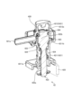
- the coffee valve 43 is disposed midway along the beverage supply path 48. As shown in FIG. 25, the coffee valve 43 is configured by inserting an inner member 432 into a hollow portion 431f of a bottomed cylindrical outer member 431.
- the outer member 431 is formed with a coffee introduction port 431a and a stirring air introduction port 431b.
- the opening (first opening) 4311 constituting the coffee introduction port 431a and the opening (second opening) (not shown) constituting the air introduction port 411a face each other, and the opening 4311 constituting the coffee introduction port 431a is formed with a guide rib 431c that divides it into upper and lower parts.
- the inner member 432 has a coffee discharge port 432a formed therein, and an inlet portion 432b that communicates with the coffee discharge port 432a is formed at the bottom.
- An O-ring (annular sealing material) 433 is disposed at the bottom of the inner member 432 in a manner that surrounds the inlet portion 432b, and a notch portion 432c is formed in the area excluding the inlet portion 432b.
- the coffee inlet port 431a is connected to the filter block 343 (brewer unit 34) through a portion of the beverage supply path 48.
- the stirring air inlet port 431b is connected to the stirring air line 401.
- the coffee discharge port 432a is connected to the nozzle 22a of the beverage supply section 22 through a portion of the beverage supply path 48.
- the coffee introduction port 431a and the coffee discharge port 432a communicate with each other.
- the cutout portion 432c faces the opening 4311 of the coffee introduction port 431a and the opening of the stirring air introduction port 431b, thereby connecting the stirring air introduction port 431b and the coffee introduction port 431a.
- such a valve group 40 includes an air valve 41, hot water valve 42, and coffee valve 43 that are linked by a common valve actuator 40a.
- the valve actuator 40a is configured so that the communication state of each port of the air valve 41, hot water valve 42, and coffee valve 43 is switched by the rotation of cams and gears caused by the drive of a valve motor 40b that constitutes the valve actuator 40a.
- a drain valve 44 is provided in the beverage supply path 48 that connects the filter block 343 and the coffee valve 43.
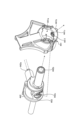
- FIGS. 26 and 27 show the drainage valve 44 shown in FIG. 3, with FIG. 26 being a perspective view showing the external configuration, and FIG. 27 being an exploded perspective view.
- the drainage valve 44 is configured by inserting an inner component 442 into a hollow portion 441a of a cylindrical outer component 441.
- a drainage discharge port 441b is formed in the outer component 441. This drainage discharge port 441b is connected to a drainage path 471 that is provided in a manner that extends to the storage bucket 80. A guide rib 441c that divides the drainage discharge port 441b into two is formed in the opening 4411 that constitutes the drainage discharge port 441b.
- the inner component 442 has a first inner port 442a and a second inner port 442b formed therein, and also has an inlet portion 442c that communicates with the first inner port 442a and the second inner port 442b.
- An O-ring (annular sealing material) 443 is disposed in the inner component 442 so as to surround the inlet portion 442c.
- the first inner port 442a is connected to the filter block 343 (brewer unit 34) through a portion of the beverage supply path 48.
- the second inner port 442b is connected to a beverage supply pipe that is linked to the coffee valve 43.
- the outer component 441 rotates around its own central axis in conjunction with the up and down movement of the filter block 343.
- the inlet 442c of the inner component 442 is positioned opposite the opening 4411 that constitutes the drain discharge port 441b, and the first inner port 442a and the drain discharge port 441b are in communication.
- the first inner port 442a and the second inner port 442b are also in communication.
- the outer component 441 rotates about 90° around its own central axis, eliminating the opposing arrangement between the inlet 442c and the opening 4411 that constitutes the drainage and discharge port 441b, and the inlet 442c is blocked by the inner surface of the outer component 441. This places the first inner port 442a and the second inner port 442b in communication.
- the beverage dispenser 1 described above can dispense coffee to a cup C placed on the stage 22b of the beverage dispenser 22.
- hot water is stored in the hot water tank 61, and in the air valve 41, the air valve shaft 412 is disposed at a reference position, and the air introduction port 411a communicates with the stirring air discharge port 411b and the extraction air discharge port 411c communicates with the release port 411d.
- the hot water introduction port 421a communicates with the mixed hot water discharge port 421b
- the stirring air introduction port 431b communicates with the coffee introduction port 431a.
- the control unit 12 When the user touches the display unit 21, the control unit 12 receives a sales signal for the selected beverage, and as shown in FIG. 28, issues a command to the filter block drive unit 343b to move the filter block 343 upward.
- the filter block 343 rises in this manner, in the drainage valve 44, the opposing arrangement between the inlet portion 442c of the inner component 442 and the opening 4411 that constitutes the drainage discharge port 441b is eliminated, and the inlet portion 442c is blocked by the inner surface of the outer component 441. In other words, in the drainage valve 44, only the first inner port 442a and the second inner port 442b are in communication.
- a drive command is given to the raw material supply drive unit 51a to cause the grinder 32 to dispense an amount of coffee beans corresponding to the beverage.
- the control unit 12 stops driving the raw material supply drive unit 51a.
- the control unit 12 issues a drive command to the pulverizer drive unit 32a while issuing a drive command to the first hot water supply pump 62 and the second hot water supply pump 64.
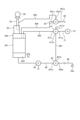
- hot water in the hot water tank 61 is supplied to the mixed hot water nozzle 404 through the hot water valve 42 and the mixed hot water supply path 403, and is discharged as mixed hot water from the mixed hot water nozzle 404, and the coffee beans are pulverized by the pulverizer 32 to discharge the ground coffee beans into the raw material chute unit 33.
- FIG. 29 hot water in the hot water tank 61 is supplied to the mixed hot water nozzle 404 through the hot water valve 42 and the mixed hot water supply path 403, and is discharged as mixed hot water from the mixed hot water nozzle 404, and the coffee beans are pulverized by the pulverizer 32 to discharge the ground coffee beans into the raw material chute unit 33.
- the ground coffee beans fall in the raw material chute unit 33 and mix with the mixed hot water in the air, and the mixture collides with the inner wall surface of the raw material passage 331 before being thrown into the cylinder 341.
- the control unit 12 stops the pulverizer drive unit 32a after discharging a predetermined amount of ground coffee beans, and stops the first hot water supply pump 62 and the second hot water supply pump 64 after discharging a predetermined amount of mixed hot water.
- the control unit 12 drives the air pump 72, and the pressurized air is sent in the order of the air valve 41 (air inlet port 411a-mixing air discharge port 411b), the mixing air line 401, the coffee valve 43, the beverage supply path 48, the drain valve 44 (inner second port 442b-inner first port 442a), and the brewer unit 34, as shown in FIG. 29, to mix the mixture.
- the pressurized air sent to the brewer unit 34 in this way and used to mix the mixture is sent in the order of the extraction air line 402 and the air valve 41 (extraction air discharge port 411c-release port 411d), and is released from the release port 411d.
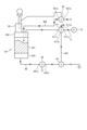
- control unit 12 After stirring the mixture in this manner, the control unit 12 issues a drive command to the valve actuator 40a, displacing the hot water valve shaft 422 of the hot water valve 42 to connect the hot water inlet port 421a to the added hot water outlet port 421c.
- the control unit 12 issues a drive command to the first hot water supply pump 62 and the second hot water supply pump 64, so that, as shown in FIG. 30, hot water in the hot water tank 61 is supplied to the added hot water nozzle through the hot water valve 42 and the added hot water supply path 405, and is discharged from the added hot water nozzle in a shower-like manner as added hot water.
- Pressurized air is also sent in the order of the air valve 41 (air inlet port 411a-mixing air discharge port 411b), the mixing air line 401, the coffee valve 43, the beverage supply path 48, the drain valve 44 (inner second port 442b-inner first port 442a), and the brewer unit 34 to further mix the mixture.
- the pressurized air thus sent to the brewer unit 34 and used to mix the mixture is sent in the order of the extraction air line 402 and the air valve 41 (extraction air discharge port 411c-open port 411d), and is released from the open port 411d.
- the control unit 12 stops driving the first hot water supply pump 62 and the second hot water supply pump 64 after the predetermined amount of added hot water is discharged.
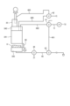
- the control unit 12 drives the pinch motor 36a to bring the first pinch component 361 and the second pinch component 362 closer to each other, as shown in FIG. 31, thereby elastically deforming the lower part of the passage component 35 and closing a part of the passage 351. This allows the inside of the cylinder 341 to be sealed.
- the control unit 12 also issues a drive command to the valve actuator 40a, displacing the air valve shaft 412 of the air valve 41 to the tip position, connecting the air inlet port 411a to the extracted air outlet port 411c. It also connects the coffee inlet port 431a to the coffee outlet port 432a of the coffee valve 43.
- pressurized air from the air pump 72 is sent through the air valve 41 (air inlet port 411a-extracted air outlet port 411c), the extraction air line 402, and the brewer unit 34 in that order, extracting coffee, which is then supplied to the nozzle 22a via the beverage supply path 48 and dispensed from the nozzle 22a into the cup C.
- the control unit 12 issues a drive command to the valve actuator 40a to displace the air valve shaft 412 of the air valve 41 to a reference position, connecting the air inlet port 411a to the stirring air discharge port 411b, connecting the extraction air discharge port 411c to the release port 411d, connecting the stirring air inlet port 431b to the coffee inlet port 431a of the coffee valve 43, and then stops driving the air pump 72.
- the pressurized air used for extraction is sent out in the order of the extraction air line 402 and the air valve 41 (extraction air discharge port 411c - release port 411d), and is released from the release port 411d, thereby reducing the internal pressure of the brewer unit 34.
- the control unit 12 also drives the pinch motor 36a to separate the first pinch component 361 and the second pinch component 362 from each other, thereby elastically deforming the passage component 35 back to its original state and releasing the closed state.
- control unit 12 issues a command to the filter block driving unit 343b to lower the filter block 343.
- the extraction residue K is placed above the filter block 343.
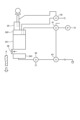
- the control unit 12 After lowering the filter block 343, the control unit 12 issues a forward rotation drive command to the scraper drive mechanism 382 to move the scraper 38 forward from the standby position to the advanced position, as shown in FIG. 33. This allows the extracted residue K to be removed from the upper area of the filter block 343 and discharged into the collection bucket 80. The control unit 12 then issues a reverse rotation drive command to the scraper drive mechanism 382 to move the scraper 38 in the opposite direction from the advanced position to the standby position.
- the control unit 12 drives the exhaust fan 46 when coffee is extracted.
- the intake port 45 for sucking in air is formed above the part where the ground coffee beans are discharged from the grinder 32 to the raw material chute unit 33. Therefore, by driving the exhaust fan 46, as shown by the two-dot chain arrow in FIG. 12, the air sucked in from the intake port 45 passes through the raw material passage 331 and is then discharged to the outside through the exhaust duct 49, and the air inside the cylinder 341 is discharged to the outside via the exhaust duct 49 without passing through the raw material passage 331. This makes it possible to prevent steam from being sent to the part of the grinder 32 where the ground coffee beans are discharged.
- the control unit 12 reduces the rotation speed of the exhaust fan 46 when the ground coffee beans are discharged from the grinder 32.
- the hot water is supplied to the brewer unit 34, etc. as cleaning water to clean the brewer unit 34, etc.
- the hot water (cleaning water) used to clean the brewer unit 34, etc. flows through the drainage path 471 and is discharged into the storage bucket 80 by connecting the first inner port 442a and the drainage discharge port 441b in the drainage valve 44.
- the coffee valve 43 which is the connection destination of the second inner port 442b through the beverage supply path 48, is in a state where the stirring air introduction port 431b and the coffee introduction port 431a are connected, so the cleaning water introduced from the first inner port 442a is not discharged from the second inner port 442b.
- the mixing air line 401 and the extraction air line 402 are cleaned at predetermined intervals (e.g., one year or six months) as follows.
- the control unit 12 When a command to clean the stirring air line 401 and the extraction air line 402 is given, the control unit 12 raises the filter block 343 and then gives a drive command to the valve actuator 40a to move the air valve shaft 412 of the air valve 41 from the reference position to the intermediate position, and communicates the air inlet port 411a, the stirring air discharge port 411b, the extraction air discharge port 411c, and the release port 411d.
- the control unit 12 also positions the hot water valve shaft 422 at the tip position, and communicates the hot water inlet port 421a and the added hot water discharge port 421c in the hot water valve 42.
- the control unit 12 communicates the coffee inlet port 431a and the stirring air inlet port 431b in the coffee valve 43.
- the extractor 30, the stirring air line 401, and the extraction air line 402 are communicated through a part of the beverage supply path 48.
- the control unit 12 drives the first hot water supply pump 62 and the second hot water supply pump 64 to supply hot water to the brewer unit 34 through the added hot water supply path 405.
- the hot water supplied to the brewer unit 34 enters the mixing air line 401 from the beverage supply path 48, and also enters the extraction air line 402 from the brewer unit 34, and is discharged from the open port 411d of the air valve 41. This allows the mixing air line 401 and the extraction air line 402 to be cleaned.
- the ingredient box 51 is composed of a dispensing section 511 and a storage section 512, and an operating section 5115 for engaging and disengaging the storage section 512 with the dispensing section 511 is disposed inside the main body cabinet 10, so that the operating section 5115 can be prevented from being operated by an unintended person. Furthermore, when the storage section 512 is detached from the dispensing section 511, the storage section 512 can be easily cleaned. Therefore, it is possible to prevent ingredients from being extracted while simplifying cleaning of the ingredient box 51.
- the operating unit 5115 is disposed in the dispensing unit 511, and when an operating force is applied to the operating unit 5115, it is disengaged from the locked block 5125, thereby disengaging the dispensing unit 511 from the storage unit 512 and allowing the storage unit 512 to be removed from the dispensing unit 511. Therefore, the operation of the operating unit 5115 and the operation to remove the storage unit 512 from the dispensing unit 511 must be performed with different hands and cannot be performed with one hand.
- the storage section 512 can be detached from the dispensing section 511 by sliding it back and forth relative to the dispensing section 511, which prevents a large amount of raw material from overflowing.
- the scraper 38 is normally positioned in a standby position behind the filter block 343 and close to the drive equipment 383 such as the scraper drive mechanism 382.
- the scraper 38 has a vertical dimension such that the upper end portion 38b is close to the bottom opening 341a of the cylinder 341. Therefore, even if poor extraction by the extractor 30 causes the filter block 343 to descend with beverage inside, causing the beverage to splash, the beverage can be prevented from splashing onto the drive equipment 383.
- the valve shaft (air valve shaft 412 and hot water valve shaft 422) is configured with small diameter sections 412a, 422a and large diameter sections 412b, 422b with different outer diameters
- the valve case (air valve case 411 and hot water valve case 421) is configured by connecting a first valve case component (first air valve case component 4111, first hot water valve case component 4211) in which the inner diameter of the hollow section 4111a, 4211a is smaller than the outer diameter of the large diameter section 412b, 422b, and a second valve case component (second air valve case component 4112, second hot water valve case component 4212) in which the inner diameter of the hollow section 4112a, 4212a is larger than the outer diameter of the large diameter section 412b, 422b, so that the valve shaft can be prevented from coming out of the valve case.
- first valve case component first air valve case component 4111, first hot water valve case component 4211
- second valve case component second air valve case component 4112, second hot water valve case component 4212
- support ribs 417, 427 are formed on the inner surface of the second valve case component, which are capable of sliding contact with O-rings 414, 424 provided at the tip side of the valve shaft. Therefore, when the valve shaft is displaced along the axial direction of the valve case, the O-rings 414, 424 are always in sliding contact with the support ribs 417, 427, which prevents the O-rings 414, 424 from being damaged or twisted due to eccentricity or the like caused by displacement of the valve shaft, thereby extending the service life.
- the tip portions 416, 426 of the valve shafts are umbrella-shaped, and notches 418, 428 are formed in the support ribs 417, 427 at portions spaced apart from the tip of the valve case, so that the piping resistance of the valve case caused by the formation of the support ribs 417, 427 can be reduced.
- the opening 4311 constituting the coffee introduction port 431a in the outer member 431 is formed with a guide rib 431c that divides it into upper and lower parts.
- a part of the O-ring 433 surrounding the inlet portion 432b slides against the guide rib 431c, and the elastic restoring force prevents the O-ring 433 from sliding against the edge of the opening 4311. This prevents damage to the O-ring 433 caused by the rotation of the inner member 432, and extends the service life.
- the coffee inlet port 431a and the stirring air inlet port 431b of the coffee valve 43 are connected to each other, and then the air pump 72 is stopped. This prevents coffee remaining inside the coffee valve 43 from entering the stirring air line 401 when the state of communication between the coffee inlet port 431a and the coffee discharge port 432a is switched from a state of communication between the coffee inlet port 431a and the stirring air inlet port 431b.
- the control unit 12 on the condition that a cleaning command is given, brings the extractor 30, the stirring air line 401, and the extraction air line 402 into communication and fills them with hot water, so that the stirring air line 401 and the extraction air line 402 can also be cleaned well, which was previously difficult to do.
- the drain valve 44 is linked to the vertical movement of the filter block 343.
- the inlet 442c of the inner component 442 is blocked by the inner surface of the outer component 441.
- the inlet 442c of the inner component 442 faces the opening 4411 that constitutes the drain discharge port 441b.
- the filter block 343 when performing cleaning by supplying cleaning hot water to the brewer unit 34 or the like, the filter block 343 is lowered, so that the inlet 442c of the inner component 442 faces the opening 4411 of the waste liquid discharge port 441b, and the cleaning hot water is discharged into the storage bucket 80 through the drainage path 471.
- the filter block 343 is raised again to re-introduce hot water into the cylinder 341, and then the filter block 343 is lowered, so that the re-introduced hot water passes through the waste liquid discharge port 441b, thereby cleaning the waste liquid discharge port 441b.
- the ingredient chute section 33 can be cleaned as follows. That is, the pinch mechanism 36 elastically deforms the lower part of the passageway component 35 to close a portion of the passageway 351, and then the first hot water supply pump 62 and the second hot water supply pump 64 are driven to supply hot water to the ingredient chute section 33 and retain it there, thereby cleaning the ingredient chute section 33.
- the hot water used to clean the ingredient chute section 33 can then be released from the closed state of the passageway component 35 by the pinch mechanism 36, and poured into the brewer unit 34 or the like, and discharged.
- the filter block 343 may be raised, and the first hot water supply pump 62 and the second hot water supply pump 64 may be driven to store hot water in the cylinder 341 and the passage component 35.
- the air pump 72 may be driven to send air in the following order: air valve 41 (air inlet port 411a-mixing air outlet port 411b), mixing air line 401, coffee valve 43, beverage supply path 48, drain valve 44 (inner second port 442b-inner first port 442a), and brewer unit 34, to stir the stored hot water.
- a strainer may be provided near the outlet of the extraction air line in the top seal section. This can prevent extraction residue and the like from entering the extraction air line.
- the hot water supply unit 60 includes a first hot water pump 62, a sub-tank 63, and a second hot water pump 64.
- the first hot water pump 62 which is a centrifugal pump
- the sub-tank 63 may be eliminated
- a second hot water pump which is a gear pump, and a flow meter may be provided. This makes it possible to suppress a drop in temperature caused by temporarily storing hot water in the sub-tank 63.
- hot water can be added to the brewer unit 34 as additional hot water to extract the coffee.
- 1...beverage supply device 10...main cabinet, 11...production unit, 12...control unit, 20...front door, 22...beverage supply unit, 30...extractor, 50...ingredient supply unit, 60...hot water supply unit, 70...air supply unit, 80...container bucket, C...cup.
Landscapes
- Engineering & Computer Science (AREA)
- Food Science & Technology (AREA)
- Apparatus For Making Beverages (AREA)
- Devices For Dispensing Beverages (AREA)
Abstract
L'invention concerne un dispositif de distribution de boisson (1) comprenant une boîte de matière première (51) dans laquelle une matière première est reçue et stockée, et qui évacue la matière première vers un extracteur (30) par entraînement d'une unité d'entraînement d'alimentation en matière première intégrée (51a), le dispositif de distribution de boisson (1) fournissant une boisson produite avec l'extracteur (30) à une tasse C. La boîte de matière première (51) comprend : une unité de distribution (511) pourvue de l'unité d'entraînement d'alimentation en matière première intégrée (51a) et délivrant la matière première à l'extracteur (30) par entraînement de l'unité d'entraînement d'alimentation en matière première (51a) ; et une portion de réception (512) qui, en étant en prise avec l'unité de distribution (511) avec un orifice de communication (5122) de la portion de réception (512) qui est en communication avec un orifice d'introduction (5112) de l'unité de distribution (511), est disposée avec une partie de celle-ci exposée depuis un corps d'armoire (10), et est disposée de manière amovible par rapport à l'unité de distribution (511). Une unité d'actionnement (5115) destinée à mettre en prise et libérer la partie de réception (512) avec ou de l'unité de distribution (511) est disposée à l'intérieur du corps d'armoire (10).
Priority Applications (1)
| Application Number | Priority Date | Filing Date | Title |
|---|---|---|---|
| CN202480034531.4A CN121174970A (zh) | 2023-07-03 | 2024-04-24 | 饮料供给装置 |
Applications Claiming Priority (2)
| Application Number | Priority Date | Filing Date | Title |
|---|---|---|---|
| JP2023-109285 | 2023-07-03 | ||
| JP2023109285A JP7480897B1 (ja) | 2023-07-03 | 2023-07-03 | 飲料供給装置 |
Publications (1)
| Publication Number | Publication Date |
|---|---|
| WO2025009251A1 true WO2025009251A1 (fr) | 2025-01-09 |
Family
ID=90926030
Family Applications (1)
| Application Number | Title | Priority Date | Filing Date |
|---|---|---|---|
| PCT/JP2024/016155 Ceased WO2025009251A1 (fr) | 2023-07-03 | 2024-04-24 | Dispositif de distribution de boisson |
Country Status (4)
| Country | Link |
|---|---|
| JP (1) | JP7480897B1 (fr) |
| CN (1) | CN121174970A (fr) |
| TW (1) | TWI900076B (fr) |
| WO (1) | WO2025009251A1 (fr) |
Citations (8)
| Publication number | Priority date | Publication date | Assignee | Title |
|---|---|---|---|---|
| JPS51147098U (fr) * | 1975-05-19 | 1976-11-25 | ||
| JPS57194178U (fr) * | 1981-05-28 | 1982-12-09 | ||
| JPH1043057A (ja) * | 1996-08-08 | 1998-02-17 | Ckd Corp | 小形粉末吐出装置 |
| JPH1097679A (ja) * | 1996-09-20 | 1998-04-14 | U C C Ueshima Cafe Kk | 自動販売機 |
| CN107252256A (zh) * | 2017-07-04 | 2017-10-17 | 安徽兰兮工程技术开发有限公司 | 用于饮品机的防止物料粘附取料凹槽壁的取料设备 |
| JP2019030437A (ja) * | 2017-08-07 | 2019-02-28 | 株式会社Tree Field | 飲料製造装置 |
| JP2021065346A (ja) * | 2019-10-21 | 2021-04-30 | 株式会社Tree Field | 抽出方法 |
| JP2023025652A (ja) * | 2021-08-10 | 2023-02-22 | 富士電機株式会社 | 飲料供給装置 |
-
2023
- 2023-07-03 JP JP2023109285A patent/JP7480897B1/ja active Active
-
2024
- 2024-04-24 CN CN202480034531.4A patent/CN121174970A/zh active Pending
- 2024-04-24 WO PCT/JP2024/016155 patent/WO2025009251A1/fr not_active Ceased
- 2024-06-24 TW TW113123385A patent/TWI900076B/zh active
Patent Citations (8)
| Publication number | Priority date | Publication date | Assignee | Title |
|---|---|---|---|---|
| JPS51147098U (fr) * | 1975-05-19 | 1976-11-25 | ||
| JPS57194178U (fr) * | 1981-05-28 | 1982-12-09 | ||
| JPH1043057A (ja) * | 1996-08-08 | 1998-02-17 | Ckd Corp | 小形粉末吐出装置 |
| JPH1097679A (ja) * | 1996-09-20 | 1998-04-14 | U C C Ueshima Cafe Kk | 自動販売機 |
| CN107252256A (zh) * | 2017-07-04 | 2017-10-17 | 安徽兰兮工程技术开发有限公司 | 用于饮品机的防止物料粘附取料凹槽壁的取料设备 |
| JP2019030437A (ja) * | 2017-08-07 | 2019-02-28 | 株式会社Tree Field | 飲料製造装置 |
| JP2021065346A (ja) * | 2019-10-21 | 2021-04-30 | 株式会社Tree Field | 抽出方法 |
| JP2023025652A (ja) * | 2021-08-10 | 2023-02-22 | 富士電機株式会社 | 飲料供給装置 |
Also Published As
| Publication number | Publication date |
|---|---|
| TW202517197A (zh) | 2025-05-01 |
| JP2025007708A (ja) | 2025-01-17 |
| JP7480897B1 (ja) | 2024-05-10 |
| TWI900076B (zh) | 2025-10-01 |
| CN121174970A (zh) | 2025-12-19 |
Similar Documents
| Publication | Publication Date | Title |
|---|---|---|
| JP5115097B2 (ja) | 飲料抽出装置およびこれを備えた飲料供給装置 | |
| JP5537987B2 (ja) | ミルクフォーマー及び飲料製造装置 | |
| JP7480897B1 (ja) | 飲料供給装置 | |
| JP7738033B2 (ja) | 切替バルブ | |
| KR102480177B1 (ko) | 음료 공급 장치 | |
| JP2025007741A (ja) | 飲料供給装置 | |
| JP2023025652A (ja) | 飲料供給装置 | |
| JP5338509B2 (ja) | カップ式飲料自動販売機 | |
| JP2011167396A (ja) | 飲料製造装置 | |
| JP7485184B1 (ja) | 飲料供給装置 | |
| JP7414085B2 (ja) | 飲料供給装置 | |
| JP7414086B2 (ja) | 飲料抽出装置 | |
| JP2025085185A (ja) | 飲料供給装置 | |
| WO2023176976A1 (fr) | Dispositif d'alimentation en boisson | |
| JP7509325B1 (ja) | 飲料供給装置 | |
| TWI852514B (zh) | 飲料供給裝置 | |
| JP2025110200A (ja) | 飲料供給装置 | |
| JP2023136745A (ja) | 飲料供給装置 | |
| JP2023137016A (ja) | 切替バルブ | |
| JP2023136827A (ja) | 飲料供給装置 | |
| JP2023136744A (ja) | 飲料供給装置 | |
| CN112804918A (zh) | 饮料供给装置 | |
| WO2024161693A1 (fr) | Dispositif de distribution de boisson | |
| JP2024110902A (ja) | 飲料供給装置 | |
| JP2024165441A (ja) | 飲料供給装置 |
Legal Events
| Date | Code | Title | Description |
|---|---|---|---|
| 121 | Ep: the epo has been informed by wipo that ep was designated in this application |
Ref document number: 24835773 Country of ref document: EP Kind code of ref document: A1 |
|
| NENP | Non-entry into the national phase |
Ref country code: DE |