WO2025009420A1 - Dispositif de commande, dispositif de traitement d'informations et procédé - Google Patents
Dispositif de commande, dispositif de traitement d'informations et procédé Download PDFInfo
- Publication number
- WO2025009420A1 WO2025009420A1 PCT/JP2024/022660 JP2024022660W WO2025009420A1 WO 2025009420 A1 WO2025009420 A1 WO 2025009420A1 JP 2024022660 W JP2024022660 W JP 2024022660W WO 2025009420 A1 WO2025009420 A1 WO 2025009420A1
- Authority
- WO
- WIPO (PCT)
- Prior art keywords
- trajectory
- partial
- robot
- trajectories
- control unit
- Prior art date
- Legal status (The legal status is an assumption and is not a legal conclusion. Google has not performed a legal analysis and makes no representation as to the accuracy of the status listed.)
- Ceased
Links
Images






Classifications
-
- B—PERFORMING OPERATIONS; TRANSPORTING
- B25—HAND TOOLS; PORTABLE POWER-DRIVEN TOOLS; MANIPULATORS
- B25J—MANIPULATORS; CHAMBERS PROVIDED WITH MANIPULATION DEVICES
- B25J9/00—Program-controlled manipulators
- B25J9/16—Program controls
- B25J9/1656—Program controls characterised by programming, planning systems for manipulators
-
- G—PHYSICS
- G05—CONTROLLING; REGULATING
- G05B—CONTROL OR REGULATING SYSTEMS IN GENERAL; FUNCTIONAL ELEMENTS OF SUCH SYSTEMS; MONITORING OR TESTING ARRANGEMENTS FOR SUCH SYSTEMS OR ELEMENTS
- G05B19/00—Program-control systems
- G05B19/02—Program-control systems electric
- G05B19/18—Numerical control [NC], i.e. automatically operating machines, in particular machine tools, e.g. in a manufacturing environment, so as to execute positioning, movement or co-ordinated operations by means of program data in numerical form
- G05B19/4155—Numerical control [NC], i.e. automatically operating machines, in particular machine tools, e.g. in a manufacturing environment, so as to execute positioning, movement or co-ordinated operations by means of program data in numerical form characterised by program execution, i.e. part program or machine function execution, e.g. selection of a program
-
- G—PHYSICS
- G05—CONTROLLING; REGULATING
- G05B—CONTROL OR REGULATING SYSTEMS IN GENERAL; FUNCTIONAL ELEMENTS OF SUCH SYSTEMS; MONITORING OR TESTING ARRANGEMENTS FOR SUCH SYSTEMS OR ELEMENTS
- G05B19/00—Program-control systems
- G05B19/02—Program-control systems electric
- G05B19/42—Recording and playback systems, i.e. in which the program is recorded from a cycle of operations, e.g. the cycle of operations being manually controlled, after which this record is played back on the same machine
Definitions
- This disclosure relates to a control device and method for causing a robot to perform a specified operation, and an information processing device and method for controlling machine learning to cause a robot to perform a specified operation.
- Patent Document 1 discloses a method for generating an operation program for a dual-arm robot.
- the variables of a template element operation program that causes the robot to execute each element task that constitutes the robot's overall work are specified by user input using a GUI.
- the template element operation program includes as variables one or more hand position coordinates (instruction points) that define the robot's motion (movement and posture change) required for the element task, and is configured so that the robot's motion is specified by specifying all of the hand position coordinates.
- an instructor who teaches the robot to move can generate an operation program for the motion operation that includes the robot's hand position coordinates, simply by specifying the variables of the template element operation program using a GUI.
- the present disclosure provides a control device, information processing device, and method that can facilitate accurate robot operation.
- a control device is a control device that causes a robot to perform a predetermined operation.
- the control device includes a communication unit that performs data communication with an external device, and a control unit that controls the robot by data communication via the communication unit.
- a plurality of partial trajectories are set by dividing a trajectory that indicates the movement of the robot in a predetermined operation.
- the plurality of partial trajectories include a first partial trajectory and a second partial trajectory that are adjacent to each other in the trajectory.
- the first and second partial trajectories have an overlapping portion where the first and second partial trajectories overlap, a first independent portion that is only the first partial trajectory, and a second independent portion that is only the second partial trajectory.
- the control unit causes the robot to perform a predetermined operation in accordance with both the first and second partial trajectories.
- An information processing device controls machine learning to make a robot perform a predetermined operation.
- the information processing device includes a display unit that displays information, an input unit that accepts user operations, and a control unit that controls the display unit and the input unit.
- the control unit causes the display unit to display a trajectory showing the movement of the robot in the predetermined operation.
- the control unit accepts user operations in the input unit related to the trajectory displayed on the display unit and sets multiple partial trajectories that divide the trajectory.
- the control unit controls machine learning to make the robot perform a predetermined operation for each partial trajectory according to the partial trajectory set by the user operation.
- the partial trajectories set as multiple partial trajectories that divide the trajectory overlap each other in adjacent portions of the trajectory.
- control device information processing device, and method disclosed herein can make it easier to operate a robot with high precision.
- FIG. 1 is a diagram for explaining an overview of a control system according to a first embodiment.
- a block diagram illustrating the configuration of a robot, a robot control device, and a terminal device in a control system.
- FIG. 1 is a diagram for explaining the operation of a control system.
- a sequence diagram illustrating the overall operation of the control system 1 is a flowchart illustrating a trajectory division process in a terminal device according to a first embodiment;
- FIG. 13 is a diagram showing a display example in a trajectory division process in the terminal device of the first embodiment;
- FIG. 13 is a diagram showing an example of expanding overlapping portions of partial trajectories in trajectory division processing; A diagram for explaining the relationship between the correction term of the control model and the division of the trajectory.
- FIG. 13 is a diagram showing a display example in a trajectory division process in a terminal device according to a second embodiment; 11 is a flowchart illustrating a trajectory division process in a terminal device according to a second embodiment;
- FIG. 1 is a diagram for explaining an overview of a control system 1 according to this embodiment.
- the control system 1 of this embodiment includes a robot 2, a robot control device 4, and a terminal device 5.
- the robot 2, the robot control device 4, and the terminal device 5 are connected to each other so as to be able to communicate data with each other.
- This system 1 is applied to an application in which the operation of a robot 2 is controlled by a control command transmitted from a robot control device 4, for example.
- the robot 2 operates in response to the control command, for example by driving a manipulator including multiple joints.
- the robot 2 moves the connector 6 of the USB terminal and inserts it into a socket 7.
- Such an operation of the robot 2 is an example of a predetermined operation in this embodiment.
- Fig. 2 is a block diagram illustrating the configurations of the robot 2, robot control device 4, and terminal device 5 in the control system 1.
- the robot 2 includes a control unit 20 and a communication interface 22.
- interface will be abbreviated as "I/F.”
- the control unit 20 is composed of various processors such as a CPU, and controls the overall operation of the robot 2.
- the communication I/F 22 is a circuit for performing data communication according to a predetermined communication standard.
- the predetermined communication standard includes USB, IEEE 1395, IEEE 802.3, IEEE 802.11a/11b/11g/11ac, Wi-Fi (registered trademark), and Bluetooth (registered trademark).
- the communication I/F 22 may be configured to include a connection terminal for connecting to an external device, and may communicate with an external device via a communication network or directly.
- the communication I/F 22 may be configured with multiple circuits.
- the control unit 20 of the robot 2 receives control commands from the robot control device 4 via the communication I/F 22, and drives each joint of the manipulator based on the control commands. Furthermore, the robot 2 is equipped with a driving device such as a motor that drives each joint. The robot 2 may also be equipped with a sensor that detects displacement, such as the rotation angle of each joint. For example, from the displacements detected sequentially during direct teaching or the like, the control unit 20 may calculate coordinate data indicating the coordinates corresponding to the position or posture at which the tip of the manipulator operates, i.e., the hand coordinates, and transmit the coordinate data to an external device such as the robot control device 4 via the communication I/F 22. The hand coordinates are represented in a coordinate system based on a base to which the manipulator is fixed in the robot 2, as shown in FIG. 1, for example.
- the robot control device 4 comprises a control unit 40, a memory unit 41, and a communication I/F 42.
- the control unit 40 is composed of various processors such as a CPU, and realizes predetermined functions such as controlling the communication I/F 42, for example, by executing a program (software) stored in the memory unit 41.
- the memory unit 41 is a storage medium that stores the above-mentioned programs, and is composed of, for example, a non-volatile semiconductor memory.
- the memory unit 41 may include a RAM such as a DRAM or SRAM, and may function as a work memory for the control unit 40.
- the communication I/F 42 is, for example, a circuit for performing data communication according to a predetermined communication standard, similar to the communication I/F 22 of the robot 2.
- the terminal device 5 includes a control unit 50, a storage unit 51, a communication I/F 52, an operation unit 53, and a display unit 54.
- the terminal device 5 is configured as an information processing device such as a personal computer (PC).
- the control unit 50 includes, for example, a CPU, and executes a program (software) using the CPU to realize a specified function in the terminal device 5.
- the control unit 50 may include a processor configured with a dedicated electronic circuit designed to realize the specified function.
- the control unit 50 can be realized by various processors such as a CPU, MPU, GPU, DSU, FPGA, ASIC, etc.
- the control unit 50 may be configured with one or more processors.
- the storage unit 51 may also include a RAM, such as a DRAM or an SRAM, and may function as a buffer memory that temporarily stores (i.e., holds) data.
- the storage unit 51 may also function as a working area for the control unit 50, and may include a storage area in the internal memory of the control unit 50.
- the communication I/F 52 is a circuit for performing data communication according to a predetermined communication standard, similar to the communication I/F 42 of the robot control device 4, for example.
- the communication I/F 52 may constitute an acquisition unit that receives various information through communication with an external device, or an output unit that transmits various information.
- the display unit 54 is configured, for example, with a liquid crystal display or an organic EL display, and displays a GUI used for machine learning of the control model 30.
- the display unit 54 may display various information such as various icons for operating the operation unit 53 and information input from the operation unit 53.
- control system 1 includes a robot control device 4 and a terminal device 5, but the configuration of the control system 1 is not limited to the above example.
- the robot control device 4 may be configured integrally with the robot 2, or may be configured integrally with the terminal device 5.
- control model 30, etc. are stored in the memory unit 51 of the terminal device 5, but they may also be stored in a storage device external to the terminal device 5.
- the control system 1 of this embodiment performs machine learning of the control model 30 in the terminal device 5 so that the robot 2 performs the action desired by the user based on the trajectory of the robot 2's movement during direct teaching by the user, etc.
- the terminal device 5 of the system 1 acquires, for example, as shown in FIG. 1, from the robot 2 via the robot control device 4, the trajectory of the operation of the robot 2 inserting the connector 6 into the socket 7.
- a trajectory may be acquired by interactive control in which the user operates the robot 2 while making fine adjustments remotely.
- the terminal device 5 updates the control model 30 by machine learning, for example, each time a trajectory of one or more movements of the robot 2 is obtained.
- the control model 30 of this embodiment is trained to output torque commands to a motor that operates the robot 2 by impedance control, sequentially from coordinates at each time according to a trajectory in the space in which the robot 2 operates, for example.
- the system 1 inputs the current coordinates of the robot 2 into the trained control model 30 and outputs a torque command to the motor at the coordinates as a control command, thereby operating the robot 2.
- Fig. 3 is a diagram for explaining an issue in learning a control model 30 using a trajectory of the robot 2.
- FIG. 3(A) shows an example in which the robot 2 moves the connector 6 by direct teaching or the like in an operation similar to that in the example of FIG. 1.
- This operation includes an approach stage in which the connector 6 approaches the socket 7, a slide stage in which the connector 6 that has come into contact with the upper surface of the socket 7 is slid up to the recess in the socket 7, and an insertion stage in which the connector 6 is inserted into the recess in the socket 7.
- a force is applied to the robot 2 in the right direction (+X direction) in the figure, by direct teaching or the like, during the sliding stage, so as to counter the friction caused by contact between the connector 6 and the socket 7.
- FIG. 3(B) shows an example in which the control model 30 is updated using the trajectory obtained in the example of FIG. 3(A) as is, and then the robot 2 moves the connector 6 in response to a control command from the control model 30.
- a control model 30 that is updated regardless of the stage of the operation, it may be difficult to make the robot 2 perform operations corresponding to each stage as described above.
- the operation may be changed even to an approach stage other than the sliding stage intended by the user, and the arrival point of the connector 6 in that stage may shift in the +X direction, causing it to pass through the recess in the socket 7.
- the control system 1 of this embodiment therefore divides the trajectory obtained by direct teaching or the like according to the stage of the movement through user operation, and performs machine learning of the control model 30 using the divided trajectories. For example, a user can distinguish between stages where the movement switches based on the trajectory of the robot 2.
- the terminal device 5 of this system 1 accepts a user operation for dividing the trajectory while displaying it, and provides a GUI that makes it easy to learn the control model 30 so as to operate the robot 2 with high accuracy.
- FIG. 4 is a diagram for explaining the operation of the control system 1.
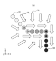
- FIG. 4 shows an example in which the results of dividing a trajectory from a start point C1 to an end point C2 of a movement of a robot 2 that operates in the same manner as in the example of FIG. 1 are displayed on the display unit 54 of the terminal device 5.
- the system 1 divides the trajectory from the start point C1 to the end point C2, for example, according to each stage of the approach, slide, and insertion where the behavior of the robot 2 changes relatively greatly, based on the user's operation on the terminal device 5.
- the terminal device 5 displays the points indicating the coordinates at each time on the trajectory in different forms depending on the divided parts.
- the terminal device 5 divides the entire trajectory in response to a user operation so that adjacent trajectories after division have overlapping portions.
- the robot 2 can be controlled so that the stages of operation corresponding to each divided trajectory gradually switch in a cross-fade manner. In this way, the terminal device 5 of this system 1 makes it easier to learn the control model 30 so as to operate the robot 2 with high accuracy.
- the terminal device 5 of this embodiment visualizes the movement direction of the robot 2 according to the output of the control model 30 around the trajectory by using an arrow Vt, as shown in FIG. 4, for example.
- the arrow Vt indicates the movement direction according to the relative displacement from any coordinate in the space in which the robot 2 operates to the next target coordinate of the robot 2 output by the control model 30.
- the user can, for example, check the operation of the robot 2 according to the control model 30 updated based on the trajectory after division, and adjust the division, etc.
- FIG. 5 is a sequence diagram illustrating the overall operation of the control system 1.
- the control system 1 acquires coordinate data and the like obtained by the operation of the robot 2 as a trajectory (S1).
- the control system 1 accepts a user operation to divide the trajectory, and updates the control model 30 by machine learning using the divided trajectory (S2).
- the system 1 uses the control model 30 updated by this trajectory division process (S2) to calculate control commands from the coordinate data of the robot 2, and operates the robot 2 (S3).
- step S1 the robot 2 of this system 1 transmits coordinate data indicating the hand coordinates of the manipulator tip to the robot control device 4 while operating the manipulator in accordance with, for example, direct teaching.
- the control unit 20 of the robot 2 sequentially calculates the hand coordinates by calculating forward kinematics based on the rotation angle of each joint in the operation of the manipulator, and transmits them via the communication I/F 22.
- the robot control device 4 acquires the coordinate data from the robot 2 by, for example, controlling the communication I/F 42 with the control unit 40, and transmits the acquired coordinate data to the terminal device 5.
- the control unit 50 of the terminal device 5 inputs the coordinate data received from the robot control device 4 via the communication I/F 52, for example, into the initialized control model 30, and calculates a control command for the robot 2 (S1). For example, before executing step S1, a process may be performed to initialize parameters and the like included in the control model 30 with predetermined initial values.
- the robot control device 4 receives the calculated control command from the terminal device 5 and transmits it to the robot 2.
- the control unit 20 of the robot 2 further operates the manipulator based on the received control command.
- step S1 for example, by repeating the above process, coordinate data sequentially acquired as the trajectory of the robot 2 and control commands calculated from the coordinate data are accumulated.
- the terminal device 5 associates the coordinate data obtained during the operation of the robot 2 by such direct teaching or the like with behavioral data indicating the control commands for each time period, and stores them in the memory unit 51 as trajectory data D1.
- the terminal device 5 displays a trajectory based on the collected trajectory data D1 and accepts a user operation to divide the trajectory (S2).
- the terminal device 5 executes machine learning of the control model 30 based on the trajectory data D1 divided in response to the user operation (S2). The process of step S2 will be described in detail later.
- step S3 similar to step S1, the system 1 sequentially acquires current coordinate data of the robot 2 via the robot control device 4, and calculates control commands from the coordinate data using the learned control model 30 in the terminal device 5.
- the robot 2 operates the manipulator based on the control commands received from the terminal device 5 via the robot control device 4.
- the system 1 causes the robot 2 to execute the operations learned by the control model 30.
- steps S1 and S2 may be performed multiple times (e.g., three times), and then the processing of step S3 may be performed by the control model 30 updated based on the trajectory data D1 of each of the multiple operations.
- step S2 in FIG. 5 will be described in detail with reference to FIGS.
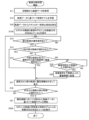
- FIG. 6 is a flowchart illustrating the trajectory division process (S2) in the terminal device 5 of this embodiment.
- the process of this flowchart is started in a state where the trajectory data D1 obtained in step S1 of FIG. 5 is stored in the memory unit 51 of the terminal device 5, and is executed by the control unit 50.
- the coordinates in the trajectory data D1 are described using two axes, the X axis and the Y axis, but it may be three axes, for example, X, Y, and Z, or it may be six axes by adding roll, pitch, and yaw to the three axes.
- the control unit 50 acquires the trajectory data D1 stored in the memory unit 51 (S11).
- Xt and Yt are respectively the X and Y coordinates of the hand of the robot 2, i.e., the tip of the manipulator, at time t.
- VXt and VYt are respectively the relative displacements of the hand coordinates in the X-axis and Y-axis directions from time t to t+1.
- the control unit 50 performs machine learning of the control model 30 based on the acquired trajectory data D1 (S12).
- the control model 30 is trained using the entire trajectory obtained by one movement of the robot 2 in the trajectory data D1.
- the control unit 50 Based on the trajectory data D1, the control unit 50 causes the display unit 54 to display the trajectory of the robot 2's movement and an arrow Vt corresponding to the direction of movement of the robot 2 according to the control model 30 (S13).
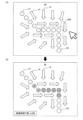
- FIG. 7 is a diagram showing an example of the display in the trajectory division process (S2) in the terminal device 5 of this embodiment. As shown in FIG. 7(A), for example, the display unit 54 displays the trajectory from the start point C1 to the end point C2 of the robot 2's movement and an arrow Vt indicating the direction of movement corresponding to the relative displacement of the robot 2 from time t to t+1 output by the control model 30 from any coordinates around the trajectory.
- the control unit 50 judges whether a user operation has been inputted in the operation unit 53 to select a portion of the entire trajectory in the trajectory data D1 as a partial trajectory by which the trajectory is divided (S14).
- FIG. 7(A) shows an example of a partial trajectory selected by such a user operation.
- the control unit 50 accepts an operation in which the user selects an area R1 including a desired partial trajectory using the operation unit 53 such as a mouse, as shown in FIG. 7(A), for example.
- the user can select a partial trajectory from the trajectory from the start point C1 to the end point C2 displayed on the display unit 54 in response to a change in the operation of the robot 2, etc. If a selection operation has not been inputted (NO in S14), the control unit 50 repeats the judgment of step S14, for example at a predetermined cycle.
- control unit 50 determines whether the selected partial trajectory is the first partial trajectory that was initially divided (S15).
- the control unit 50 may manage the number of divided partial trajectories, for example, in an internal memory, using a counter or the like.
- the control unit 50 assigns attribute information D2 indicating, for example, the first partial trajectory to the partial trajectory (S17).
- the attribute information D2 is managed by associating a predetermined discrete value with a period defined by the start time and end time of the partial trajectory for each partial trajectory, for example, so as to identify the divided partial trajectories.
- the control unit 50 updates the display on the display unit 54 according to the assigned attribute information D2 (S17). For example, as shown in FIG. 7(B), the control unit 50 displays the partial trajectory selected in the region R1 in FIG. 7(A) and assigned with attribute information D2 in a manner different from the other partial trajectories.
- the display unit 54 changes the color and pattern of the partial trajectory according to the attribute information D2.
- the control unit 50 refers to a counter in an internal memory, and determines whether a predetermined number of partial trajectories have been selected (S18).
- the number of divisions may be set in advance by a user operation on the operation unit 53, or may be set, for example, in response to a user operation instructing the end of division, as the number of partial trajectories selected by the time of the end by that instruction.
- control unit 50 determines whether or not a selection operation for the next partial trajectory has been input to the operation unit 53 (S14).
- the control unit 50 judges whether there is an overlap between the partial trajectories selected by the current and previous selection operations (S16).
- An overlap indicates, for example, an overlapping period in a portion of each period of two partial trajectories that are continuous in time, i.e., adjacent, partial trajectories. For example, for two adjacent partial trajectories, the control unit 50 detects whether the two partial trajectories partially overlap, i.e., whether there is an overlap between the two partial trajectories, based on the period of each partial trajectory selected by a user operation.
- FIG. 7(B) shows an example in which, after updating the display in accordance with the attribute information D2 added from the example in FIG. 7(A) (S17), a second partial trajectory is selected by a user operation to select region R2 (YES in S14, NO in S15).
- region R2 is selected so that the first partial trajectory selected in region R1 in FIG. 7(A) and the second partial trajectory have an overlapping portion.
- control unit 50 proceeds to step S17, assigns attribute information D2 to the currently selected partial trajectory that is different from the first partial trajectory, and updates the display according to the assigned attribute information D2.
- control unit 50 displays, for example, on the display unit 54, a setting screen for setting a lower limit value of the overlapping time indicating the period of the overlapping portion, and judges whether or not a user operation for inputting a lower limit value on the screen has been input to the operation unit 53 (S19). If the user operation has not been input (NO in S19), the control unit 50 repeats the judgment of step S19, for example, at a predetermined interval.
- the control unit 50 expands each partial trajectory between the current time and the previous time so that it has an overlapping portion where the overlap time is equal to or greater than the input lower limit value (S20). Through the above process, the control unit 50 sets partial trajectories that overlap each other from the two partial trajectories input by the user's selection operation.
- FIG. 8 shows an example of expanding overlapping parts of partial trajectories in the trajectory division process (S2).
- FIG. 8(A) shows an example in which a second partial trajectory is selected from the example of FIG. 7(A) by region R20, and there is no overlapping part between that partial trajectory and the first partial trajectory.
- FIG. 8(B) shows an example in which the user inputs "0.2 seconds" as the lower limit of the overlap time from the example of FIG. 8(A), and the two partial trajectories are expanded in accordance with that lower limit.
- control unit 50 After expanding each partial trajectory (S20), the control unit 50 performs the process of step S17 in the same manner as when there is an overlap between partial trajectories selected by user operation (YES in S16).
- the control unit 50 repeats the process from step S14 onwards while the predetermined number of partial trajectories have not been selected (NO in S18).
- the control unit 50 updates the control model 30 by machine learning, for example, based on the trajectory data D1 divided according to the attribute information D2 (S21).
- the control model 30 includes multiple control models each corresponding to each partial trajectory.
- the control unit 50 learns a control model corresponding to each partial trajectory using data for the period of each partial trajectory in the trajectory data D1, for example, based on the attribute information D2. Details of the control model 30 will be described later.
- the control unit 50 uses the updated control model 30 to display the trajectory of the robot 2 and the arrow Vt of the movement direction on the display unit 54, for example, as in step S13 (S22). At this time, the control unit 50 displays each partial trajectory in a different manner, for example, by changing the color of each divided partial trajectory according to the attribute information D2 assigned to each partial trajectory, as shown in FIG. 4. The control unit 50 also displays, for example, multiple colors superimposed at overlapping portions according to the attribute information D2 of each partial overlapping trajectory.
- the arrow Vt of the movement direction according to the updated control model 30 is drawn according to an output that integrates the inference results of each control model, for example, using parameters obtained by learning the control model corresponding to each partial trajectory.
- the control unit 50 displays the trajectory of the robot 2 and the arrow Vt indicating the direction of movement according to the updated control model 30 (S22), and then ends the processing of this flowchart.
- the control model 30 can be updated by machine learning so that, for example, the robot 2 can be controlled with high accuracy in response to changes in motion (S21).
- the terminal device 5 of this embodiment can control the machine learning of the control model 30 so as to cause the robot 2 to perform each stage of the motion exemplified in FIG. 4 and the like in response to the attribute information D2 assigned to each partial trajectory. For example, it is possible to cause the robot to learn different motions in response to each partial trajectory.
- each partial trajectory is expanded (S29) according to the lower limit of the overlap time input by the user (S19). This makes it possible to divide the trajectory so that each partial trajectory has an overlapping portion.
- the direction of movement of the robot 2 according to the control model 30 is displayed by an arrow Vt (S13, S22).
- Vt the direction of movement of the robot 2 according to the control model 30.
- control model 30 is updated by machine learning (S21) after partial trajectories have been selected up to a predetermined number of divisions (YES in S18).
- the control model 30 may be updated before the number of selected partial trajectories reaches the predetermined number of divisions, and for example, machine learning of the corresponding control model may be performed each time attribute information D2 is assigned to a selected partial trajectory (S17).
- the display of the movement direction arrow Vt may be updated.
- the terminal device 5 accepts a user operation to input a lower limit value for the overlap time (S19).
- the lower limit value is not limited to the overlap time, and may be input as a lower limit of an amount indicating the degree of overlap, for example, by the number of data points of coordinate data at the overlapping location.
- step S20 it is not limited to both partial trajectories selected this time and last time, but one of the partial trajectories may be expanded so that the partial trajectories partially overlap each other.
- control model 30 learned based on the trajectory data D1 divided in the trajectory division process (S2) described above will be described in detail with reference to FIG.
- the control model 30 of this embodiment is realized as a regression model using Gaussian process regression, as used in, for example, Non-Patent Document 1.
- the following formula (1) shows the kernel matrix K calculated from the coordinate data x(t) of the hand coordinate at each time in Gaussian process regression.
- k(x (i) , x (j) ) (i, j ⁇ 1, 2,...,N ⁇ ) in formula (1) is a kernel function.
- the Gaussian kernel shown in formula (2) is used as the kernel function.
- the kernel function is not limited to the Gaussian kernel, and may be, for example, an exponential kernel or a periodic kernel.
- the trained control model infers action data y * , which is an unknown output, by Gaussian process regression for coordinate data x * indicating input unknown (i.e. untrained) hand coordinates.
- the control model calculates a kernel function between unknown coordinate data x * and the coordinate data x (1) , x (2) , ..., x (N) included in the learning data, i.e., the trajectory data D1.
- the kernel matrix K in equation (3) is calculated from the learning data using the above equation (1).
- the training data can be expressed as follows:
- the probability distribution of the unknown output y * follows the Gaussian distribution of formula (4) below.
- K -1 is the inverse matrix of the kernel matrix K
- k * T is a row vector obtained by transposing k * .
- k * TK - 1y indicates the expected value (also called the "average")
- k(x * , x * )-k * TK - 1k * indicates the variance.
- the averages of the unknown output y * inferred by each of the three control models will be described as m1 to m3, and the variances as ⁇ 1 to ⁇ 3.
- the variances ⁇ 1 to ⁇ 3 represent the uncertainty of the unknown output y * inferred by each control model, and the closer the unknown coordinate data x * is to the coordinate data in the training data, the smaller the variance becomes.
- the control model 30 of this embodiment calculates the final output for the unknown data x * as a weighted average m of the averages m1 to m3 using the reciprocals 1/ ⁇ 1, 1/ ⁇ 2, and 1/ ⁇ 3 of the variances ⁇ 1 to ⁇ 3. However, since the sum of the reciprocals does not generally equal "1," the control model 30 of this embodiment uses weights that normalize the reciprocals using, for example, a softmax function.
- the final output of the control model 30 is obtained by weighting the output of the control model with relatively small uncertainty (i.e., reliable) among the three control models.
- the variances ⁇ 1 and ⁇ 2 of the outputs of the control models corresponding to the respective partial trajectories are considered to be relatively close to each other, while the variance ⁇ 3 of the output of the other control model is considered to be larger than ⁇ 1 and ⁇ 2.
- the final output may be close to the midpoint between the averages m1 and m2 of the outputs of the control models corresponding to the two partial trajectories. This enables the robot 2 to continuously and smoothly execute the transition between the partial actions corresponding to each partial trajectory.
- step S22 of the trajectory division process (S2), after the trajectory is divided, the arrow Vt displayed as the moving direction of the robot 2 by the updated control model 30 follows the weighted average of the outputs of the control models corresponding to each divided partial trajectory, as described above.
- the control model for each partial trajectory adds a correction term f stable calculated by the following formula (5) to the control command and outputs it.
- the correction term f stable can be calculated, for example, by differentiating the variance ⁇ of the output of each control model and multiplying it by a coefficient - ⁇ . According to such a correction term f stable , the output of each control model is corrected so that the robot 2 always moves in a direction with a relatively small variance (i.e., a large number of learning data points).
- a control command to which the correction term f stable has been added may generate a force that draws the hand coordinates of the robot 2 into a space where the coordinate data, which is input data to the control model, is dense, as shown by arrow 15 in Fig. 9.
- a control model is learned for each divided partial trajectory, if there is no overlap between two adjacent partial trajectories, there may be a problem that the behavior of the control model becomes unstable in the space near the middle between the two partial trajectories.
- the intermediate position 14 between the partial trajectories 11a, 12a is located in a space where the input data is sparse for both of the two control models corresponding to the two partial trajectories.
- the output of the control model trained using each of the partial trajectories 11a, 12a becomes indefinite, and the behavior of the control model may become unstable.
- a force is generated that draws the hand coordinates of the robot 2 into the space where the input data of the partial trajectory 11a is dense, and the hand coordinates of the robot 2 may not transition from the partial trajectory 11a to the partial trajectory 12a.
- trajectory division process (S2) of this embodiment when a user selects a partial trajectory (S14), if there is no overlap between adjacent partial trajectories (NO in S16), the partial trajectories are automatically expanded so that they overlap with each other (S20). This makes it possible to prevent the occurrence of problems such as those described above when there is no overlap between partial trajectories.
- FIG. 10 is a flowchart illustrating the process by the trained control model 30.
- the process shown in FIG. 10 is started, for example, when a user operation to instruct the operation of the robot 2 is input from the operation unit 53 of the terminal device 5 after the control model 30 is updated by machine learning in accordance with the multiple partial trajectories divided in the trajectory division process (S2).
- Each process shown in FIG. 10 is executed, for example, by the control unit 50 of the terminal device 5.
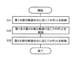
- the control unit 50 calculates (S31) a control command for the robot 2 according to only the first partial trajectory that was first divided by the trajectory division process (S2) in calculating the control command using the learned control model 30. For example, during the period when the robot 2 starts to move, coordinate data corresponding to only the first partial trajectory of the trajectory divided into the control model 30 is input. In this case, when the inference results from the control models corresponding to each partial trajectory are integrated in the control model 30 to obtain the final output, the weight of the inference results of the control models corresponding to the other partial trajectories becomes close to "0", so that the robot 2 can be controlled according to only the first partial trajectory.
- the control unit 50 calculates control commands for the robot 2 according to both the first partial trajectory and the second partial trajectory divided following the first partial trajectory (S32). For example, if the coordinate data of the robot 2 input to the control model 30 indicates coordinates near the middle of the first and second partial trajectories, the outputs of the two control models in the control model 30 corresponding to each partial trajectory are both weighted so as to be reflected in the final output. In this way, the system 1 can reflect the learning results of the control model 30 based on a trajectory divided so as to have an overlapping portion between two adjacent partial trajectories in the operation of the robot 2.
- the control unit 50 calculates a control command for the robot 2 according to only the second partial trajectory, similar to the control according to the first partial trajectory in step S31 (S33). For example, if the control model 30 has been trained to move the robot 2 according to three or more partial trajectories, the control unit 50 may repeat the same processing from step S32 onwards according to the coordinate data resulting from the movement of the robot 2. The control unit 50 then ends the processing of this flowchart.
- control model 30 trained using the divided trajectories including overlaps can control the robot 2 so that the operation stages corresponding to each partial trajectory after division gradually change (S31 to S33).
- the above process may be performed by a control model trained by a method other than machine learning according to multiple partial trajectories that have overlaps, for example.
- the terminal device 5 in this embodiment is an example of an information processing device that controls machine learning to make the robot 2 perform a predetermined operation.
- the terminal device 5 includes a display unit 54 that displays information, an operation unit 53 (an example of an input unit) that accepts a user's operation, and a control unit 50 that controls the display unit 54 and the operation unit 53.
- the control unit 50 causes the display unit 54 to display a trajectory indicating the movement of the robot 2 in a predetermined operation (S13).
- the control unit 50 accepts a user operation on the trajectory displayed on the display unit 54 in the operation unit 53 (S14, S19), and sets a plurality of partial trajectories that divide the trajectory (S17, S18, S20).
- the control unit 50 updates the control model 30 by machine learning (S21).
- the terminal device 5 With the terminal device 5 as described above, while the trajectory of the robot 2 is displayed (S13), a user operation such as selection of a partial trajectory is accepted (S14, S19), and multiple partial trajectories that divide the trajectory so as to overlap each other are set (S17, S18, S20).
- the terminal device 5 updates the control model 30 by machine learning so as to cause the robot 2 to perform a predetermined operation according to the set partial trajectories (S21). This makes it easier for the robot 2 to learn to operate with precision, such as by smoothing the transition from one partial trajectory to the next partial trajectory, in a predetermined operation by the control model 30 of the robot 2.
- control unit 50 controls the machine learning so that the robot 2 performs a plurality of partial actions, each of which corresponds to a partial trajectory set in a predetermined action, according to the set partial trajectory (S21). This allows, for example, the control model 30 of the robot 2 to machine learn a different action for each partial trajectory.
- control unit 50 detects whether multiple partial trajectories partially overlap each other based on the partial trajectories input in the partial trajectory selection operation (an example of a user operation) (S16). This makes it easier to set partial trajectories that divide trajectories so that they overlap each other, such as by executing a predetermined operation to make the partial trajectories overlap when, for example, two input partial trajectories do not overlap (S19, S20).
- control unit 50 when the control unit 50 detects that the multiple partial trajectories do not overlap with each other (NO in S16), it sets the multiple partial trajectories so that each partial trajectory partially overlaps with an adjacent partial trajectory (S20). This makes it possible to automatically generate overlapping parts even if the adjacent partial trajectories input by the user operation do not have overlapping parts.
- the control unit 50 accepts an input operation of a lower limit of overlap time on the operation unit 53 as an example of a user operation for setting a lower limit of the amount of overlap indicating the degree to which multiple partial trajectories overlap with each other (S19).
- the control unit 50 extends each partial trajectory as an example of setting multiple partial trajectories so as to increase the overlap time to or above the lower limit (S20). This allows, for example, a user to input a lower limit of the overlap time etc. according to the task of the operation to be learned by the robot 2, and adjust the length of the overlapping portion.
- the control unit 50 assigns attribute information D2 that distinguishes the multiple partial trajectories from each other to each partial trajectory set by the partial trajectory selection operation (an example of a user operation) (S17).
- the control unit 50 causes the display unit 54 to display the attribute information D2 assigned to each partial trajectory so as to indicate that multiple pieces of attribute information D2 have been assigned to the overlapping parts of the trajectory where the multiple partial trajectories overlap (S17, see FIG. 4).
- the terminal device 5 can manage the set partial trajectories using the attribute information D2.
- control unit 50 controls the machine learning to make the robot 2 perform a predetermined operation according to the attribute information D2 assigned to the multiple partial trajectories (S21). According to the results of such machine learning, the robot 2 can be controlled to operate with high precision according to the attribute information D2 assigned to the partial trajectories that divide the trajectory so as to overlap with each other, for example.
- the display unit 54 displays the movement direction of the robot 2 in a specified operation after machine learning (S13, S22).
- the control unit 50 updates the display of the movement direction on the display unit 54 as a result of controlling the machine learning according to the partial trajectory set by user operation (S22). This makes it possible to provide feedback to the user on how the movement direction of the robot 2 in a specified operation after machine learning has changed as a result of updating the control model 30 by machine learning according to the partial trajectory set by user operation (S21), for example.
- control unit 50 acquires coordinate data x(t) for each time that indicates the movement of the robot 2 by direct teaching as a trajectory (S11). This allows, for example, a user to intuitively teach the robot 2 the general movements. Also, in this embodiment, the control unit 50 may acquire coordinate data for each time that indicates the movement of the robot 2 by remote control as a trajectory. This makes it easier to safely teach the robot 2 the movements, for example, by avoiding contact between the robot 2 and the user.
- control unit 50 uses machine learning to train a control model 30 that controls the movement of the robot 2 in accordance with multiple partial trajectories set by user operation (S21).
- the control unit 50 sequentially inputs coordinate data x(t), which is an example of the position or posture at which the robot 2 moves, to the control model 30 so that the robot 2 performs a predetermined movement, and outputs behavioral data y(t) as a control command for moving the robot 2.
- coordinate data x(t) which is an example of the position or posture at which the robot 2 moves
- behavioral data y(t) as a control command for moving the robot 2.
- the behavior data y(t) as a control command output by the control model 30 from coordinate data x(t), which is an example of an input position or posture includes a mean value and a variance value that define the probability distribution of the relative displacement from the coordinates indicated by the input coordinate data x(t) to the target coordinates for operating the robot 2 (see formula (4)).
- the control command by such a control model 30 can be determined to one value, for example, depending on the mean value and the variance value.
- the trajectory division process (S2) in this embodiment provides an information processing method for controlling machine learning to make the robot 2 perform a predetermined operation.
- This method is executed by the control unit 50 of the terminal device 5 (an example of a computer) that controls the display unit 54 that displays information and the operation unit 53 (an example of an input unit) that accepts user operations.
- the control unit 50 causes the display unit 54 to display a trajectory indicating the movement of the robot 2 in a predetermined operation (S13, S21).
- the control unit 50 accepts user operations related to the trajectory displayed on the display unit 54 in the operation unit 53 (S14, S19) and sets multiple partial trajectories that divide the trajectory (S17, S18, S20).
- the control unit 50 updates the control model 30 by machine learning (S21) as an example of controlling machine learning to make the robot 2 perform a predetermined operation for each partial trajectory according to the partial trajectory set by the user operation.
- a program is provided for causing the control unit 50 of the terminal device 5, which is an example of a computer, to execute the information processing method described above.
- the information processing method and program described above make it easier for the robot 2 to learn to operate with high precision.
- the terminal device 5 of this embodiment is an example of a control device that causes the robot 2 to perform a predetermined operation.
- the terminal device 5 includes a communication I/F 52 (an example of a communication unit) that performs data communication with external devices such as the robot control device 4, and a control unit 50 that controls the robot 2 by data communication via the communication I/F 52 (see S3 in FIG. 5).
- a plurality of partial trajectories are set by dividing a trajectory showing the movement of the robot 2 in a predetermined operation, for example, by trajectory data D1 divided according to attribute information D2.
- the plurality of partial trajectories include a first partial trajectory and a second partial trajectory that are adjacent to each other in the trajectory of the robot 2.
- the first and second partial trajectories have an overlapping portion where the first and second partial trajectories overlap, a first independent portion of only the first partial trajectory, and a second independent portion of only the second partial trajectory (see FIG. 4).
- the control unit 50 causes the robot 2 to perform a predetermined operation according to both the first and second partial trajectories (S32).
- the robot 2 is controlled according to both partial trajectories (S32).
- S32 partial trajectories
- the control device of the present disclosure is not limited to the above example, and may be realized, for example, by the robot control device 4, or by both the robot control device 4 and the terminal device 5.
- control unit 50 causes the robot 2 to perform a predetermined operation in the first independent portion according to the first partial trajectory (S31), and causes the robot 2 to perform a predetermined operation in the second independent portion according to the second partial trajectory (S33). This makes it easier to operate the robot 2 with high precision for each stage of the operation corresponding to each partial trajectory, for example, in accordance with only each partial trajectory other than the overlapping portion of the multiple partial trajectories.
- the terminal device 5 further includes an operation unit 53 (an example of an information input unit, see S14 and S19 in FIG. 6) that inputs information about the multiple partial trajectories, and a control unit 50 (an example of a learning unit, see S2 in FIG. 5) that performs machine learning to make the robot 2 perform a predetermined operation based on the multiple partial trajectories set by the information input from the operation unit 53 (see S17).
- the control unit 50 performs machine learning according to the first independent portion, the overlapping portion, and the second independent portion in the first and second partial trajectories (S21).
- control model 30 that has been trained by such machine learning, it is possible to make the robot 2 perform a predetermined operation according to each portion in the first and second partial trajectories (S31 to S33), making it easier to operate the robot 2 with high accuracy.
- the terminal device 5 further includes an information processing unit that controls machine learning to make the robot 2 perform a predetermined operation.
- the control unit 50 is an example of the information processing unit in this embodiment.
- the control unit 50 displays a trajectory showing the movement of the robot 2 in a predetermined operation on the display unit 54 that displays information (S13, S21).
- the control unit 50 accepts a user operation on the trajectory displayed on the display unit 54 in the operation unit 53, which is an example of an input unit that accepts user operations (S14, S19), and sets multiple partial trajectories that divide the trajectory (S17, S18, S20).
- the control unit 50 updates the control model 30 by machine learning (S21), as an example of controlling machine learning to make the robot 2 perform a predetermined operation for each partial trajectory according to the partial trajectory set by the user operation.
- the control unit 50 controls the robot 2 according to the results of the machine learning controlled by the control unit 50 (S31 to S33). This makes it possible to set a plurality of partial trajectories that overlap each other at adjacent portions on the trajectory along which the robot 2 moves in a predetermined operation, making it easier to operate the robot 2 with high accuracy.
- control system 1 including the terminal device 5 as described above causes the robot 2 to perform a predetermined operation.
- FIG. 11 is a diagram showing an example of display in the trajectory division process in the terminal device 5 of embodiment 2. Similar to the example of FIG. 7(A), FIG. 11 shows an example in which the first partial trajectory is selected by a user operation in the trajectory division process.
- the terminal device 5 of this embodiment displays a marker 60 on the display unit 54 in addition to the trajectory of the robot 2 and the arrow Vt indicating the movement direction.
- the marker 60 indicates a position where the robot 2 has been stopped for a relatively long predetermined period of time, for example, during direct teaching by the user.
- the robot 2 may temporarily stop due to a change in direction, etc. For example, by displaying the marker 60, it is possible to make it easier for the user to recognize such portions of the trajectory where the operation of the robot 2 changes. This allows, for example, the user to input a selection operation of a partial trajectory by referring to the marker 60, making it easier to divide the trajectory according to the change in the operation of the robot 2.
- FIG. 12 is a flowchart illustrating the trajectory division process in the terminal device 5 of this embodiment.
- the control unit 50 of the terminal device 5 executes a process (S30) for displaying the marker 60 in addition to processes similar to steps S11-S12 and S14-S21 in the trajectory division process (FIG. 6) of embodiment 1.
- the control unit 50 executes processes (S13A, S22A) for further displaying the marker 60 instead of steps S13 and S22 in FIG. 6.
- the control unit 50 learns the control model 30 based on the acquired trajectory data D1 (S12), and then identifies the time when the robot 2 was stopped for a predetermined period (e.g., 3 seconds) from the coordinates for each time in the trajectory data D1 (S30).
- the predetermined period for identifying such a pause time is set, for example, as a period during which the robot 2 is assumed to be paused when switching between operations.
- the control unit 50 causes the display unit 54 to display, for example, the trajectory of the robot 2 according to the trajectory data D1, an arrow Vt indicating the direction of movement by the control model 30, and a marker 60 indicating the coordinates on the trajectory at the identified pause time (S13).
- the display unit 54 displays the markers 60 at two points on the trajectory.
- control unit 50 displays the same display as in step S22, and also displays the marker 60 based on the pause time identified in step S30 (S22A).
- the display unit 54 displays the marker 60 according to the time when the robot 2 pauses together with the trajectory of the robot 2 (S30, S13A, S22A). This makes it possible to display the marker 60 at the position where the robot 2 pauses due to a change in operation, for example, and to easily select a partial trajectory such as dividing the trajectory according to the marker 60.
- a pause time is identified based on the trajectory data D1 of the robot 2, and the marker 60 is displayed to indicate the coordinates on the trajectory at that time.
- the marker 60 is not limited to such a pause time.
- the marker 60 may be displayed according to a time specified by the user by pressing a specific button or the like on the controller by storing the time in association with the trajectory data D1.
- the control unit 50 displays a marker indicating a location on the trajectory displayed on the display unit 54 where the trajectory meets a predetermined condition corresponding to a change in the movement of the robot 2 (S13A, S22A).
- the predetermined condition includes, for example, a pause time corresponding to a change in the movement of the robot 2, and a time designated by the user when performing direct teaching, etc.
- a marker 60 can be displayed on a GUI for dividing the trajectory of the robot 2, making it easier for the user to confirm the points in the trajectory of the robot 2 where phases or the like change in response to changes in the movement.
- the terminal device 5 detects overlapping parts between two partial trajectories in the trajectory division process (FIGS. 6 and 12), and if there are no overlapping parts (NO in S16), automatically expands each partial trajectory (S20).
- the terminal device 5 may prompt the user to select an overlapping partial trajectory by not accepting the partial trajectory selection operation.
- the terminal device 5 of this embodiment does not need to detect overlapping parts, and for example, when accepting the partial trajectory selection operation (S14), may display an indication on the display unit 54 prompting the user to select a partial trajectory that overlaps with the previously selected partial trajectory.
- control model 30 is not limited to Gaussian process regression.
- the control model for each partial trajectory may be realized by a neural network, or may be learned by supervised learning using the behavioral data in the trajectory data D1 as teacher data.
- learning of the control model is not limited to machine learning such as supervised learning, and various methods for making the robot 2 learn movements based on the trajectory data D1 can be used.
- the control model may learn a trajectory using Dynamic Movement Primitives (DMP).
- DMP Dynamic Movement Primitives
- attribute information D2 may be added to the input information to one control model, so that the behavior of the control model changes depending on the attribute information D2.
- attribute information D2 may be added to the input information to one control model, so that the behavior of the control model changes depending on the attribute information D2.
- control system 1 causes the robot 2 to perform an operation of inserting the connector 6 into the socket 7, as shown in FIG. 1.
- the operation that the control system 1 causes the robot 2 to perform is not limited to the above example, and may be various operations that generate a trajectory of the robot 2.
- control system 1 is applicable to the control of various robots that perform various operations, and is not limited to the robot 2 as exemplified in FIG. 1.
- the terminal device 5 displays the trajectory of the robot 2 in relation to the X-axis and Y-axis, as shown in FIG. 4, for example.
- the terminal device 5 of this embodiment may also display the trajectory using a time axis, such as the relationship between the X-axis and the time axis.
- the components described in the attached drawings and detailed description may include not only components essential for solving the problem, but also components that are not essential for solving the problem in order to illustrate the above technology. Therefore, just because these non-essential components are described in the attached drawings or detailed description, it should not be immediately determined that these non-essential components are essential.
- a first aspect of the present disclosure is a control device that causes a robot to perform a predetermined operation.
- the control device includes a communication unit that performs data communication with an external device, and a control unit that controls the robot by data communication via the communication unit.
- a plurality of partial trajectories are set by dividing a trajectory that indicates the movement of the robot in a predetermined operation.
- the plurality of partial trajectories include a first partial trajectory and a second partial trajectory that are adjacent to each other in the trajectory.
- the first and second partial trajectories have an overlapping portion where the first and second partial trajectories overlap, a first independent portion that is only the first partial trajectory, and a second independent portion that is only the second partial trajectory.
- the control unit causes the robot to perform a predetermined operation in accordance with both the first and second partial trajectories.
- control unit causes the robot to perform a predetermined operation in the first independent portion according to the first partial trajectory, and causes the robot to perform a predetermined operation in the second independent portion according to the second partial trajectory.
- control device of the first or second aspect further includes an information input unit that inputs information about the multiple partial trajectories, and a learning unit that performs machine learning to make the robot perform a predetermined operation based on the multiple partial trajectories set by the information input from the information input unit.
- the learning unit performs machine learning according to the first independent portion, the overlapping portion, and the second independent portion in the first and second partial trajectories.
- control device of any one of the first to third aspects further includes an information processing unit that controls machine learning to make the robot perform a predetermined operation.
- the information processing unit displays a trajectory showing the movement of the robot in the predetermined operation on a display unit that displays information.
- the information processing unit in an input unit that accepts user operations, accepts a user operation related to the trajectory displayed on the display unit and sets multiple partial trajectories that divide the trajectory.
- the information processing unit controls machine learning to make the robot perform a predetermined operation such that the robot performs the predetermined operation for each partial trajectory according to the partial trajectory set by the user operation.
- the partial trajectories set as the multiple partial trajectories that divide the trajectory overlap each other in adjacent portions of the trajectory.
- the control unit controls the robot according to the result of the machine learning controlled by the information processing unit.
- a fifth aspect of the present disclosure is an information processing device that controls machine learning to make a robot perform a predetermined operation.
- the information processing device includes a display unit that displays information, an input unit that accepts user operations, and a control unit that controls the display unit and the input unit.
- the control unit causes the display unit to display a trajectory showing the movement of the robot in the predetermined operation.
- the control unit accepts, in the input unit, a user operation related to the trajectory displayed on the display unit, and sets multiple partial trajectories that divide the trajectory.
- the control unit controls the machine learning to make the robot perform a predetermined operation for each partial trajectory according to the partial trajectory set by the user operation.
- the partial trajectories set as multiple partial trajectories that divide the trajectory overlap each other in adjacent portions of the trajectory.
- control unit controls the machine learning so that the robot performs a plurality of partial actions, each of which corresponds to the partial trajectory set in a predetermined action, in accordance with the partial trajectory set.
- control unit detects whether multiple partial trajectories partially overlap with each other based on partial trajectories input by user operation.
- control unit when the control unit detects that the multiple partial trajectories do not partially overlap each other, the control unit sets the multiple partial trajectories so that each partial trajectory partially overlaps with an adjacent partial trajectory.
- the control unit receives a user operation at the input unit to set a lower limit value of the amount of overlap indicating the degree to which the multiple partial trajectories overlap each other, and if the amount of overlap in the multiple partial trajectories falls below the lower limit value, sets the multiple partial trajectories so as to increase the amount of overlap to or above the lower limit value.
- the control unit assigns attribute information to each partial trajectory set by a user operation, which distinguishes the multiple partial trajectories from each other, and causes the display unit to display the attribute information assigned to each partial trajectory so as to indicate that multiple pieces of attribute information have been assigned to portions of the trajectory where the multiple partial trajectories overlap each other.
- control unit controls machine learning to make the robot perform a predetermined action according to attribute information assigned to a plurality of partial trajectories.
- the control unit causes the display unit to display each of the multiple partial trajectories in a different manner according to the attribute information assigned to each of the multiple partial trajectories, and at locations where the multiple partial trajectories overlap each other, causes the partial trajectories to be displayed superimposed in a manner according to their respective attribute information.
- the display unit displays the movement direction of the robot in a predetermined operation after machine learning
- the control unit updates the display of the movement direction on the display unit as a result of controlling the machine learning according to the partial trajectory set by a user operation.
- control unit acquires coordinate data for each time point that indicates the movement of the robot by direct teaching as a trajectory.
- control unit displays a marker indicating a location on the trajectory displayed on the display unit where the trajectory meets a predetermined condition corresponding to a change in the robot's movement.
- the control unit uses machine learning to train a control model that controls the movement of the robot in accordance with a plurality of partial trajectories set by user operation, and sequentially inputs the positions or postures at which the robot will move to the control model so as to cause the robot to perform a predetermined movement, and outputs a control command to cause the robot to move.
- the control command output from the position or posture input by the control model includes a mean value and a variance value that define the probability distribution of the relative displacement to the target coordinates that operate the robot at the input position or posture.
- a nineteenth aspect of the present disclosure is an information processing method for controlling machine learning to cause a robot to perform a predetermined operation.
- a control unit of a computer that controls a display unit that displays information and an input unit that accepts user operations controls the machine learning to cause the display unit to display a trajectory showing the movement of the robot in a predetermined operation, accepts user operations in the input unit to set multiple partial trajectories that divide the trajectory displayed on the display unit, and controls the machine learning to cause the robot to perform the predetermined operation for each partial trajectory according to the partial trajectory set by the user operation.
- a twentieth aspect of the present disclosure is a program for causing a control unit of a computer to execute the information processing method of the nineteenth aspect.
- a twenty-first aspect of the present disclosure is a control method for making a robot perform a predetermined operation.
- a plurality of partial trajectories are set by dividing a trajectory showing the movement of the robot in the predetermined operation.
- the plurality of partial trajectories include a first partial trajectory and a second partial trajectory that are adjacent to each other in the trajectory.
- the first and second partial trajectories have an overlapping portion where the first and second partial trajectories overlap, a first independent portion of only the first partial trajectory, and a second independent portion of only the second partial trajectory.
- the control unit makes the robot perform the predetermined operation in accordance with both the first and second partial trajectories.
- control unit causes the robot to perform a predetermined operation in the first independent portion according to the first partial trajectory, and causes the robot to perform a predetermined operation in the second independent portion according to the second partial trajectory.
- a learning unit of a computer that performs machine learning to make a robot performs a predetermined operation based on a plurality of partial trajectories set by information input from an input unit that inputs information about the plurality of partial trajectories performs machine learning according to the first independent portion, the overlapping portion, and the second independent portion in the first and second partial trajectories.
- This disclosure is applicable to various control systems that cause robots to perform specific operations.
Landscapes
- Engineering & Computer Science (AREA)
- Physics & Mathematics (AREA)
- General Physics & Mathematics (AREA)
- Automation & Control Theory (AREA)
- Robotics (AREA)
- Mechanical Engineering (AREA)
- Human Computer Interaction (AREA)
- Manufacturing & Machinery (AREA)
- Manipulator (AREA)
Abstract
Priority Applications (1)
| Application Number | Priority Date | Filing Date | Title |
|---|---|---|---|
| JP2025531493A JPWO2025009420A1 (fr) | 2023-07-05 | 2024-06-21 |
Applications Claiming Priority (2)
| Application Number | Priority Date | Filing Date | Title |
|---|---|---|---|
| JP2023-110784 | 2023-07-05 | ||
| JP2023110784 | 2023-07-05 |
Publications (1)
| Publication Number | Publication Date |
|---|---|
| WO2025009420A1 true WO2025009420A1 (fr) | 2025-01-09 |
Family
ID=94172078
Family Applications (1)
| Application Number | Title | Priority Date | Filing Date |
|---|---|---|---|
| PCT/JP2024/022660 Ceased WO2025009420A1 (fr) | 2023-07-05 | 2024-06-21 | Dispositif de commande, dispositif de traitement d'informations et procédé |
Country Status (2)
| Country | Link |
|---|---|
| JP (1) | JPWO2025009420A1 (fr) |
| WO (1) | WO2025009420A1 (fr) |
Citations (7)
| Publication number | Priority date | Publication date | Assignee | Title |
|---|---|---|---|---|
| JPH09297611A (ja) * | 1996-05-02 | 1997-11-18 | Nippon Telegr & Teleph Corp <Ntt> | ロボット教示方法及び装置 |
| JP2005135095A (ja) * | 2003-10-29 | 2005-05-26 | Kawasaki Heavy Ind Ltd | ロボット動作データ作成装置 |
| JP2010067033A (ja) * | 2008-09-11 | 2010-03-25 | Sony Corp | データ処理装置、データ処理方法、及び、プログラム |
| WO2016103307A1 (fr) | 2014-12-26 | 2016-06-30 | 川崎重工業株式会社 | Procédé permettant de générer un programme de fonctionnement de robot et dispositif permettant de générer un programme de fonctionnement de robot |
| WO2018042704A1 (fr) * | 2016-09-02 | 2018-03-08 | 三菱電機株式会社 | Dispositif de génération de valeur d'instruction |
| JP2019126861A (ja) * | 2018-01-23 | 2019-08-01 | セイコーエプソン株式会社 | 教示装置、ロボット制御装置、ロボット、及びロボットシステム |
| US20200230817A1 (en) * | 2017-02-03 | 2020-07-23 | Doosan Robotics Inc | Skill-based robot programming apparatus and method |
-
2024
- 2024-06-21 JP JP2025531493A patent/JPWO2025009420A1/ja active Pending
- 2024-06-21 WO PCT/JP2024/022660 patent/WO2025009420A1/fr not_active Ceased
Patent Citations (7)
| Publication number | Priority date | Publication date | Assignee | Title |
|---|---|---|---|---|
| JPH09297611A (ja) * | 1996-05-02 | 1997-11-18 | Nippon Telegr & Teleph Corp <Ntt> | ロボット教示方法及び装置 |
| JP2005135095A (ja) * | 2003-10-29 | 2005-05-26 | Kawasaki Heavy Ind Ltd | ロボット動作データ作成装置 |
| JP2010067033A (ja) * | 2008-09-11 | 2010-03-25 | Sony Corp | データ処理装置、データ処理方法、及び、プログラム |
| WO2016103307A1 (fr) | 2014-12-26 | 2016-06-30 | 川崎重工業株式会社 | Procédé permettant de générer un programme de fonctionnement de robot et dispositif permettant de générer un programme de fonctionnement de robot |
| WO2018042704A1 (fr) * | 2016-09-02 | 2018-03-08 | 三菱電機株式会社 | Dispositif de génération de valeur d'instruction |
| US20200230817A1 (en) * | 2017-02-03 | 2020-07-23 | Doosan Robotics Inc | Skill-based robot programming apparatus and method |
| JP2019126861A (ja) * | 2018-01-23 | 2019-08-01 | セイコーエプソン株式会社 | 教示装置、ロボット制御装置、ロボット、及びロボットシステム |
Non-Patent Citations (2)
| Title |
|---|
| G. FRANZESEA. MESZAROSL. PETERNELJ. KOBER: "ILoSA: Interactive learning of stiffness and attractor", IROS, 2021 |
| G. FRANZESEA. MESZAROSL. PETERNELJ. KOBER: "ILoSA: Interactive learning of stiffness and attractors", IROS, 2021 |
Also Published As
| Publication number | Publication date |
|---|---|
| JPWO2025009420A1 (fr) | 2025-01-09 |
Similar Documents
| Publication | Publication Date | Title |
|---|---|---|
| US9387589B2 (en) | Visual debugging of robotic tasks | |
| Pan et al. | Augmented reality-based robot teleoperation system using RGB-D imaging and attitude teaching device | |
| US11235461B2 (en) | Controller and machine learning device | |
| US11007646B2 (en) | Programming assistance apparatus, robot system, and method for generating program | |
| JP5939202B2 (ja) | ロボット教示補助装置、ロボットシステムおよびロボット教示方法 | |
| JP7427113B2 (ja) | ロボットデモンストレーション学習用スキルテンプレート | |
| Field et al. | Learning trajectories for robot programing by demonstration using a coordinated mixture of factor analyzers | |
| JP4137909B2 (ja) | ロボットプログラム補正装置 | |
| KR20170024769A (ko) | 로봇 제어 장치 | |
| JP6796557B2 (ja) | 溶接ロボットのトーチケーブル干渉評価情報出力装置、評価情報出力方法及びプログラム | |
| JP6625266B1 (ja) | ロボット制御装置 | |
| JP2005063375A (ja) | 仮想ユーザを用いた操作性評価処理システム | |
| JP5938780B2 (ja) | 動作指令装置、動作指令方法及び動作パターン作成装置 | |
| CN117621041A (zh) | 生成机器人的动作路径的装置、方法以及记录介质 | |
| JP2024034217A (ja) | ロボットの動作経路を生成する装置、方法およびプログラム | |
| WO2025009420A1 (fr) | Dispositif de commande, dispositif de traitement d'informations et procédé | |
| TWI847257B (zh) | 機器人示教系統 | |
| EP4431252A1 (fr) | Dispositif de commande de robot, système de robot et procédé de commande de robot | |
| US11975454B2 (en) | Program generation device and non-transitory computer-readable storage medium storing program | |
| CN118322214A (zh) | 基于单次示教的机械臂模仿学习方法及装置 | |
| WO2020075834A1 (fr) | Dispositif de simulation, procédé de simulation et programme de simulation | |
| CN116442218A (zh) | 一种遥操作跟踪方法、装置、设备、系统及存储介质 | |
| CN117561146A (zh) | 优化辅助装置 | |
| JP2021041511A (ja) | ロボットハンドの動作教示装置 | |
| WO2024253174A1 (fr) | Dispositif de génération de données d'apprentissage, dispositif de commande de robot, système de commande de robot et procédé de génération de données d'apprentissage |
Legal Events
| Date | Code | Title | Description |
|---|---|---|---|
| 121 | Ep: the epo has been informed by wipo that ep was designated in this application |
Ref document number: 24835933 Country of ref document: EP Kind code of ref document: A1 |
|
| ENP | Entry into the national phase |
Ref document number: 2025531493 Country of ref document: JP Kind code of ref document: A |
|
| WWE | Wipo information: entry into national phase |
Ref document number: 2025531493 Country of ref document: JP |
|
| WWE | Wipo information: entry into national phase |
Ref document number: 2024835933 Country of ref document: EP |
|
| NENP | Non-entry into the national phase |
Ref country code: DE |
|
| ENP | Entry into the national phase |
Ref document number: 2024835933 Country of ref document: EP Effective date: 20260205 |