WO2025023038A1 - 鉄基結晶合金の製造方法 - Google Patents
鉄基結晶合金の製造方法 Download PDFInfo
- Publication number
- WO2025023038A1 WO2025023038A1 PCT/JP2024/025071 JP2024025071W WO2025023038A1 WO 2025023038 A1 WO2025023038 A1 WO 2025023038A1 JP 2024025071 W JP2024025071 W JP 2024025071W WO 2025023038 A1 WO2025023038 A1 WO 2025023038A1
- Authority
- WO
- WIPO (PCT)
- Prior art keywords
- iron
- alloy
- less
- phase
- molten
- Prior art date
- Legal status (The legal status is an assumption and is not a legal conclusion. Google has not performed a legal analysis and makes no representation as to the accuracy of the status listed.)
- Pending
Links
Classifications
-
- C—CHEMISTRY; METALLURGY
- C22—METALLURGY; FERROUS OR NON-FERROUS ALLOYS; TREATMENT OF ALLOYS OR NON-FERROUS METALS
- C22C—ALLOYS
- C22C45/00—Amorphous alloys
- C22C45/02—Amorphous alloys with iron as the major constituent
-
- B—PERFORMING OPERATIONS; TRANSPORTING
- B22—CASTING; POWDER METALLURGY
- B22D—CASTING OF METALS; CASTING OF OTHER SUBSTANCES BY THE SAME PROCESSES OR DEVICES
- B22D11/00—Continuous casting of metals, i.e. casting in indefinite lengths
- B22D11/06—Continuous casting of metals, i.e. casting in indefinite lengths into moulds with travelling walls, e.g. with rolls, plates, belts, caterpillars
- B22D11/0611—Continuous casting of metals, i.e. casting in indefinite lengths into moulds with travelling walls, e.g. with rolls, plates, belts, caterpillars formed by a single casting wheel, e.g. for casting amorphous metal strips or wires
-
- C—CHEMISTRY; METALLURGY
- C22—METALLURGY; FERROUS OR NON-FERROUS ALLOYS; TREATMENT OF ALLOYS OR NON-FERROUS METALS
- C22C—ALLOYS
- C22C38/00—Ferrous alloys, e.g. steel alloys
- C22C38/002—Ferrous alloys, e.g. steel alloys containing In, Mg, or other elements not provided for in one single group C22C38/001 - C22C38/60
-
- C—CHEMISTRY; METALLURGY
- C22—METALLURGY; FERROUS OR NON-FERROUS ALLOYS; TREATMENT OF ALLOYS OR NON-FERROUS METALS
- C22C—ALLOYS
- C22C38/00—Ferrous alloys, e.g. steel alloys
- C22C38/10—Ferrous alloys, e.g. steel alloys containing cobalt
-
- H—ELECTRICITY
- H01—ELECTRIC ELEMENTS
- H01F—MAGNETS; INDUCTANCES; TRANSFORMERS; SELECTION OF MATERIALS FOR THEIR MAGNETIC PROPERTIES
- H01F1/00—Magnets or magnetic bodies characterised by the magnetic materials therefor; Selection of materials for their magnetic properties
- H01F1/01—Magnets or magnetic bodies characterised by the magnetic materials therefor; Selection of materials for their magnetic properties of inorganic materials
- H01F1/03—Magnets or magnetic bodies characterised by the magnetic materials therefor; Selection of materials for their magnetic properties of inorganic materials characterised by their coercivity
- H01F1/12—Magnets or magnetic bodies characterised by the magnetic materials therefor; Selection of materials for their magnetic properties of inorganic materials characterised by their coercivity of soft-magnetic materials
- H01F1/14—Magnets or magnetic bodies characterised by the magnetic materials therefor; Selection of materials for their magnetic properties of inorganic materials characterised by their coercivity of soft-magnetic materials metals or alloys
- H01F1/147—Alloys characterised by their composition
- H01F1/153—Amorphous metallic alloys, e.g. glassy metals
- H01F1/15308—Amorphous metallic alloys, e.g. glassy metals based on Fe/Ni
-
- H—ELECTRICITY
- H01—ELECTRIC ELEMENTS
- H01F—MAGNETS; INDUCTANCES; TRANSFORMERS; SELECTION OF MATERIALS FOR THEIR MAGNETIC PROPERTIES
- H01F1/00—Magnets or magnetic bodies characterised by the magnetic materials therefor; Selection of materials for their magnetic properties
- H01F1/01—Magnets or magnetic bodies characterised by the magnetic materials therefor; Selection of materials for their magnetic properties of inorganic materials
- H01F1/03—Magnets or magnetic bodies characterised by the magnetic materials therefor; Selection of materials for their magnetic properties of inorganic materials characterised by their coercivity
- H01F1/12—Magnets or magnetic bodies characterised by the magnetic materials therefor; Selection of materials for their magnetic properties of inorganic materials characterised by their coercivity of soft-magnetic materials
- H01F1/14—Magnets or magnetic bodies characterised by the magnetic materials therefor; Selection of materials for their magnetic properties of inorganic materials characterised by their coercivity of soft-magnetic materials metals or alloys
- H01F1/147—Alloys characterised by their composition
- H01F1/153—Amorphous metallic alloys, e.g. glassy metals
- H01F1/15341—Preparation processes therefor
-
- B—PERFORMING OPERATIONS; TRANSPORTING
- B22—CASTING; POWDER METALLURGY
- B22D—CASTING OF METALS; CASTING OF OTHER SUBSTANCES BY THE SAME PROCESSES OR DEVICES
- B22D11/00—Continuous casting of metals, i.e. casting in indefinite lengths
- B22D11/16—Controlling or regulating processes or operations
-
- C—CHEMISTRY; METALLURGY
- C21—METALLURGY OF IRON
- C21D—MODIFYING THE PHYSICAL STRUCTURE OF FERROUS METALS; GENERAL DEVICES FOR HEAT TREATMENT OF FERROUS OR NON-FERROUS METALS OR ALLOYS; MAKING METAL MALLEABLE, e.g. BY DECARBURISATION OR TEMPERING
- C21D1/00—General methods or devices for heat treatment, e.g. annealing, hardening, quenching or tempering
- C21D1/26—Methods of annealing
-
- C—CHEMISTRY; METALLURGY
- C21—METALLURGY OF IRON
- C21D—MODIFYING THE PHYSICAL STRUCTURE OF FERROUS METALS; GENERAL DEVICES FOR HEAT TREATMENT OF FERROUS OR NON-FERROUS METALS OR ALLOYS; MAKING METAL MALLEABLE, e.g. BY DECARBURISATION OR TEMPERING
- C21D6/00—Heat treatment of ferrous alloys
- C21D6/007—Heat treatment of ferrous alloys containing Co
Definitions
- Such materials include iron-based amorphous materials and iron-based nanocrystalline materials, whose main raw materials are iron (Fe), silicon (Si), and boron (B).
- Fe-Si-B amorphous alloy ribbons with a thickness of about 17 to 25 ⁇ m, which are produced using such soft magnetic materials by the molten metal rapid solidification method, is growing as an alternative to conventional silicon steel sheets, mainly for use in large transformers and inductors.
- Fe-Si-B amorphous alloy ribbons mentioned above have lower core loss than silicon steel sheets, it is being considered to take advantage of this feature and apply them to the rotor and stator cores of brushless direct current (BLDC) motors to improve motor efficiency.
- BLDC brushless direct current
- high motor efficiency can be obtained as the operating range of the soft magnetic material is in the high-frequency band of around 2 kHz, so it is expected that they will be used in white goods such as vacuum cleaners and auxiliary motors for electrical equipment, which require high-speed motor rotation.
- BLDC motors for driving EVs in the tens of kW class or more have been made more efficient by combining silicon steel core material with anisotropic rare earth iron boron sintered magnets, which have excellent permanent magnetic properties, and utilizing magnet torque.
- silicon steel which has low magnetic permeability, cannot fully utilize the excellent magnetic properties of anisotropic rare earth iron boron sintered magnets, making it difficult to achieve a low iron loss core material. For this reason, there is extremely high market demand for high-output, high-efficiency BLDC motors that can contribute to energy savings in automobiles through the synergistic effect of effectively utilizing permanent magnet performance and reducing iron loss in the core material.
- Fe-Si-B amorphous alloys have a higher magnetic permeability than silicon steel sheets and can reduce iron loss to about one-tenth of that of silicon steel sheets, so they are being considered as a replacement for silicon steel sheets as a core material for BLDC motors for driving EVs.
- Bs saturation magnetic flux density
- Fe-Si-B amorphous alloy ribbons are thin, at about 25 ⁇ m, and it is difficult to perform punching press processing to manufacture laminated cores for rotor cores and stator cores of BLDC motors, so their use is limited mainly to wound cores, making it difficult to replace silicon steel sheets in motor applications.
- Fe-Si-B nanocrystalline materials are prone to cracking and chipping, so they can only be used as wound cores or crushed and then molded into pressed powder cores, and like Fe-Si-B amorphous alloys, they are difficult to use as laminated cores.
- Patent Document 4 discloses a method for manufacturing a metal ribbon that uses a multi-hole nozzle to prevent the thickness of the metal ribbon from becoming uneven when producing a wide quenched ribbon.
- the invention in Patent Document 4 is characterized by the shape of the nozzle opening, but there is a problem that the nozzle processing costs rise due to the difficulty of processing, making it difficult to use on a mass production level.
- Patent Document 6 discloses an Fe-Si-B rapidly solidified alloy that can be made into a laminated core and is characterized by a high Bs of Bs ⁇ 1.7T and a thickness of ⁇ 40 ⁇ m.
- the invention in Patent Document 6 optimizes the compounding ratio of each element in the ternary composition of the essential elements iron, silicon, and boron, but the workability of the punching press used to manufacture laminated cores from the resulting alloy ribbon is inferior to that of silicon steel sheet, leaving room for further improvement in the manufacture of laminated cores at low cost.
- the present invention aims to provide a method for manufacturing an iron-based crystalline alloy that can be easily punched while ensuring low iron loss and high saturation magnetic flux density.
- the object of the present invention is to provide a method for producing a molten alloy of an (Fe,Co)-B system, the molten alloy being expressed by a composition formula (Fe1 - yCoy ) 100-x ( B1- zCz ) x , where x, y, and z satisfy 10.0 ⁇ x ⁇ 18.0 atomic %, 0.05 ⁇ y ⁇ 0.5, and 0.0 ⁇ z ⁇ 0.3, respectively, and a rapid solidification step of rapidly solidifying the molten alloy on a chill roll, the rapid solidification step being performed by rotating the chill roll at a roll surface speed of 15 m/sec or more and 40 m/sec or less, and ejecting the molten alloy from a single slit nozzle onto the surface of the chill roll, so that the ratio of the ⁇ -Fe phase is 50 vol % or more and less than 95 vol %, and the balance being Fe-B and producing an iron-based crystalline alloy consisting of a ferromagnetic phase, the iron
- the slit width of the discharge nozzle is 0.2 mm or more and 0.7 mm or less.
- the distance from the molten metal nozzle to the surface of the cooling roll is 0.2 mm or more and 5.0 mm or less.
- the present invention provides a method for producing an iron-based crystalline alloy that can be easily punched while ensuring low iron loss and high saturation magnetic flux density.
- FIG. 1 is a schematic diagram of an apparatus used in a method for producing a ribbon-shaped iron-based crystalline alloy according to an embodiment of the present invention.
- 2A and 2B are enlarged views showing the main parts of the device shown in FIG. 1, in which FIG. 1 is a powder X-ray diffraction profile of an iron-based crystalline alloy obtained in one embodiment of the present invention.
- 1 is a powder X-ray diffraction profile of an iron-based crystalline alloy obtained in another embodiment of the present invention.
- 1 is a powder X-ray diffraction profile of an iron-based crystalline alloy obtained in still another example of the present invention.
- 1 is a powder X-ray diffraction profile of an iron-based crystalline alloy obtained in a comparative example of the present invention.
- the composition of the iron-based crystalline alloy of the present invention is based on a binary Fe-B alloy composition, with part of the Fe replaced by Co, which is a ferromagnetic element like Fe, and is expressed by the formula (Fe1 -yCoy ) 100-x (B1 -zCz ) x .
- y in the above composition formula must be 0.05 or more.
- 0.05 ⁇ y ⁇ 0.5 is required, and from the perspective of achieving a high Bs, 0.1 ⁇ y ⁇ 0.5 is preferable, and when considering manufacturing costs, 0.15 ⁇ y ⁇ 0.4 is even more preferable.
- B is an essential element for obtaining low core loss and high magnetic permeability, and plays a role in forming a uniform fine structure consisting of the ⁇ -Fe phase and the Fe-B phase.
- a part of B may be replaced with C, which lowers the melting point of the molten alloy, easing the rapid solidification conditions and making it easier to produce the iron-based crystalline alloy.
- z in the above composition formula is 0.0 ⁇ z ⁇ 0.3, and from the viewpoint of maintaining high Bs characteristics, 0.0 ⁇ z ⁇ 0.2 is preferable, and 0.05 ⁇ z ⁇ 0.15 is even more preferable.
- x in the above composition formula is 10.0 ⁇ x ⁇ 18.0 atomic %, preferably 11.0 ⁇ x ⁇ 17.0 atomic %, and more preferably 12.0 ⁇ x ⁇ 16.0 atomic %.
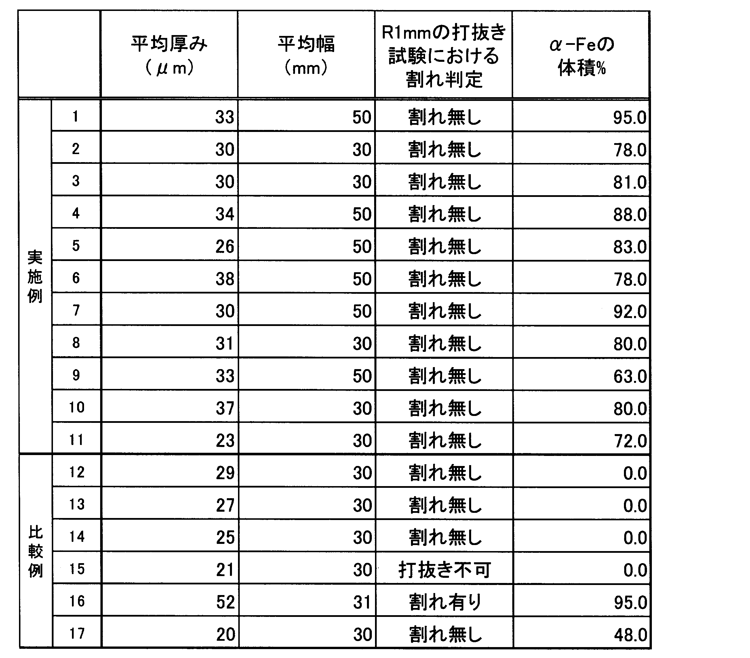
- the iron-based crystal alloy of the present invention is an (Fe,Co)-B-based iron-based crystal alloy having a composite structure of an ⁇ -Fe phase and an Fe-B phase, and has magnetic and mechanical properties that greatly contribute to improving the efficiency of a BLDC motor. If the abundance ratio of the ⁇ -Fe phase is too low, it becomes difficult to ensure Bs ⁇ 1.7T, while if it is too high, coarse ⁇ -Fe of about 10 ⁇ m or more is likely to precipitate, which may become the starting point of cracks during punching press, and furthermore, it is likely to cause an increase in iron loss and a decrease in magnetic permeability.
- the abundance ratio of the ⁇ -Fe phase is 50 vol% or more and less than 95 vol%, preferably 60 vol% or more and less than 90 vol%, and more preferably 60 vol% or more and less than 85 vol%.
- the Fe-B phase is the remaining phase of the ⁇ -Fe phase, and is a phase mainly composed of FeB and Fe2B. As will be described later, the abundance ratio and crystal grain size of the ⁇ -Fe phase can be adjusted to a desired value by controlling the quenching speed of the molten alloy.
- the average crystal grain size of the ⁇ -Fe phase is preferably 2 nm to 20 nm, and can be determined from the half-width of the X-ray diffraction peak by powder X-ray diffraction (XRD) described later.
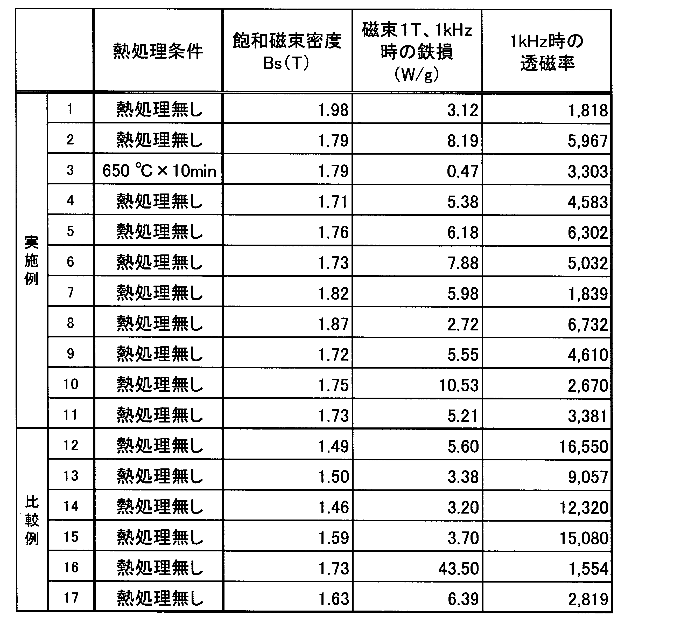
- the iron-based crystalline alloy of the present invention has a saturation magnetic flux density of Bs ⁇ 1.7T, but when considering application to a BLDC motor for driving an EV of 30 kW or more, Bs ⁇ 1.72T is preferable, and Bs ⁇ 1.75T is even more preferable.
- the iron-based crystalline alloy of the present invention has an iron loss (W10/1k) of ⁇ 20 W/kg at a magnetic flux of 1.0 T and a frequency of 1 kHz, which is significantly lower than the iron loss (W10/1k) of silicon steel plate (JIS standard 35A360) of 96.6 W/kg. If the iron loss (W10/1k) exceeds 20 W/kg, the effect of improving motor efficiency decreases. To further improve motor efficiency, it is preferable that the iron loss (W10/1k) is ⁇ 15 W/kg, and it is even more preferable that the iron loss (W10/1k) is ⁇ 10 W/kg.
Landscapes
- Chemical & Material Sciences (AREA)
- Engineering & Computer Science (AREA)
- Mechanical Engineering (AREA)
- Materials Engineering (AREA)
- Metallurgy (AREA)
- Organic Chemistry (AREA)
- Physics & Mathematics (AREA)
- Electromagnetism (AREA)
- Dispersion Chemistry (AREA)
- Power Engineering (AREA)
- Continuous Casting (AREA)
- Soft Magnetic Materials (AREA)
- Thermal Sciences (AREA)
- Crystallography & Structural Chemistry (AREA)
Abstract
Description
鉄基合金の打抜き加工性を改善するには、硬くて割れやすいアモルファス組織ではなく結晶組織にする必要がある。本発明の鉄基結晶合金組成は、Fe-Bの二元合金組成を基本とし、Feの一部を、Feと同じく強磁性元素であるCoで置換したものであり、組成式が(Fe1-yCoy)100-x(B1-zCz)xで表現される。
本発明の鉄基結晶合金は、α-Fe相とFe-B相のコンポジット組織を有する(Fe,Co)-B系鉄基結晶合金であり、BLDCモータの効率向上に大きく寄与する磁気的性質および機械的性質を有する。α-Fe相の存在比率は、低すぎると、Bs≧1.7Tの確保が困難になる一方、高すぎると、10μm以上程度の粗大なα-Feが析出し易いため、打抜きプレス時に割れの起点になるおそれがあり、更には鉄損の増加および透磁率の低下が生じ易い。したがって、α-Fe相の存在比率は、50体積%以上95体積%未満であり、60体積%以上90体積%未満が好ましく、60体積%以上85体積%未満がさらに好ましい。Fe-B相は、α-Fe相の残部の相であり、FeB、Fe2Bを主とする相である。後述するように、α-Fe相は、合金溶湯の急冷速度を制御することにより、存在比率や結晶粒径を所望の値に調整することができる。α-Fe相の平均結晶粒径は、2nm ~ 20 nmであることが好ましい。α‐Fe相の平均結晶粒径は、後述する粉末X線回折(XRD)によるX線回折ビークの半値幅より求めることができる。
本発明の鉄基結晶合金の飽和磁束密度は、Bs≧1.7Tであるが、30kW以上のEV駆動用のBLDCモータの適用を想定した場合、Bs≧1.72Tが好ましく、Bs≧1.75Tがさらに好ましい。
本発明の鉄基結晶合金は、上記の組成を有する(Fe,Co)-B系の合金溶湯を用意する工程と、用意した合金溶湯を急冷凝固する急冷凝固工程を備える鉄基結晶合金の製造方法により製造される。
好ましい実施形態では、(Fe,Co)-B系急冷凝固合金を200℃以上700℃以下の一定温度にて熱処理することにより、急冷凝固合金中の歪除去が可能となり、さらなる低鉄損化を実現できる。熱処理温度が200℃未満では、歪除去の効果が少なく、700℃を超えるとα-Fe相の粗大化が進むため、急冷凝固合金の脆性が増し、打ち抜き加工時に急冷凝固合金が割れ易くなる。上記の熱処理温度は、300℃以上700℃以下が好ましく、400℃以上680℃以下がより好ましい。上記熱処理の熱処理時間は、熱処理装置の均熱帯の形状に依存するが、3分間以上2時間未満の時間範囲内にて、適宜、最適な熱処理時間を選択する。なお、上記熱処理は、真空もしくは不活性ガスの雰囲気で行われることが好ましいが、大気中での熱処理も許容される。
以下、本発明を実施例により更に具体的に説明する。但し、本発明は、以下の実施例に限定されるものではない。


2 溶解炉
3 合金溶湯
4 傾動軸
5 貯湯容器
6 出湯ノズル
7 スリット
8 冷却ロール
9 急冷凝固合金
Claims (3)
- 組成式(Fe1-yCoy)100-x(B1-zCz)xで表現され、x、y、zがそれぞれ10.0≦x≦18.0原子%、0.05≦y≦0.5、0.0≦z≦0.3を満足する組成を有する(Fe,Co)-B系の合金溶湯を用意する工程と、
冷却ロール上で前記合金溶湯を急冷凝固する急冷凝固工程を備え、
前記急冷凝固工程は、前記冷却ロールをロール表面速度15m/sec以上40m/sec以下で回転させながら、前記冷却ロールの表面に前記合金溶湯をシングルスリットノズルからなる出湯ノズルから噴射することにより、α-Fe相の存在比率が50体積%以上95体積%未満であり、残部がFe-B 相からなる鉄基結晶合金を作製する工程を備え、
前記鉄基結晶合金は、厚みが50μm以下の薄帯状に形成され、飽和磁束密度が1.7T以上であり、磁束1.0Tおよび周波数1kHzでの鉄損(W10/1k)が20W/kg以下であり、1kHzでの透磁率が1500以上であり、
前記冷却ロールの表面における算術平均粗さが、0.01μm以上0.6μm以下である鉄基結晶合金の製造方法。 - 前記出湯ノズルは、スリット幅が0.2mm以上0.7mm以下である請求項1に記載の鉄基結晶合金の製造方法。
- 前記出湯ノズルから前記冷却ロールの表面までの距離が、0.2mm以上5.0mm以下である請求項1または2に記載の鉄基結晶合金の製造方法。
Priority Applications (4)
| Application Number | Priority Date | Filing Date | Title |
|---|---|---|---|
| EP24845419.1A EP4685249A1 (en) | 2023-07-21 | 2024-07-11 | Iron-based crystal alloy production method |
| KR1020257039509A KR20260046292A (ko) | 2023-07-21 | 2024-07-11 | 철기결정합금의 제조방법 |
| AU2024299016A AU2024299016A1 (en) | 2023-07-21 | 2024-07-11 | Iron-based crystal alloy production method |
| CN202480038039.4A CN121335994A (zh) | 2023-07-21 | 2024-07-11 | 铁基晶体合金的制造方法 |
Applications Claiming Priority (2)
| Application Number | Priority Date | Filing Date | Title |
|---|---|---|---|
| JP2023-119069 | 2023-07-21 | ||
| JP2023119069A JP7429078B1 (ja) | 2023-07-21 | 2023-07-21 | 鉄基結晶合金の製造方法 |
Publications (1)
| Publication Number | Publication Date |
|---|---|
| WO2025023038A1 true WO2025023038A1 (ja) | 2025-01-30 |
Family
ID=89771002
Family Applications (1)
| Application Number | Title | Priority Date | Filing Date |
|---|---|---|---|
| PCT/JP2024/025071 Pending WO2025023038A1 (ja) | 2023-07-21 | 2024-07-11 | 鉄基結晶合金の製造方法 |
Country Status (6)
| Country | Link |
|---|---|
| EP (1) | EP4685249A1 (ja) |
| JP (1) | JP7429078B1 (ja) |
| KR (1) | KR20260046292A (ja) |
| CN (1) | CN121335994A (ja) |
| AU (1) | AU2024299016A1 (ja) |
| WO (1) | WO2025023038A1 (ja) |
Families Citing this family (3)
| Publication number | Priority date | Publication date | Assignee | Title |
|---|---|---|---|---|
| JP7627981B1 (ja) | 2024-05-27 | 2025-02-07 | ネクストコアテクノロジーズ株式会社 | 鉄基結晶合金の製造方法 |
| JP7656988B1 (ja) * | 2024-09-19 | 2025-04-04 | ネクストコアテクノロジーズ株式会社 | 鉄基軟磁性合金の製造方法 |
| WO2025249247A1 (ja) * | 2024-05-27 | 2025-12-04 | ネクストコアテクノロジーズ株式会社 | 鉄基軟磁性合金の製造方法 |
Citations (10)
| Publication number | Priority date | Publication date | Assignee | Title |
|---|---|---|---|---|
| JPS63220950A (ja) | 1986-06-28 | 1988-09-14 | Nippon Steel Corp | 金属薄帯の製造方法および製造用ノズル |
| JPH05329587A (ja) | 1992-04-10 | 1993-12-14 | Nippon Steel Corp | 板厚の大きな非晶質合金薄帯の製造方法 |
| JPH07113151A (ja) | 1993-10-14 | 1995-05-02 | Nippon Steel Corp | 鉄系アモルファス合金 |
| JPH08124731A (ja) | 1994-10-24 | 1996-05-17 | Nippon Steel Corp | 多層磁性合金薄帯 |
| JP2002053939A (ja) * | 2000-08-04 | 2002-02-19 | Alps Electric Co Ltd | Fe基軟磁性合金磁心の製造方法 |
| CN107103976A (zh) * | 2016-02-22 | 2017-08-29 | 天津大学 | 一种铁钴基韧性纳米晶软磁合金及其制备方法 |
| JP2018153828A (ja) | 2017-03-16 | 2018-10-04 | Bizyme有限会社 | Fe−Si−B系急冷凝固合金薄帯の製造方法 |
| JP2021193199A (ja) | 2020-06-08 | 2021-12-23 | Bizyme有限会社 | Fe−Si−B系急冷凝固合金およびその製造方法 |
| JP2022523627A (ja) * | 2019-01-11 | 2022-04-26 | モナシュ ユニバーシティー | 鉄系合金 |
| WO2022196672A1 (ja) * | 2021-03-17 | 2022-09-22 | Hilltop株式会社 | Fe-Si-B系厚板急冷凝固合金薄帯の製造方法 |
-
2023
- 2023-07-21 JP JP2023119069A patent/JP7429078B1/ja active Active
-
2024
- 2024-07-11 KR KR1020257039509A patent/KR20260046292A/ko active Pending
- 2024-07-11 WO PCT/JP2024/025071 patent/WO2025023038A1/ja active Pending
- 2024-07-11 CN CN202480038039.4A patent/CN121335994A/zh active Pending
- 2024-07-11 AU AU2024299016A patent/AU2024299016A1/en active Pending
- 2024-07-11 EP EP24845419.1A patent/EP4685249A1/en active Pending
Patent Citations (10)
| Publication number | Priority date | Publication date | Assignee | Title |
|---|---|---|---|---|
| JPS63220950A (ja) | 1986-06-28 | 1988-09-14 | Nippon Steel Corp | 金属薄帯の製造方法および製造用ノズル |
| JPH05329587A (ja) | 1992-04-10 | 1993-12-14 | Nippon Steel Corp | 板厚の大きな非晶質合金薄帯の製造方法 |
| JPH07113151A (ja) | 1993-10-14 | 1995-05-02 | Nippon Steel Corp | 鉄系アモルファス合金 |
| JPH08124731A (ja) | 1994-10-24 | 1996-05-17 | Nippon Steel Corp | 多層磁性合金薄帯 |
| JP2002053939A (ja) * | 2000-08-04 | 2002-02-19 | Alps Electric Co Ltd | Fe基軟磁性合金磁心の製造方法 |
| CN107103976A (zh) * | 2016-02-22 | 2017-08-29 | 天津大学 | 一种铁钴基韧性纳米晶软磁合金及其制备方法 |
| JP2018153828A (ja) | 2017-03-16 | 2018-10-04 | Bizyme有限会社 | Fe−Si−B系急冷凝固合金薄帯の製造方法 |
| JP2022523627A (ja) * | 2019-01-11 | 2022-04-26 | モナシュ ユニバーシティー | 鉄系合金 |
| JP2021193199A (ja) | 2020-06-08 | 2021-12-23 | Bizyme有限会社 | Fe−Si−B系急冷凝固合金およびその製造方法 |
| WO2022196672A1 (ja) * | 2021-03-17 | 2022-09-22 | Hilltop株式会社 | Fe-Si-B系厚板急冷凝固合金薄帯の製造方法 |
Non-Patent Citations (2)
| Title |
|---|
| AKIHIRO MAKINOKEN KUBOTAJOSHUNTO: "General Research Center for Metallic Glass", TOHOKU UNIVERSITY |
| See also references of EP4685249A1 |
Also Published As
| Publication number | Publication date |
|---|---|
| EP4685249A1 (en) | 2026-01-28 |
| CN121335994A (zh) | 2026-01-13 |
| JP7429078B1 (ja) | 2024-02-07 |
| AU2024299016A1 (en) | 2025-11-13 |
| JP2025016054A (ja) | 2025-01-31 |
| KR20260046292A (ko) | 2026-04-07 |
Similar Documents
| Publication | Publication Date | Title |
|---|---|---|
| JP7429078B1 (ja) | 鉄基結晶合金の製造方法 | |
| JP7584780B2 (ja) | Fe-Si-B系急冷凝固合金およびその製造方法 | |
| JP4288687B2 (ja) | アモルファス合金組成物 | |
| JP4591633B2 (ja) | ナノコンポジットバルク磁石およびその製造方法 | |
| JP2009174034A (ja) | アモルファス軟磁性合金、アモルファス軟磁性合金薄帯、アモルファス軟磁性合金粉末およびそれを用いた磁心並びに磁性部品 | |
| CN111926268A (zh) | 板材叠层和制造高磁导率软磁合金的方法 | |
| WO2022196672A1 (ja) | Fe-Si-B系厚板急冷凝固合金薄帯の製造方法 | |
| CN103119665B (zh) | 铁磁非晶合金带材及其制造方法 | |
| WO2026070273A1 (ja) | 鉄基軟磁性合金の製造方法 | |
| JP2002030378A (ja) | 結晶化発熱温度制御による鉄基永久磁石合金の製造方法 | |
| JP7627981B1 (ja) | 鉄基結晶合金の製造方法 | |
| JP2018144084A (ja) | 鉄基硼素系合金の製造方法 | |
| WO2023022002A1 (ja) | Fe-Si-B系厚板急冷凝固合金薄帯の製造方法 | |
| JP7765140B1 (ja) | 鉄基軟磁性合金およびその製造方法 | |
| JP7803097B2 (ja) | 軟磁性合金薄帯およびその製造方法、磁心、ならびに部品 | |
| JP7656988B1 (ja) | 鉄基軟磁性合金の製造方法 | |
| WO2025249247A1 (ja) | 鉄基軟磁性合金の製造方法 | |
| KR20210083203A (ko) | 연자성 합금, 연자성 합금 리본, 연자성 합금 리본의 제조방법, 자성 코어, 및 부품 | |
| US20250353063A1 (en) | Rapidly solidified high silicon steel with minor boron addition that improves magnetic properties | |
| JP2003221655A (ja) | ナノコンポジット磁石 | |
| JP4506123B2 (ja) | 希土類急冷磁石合金の製造方法および急冷装置 | |
| JP2023176479A (ja) | 永久磁石及び回転電機 | |
| JP2024165703A (ja) | Fe基ナノ結晶合金用Fe基アモルファス合金リボン、及びFe基ナノ結晶合金用Fe基アモルファス合金リボンの製造方法 | |
| JP2024165702A (ja) | Fe基ナノ結晶合金用Fe基アモルファス合金リボン、及びFe基ナノ結晶合金用Fe基アモルファス合金リボンの製造方法 | |
| CN114823030A (zh) | 软磁性合金、软磁性合金薄带及其制造方法、磁芯、以及部件 |
Legal Events
| Date | Code | Title | Description |
|---|---|---|---|
| 121 | Ep: the epo has been informed by wipo that ep was designated in this application |
Ref document number: 24845419 Country of ref document: EP Kind code of ref document: A1 |
|
| WWE | Wipo information: entry into national phase |
Ref document number: 2024845419 Country of ref document: EP |
|
| WWE | Wipo information: entry into national phase |
Ref document number: AU2024299016 Country of ref document: AU |
|
| ENP | Entry into the national phase |
Ref document number: 2024299016 Country of ref document: AU Date of ref document: 20240711 Kind code of ref document: A |
|
| ENP | Entry into the national phase |
Ref document number: 2024845419 Country of ref document: EP Effective date: 20251022 |
|
| ENP | Entry into the national phase |
Ref document number: 2024845419 Country of ref document: EP Effective date: 20251022 |
|
| ENP | Entry into the national phase |
Ref document number: 2024845419 Country of ref document: EP Effective date: 20251022 |
|
| ENP | Entry into the national phase |
Ref document number: 2024845419 Country of ref document: EP Effective date: 20251022 |
|
| ENP | Entry into the national phase |
Ref document number: 2024845419 Country of ref document: EP Effective date: 20251022 |
|
| ENP | Entry into the national phase |
Ref document number: 2024845419 Country of ref document: EP Effective date: 20251022 |
|
| WWP | Wipo information: published in national office |
Ref document number: 2024845419 Country of ref document: EP |
|
| NENP | Non-entry into the national phase |
Ref country code: DE |