WO2025032905A1 - 建築物の基礎補強構造 - Google Patents
建築物の基礎補強構造 Download PDFInfo
- Publication number
- WO2025032905A1 WO2025032905A1 PCT/JP2024/017692 JP2024017692W WO2025032905A1 WO 2025032905 A1 WO2025032905 A1 WO 2025032905A1 JP 2024017692 W JP2024017692 W JP 2024017692W WO 2025032905 A1 WO2025032905 A1 WO 2025032905A1
- Authority
- WO
- WIPO (PCT)
- Prior art keywords
- improvement body
- ground
- foundation
- building
- concrete
- Prior art date
- Legal status (The legal status is an assumption and is not a legal conclusion. Google has not performed a legal analysis and makes no representation as to the accuracy of the status listed.)
- Pending
Links
Images



Classifications
-
- E—FIXED CONSTRUCTIONS
- E02—HYDRAULIC ENGINEERING; FOUNDATIONS; SOIL SHIFTING
- E02D—FOUNDATIONS; EXCAVATIONS; EMBANKMENTS; UNDERGROUND OR UNDERWATER STRUCTURES
- E02D27/00—Foundations as substructures
- E02D27/01—Flat foundations
- E02D27/08—Reinforcements for flat foundations
-
- E—FIXED CONSTRUCTIONS
- E02—HYDRAULIC ENGINEERING; FOUNDATIONS; SOIL SHIFTING
- E02D—FOUNDATIONS; EXCAVATIONS; EMBANKMENTS; UNDERGROUND OR UNDERWATER STRUCTURES
- E02D27/00—Foundations as substructures
- E02D27/28—Stressing the soil or the foundation structure while forming foundations
-
- E—FIXED CONSTRUCTIONS
- E02—HYDRAULIC ENGINEERING; FOUNDATIONS; SOIL SHIFTING
- E02D—FOUNDATIONS; EXCAVATIONS; EMBANKMENTS; UNDERGROUND OR UNDERWATER STRUCTURES
- E02D3/00—Improving or preserving soil or rock, e.g. preserving permafrost soil
- E02D3/12—Consolidating by placing solidifying or pore-filling substances in the soil
Definitions
- the present invention relates to a foundation reinforcement structure for buildings that is suitable when the supporting layer is relatively shallow or the ground is relatively good.
- This ground improvement body is made by improving the surface layer of the soft ground, and is composed of a horizontal plate-shaped upper improvement body, a peripheral improvement body that hangs down from the underside of the upper improvement body to form an outer frame, and at least one internal improvement body that hangs down from the underside of the upper improvement body, connects the outer frames, and divides the area inside the peripheral improvement body into multiple areas.
- the local soil in the area where the rapple concrete is poured will need to be disposed of. Furthermore, after the rapple concrete is poured, it will be necessary to backfill the excavated area to the side of the rapple concrete with soil, and the strength of the backfill soil will need to be managed.
- Foundation reinforcement which involves installing the ground improvement body under a slab foundation, is suitable for soft ground (for example, ground with a very small N value over a depth of about 20 m).
- the volume of the outer periphery improvement body and the internal improvement body will be larger than necessary in order to form them.
- the foundation concrete is a slab foundation in which reinforced concrete is laid over the entire surface of the ground, which makes construction time and effort even more lengthy.
- the present invention aims to provide a foundation reinforcement structure for buildings that can be constructed in a short period of time, with reduced resource consumption and at low cost when the supporting layer is relatively shallow or the ground is relatively good.
- the gist of the present invention is as follows:
- a foundation reinforcement structure for a building including a ground improvement body obtained by improving the surface ground and foundation concrete poured on the ground improvement body, This method is used when the position of the supporting layer of the surface ground is 5 m or less from the ground surface, or when the surface ground is a natural ground, which is sandy soil or clayey soil, has an N value of 2 or more, and is a ground in which the N value is not smaller at the bottom than at the top in the depth distribution,
- the ground improvement body is composed of an upper improvement body and a lower improvement body,
- the foundation concrete is poured into a recess formed by excavating the ground improvement body,
- the upper improvement body is a horizontal plate-shaped full improvement body,
- the lower improvement body is an independent improvement body located below the column of the building above the foundation concrete and protruding downward from the lower surface of the upper improvement body.
- the foundation concrete is an independent foundation; The foundation reinforcement structure of the building described in [1].
- the foundation reinforcement structure of the present invention includes a ground improvement body and foundation concrete poured on the ground improvement body.
- the upper improvement body of the ground improvement body is a horizontal plate-shaped full-surface improvement body, so that the planar rigidity of the ground surface can be secured, and no underground beams are required.
- the lower improvement body of the ground improvement body is an independent improvement body and is located below the columns of the building, so that the building load transmitted from the columns to the foundation concrete can be dispersed and transmitted to the on-site ground, and the amount of improved soil is significantly reduced.
- the supporting layer of the surface ground is relatively shallow (when the position of the supporting layer is 5m or less from the ground surface) or when the surface ground is relatively good (when the surface ground is a natural mountain, sandy soil or clayey soil, has an N value of 2 or more, and is a ground where the N value depth distribution is not smaller at the bottom than at the top), a short construction period, resource saving, and low cost can be achieved.
- the foundation concrete is poured into a recess formed by excavating the ground improvement body, so the labor required for formwork construction for pouring the foundation concrete can be reduced.
- the labor required for crushed stone construction can be reduced. Therefore, in a foundation reinforcement structure for a building used when the supporting layer of the surface ground is relatively shallow or when the surface ground is relatively good, it is possible to achieve a shorter construction period, resource conservation, and low cost.
- the foundation concrete is an independent foundation, compared to a slab foundation or a strip foundation, the structure only has the foundation under the columns, so in foundation reinforcement structures for buildings used when the supporting layer of the surface ground is relatively shallow or when the surface ground is relatively good, it is possible to achieve even shorter construction periods, resource conservation, and lower costs.
- FIG. 1 is a plan view showing an example of a foundation reinforcement structure for a building according to an embodiment of the present invention.
- 2 is a cross-sectional view taken along the line X1-X1 of FIG. 1.
- 2 is a cross-sectional view taken along the line X2-X2 of FIG. 1.
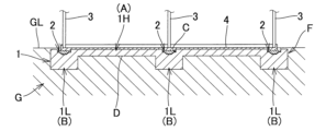
- FIG. 2B is an enlarged view of a main part of FIG. 2A.
- FIG. 1 An example of a foundation reinforcement structure F for a building according to an embodiment of the present invention is shown in the plan view of Figure 1, Figure 2A, a cross-sectional view taken along the line X1-X1 of Figure 1, Figure 2B, a cross-sectional view taken along the line X2-X2 of Figure 1, and Figure 3, an enlarged view of a key portion of Figure 2A.
- the foundation reinforcement structure F of a building includes a ground improvement body 1 that has been made by improving the surface ground G, and foundation concrete 2 that has been poured on top of the ground improvement body 1, and is used when the supporting layer of the surface ground G is relatively shallow (when the position of the supporting layer is 5m or less from the ground surface GL), or when the surface ground G is relatively good (when the surface ground G is natural ground, is sandy soil or clayey soil, has an N value of 2 or more, and is a ground in which the depth distribution of the N value is not smaller at the bottom than at the top).
- the ground improvement body 1 consists of an upper improvement body 1H and a lower improvement body 1L.
- the upper improvement body 1H is a horizontal plate-shaped full-surface improvement body A.
- the lower improvement bodies 1L are rectangular column-shaped independent improvement bodies B (nine in this embodiment) located below the steel columns 3 of the building above the foundation concrete 2 and protruding downward from the lower surface D of the upper improvement body 1H.
- planar shape of one upper improvement body 1H is a square
- planar shapes of the nine lower improvement bodies 1L are also each square.
- the height H1 of the upper improvement body 1H and the height H2 of the lower improvement body 1L shown in FIG. 3 are, for example, 300 mm ⁇ H1 ⁇ 1500 mm and 300 mm ⁇ H2 ⁇ 1500 mm.
- the upper improvement body 1H is a horizontal plate-shaped full improvement body A. This ensures the planar rigidity of the ground surface, eliminating the need for underground beams.
- the lower improvement body 1L is an independent improvement body B, located below the steel column 3. This allows the building load transmitted from the steel column 3 to the foundation concrete 2 to be dispersed and transmitted to the on-site ground, while significantly reducing the amount of improved soil. Therefore, when the supporting layer of the surface ground G is relatively shallow, or when the surface ground G is relatively good, it is possible to achieve a short construction period, resource conservation, and low cost.
- the foundation concrete 2 is poured into a recess C formed by excavating the ground improvement body 1, and is an independent foundation in this embodiment.
- the planar shape of each of the nine foundation concretes 2 in this embodiment is a square, and an example of a three-dimensional shape similar to that of the foundation concrete in Japanese Patent No. 6868301 is shown.
- the depth of the recess C of the ground improvement body 1 into which the foundation concrete 2 is poured is either within the upper improvement body 1H as shown in Figure 3, is flush with the lower surface D of the upper improvement body 1H, or extends into the lower improvement body 1L.
- the labor required for constructing the formwork for pouring the foundation concrete 2 can be reduced.
- the labor required for crushed stone construction can be reduced. Therefore, in the foundation reinforcement structure F of a building used when the supporting layer of the surface ground G is relatively shallow or when the surface ground G is relatively good, it is possible to further shorten the construction period, conserve resources, and reduce costs.
- the foundation concrete 2 is an independent foundation, compared to slab foundations or strip foundations, the structure has a foundation only under the steel columns 3, so in the foundation reinforcement structure F of a building used when the supporting layer of the surface ground G is relatively shallow or when the surface ground G is relatively good, it is possible to achieve even shorter construction periods, resource conservation, and lower costs.
- the planar shape of the foundation concrete 2 does not have to be a square. That is, the planar shape of the foundation concrete 2 may be, for example, a rectangle, or any polygon with four or more sides. It is a preferred embodiment that the planar shape of the lower improvement body 1L, which is the independent improvement body B, matches the planar shape of the foundation concrete 2, which is the independent foundation. That is, if the planar shape of the foundation concrete 2 is an n-gon, which is a polygon, it is a preferred embodiment that the planar shape of the lower improvement body 1L, which is the independent improvement body B, is also an n-gon.
- the size of the planar shape of the lower improvement body 1L is made larger than the size of the planar shape of the foundation concrete, for example, in Figures 1 and 3, it is set to 0 ⁇ E ⁇ 1000 mm.
- the size of the planar shape of the lower improvement body 1L may be set to be smaller than the size of the planar shape of the foundation concrete, for example, -500 mm ⁇ E ⁇ 0.
- the foundation reinforcement structure F of a building is constructed, for example, as follows.
- a cement-based solidification material or other solidification material is spread on the soil in the area where nine rectangular pillar-shaped lower improvement bodies 1L are to be formed.
- the soil and the solidification material are mixed and stirred using a backhoe or other equipment equipped with a mixing fork as an attachment, and then compacted using heavy machinery and rollers to form the lower improvement bodies 1L.
- the soil excavated in the digging process is backfilled and spread evenly in the horizontal plate-like upper improvement body 1H using a backhoe or the like.
- a cement-based solidification material or other solidification material is spread on the backfilled and spread evenly soil.
- the soil and the solidification material are mixed and stirred using a backhoe or the like equipped with a mixing fork as an attachment, and compacted with heavy machinery and rollers to form the upper improvement body 1H.
- the basing concrete 5 shown in Fig. 3 is poured.
- the column base anchor bolts for fixing the steel column 3 are fixed to the basing concrete 5, the foundation reinforcement is arranged, and the foundation concrete 2 is poured.
- the steel column 3 is installed, and the floor concrete 4 is poured.
- the construction period is about 1/3 compared to, for example, the case of using rapple concrete to reinforce the foundation as in Patent Document 1.
- the amount of improved soil in the primary improvement process is about 1/4 compared to, for example, the case of installing a ground improvement body under a slab foundation as in Patent Document 2, where the ground improvement body is formed by a horizontal plate-shaped upper improvement body, a peripheral improvement body that hangs down from the underside of the upper improvement body to form an outer frame, and an internal improvement body that hangs down from the underside of the upper improvement body, connects the outer frames, and divides the area inside the peripheral improvement body into multiple areas.
Landscapes
- Engineering & Computer Science (AREA)
- Life Sciences & Earth Sciences (AREA)
- Structural Engineering (AREA)
- General Engineering & Computer Science (AREA)
- Paleontology (AREA)
- Civil Engineering (AREA)
- Mining & Mineral Resources (AREA)
- General Life Sciences & Earth Sciences (AREA)
- Agronomy & Crop Science (AREA)
- Environmental & Geological Engineering (AREA)
- Soil Sciences (AREA)
- Consolidation Of Soil By Introduction Of Solidifying Substances Into Soil (AREA)
- Foundations (AREA)
Abstract
【課題】支持層が比較的浅い場合又は地盤が比較的良い場合に、短工期、省資源、ローコストを実現できる建築物の基礎補強構造を提供する。 【解決手段】表層地盤を改良した地盤改良体1及びその上に打設した基礎コンクリート2を含む建築物の基礎補強構造Fである。前記表層地盤の支持層の位置が地表面から5m以下である場合、又は、前記表層地盤が、地山で、砂質土若しくは粘性土で、N値は2以上であり、N値の深度分布において上方よりも下方が小さくならない地盤である場合に用いる。地盤改良体1は、上部改良体1H及び下部改良体1Lからなる。基礎コンクリート2は、地盤改良体1を掘削して形成した凹部内に打設される。上部改良体1Hは、水平板状の全面改良体Aである。下部改良体1Lは、基礎コンクリート2の上方の建築物の柱3の下方に位置し、上部改良体1Hの下面から下方へ突出する独立改良体Bである。
Description
本発明は、支持層が比較的浅い場合、又は地盤が比較的良い場合に好適な建築物の基礎補強構造に関する。
支持層が比較的浅い場合の建築物の基礎補強として、建築物の基礎下の支持層までの地盤をコンクリートに置換するラップルコンクリートが一般的に採用される(例えば、特許文献1参照)。
他方、軟弱地盤上に建築物を建築する場合の基礎補強として、べた基礎の下に地盤改良体を設置するものがある(例えば、特許文献2参照)。この地盤改良体は、軟弱地盤の表層部を改良したものであり、水平板状の上部改良体と、前記上部改良体の下面から垂下して外枠を形成する外周部改良体と、前記上部改良体の下面から垂下して、前記外枠間を連結して前記外周部改良体の内側の領域を複数の領域に仕切る少なくとも1個の内部改良体とにより形成される。
ラップルコンクリートにより基礎補強を行う場合、ラップルコンクリートを打設するための型枠を設置する必要があり、前記型枠を設置するために、掘削孔を大きく余堀りする必要がある。
また、ラップルコンクリート打設部分の現地土は残土処分が必要である。さらに、ラップルコンクリートの打設後に、ラップルコンクリートの側方の余掘部に土を埋め戻す必要があるとともに、埋戻し土の強度管理が必要になる。
また、前記型枠の設置、及び脱型の工期と手間が掛かる。さらに、ラップルコンクリートの上は、通常の基礎形式であるため、基礎の型枠設置、配筋及び脱型、並びに基礎の側方に土を埋め戻す必要があるとともに、埋戻し土の強度管理が必要になる。
べた基礎の下に前記地盤改良体を設置する基礎補強は、軟弱地盤(例えば、約20m程度の深さにわたりN値が非常に小さい地盤)には好適なものである。
しかしながら、対象地盤が軟弱地盤ではなく、支持層が比較的浅い場合、又は地盤が比較的良い場合には、前記外周部改良体及び前記内部改良体を形成するために、それらの体積が必要以上に大きくなってしまう。
したがって、改良土量の増大によりセメント系固化材等の固化材の使用量が増大するとともに、工期と手間が掛かる。その上、基礎コンクリートが、地面一面に鉄筋コンクリートを施工するべた基礎であるので、一層工期と手間が掛かる。
本発明は、支持層が比較的浅い場合、又は地盤が比較的良い場合に、短工期、省資源、及びローコストを実現できる建築物の基礎補強構造を提供することを目的とする。
本発明の要旨は以下のとおりである。
〔1〕
表層地盤を改良した地盤改良体及び前記地盤改良体上に打設した基礎コンクリートを含む建築物の基礎補強構造であって、
前記表層地盤の支持層の位置が地表面から5m以下である場合、又は、前記表層地盤が、地山で、砂質土若しくは粘性土で、N値は2以上であり、N値の深度分布において上方よりも下方が小さくならない地盤である場合に用いられ、
前記地盤改良体は、上部改良体及び下部改良体からなり、
前記基礎コンクリートは、前記地盤改良体を掘削して形成した凹部内に打設されたものであり、
前記上部改良体は、水平板状の全面改良体であり、
前記下部改良体は、前記基礎コンクリートの上方の建築物の柱の下方に位置し、前記上部改良体の下面から下方へ突出する独立改良体である、
建築物の基礎補強構造。
表層地盤を改良した地盤改良体及び前記地盤改良体上に打設した基礎コンクリートを含む建築物の基礎補強構造であって、
前記表層地盤の支持層の位置が地表面から5m以下である場合、又は、前記表層地盤が、地山で、砂質土若しくは粘性土で、N値は2以上であり、N値の深度分布において上方よりも下方が小さくならない地盤である場合に用いられ、
前記地盤改良体は、上部改良体及び下部改良体からなり、
前記基礎コンクリートは、前記地盤改良体を掘削して形成した凹部内に打設されたものであり、
前記上部改良体は、水平板状の全面改良体であり、
前記下部改良体は、前記基礎コンクリートの上方の建築物の柱の下方に位置し、前記上部改良体の下面から下方へ突出する独立改良体である、
建築物の基礎補強構造。
〔2〕
前記基礎コンクリートは独立基礎である、
〔1〕に記載の建築物の基礎補強構造。
前記基礎コンクリートは独立基礎である、
〔1〕に記載の建築物の基礎補強構造。
本発明の建築物の基礎補強構造は、地盤改良体及び前記地盤改良体上に打設した基礎コンクリートを含む。前記地盤改良体の上部改良体は、水平板状の全面改良体であることから、地盤面の平面剛性が確保できるので、地中梁が不要となる。前記地盤改良体の下部改良体は、独立改良体であり、建築物の柱の下方に位置することから、前記柱から前記基礎コンクリートに伝達された建物荷重を分散して現地盤に伝えることができるとともに、改良土量が大幅に少なくなる。したがって、表層地盤の支持層が比較的浅い場合(前記支持層の位置が地表面から5m以下である場合)、又は表層地盤が比較的良い場合(前記表層地盤が、地山で、砂質土若しくは粘性土で、N値は2以上であり、N値の深度分布において上方よりも下方が小さくならない地盤である場合)において、短工期、省資源、及びローコストを実現できる。
前記基礎コンクリートは、前記地盤改良体を掘削して形成した凹部内に打設されたものであるので、前記基礎コンクリートを打設するための型枠施工を省力化できる。また、通常は捨てコンクリート下に設ける必要がある砕石層を設ける必要がなくなるので、砕石施工を省力化できる。したがって、表層地盤の支持層が比較的浅い場合、又は表層地盤が比較的良い場合に用いる建築物の基礎補強構造において、さらに、短工期、省資源、及びローコストを実現できる。
前記基礎コンクリートが独立基礎である場合は、べた基礎又は布基礎である場合と比較して、柱の下にのみ基礎を設ける構造であるので、表層地盤の支持層が比較的浅い場合、又は表層地盤が比較的良い場合に用いる建築物の基礎補強構造において、より一層、短工期、省資源、及びローコストを実現できる。
以下、本発明の実施形態を図面に基づいて説明する。
[建築物の基礎補強構造]
本発明の実施形態に係る建築物の基礎補強構造Fの例を、図1の平面図、図1の矢視X1-X1断面図である図2A、及び図1の矢視X2-X2断面図である図2B、並びに、図2Aの要部拡大図である図3に示す。
本発明の実施形態に係る建築物の基礎補強構造Fの例を、図1の平面図、図1の矢視X1-X1断面図である図2A、及び図1の矢視X2-X2断面図である図2B、並びに、図2Aの要部拡大図である図3に示す。
建築物の基礎補強構造Fは、表層地盤Gを改良した地盤改良体1及び地盤改良体1上に打設した基礎コンクリート2を含み、表層地盤Gの支持層が比較的浅い場合(前記支持層の位置が地表面GLから5m以下である場合)、又は表層地盤Gが比較的良い場合(表層地盤Gが、地山で、砂質土若しくは粘性土で、N値は2以上であり、N値の深度分布において上方よりも下方が小さくならない地盤である場合)に用いる。
[地盤改良体]
地盤改良体1は、上部改良体1H及び下部改良体1Lからなる。上部改良体1Hは、水平板状の全面改良体Aである。下部改良体1Lは、基礎コンクリート2の上方の建築物の鉄骨柱3の下方に位置し、上部改良体1Hの下面Dから下方へ突出する、本実施形態では9個である四角柱状の独立改良体Bである。
地盤改良体1は、上部改良体1H及び下部改良体1Lからなる。上部改良体1Hは、水平板状の全面改良体Aである。下部改良体1Lは、基礎コンクリート2の上方の建築物の鉄骨柱3の下方に位置し、上部改良体1Hの下面Dから下方へ突出する、本実施形態では9個である四角柱状の独立改良体Bである。
本実施形態では、図1に示すように、1個の上部改良体1Hの平面形状は正方形であり、9個の下部改良体1Lの平面形状も夫々正方形である。
図3に示す上部改良体1Hの高さH1、及び下部改良体1Lの高さH2は、例えば、300mm≦H1≦1500mm、300mm≦H2≦1500mmである。
上部改良体1Hは水平板状の全面改良体Aである。そのため、地盤面の平面剛性が確保できるので、地中梁が不要となる。下部改良体1Lは独立改良体Bであり、鉄骨柱3の下方に位置する。そのため、鉄骨柱3から基礎コンクリート2に伝達された建物荷重を分散して現地盤に伝えることができるとともに、改良土量が大幅に少なくなる。したがって、表層地盤Gの支持層が比較的浅い場合、又は表層地盤Gが比較的良い場合において、短工期、省資源、及びローコストを実現できる。
[基礎コンクリート]
図2A及び図3に示すように、基礎コンクリート2は、地盤改良体1を掘削して形成した凹部C内に打設されたものであり、本実施形態では、独立基礎である。図1に示すように、本実施形態では9個である基礎コンクリート2の平面形状は、夫々正方形であり、例えば特許第6868301号公報における基礎コンクリートと同様の立体形状である場合の例を示している。
図2A及び図3に示すように、基礎コンクリート2は、地盤改良体1を掘削して形成した凹部C内に打設されたものであり、本実施形態では、独立基礎である。図1に示すように、本実施形態では9個である基礎コンクリート2の平面形状は、夫々正方形であり、例えば特許第6868301号公報における基礎コンクリートと同様の立体形状である場合の例を示している。
基礎コンクリート2を打設する地盤改良体1の凹部Cの深さは、図3のように上部改良体1H内である場合、上部改良体1Hの下面Dと面一である場合、及び下部改良体1L内まで及ぶ場合の何れかである。
地盤改良体1を掘削して形成した凹部C内に基礎コンクリート2を打設することにより、基礎コンクリート2を打設するための型枠施工を省力化できる。また、通常は捨てコンクリート下に設ける必要がある砕石層を設ける必要がなくなるので(図3の捨てコンクリート5参照)、砕石施工を省力化できる。したがって、表層地盤Gの支持層が比較的浅い場合、又は表層地盤Gが比較的良い場合に用いる建築物の基礎補強構造Fにおいて、さらに、短工期、省資源、及びローコストを実現できる。
また、基礎コンクリート2が独立基礎であることから、べた基礎又は布基礎である場合と比較して、鉄骨柱3の下にのみ基礎を設ける構造であるので、表層地盤Gの支持層が比較的浅い場合、又は表層地盤Gが比較的良い場合に用いる建築物の基礎補強構造Fにおいて、より一層、短工期、省資源、及びローコストを実現できる。
基礎コンクリート2の平面形状は、正方形でなくてもよい。すなわち、基礎コンクリート2の平面形状は、例えば、長方形でもよく、四角形以上の多角形であればよい。独立改良体Bである下部改良体1Lの平面形状は、独立基礎である基礎コンクリート2の平面形状に合わせるのが好ましい実施態様である。すなわち、基礎コンクリート2の平面形状が前記多角形であるn角形である場合、独立改良体Bである下部改良体1Lの平面形状もn角形にするのが好ましい実施態様である。
また、下部改良体1Lの平面形状の大きさは、基礎コンクリートの平面形状の大きさよりも大きくする場合、例えば、図1及び図3において、0<E≦1000mmとする。あるいは、下部改良体1Lの平面形状の大きさを、基礎コンクリートの平面形状の大きさ以下にする場合もあり、例えば、-500mm<E≦0とする。
[建築物の基礎補強構造等の施工工程]
建築物の基礎補強構造F等は、例えば、以下のように施工する。
建築物の基礎補強構造F等は、例えば、以下のように施工する。
<地盤改良工程>
(掘下げ工程)
図2A及び図2B、並びに図3に示す地表面GLから下側の表層地盤Gを、例えばバックホウによる鋤取り等により、上部改良体1Hの所要形状に掘り下げる。
(掘下げ工程)
図2A及び図2B、並びに図3に示す地表面GLから下側の表層地盤Gを、例えばバックホウによる鋤取り等により、上部改良体1Hの所要形状に掘り下げる。
(一次改良工程)
9箇所の四角柱状の下部改良体1Lを形成する範囲の土の上に、セメント系固化材等の固化材を散布する。アタッチメントとしてミキシングフォークを装着したバックホウ等により、前記土及び前記固化材を混合撹拌し、重機及びローラー等により締め固めて下部改良体1Lを形成する。
9箇所の四角柱状の下部改良体1Lを形成する範囲の土の上に、セメント系固化材等の固化材を散布する。アタッチメントとしてミキシングフォークを装着したバックホウ等により、前記土及び前記固化材を混合撹拌し、重機及びローラー等により締め固めて下部改良体1Lを形成する。
(二次改良工程)
前記掘下げ工程により掘り下げた土を、水平板状の上部改良体1Hの部分に、バックホウ等により埋め戻して敷き均す。埋め戻して敷き均した前記土の上に、セメント系固化材等の固化材を散布する。アタッチメントとしてミキシングフォークを装着したバックホウ等により、前記土及び前記固化材を混合撹拌し、重機及びローラー等により締め固めて上部改良体1Hを形成する。
前記掘下げ工程により掘り下げた土を、水平板状の上部改良体1Hの部分に、バックホウ等により埋め戻して敷き均す。埋め戻して敷き均した前記土の上に、セメント系固化材等の固化材を散布する。アタッチメントとしてミキシングフォークを装着したバックホウ等により、前記土及び前記固化材を混合撹拌し、重機及びローラー等により締め固めて上部改良体1Hを形成する。
<基礎掘削工程>
前記地盤改良工程で構築した地盤改良体1に対し、鉄骨柱3の地上側部分の下方に位置する地盤改良体1の上部を、バックホウ等により所定深さまで基礎コンクリート2の立体形状に掘削し、凹部Cを形成する。
前記地盤改良工程で構築した地盤改良体1に対し、鉄骨柱3の地上側部分の下方に位置する地盤改良体1の上部を、バックホウ等により所定深さまで基礎コンクリート2の立体形状に掘削し、凹部Cを形成する。
<基礎打設工程>
図3に示す捨てコンクリート5を打設する。鉄骨柱3固定用の柱脚アンカーボルトを捨てコンクリート5に固定し、基礎配筋を行って基礎コンクリート2を打設する。鉄骨柱3を設置し、土間コンクリート4を打設する。
図3に示す捨てコンクリート5を打設する。鉄骨柱3固定用の柱脚アンカーボルトを捨てコンクリート5に固定し、基礎配筋を行って基礎コンクリート2を打設する。鉄骨柱3を設置し、土間コンクリート4を打設する。
以上の工程により建築物の基礎補強構造F等の施工が完了する。
本発明の実施形態に係る建築物の基礎補強構造によれば、例えば、特許文献1のようなラップルコンクリートにより基礎補強を行う場合と比較して工期が約1/3程度になる。また、本発明の実施形態に係る建築物の基礎補強構造によれば、例えば、特許文献2のようなべた基礎の下に地盤改良体を設置し、前記地盤改良体が、水平板状の上部改良体と、前記上部改良体の下面から垂下して外枠を形成する外周部改良体と、前記上部改良体の下面から垂下して、前記外枠間を連結して前記外周部改良体の内側の領域を複数の領域に仕切る内部改良体とにより形成されるものと比較して、一次改良工程における改良土量が約1/4程度になる。
以上の実施形態の記載はすべて例示であり、これに制限されるものではない。本発明の範囲から逸脱することなく種々の改良及び変更を施すことができる。
1 地盤改良体
1H 上部改良体
1L 下部改良体
2 基礎コンクリート
3 鉄骨柱
4 土間コンクリート
5 捨てコンクリート
A 全面改良体
B 独立改良体
C 凹部
D 下面
E 下部改良体の平面形状の大きさと基礎コンクリートの平面形状の大きさとの差
F 建築物の基礎補強構造
G 表層地盤
GL 地表面
H1 上部改良体の高さ
H2 下部改良体の高さ
1H 上部改良体
1L 下部改良体
2 基礎コンクリート
3 鉄骨柱
4 土間コンクリート
5 捨てコンクリート
A 全面改良体
B 独立改良体
C 凹部
D 下面
E 下部改良体の平面形状の大きさと基礎コンクリートの平面形状の大きさとの差
F 建築物の基礎補強構造
G 表層地盤
GL 地表面
H1 上部改良体の高さ
H2 下部改良体の高さ
Claims (2)
- 表層地盤を改良した地盤改良体及び前記地盤改良体上に打設した基礎コンクリートを含む建築物の基礎補強構造であって、
前記表層地盤の支持層の位置が地表面から5m以下である場合、又は、前記表層地盤が、地山で、砂質土若しくは粘性土で、N値は2以上であり、N値の深度分布において上方よりも下方が小さくならない地盤である場合に用いられ、
前記地盤改良体は、上部改良体及び下部改良体からなり、
前記基礎コンクリートは、前記地盤改良体を掘削して形成した凹部内に打設されたものであり、
前記上部改良体は、水平板状の全面改良体であり、
前記下部改良体は、前記基礎コンクリートの上方の建築物の柱の下方に位置し、前記上部改良体の下面から下方へ突出する独立改良体である、
建築物の基礎補強構造。 - 前記基礎コンクリートは独立基礎である、
請求項1に記載の建築物の基礎補強構造。
Applications Claiming Priority (2)
| Application Number | Priority Date | Filing Date | Title |
|---|---|---|---|
| JP2023-128554 | 2023-08-07 | ||
| JP2023128554A JP7724000B2 (ja) | 2023-08-07 | 2023-08-07 | 建築物の基礎補強構造 |
Publications (1)
| Publication Number | Publication Date |
|---|---|
| WO2025032905A1 true WO2025032905A1 (ja) | 2025-02-13 |
Family
ID=94533939
Family Applications (1)
| Application Number | Title | Priority Date | Filing Date |
|---|---|---|---|
| PCT/JP2024/017692 Pending WO2025032905A1 (ja) | 2023-08-07 | 2024-05-13 | 建築物の基礎補強構造 |
Country Status (2)
| Country | Link |
|---|---|
| JP (1) | JP7724000B2 (ja) |
| WO (1) | WO2025032905A1 (ja) |
Citations (4)
| Publication number | Priority date | Publication date | Assignee | Title |
|---|---|---|---|---|
| JP2005146556A (ja) * | 2003-11-12 | 2005-06-09 | Kinji Takeuchi | 地盤改良体及びべた基礎からなる建築物の基礎の構造並びに地盤改良べた基礎工法 |
| WO2019008866A1 (ja) * | 2017-07-04 | 2019-01-10 | 株式会社タケウチ建設 | 建築物の基礎構造、及びその施工方法 |
| WO2021111690A1 (ja) * | 2019-12-02 | 2021-06-10 | 株式会社タケウチ建設 | 建築物の基礎構造、及びその施工方法 |
| WO2023132126A1 (ja) * | 2022-01-07 | 2023-07-13 | 株式会社タケウチ建設 | 地盤改良体 |
-
2023
- 2023-08-07 JP JP2023128554A patent/JP7724000B2/ja active Active
-
2024
- 2024-05-13 WO PCT/JP2024/017692 patent/WO2025032905A1/ja active Pending
Patent Citations (4)
| Publication number | Priority date | Publication date | Assignee | Title |
|---|---|---|---|---|
| JP2005146556A (ja) * | 2003-11-12 | 2005-06-09 | Kinji Takeuchi | 地盤改良体及びべた基礎からなる建築物の基礎の構造並びに地盤改良べた基礎工法 |
| WO2019008866A1 (ja) * | 2017-07-04 | 2019-01-10 | 株式会社タケウチ建設 | 建築物の基礎構造、及びその施工方法 |
| WO2021111690A1 (ja) * | 2019-12-02 | 2021-06-10 | 株式会社タケウチ建設 | 建築物の基礎構造、及びその施工方法 |
| WO2023132126A1 (ja) * | 2022-01-07 | 2023-07-13 | 株式会社タケウチ建設 | 地盤改良体 |
Also Published As
| Publication number | Publication date |
|---|---|
| JP7724000B2 (ja) | 2025-08-15 |
| JP2025024444A (ja) | 2025-02-20 |
Similar Documents
| Publication | Publication Date | Title |
|---|---|---|
| CN102444142B (zh) | 一种群桩改柱扩建地下室及其施工工法 | |
| CN109024662A (zh) | 锚杆静压桩托换无地下室建筑地下空间增层的方法 | |
| KR100313720B1 (ko) | 가설 흙막이 벽용 철골 버팀대를 영구 구조물의 일부로 사용하는 | |
| KR100376590B1 (ko) | 영구 구조물의 일부를 토공사용 버팀대로 활용하는 공사방법을 이용한 구획식 공사방법 | |
| RU2392387C2 (ru) | Устройство и способ усиления основания мачты | |
| JP5228862B2 (ja) | 地下構造、地下構造の構築方法 | |
| CN106988337B (zh) | 一种用于减小条形浅基础房屋不均匀沉降的加固方法 | |
| KR102223856B1 (ko) | 폐기물 매립장 기초 구조 및 이의 시공 방법 | |
| JP2020159006A (ja) | 擁壁及びその施工方法 | |
| JP7724000B2 (ja) | 建築物の基礎補強構造 | |
| JP3390081B2 (ja) | 地下駐車場の構築方法 | |
| JP3760304B2 (ja) | 建物の基礎施工方法 | |
| JPS62260919A (ja) | 基礎地盤の耐震補強方法 | |
| JP3641227B2 (ja) | 地下構造躯体の施工法 | |
| CN219773022U (zh) | 一种生态pc基础胎模结构 | |
| CN1333139C (zh) | 一种柱支式地下连续墙 | |
| CN111501829B (zh) | 回填式地下室施工方法 | |
| JP2019173453A (ja) | 建物の構築方法 | |
| JPH11350746A (ja) | 建造物の地下構造 | |
| JPH07138972A (ja) | 地下躯体の構築法 | |
| JP7735014B1 (ja) | 建築方法及び建築物 | |
| JP3059058U (ja) | 安定材付きベタ基礎構造 | |
| JP7398609B2 (ja) | コンクリート躯体の構築方法及び地中構造物 | |
| JP4031284B2 (ja) | 地下構造物の構築工法 | |
| CN220503948U (zh) | 一种用于地下结构降板施工的永临结合施工便道结构 |
Legal Events
| Date | Code | Title | Description |
|---|---|---|---|
| 121 | Ep: the epo has been informed by wipo that ep was designated in this application |
Ref document number: 24851339 Country of ref document: EP Kind code of ref document: A1 |
|
| NENP | Non-entry into the national phase |
Ref country code: DE |