WO2025041278A1 - Reinforced concrete skeleton for house, and method for designing reinforced concrete skeleton for house - Google Patents
Reinforced concrete skeleton for house, and method for designing reinforced concrete skeleton for house Download PDFInfo
- Publication number
- WO2025041278A1 WO2025041278A1 PCT/JP2023/030200 JP2023030200W WO2025041278A1 WO 2025041278 A1 WO2025041278 A1 WO 2025041278A1 JP 2023030200 W JP2023030200 W JP 2023030200W WO 2025041278 A1 WO2025041278 A1 WO 2025041278A1
- Authority
- WO
- WIPO (PCT)
- Prior art keywords
- depth
- line segment
- frontage
- beams
- length
- Prior art date
- Legal status (The legal status is an assumption and is not a legal conclusion. Google has not performed a legal analysis and makes no representation as to the accuracy of the status listed.)
- Pending
Links
Images







Classifications
-
- E—FIXED CONSTRUCTIONS
- E04—BUILDING
- E04B—GENERAL BUILDING CONSTRUCTIONS; WALLS, e.g. PARTITIONS; ROOFS; FLOORS; CEILINGS; INSULATION OR OTHER PROTECTION OF BUILDINGS
- E04B1/00—Constructions in general; Structures which are not restricted either to walls, e.g. partitions, or floors or ceilings or roofs
- E04B1/18—Structures comprising elongated load-supporting parts, e.g. columns, girders, skeletons
- E04B1/20—Structures comprising elongated load-supporting parts, e.g. columns, girders, skeletons the supporting parts consisting of concrete, e.g. reinforced concrete, or other stonelike material
Definitions
- This invention relates to a reinforced concrete structure for a house and its design method.
- the term "house” includes both detached houses and apartment buildings.
- the structure of columns and beams (for example, the thickness of the columns and beams, and the position and number of reinforcing bars arranged inside them) is almost always different for each column or beam, and it is more common to adopt a complex structure in which the structure of columns and beams is different for each column or beam, in order to achieve both the fulfillment of the safety performance required for the building after construction and the reduction of the cost of construction materials as low as possible.
- structural designs have become too complicated, and in most cases, they are performed using dedicated software installed on a computer, and the dedicated software is created using the approach described above.
- structural design is extremely complicated. This causes other problems.
- the work done by structural designers is extremely complicated, and therefore the time required for structural design itself is long and the cost required for structural design is often relatively high.
- the structural design of even a detached house with a reinforced concrete frame takes about two months and costs 500,000 to 1,000,000 yen.
- the materials needed to build the building and the number of construction steps (which relate to the labor costs required during construction) are not finalized, and so the cost required to build the building cannot be estimated.
- structural design could be simplified, for example by reducing costs, it could potentially resolve some of the issues preventing the widespread use of concrete-framed homes.
- structural design has the objective of "generally designing the foundations and framework of a building economically while satisfying safety performance so that it can withstand various loads," and where it is believed that the correct approach to achieve this objective is to "achieve both the satisfaction of the safety performance required for the building after construction and the reduction of construction material costs as much as possible by adopting a complex structure in which the structures of columns and beams are different for each column or beam," the idea of simplifying structural design does not even exist. Therefore, at least at present, no realistic means have been proposed to make structural design cheaper.
- the present invention aims to propose a technology that simplifies structural design, making it possible to complete the design in a short time and at a low cost, and in some cases, even reducing the costs required to build a house.
- the technology is concerned exclusively with reinforced concrete frameworks for houses, or design methods.
- the invention proposed by the applicant to solve the above problems will first be outlined.
- conventional structural design is complicated.
- the reason why structural design becomes complicated is, for example, to ensure the strength of the building or house provided by the columns and beams by giving only the minimum necessary strength to the components of the rigid frame structure, such as columns and beams, while minimizing the cost of construction materials.
- the simplest shape for a rigid frame structure in which the load of a building or house is supported by columns and beams is a rectangular parallelepiped frame, which includes four beams each extending in the horizontal and mutually perpendicular x- and y-directions, and four columns extending in the vertical z-direction.
- a frame with a specific shape as a reference frame
- adjacent reference frames columns and beams that overlap each other are combined into one. This makes it possible to construct a rectangular parallelepiped frame with a certain degree of freedom.
- a reinforced concrete structure including a new frame obtained by arranging X pieces of reference frames including the above-mentioned standardized columns and beams in the x direction, Y pieces in the y direction, and Z pieces in the z direction can always support the load of a house including it, then a reinforced concrete structure including a new frame obtained by arranging X pieces of frames (quasi-reference frames) in the x direction, Y pieces in the y direction, and Z pieces in the z direction, which conform to a reference frame that is smaller in at least one of the x direction, y direction, and z direction than a reference frame equipped with columns and beams similar to the standardized columns
- the reinforced concrete skeleton with standardized columns and beams can improve the efficiency of construction work by reducing the difficulty of work when actually constructing the reinforced concrete skeleton, which may result in a reduction in labor costs.
- construction materials e.g., reinforcing bars
- the cost of constructing a reinforced concrete skeleton designed with a simple structural design is often lower than before, even taking into account the increase in cost due to the excessive performance of the columns and beams.
- the present invention was made based on this idea.
- the present invention is realized as a reinforced concrete structure for a house (hereinafter sometimes simply referred to as a "reinforced concrete structure") as described below.
- the reinforced concrete structure of the present invention is constructed based on a rectangular area, which is a rectangular area in a plan view defined by a frontage line, which is a virtual line segment of a predetermined length extending in the frontage direction, and a depth line, which is a virtual line segment of a predetermined length extending from one end of the frontage line in a direction perpendicular to the frontage line.
- the reinforced concrete structure of the present invention has a plurality of columns which are vertical, elongated members having a length equal to or less than a predetermined third length, which are erected in pairs at least both ends of two sides parallel to the depth line segment of the above-mentioned rectangular range, and at depth division positions which are positions on the two sides that evenly divide the two sides parallel to the depth line segment into lengths equal to or less than the first length when the two sides are longer than a predetermined first length, and which are also erected at both ends of an auxiliary line segment which is a virtual line segment of the same length as the depth line segment and extends parallel to the depth line segment from a frontage division position which is a position on the frontage line segment that evenly divides the frontage line segment into lengths equal to or less than the second length when the frontage line segment is longer than a predetermined second length, and at positions corresponding to the depth division positions on the auxiliary line segment.
- the reinforced concrete structure of the present invention has a plurality of frontage beams, which are long members that horizontally connect the upper and lower ends of all two of the columns that are parallel to and adjacent to the frontage line, in a direction parallel to the frontage line, and a plurality of foundation frontage beams that are in contact with the ground among the frontage beams.
- the system includes a plurality of depth beams which are long members that horizontally connect the upper and lower ends of all two of the columns that are parallel to and adjacent to the depth line in a direction parallel to the depth line, and a plurality of foundation depth beams which are in contact with the ground among the depth beams.
- the reinforced concrete structure of the present invention has a plurality of walls that seal the gap between adjacent columns located on two sides parallel to the frontage line of the rectangular area in a plate-like manner parallel to the frontage line, or that seal the gap between adjacent columns located on two sides parallel to the depth line of the rectangular area or on the auxiliary line in a plate-like manner parallel to the depth line.
- the reinforced concrete structure of the present invention has a plurality of slabs that horizontally fill a rectangular space surrounded by two of the front beams and two of the depth beams, or two of the foundation front beams and two of the foundation depth beams, at height positions above and below the columns.
- all of the multiple columns have the same thickness and longitudinal reinforcing bar configuration
- all of the multiple frontage beams have the same thickness and longitudinal reinforcing bar configuration
- all of the multiple foundation frontage beams have the same thickness and longitudinal reinforcing bar configuration
- all of the multiple depth beams have the same thickness and longitudinal reinforcing bar configuration
- all of the multiple foundation depth beams have the same thickness and longitudinal reinforcing bar configuration
- all of the multiple walls have the same configuration per specified unit area
- all of the multiple slabs have the same configuration per specified unit area.
- the reinforced concrete skeleton of the present invention is constructed based on a rectangular area.
- the rectangular area is a rectangular area when viewed from above.
- the planar shape of the rectangular area is defined by two lines that are perpendicular to each other when viewed from above.
- One of the two lines is a frontage line, and the other is a depth line.
- the reinforced concrete structure has a frame constructed by arranging at least one rectangular parallelepiped frame corresponding to the reference frame described above in the length, width, and height directions.
- the frame is constructed of columns, front beams, and depth beams.
- the front beams that come into contact with the ground are foundation front beams
- the depth beams that come into contact with the ground are foundation depth beams.
- the foundation front beams and foundation depth beams also serve as the foundation.
- the pillars are erected at least at both ends of the two sides parallel to the depth line segment of the rectangular range. In other words, the pillars are always erected at the four corners of the rectangular range.
- the depth line segment is longer than a first length, which is a predetermined length
- the pillars are also erected at a depth division position, which is a position on the two sides that divides the two sides parallel to the depth line segment into lengths equal to or less than the first length.
- the pillars are also erected at both ends of the auxiliary line segment, which is a virtual line segment of the same length as the depth line segment that extends parallel to the depth line segment from the frontage division position, which is a position on the frontage line segment that divides the frontage line segment into lengths equal to or less than the second length, and at a position corresponding to the depth division position when the depth division position exists on the depth line segment.
- the pillars are vertical, and their length is equal to or less than a third length, which is a predetermined length.
- the frontage beam and foundation frontage beam are as follows.
- the frontage beam horizontally connects the upper and lower ends of all two columns that are parallel to the frontage line and adjacent to each other in a direction parallel to the frontage line.
- the frontage beam is a long material.
- the frontage beam that comes into contact with the ground is the foundation frontage beam.
- the distance between two adjacent columns located on a straight line parallel to the frontage line across which the frontage beam is stretched is less than the second length, so the length of the frontage beam (and foundation frontage beam) is always less than the second length.
- the depth beam and foundation depth beam are defined as follows.
- the depth beam is a long material that horizontally connects both the upper and lower ends of all two columns that are parallel to the depth line and adjacent to each other in a direction parallel to the depth line.
- the depth beam that comes into contact with the ground is the foundation depth beam.
- the distance between two adjacent columns located on a straight line parallel to the depth line across which the depth beam is stretched is equal to or less than the first length, so the length of the depth beam (and foundation depth beam) is always equal to or less than the first length.
- each slab there are multiple slabs, and they horizontally fill a rectangular space surrounded by two front beams and two depth beams, or two foundation front beams and two foundation front beams, at the height above and below the columns.
- the slab forms the roof or floor.
- all of the columns have the same thickness and longitudinal rebar configuration
- all of the front beams have the same thickness and longitudinal rebar configuration
- all of the foundation front beams have the same thickness and longitudinal rebar configuration
- all of the depth beams have the same thickness and longitudinal rebar configuration
- all of the foundation depth beams have the same thickness and longitudinal rebar configuration.
- the columns, front beams (and foundation front beams), and depth beams (and foundation depth beams) are all standardized.
- This standardization is designed so that the structural design strength of the frame composed only of the columns, front beams, foundation front beams, depth beams, and foundation depth beams is sufficient.
- This reinforced concrete structure uses a frame to withstand loads. In other words, the walls and slabs do not need to support loads. In other words, the reinforced concrete structure of the present application uses a rigid frame structure.
- the frame is a reference frame described in the above-mentioned overview of the present invention, which is composed of four columns, four front beams (or two front beams and two foundation front beams), and four depth beams (or two depth beams and two foundation depth beams), and is arranged in the x direction (e.g., the front line direction) and the y direction (e.g., the depth line direction).
- the length of the columns is equal to or less than the third length
- the length of the front beams (and the foundation front beams) is equal to or less than the second length
- the length of the depth beams (and the foundation depth beams) is equal to or less than the first length.
- the thickness and longitudinal configuration of the reinforcing bars of the columns, front beams (and foundation front beams), and depth beams (and foundation depth beams) are standardized. This standardization is designed so that the structural strength of the frame composed only of the columns, front beams, foundation front beams, depth beams, and foundation depth beams is sufficient.
- the conditions that such standardized columns, frontage beams (and foundation frontage beams), and depth beams (and foundation depth beams) must satisfy can be easily determined as conditions for a reinforced concrete structure including a frame obtained by arranging X, Y, and Z pieces of the reference frame described in the overview of the present invention in the x, y, and z directions (however, the allowable combinations of X, Y, and Z are determined in advance by a designer, etc.) in the x, y, and z directions, so that the frame can support the load of the entire reinforced concrete structure.
- the frame to be included in the reinforced concrete structure of the present application is a reference frame as described above arranged in the x- and y-directions, or in the x-, y- and z-directions, or a reference frame shorter in length in at least one of the x-, y- and z-directions than the reference frame as described above arranged in the x- and y-directions, or in the x-, y- and z-directions.
- a reinforced concrete structure including such a frame can withstand the load of the entire reinforced concrete structure by the frame included therein alone, without the need for a new structural design. Therefore, the structural design of the reinforced concrete structure of the present invention is simplified, and the time and cost required for the structural design can be reduced.
- such a reinforced concrete structure can be estimated promptly after the structural design, which can be completed in a short time.
- by standardizing the columns, frontage beams, foundation frontage beams, depth beams and depth beams of the foundation to have the same structure except for their length, and also standardizing the structure of the walls and slabs it becomes possible to standardize the work of constructing the formwork into which the concrete is poured and the work of placing the reinforcing bars in the formwork, which are necessary when constructing a reinforced concrete structure. This makes it easier to build a house with the above-mentioned reinforced concrete structure, and leads to a reduction in the cost of building a reinforced concrete structure.
- the frontage segment may be equal to or less than a second length.
- Such a reinforced concrete structure is suitable for a detached house.
- the frontage line segment may be equal to or shorter than the second length.
- the two adjacent spaces separated by the auxiliary line segment may constitute another residence.
- at least one auxiliary line segment will exist within the above-mentioned rectangular range, and columns will exist not only on the sides surrounding the rectangular range, but also on both ends of the auxiliary line segment, and in some cases, in the middle of the auxiliary line segment.
- the rectangular range will be divided by walls built on the auxiliary line segment.
- Such a reinforced concrete structure is suitable for apartments, condominiums, and other collective housing.
- the structures of the columns, front beams and foundation front beams, depth beams and foundation depth beams, as well as the structures of the walls and slabs are standardized.
- Sets of standardized columns, front beams and foundation front beams, depth beams and foundation depth beams, walls, and slabs can be prepared in advance as different sets, one set for a reinforced concrete skeleton intended for a detached house and another set for a reinforced concrete skeleton intended for an apartment building.
- different sets of the first length, second length, and third length may be prepared for detached houses and for apartment buildings.
- At least one extension column which is a new column having a length equal to or less than the third length and a thickness and longitudinal rebar configuration identical to that of the columns, may be connected to each of the columns by extending the same number of columns vertically.
- a new set of the front beam, the depth beam, the wall, and the slab having the same configuration as the front beam, the depth beam, the wall, and the slab, respectively, may be provided for each extended column, so that the house has a multi-story structure.
- reinforced concrete structures can be used for multi-story residential buildings, whether single-family homes or apartment buildings.
- the extension column is standardized in the same way as the column.
- the length of the extension column is set to be equal to or less than the third length, in the same way as the column. Therefore, even if the reinforced concrete structure is for a multi-story building, or if the reinforced concrete structure is designed with a simpler structural design than the conventional structure, due to the reasons described in the overview of the present invention, the frame included therein ensures that the reinforced concrete structure can withstand the load of the entire structure.
- the length of the extension column can be the same as the length of the column on the first floor. In that case, the extension column and the column will have the same structure, including the length, and the floor height of each floor in a reinforced concrete structure that supports multiple floors will be the same. This contributes to simplifying the structural design of the reinforced concrete structure and also contributes to standardizing the installation of formwork and the work of arranging reinforcement.
- the columns in the reinforced concrete structure of the present invention are standardized with the same thickness and longitudinal rebar configuration.
- the columns are assumed to have the same thickness and cross-sectional shape along their entire length.
- the pillars may be rectangular in plan view, for example, with the depth longer than the width, allowing the pillars to support part of the wall and making it easier to provide the pillars with the ability to withstand the load of the reinforced concrete framework.
- the width of the frontage beam which is the length in the depth direction, may be equal to the length of the column in the depth direction. The same can be done for the foundation frontage beam.
- the width of the frontage beam (and the foundation frontage beam) can be maximized within the range that can be connected to the column, which maximizes the effect of the frontage beam (and the foundation frontage beam) in supporting the load of the reinforced concrete structure, and also makes it possible to neaten the aesthetic appearance of the connection part between the column and the frontage beam (and the foundation frontage beam).
- the reinforcing bars running along the length of the interior of the frontage beams (and foundation frontage beams) extend to the inside of the columns; however, if the width of the frontage beams (and foundation frontage beams) is made to match the depth direction of the columns and the width direction of the frontage beams (and foundation frontage beams) corresponds to the depth direction of the columns, it will be possible to insert the reinforcing bars inside the frontage beams (and foundation frontage beams) into the interior of the columns, regardless of where they are located in the cross section.
- the width of the depth beam which is the length in the frontage direction, may be equal to the length of the column in the frontage direction.
- the width of the depth beam (and foundation depth beam) can be maximized within the range that can be connected to the column, so that the effect of supporting the load of the reinforced concrete body by the depth beam (and foundation depth beam) can be maximized, and the aesthetic appearance of the connection part between the column and at least one of the depth beam (and foundation depth beam) can be made neat.
- the reinforcing bars running in the length direction of the depth beam (and foundation depth beam) reach the inside of the column, but if the width of the depth beam (and foundation depth beam) is made to match the length of the column in the frontage direction and the width direction of the depth beam (and foundation depth beam) corresponds to the frontage direction of the column, it is possible to insert the reinforcing bars inside the depth beam (and foundation depth beam) into the column, regardless of where they are located in the cross section.
- the present inventor also proposes a method for designing a reinforced concrete structure as one aspect of the present invention.
- the effect of the invention of the design method is that it is possible to design the reinforced concrete structure for the house of the present application.
- the reinforced concrete structure constructed based on the design achieves the effects of the reinforced concrete structure described above.
- An example of a design method for a reinforced concrete skeleton for a house includes, based on a rectangular range that is a rectangular range in a plan view defined by a frontage line, which is a virtual line segment of a predetermined length extending in the frontage direction, and a depth line, which is a virtual line segment of a predetermined length extending from one end of the frontage line in a direction perpendicular to the frontage line, a plurality of columns that are elongated members having a length equal to or less than a third length that is a predetermined length and that are erected vertically and have the same configuration except for their length, a plurality of frontage beams that horizontally connect both upper and lower ends of two adjacent columns on the same virtual line segment that is parallel to the frontage line, and a plurality of foundation frontage beams that contact the ground among the frontage beams, a plurality of depth beams that horizontally connect both upper and lower ends of two adjacent columns on the same virtual line segment that is parallel to the depth
- the reinforced concrete structure for a house is designed after standardizing and determining the thickness and longitudinal reinforcement configuration of the columns, the thickness and longitudinal reinforcement configuration of each of the front beams, the foundation front beams, the depth beams, and the foundation depth beams, and the configuration per unit area of the walls and the slabs within a range in which the structural design strength of the frame composed only of the columns, the front beams, the foundation front beams, the depth beams, and the foundation depth beams is sufficient.
- the design method includes a process of determining the length of each of the frontage line segment and the depth line segment, a process of erecting the columns in pairs at least both ends on two sides of the rectangular area parallel to the depth line segment and at a depth division position that is a position on the two sides that divides the two sides parallel to the depth line segment evenly into lengths equal to or less than the first length when the length is longer than a first length, which is a predetermined length, and a process of deciding to erect the columns standardized at both ends of an auxiliary line segment that is a virtual line segment of the same length as the depth line segment and extends from the frontage division position that is a position on the frontage line segment that divides the frontage line segment evenly into lengths equal to or less than the second length when the length is longer than a second length, which is a predetermined length, to a position corresponding to the depth division position on the auxiliary line segment, and a process of deciding to erect the columns standardized at both ends of the upper and lower
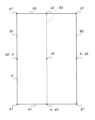
- FIG. 1 is a plane view conceptually showing a rectangular range used in a design method according to an embodiment of the present application.
- FIG. 13 is a plan view conceptually showing a method for determining a position for erecting a pillar in a design method according to one embodiment.
- FIG. 11 is a plan view showing a state in which a pillar has been written in a rectangular area in a design method according to one embodiment.
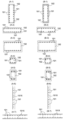
- FIG. 1 illustrates a column list, beam list, wall list, and slab list used in a design method according to one embodiment.
- 1 is a plan view conceptually showing a method for determining the placement positions of a frontage beam and a foundation frontage beam in a design method according to one embodiment.
- FIG. 1 is a plan view conceptually showing a method for determining the placement positions of a depth beam and a foundation depth beam in a design method according to one embodiment.
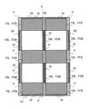
- FIG. FIG. 13 is a plan view conceptually showing a method for determining wall placement positions in a design method according to one embodiment.
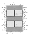
- FIG. 13 is a plan view conceptually showing another method for determining wall placement positions in a design method according to one embodiment.
- FIG. 13 is a plan view conceptually showing a method for determining the placement position of a slab in a design method according to one embodiment.
- FIG. 10 is a diagram showing the reinforced concrete structure designed as shown in FIG. 9 as viewed from the side in FIG. 9 .
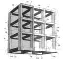
- FIG. 2 is a perspective view of an example of a frame of a reinforced concrete structure designed by a design method according to an embodiment.
- FIG. 11 is a perspective view of another example of a frame of a reinforced concrete structure designed by the design method according to one embodiment.
- design method for a reinforced concrete residential structure according to the present invention (hereinafter, simply referred to as the "design method") and the reinforced concrete residential structure designed by carrying out the design method.
- a reinforced concrete structure designed by this design method is designed based on a rectangular area ⁇ of a rectangle in a plan view as shown in FIG.
- the rectangular range ⁇ is a rectangular range in plan view defined by a frontage line segment A1 and a depth line segment B1 that are perpendicular to each other.
- the rectangular range ⁇ is a rectangle whose four sides are the frontage line segment A1, the depth line segment B1, the line segment A2, and the line segment B2.
- the frontage line segment A1 and the line segment A2 are opposite sides that are parallel to each other, and the depth line segment B1 and the line segment B2 are opposite sides that are parallel to each other.
- the frontage line segment A1, the line segment A2, the depth line segment B1, and the line segment B2 are all lines drawn on the ground on which the reinforced concrete structure is to be built.
- the frontage line segment A1 corresponds to one side of a reinforced concrete skeleton to be built later, which will be described later and will have a substantially rectangular parallelepiped shape, in a plan view
- the depth line segment B1 corresponds to the other side perpendicular to the frontage line segment A1 of the reinforced concrete skeleton.
- the frontage line segment A1 does not necessarily correspond to the frontage of the reinforced concrete skeleton to be built later, and the depth line segment B1 does not necessarily correspond to the depth of the reinforced concrete skeleton to be built later, but in this embodiment, the frontage line segment A1 corresponds to the frontage of the reinforced concrete skeleton to be built later, and the depth line segment B1 corresponds to the depth of the reinforced concrete skeleton to be built later.
- the frontage line segment A1 and the depth line segment B1 are appropriately determined according to the shape and size of the reinforced concrete skeleton to be built later, based on the shape and size of the site on which the reinforced concrete skeleton will be built. There may be cases where either the frontage line segment A1 or the depth line segment B1 is longer.
- the reinforced concrete structure constructed based on the above-mentioned rectangular range ⁇ includes a frame equipped with columns, front beams, front foundation beams, depth beams, and foundation depth beams. All of these are long materials, with the columns extending vertically, the front beams and front foundation beams extending horizontally in the front line direction, and the depth beams and foundation depth beams extending horizontally in the depth line direction.
- the position where the pillars are erected is determined by the following three rules, Rule 1 to Rule 3. Rules 1 to 3 will be explained with reference to Figs. 2 and 3. Rule 1)
- Rule 1 to 3 will be explained with reference to Figs. 2 and 3.
- Rule 1) The pillars P are erected at least on both ends of the two sides of the rectangular area ⁇ that are parallel to the depth line segment B1. In other words, the pillars are always erected at the four corners of the rectangular area ⁇ .
- the pillar P is erected at a depth division position b, which is a position on two sides that evenly divide the two sides parallel to the depth line segment B1 into lengths less than the first length.
- rule 3 When the frontage line segment A1 is longer than the second length, which is a predetermined length, pillars P are erected at both ends of auxiliary line segment B3, which is a virtual line segment of the same length as depth line segment B1 and extends parallel to depth line segment B1 from frontage division position a, which is a position on frontage line segment A1 that divides frontage line segment A1 evenly into lengths equal to or shorter than the second length, and at positions corresponding to depth division position b in the case that depth division position b exists on depth line segment B1.
- frontage division position a which is a position on frontage line segment A1 that divides frontage line segment A1 evenly into lengths equal to or shorter than the second length, and at positions corresponding to depth division position b in the case that depth division position b exists on depth line segment B1.
- rule 1 determines that pillars P are to be erected at four locations marked with p1.
- rule 2 the first length L1 appears (see FIG.
- the first length L1 is determined in advance when determining a reference frame, which will be described later.
- the first length L1 is determined in advance within a range of, for example, 4500 mm to 5700 mm. Although not limited to this, in this embodiment, the first length L1 is set to 5100 mm.
- the pillar P cannot be erected on the depth line segment B1 at any position other than p1 on both ends thereof, and the pillar P cannot be erected on the line segment B2 at any position other than p1 on both ends thereof.
- the length l1 of the depth line segment B1 is longer than the first length L1
- a pillar P is erected on the depth line segment B1 at the depth division position b in addition to the pillars p1 at both ends of the depth line segment B1.
- the depth division position b is a position at which the depth line segment B1 is divided when the depth line segment B1 is divided evenly by natural numbers as small as possible.
- the center of the depth line segment B1 becomes the depth division position b.
- the two positions that divide the depth line segment B1 into three equal parts become the depth division positions b.
- the n positions on the depth line segment B1 that divides the depth line segment B1 into n+1 equal parts become depth division positions b.
- the depth division position b is one location at the center of the depth line segment B1.
- the pillar P is erected at two locations: the center p2 of the depth line segment B1 and the center p2 of the line segment B2 parallel to the depth line segment B1.
- rule 3 the second length L2 appears (see FIG. 1).
- the second length L2 is determined in advance when determining the reference frame described later.
- the second length L2 can be determined in advance, for example, in the range of 3700 mm to 5100 mm. Although not limited to this, in this embodiment, the second length L2 is set to 4100 mm.
- the second length L2 can be different lengths depending on whether the reinforced concrete structure to be designed is for a detached house or for an apartment building.
- the second length L2 can be set to an appropriate length in the range of 4700 mm to 5100 mm (for example, 4900 mm), and when it is for an apartment building, the second length L2 can be set to an appropriate length in the range of 3700 mm to 4100 mm (for example, 3900 mm).
- the frontage division position a which is the position on the frontage line segment A1 that divides the frontage line segment A1 into equal parts of length equal to or less than the second length L2, is first obtained.
- the n positions on the frontage line segment A1 that divide the frontage line segment A1 into n+1 equal parts are the frontage division positions a.
- an auxiliary line segment B3 is obtained from there, which has a length equal to the depth line segment B1 and extends parallel to the depth line segment B1.
- the auxiliary line segment B3 is a line segment that connects the frontage line segment A1 and the line segment A2 so as to be perpendicular to both of them.
- the number of the auxiliary line segments B3 is n.
- the pillars P are erected at both ends p3 of the auxiliary line segment B3 and at a position p3 on the auxiliary line segment B3 that corresponds to the depth division position b.
- there is one frontage division position a and one auxiliary line segment B3 and the pillars P are erected at both ends p3 of the auxiliary line segment B3 and at the center p3 of the auxiliary line segment B3.
- FIG. 3 shows a case where it has been decided to erect pillars P at positions p1, p2, and p3 in the rectangular area ⁇ .
- the pillar P is rectangular in plan view, with the length in the depth direction (direction along the depth line segment B1) being longer than the length in the frontage direction (direction along the frontage line segment A1).
- the pillar P in this embodiment has a rectangular cross section with a length in the frontage direction of 400 mm and a length in the depth direction of 1200 mm.
- the numbers mentioned above for the first length L1 and the second length L2 are examples in which the cross-sectional shape of the pillar P is 400 mm x 1200 mm.
- Each column P has the same thickness and the same configuration of reinforcing bars in the longitudinal direction.
- the thickness or cross-sectional shape of each column P is the same in all parts in the longitudinal direction that are equal to or less than the third length, and the reinforcing bars arranged in the column P run inside the column P in the longitudinal direction.
- the third length can be determined, for example, as the upper limit assumed as the floor height per floor. That is, although all columns P in the reinforced concrete skeleton are limited to have a length equal to or less than the third length, the length does not need to be uniquely determined in advance.
- the configuration excluding the length of the column P in other words, the configuration per unit length, is standardized in a uniform manner.
- the length of the column P determines the floor height of the floor to which the column P belongs in the reinforced concrete skeleton
- the lengths of all columns P belonging to the same floor are made equal.
- the floor height of each floor of the reinforced concrete skeleton, which is a multi-story structure with multiple floors is the same.
- all columns P belonging to each floor of the reinforced concrete skeleton adopting a multi-story structure are assumed to have the same length.
- Fig. 4 (A-1) and (B-1) Examples of a column list showing the configuration of a column P used in a reinforced concrete skeleton are shown in Fig. 4 (A-1) and (B-1).
- Fig. 4 (A-1) shows a column list when the reinforced concrete skeleton is for a detached house
- Fig. 4 (B-1) shows a column list when the reinforced concrete skeleton is for an apartment building. All of the columns in the column list are cross-sectional views of the column P.
- 191 is a long reinforcing bar that runs in the length direction of the column P or in a direction perpendicular to the paper
- 192 is a loop-shaped reinforcing bar that surrounds the long reinforcing bar 191 to prevent the position from shifting.
- the dimensions of the column P excluding the length, and the configuration of the reinforcing bar (the arrangement position of the long reinforcing bar 191 including the number, the interval in the length direction of the reinforcing bar 191 where the loop-shaped reinforcing bar 192 is arranged, the type of the reinforcing bar 191, 192, etc.) are generally recorded. It is also possible to standardize the column list for detached houses and apartment buildings. While a large number of column lists are created for columns used in a typical concrete structure, rather than multiple, the number of column lists in this embodiment is small.
- the positions at which the frontage beams and foundation frontage beams are to be disposed are determined by the following two rules, Rule 4 to Rule 5. Rules 4 to 5 will be described with reference to FIG. Rule 4)
- the frontage beam FB is arranged so as to horizontally connect the upper and lower ends of all two columns P that are parallel to and adjacent to the frontage line segment A1, in a direction parallel to the frontage line segment A1.
- the foundation frontage beam FFB is positioned so as to horizontally connect the lower ends of all two columns P that are parallel to and adjacent to the frontage line segment A1, and that are in contact with the ground, in a direction parallel to the frontage line segment A1.
- a frontage beam FB or a foundation frontage beam FFB is stretched between two columns P arranged side by side in Fig. 5.
- Fig. 5 is a plan view, and the frontage beam FB and the foundation frontage beam FFB overlap each other. Both the frontage beam FB and the foundation frontage beam FFB are long.
- both the frontage beam FB and the foundation frontage beam FFB which is a type of frontage beam FB, have a rectangular cross section, and their width, which is their length in the depth direction, is set equal to the length in the depth direction of the column P.
- Both the frontage beam FB and the foundation frontage beam FFB are connected to the column P so that both ends in the width direction are aligned with both ends in the depth direction of the column P.
- Each front beam FB has the same thickness and the same configuration of the reinforcing bars in the longitudinal direction, as does the foundation front beam FFB.
- the front beam FB and the foundation front beam FFB have the same thickness or cross-sectional shape in all parts in the longitudinal direction, and the reinforcing bars arranged in the front beam FB or the foundation front beam FFB run inside them in the longitudinal direction.
- the length of all the frontage beams FB or foundation frontage beams FFB in the reinforced concrete structure must be equal to or less than the second length L2, the length does not need to be uniquely determined in advance.
- the configuration excluding the length of the frontage beams FB or foundation frontage beams FFB in other words, the configuration per unit length, is standardized in a uniform manner. Note that the length of multiple frontage beams FB that exist in one reinforced concrete structure is the same.
- the length of multiple foundation frontage beams FFB that exist is the same. Furthermore, the lengths of the frontage beams FB and the foundation frontage beams FFB are also the same. Examples of beam lists showing the configuration of the front beam FB used in a reinforced concrete structure are shown in Figures 4 (A-2), (A-3), (B-2), and (B-3).
- Figure 4 (A-2) shows a beam list of the front beam FB when the reinforced concrete structure is for a detached house
- (B-2) shows a beam list of the front beam FB when the reinforced concrete structure is for an apartment building.
- FIG. 4 shows a beam list of the foundation front beam FFB when the reinforced concrete structure is for a detached house
- (B-3) shows a beam list of the foundation front beam FFB when the reinforced concrete structure is for an apartment building.
- the above beam list shows a cross-sectional view of the frontage beam FB or foundation frontage beam FFB.
- 191 is a reinforcing bar running in the length direction of the frontage beam FB or foundation frontage beam FFB or in a direction perpendicular to the paper
- 192 is a loop-shaped reinforcing bar that surrounds the long reinforcing bar 191 to prevent their position from shifting.
- the dimensions of the frontage beam FB or foundation frontage beam FFB excluding the length, the configuration of the reinforcing bar (the arrangement position of the long reinforcing bar 191 including the number, the interval in the length direction of the reinforcing bar 191 where the loop-shaped reinforcing bar 192 is arranged, the type of the reinforcing bar 191, 192, etc.) are generally recorded. It is also possible to make the beam list for the frontage beam FB and foundation frontage beam FFB common to both detached houses and apartment buildings. Since the foundation front beam FFB is generally required to be stronger than the front beam FB, the thickness (or height) of the latter is made greater than the thickness of the former, regardless of whether it is for a detached house or an apartment building.
- a large number of beam lists are created for the frontage beams FB or foundation frontage beams FFB used in the structure, rather than multiple lists. In this embodiment, however, the number of beam lists for the frontage beams FB or foundation frontage beams FFB is small.
- the positions at which the depth beams and the foundation depth beams are disposed are determined by the following two rules, Rule 6 to Rule 7. Rules 6 to 7 will be described with reference to FIG. Rule 6)
- the depth beam DB is arranged so as to horizontally connect the upper and lower ends of all two columns P that are parallel to and adjacent to the depth line segment B1, in a direction parallel to the depth line segment B1.
- the foundation depth beam FDB is arranged so as to horizontally connect the lower ends of all two columns P that are parallel to and adjacent to the depth line B1, and that are in contact with the ground, in a direction parallel to the depth line B1. Please refer to Figure 6.
- a depth beam DB or a foundation depth beam FDB is stretched between two columns P located above and below in Fig. 6.
- Fig. 6 is a plan view, and the depth beam DB and the foundation depth beam FDB overlap each other.
- the depth beam DB and the foundation depth beam FDB are both long. However, their lengths are equal to or shorter than the first length L1, and are automatically determined by the positional relationship of the two columns P that are connected by them.
- the depth beam DB and the foundation depth beam FDB which is a type of depth beam DB, both have a rectangular cross section, and their width, which is the length in the frontage direction, is set equal to the length in the frontage direction of the column P.
- the depth beam DB and the foundation depth beam FDB are both connected to the column P so that both ends in the width direction are aligned with both ends in the frontage direction of the column P.
- Each depth beam DB has the same thickness and longitudinal rebar configuration, as does the foundation depth beam FDB.
- the thickness or cross-sectional shape of both the depth beam DB and the foundation depth beam FDB is the same throughout their length, and the rebars arranged within the depth beam DB or the foundation depth beam FDB run along their length. In other words, although there is a restriction that the length of all the depth beams DB or foundation depth beams FDB in a reinforced concrete structure must be equal to or less than the first length L1, the length does not need to be uniquely determined in advance.
- the configuration excluding the length of the depth beam DB or foundation depth beam FDB in other words, the configuration per unit length, is standardized in a uniform manner.
- the length of multiple depth beams DB that exist in one reinforced concrete structure is the same.
- the length of multiple foundation depth beams FDB that exist is the same.
- the lengths of the depth beams DB and foundation depth beams FDB are also the same. Examples of beam lists showing the configuration of the depth beam DB used for a reinforced concrete skeleton are shown in Figures 4 (A-4), (A-5), (B-4), and (B-5).
- Figure 4 (A-4) shows the beam list of the depth beam DB when the reinforced concrete skeleton is for a detached house
- Figure 4 (B-4) shows the beam list of the depth beam DB when the reinforced concrete skeleton is for an apartment building
- Figure 4 (A-5) shows the beam list of the foundation depth beam FDB when the reinforced concrete skeleton is for a detached house
- Figure 4 (B-5) shows the beam list of the foundation depth beam FDB when the reinforced concrete skeleton is for an apartment building.
- the above beam list shows a cross section of the depth beam DB or foundation depth beam FDB.
- 191 is a reinforcing bar running in the length direction of the depth beam DB or foundation depth beam FDB or in a direction perpendicular to the paper
- 192 is a loop-shaped reinforcing bar that surrounds the long reinforcing bar 191 to prevent their position from shifting.
- the dimensions of the depth beam DB or foundation depth beam FDB excluding the length, the configuration of the reinforcing bar (the arrangement position of the long reinforcing bar 191 including the number, the interval in the length direction of the reinforcing bar 191 where the loop-shaped reinforcing bar 192 is arranged, the type of the reinforcing bar 191, 192, etc.) are generally recorded.
- the beam list for the depth beam DB and the foundation depth beam FDB can be made common to both detached houses and apartment buildings. Since the foundation depth beam FDB generally requires greater strength than the depth beam DB, the latter is made thicker (or taller) than the former, regardless of whether it is for a detached house or an apartment building. In this embodiment, although not limited thereto, the thickness of the frontage beam FB and the depth beam DB are made the same, and the thickness of the foundation frontage beam FFB and the foundation depth beam FDB are made the same.
- a large number of beam lists for the depth beam DB or foundation depth beam FDB used in a typical concrete structure are created rather than multiple, but in this embodiment the number of beam lists for the depth beam DB or foundation depth beam FDB is small.
- the wall W fills the gap between adjacent columns P located on two sides parallel to the depth line segment B1 of the rectangular area ⁇ or on the auxiliary line segment B3.
- the walls W are rectangular.
- the walls W arranged according to rule 8 have four vertical sides connected to the columns P and two horizontal sides connected to the frontage beam FB or the foundation frontage beam FFB.
- the walls W are basically constructed on the frontage line segment A1 in the rectangular range ⁇ and the line segment A2 opposite the frontage line segment A1 (that is, on the contour of the rectangular range ⁇ ).
- the wall W may be arranged at a position that is inward from the frontage line segment A1 into the rectangular range ⁇ , as in the lower wall W in FIG. 8.
- the walls W may be designed to be arranged at a position away from the contour of the rectangular range ⁇ .
- six walls are arranged with their length direction being the vertical direction in Fig. 7 and Fig. 8.
- the walls W are rectangular.
- the walls W arranged according to rule 9 have four sides, two vertical sides connected to the columns P, and two horizontal sides connected to the depth beam DB or the foundation depth beam FDB. Even in this case, the walls W that are not on the auxiliary line segment B3 are allowed to be positioned outside the contour of the rectangular area ⁇ (i.e., a certain degree of freedom is given to the position of the walls W). However, in Fig. 7 and Fig. 8, the walls W are arranged on the contour of the rectangular area ⁇ , that is, on the depth line segment B1 and the line segment B2 that is the opposite side of the depth line segment B1. Whether the walls W are arranged according to rule 8 or 9, they are always plate-shaped, as is well known.
- the walls W are also standardized like the columns P, etc., so that they have the same structure per unit area.
- the walls W do not bear the role of supporting the weight of the reinforced concrete structure, so their robustness need only be at a minimum.
- Examples of wall lists showing the configuration of walls W used in a reinforced concrete skeleton are shown in Figures 4 (A-6) and (B-6).
- Figure 4 (A-6) shows a wall list of walls W when the reinforced concrete skeleton is for a single-family home
- Figure 4 (B-6) shows a wall list of walls W when the reinforced concrete skeleton is for an apartment building. All of the above wall lists are cross-sectional views of a wall W.
- 191 denotes reinforcing bars running in the wall W in the width direction or in the direction perpendicular to the paper surface.
- 191X denotes reinforcing bars running in the wall W parallel to the paper surface in the vertical direction relative to the paper surface.
- the wall list the dimensions of the wall (wall thickness) and the composition of the reinforcing bars (the spacing between reinforcing bars 191, 191X running in the width direction and height direction of the wall W, the type of reinforcing bars, etc.) are generally recorded. It is also possible to have a common wall list for walls W for detached houses and for apartment buildings.
- the position where the slab is placed is determined by the following rule 10.
- Rule 10 will be described with reference to Figs. Rule 10)
- the slab S horizontally fills a rectangular space surrounded by two front beams FB and two depth beams DB, or two foundation front beams FFB and two foundation depth beams FDB, at the height above and below the column P.
- Figure 10 is a diagram showing the reinforced concrete skeleton designed as shown in Figure 9, as viewed from the side in Figure 9. However, in Figure 10, the wall W is omitted.
- four slabs S are arranged in a 2x2 grid in Fig. 9.
- the slabs S are rectangular.
- the slabs S arranged according to rule 10 are horizontal and arranged above and below the columns P.
- the four sides of the slab S are connected to two front beams FB and two depth beams DB, or two foundation front beams FFB and two foundation depth beams FDB.
- all slabs S are plate-shaped.
- Slabs S are also standardized like columns P, etc., so that they have the same configuration per unit area. Since slabs S do not play a role in supporting the weight of the reinforced concrete structure, their robustness is only required to be at a minimum. Examples of slab lists showing the configuration of slabs S used in reinforced concrete structures are shown in Figures 4 (A-7) and (B-7).
- Figure 4 (A-7) shows a slab list for slabs S when the reinforced concrete structure is for a single-family home
- Figure 4 (B-7) shows a slab list for slabs S when the reinforced concrete structure is for an apartment building.
- All of the above slab lists are cross-sectional views of slab S.
- 191 denotes reinforcing bars that run through slab S in a direction perpendicular to the paper.
- 191X denotes reinforcing bars that run through slab S in a left-right direction parallel to the paper.
- Slab lists generally record the dimensions of the slab (slab thickness) and the configuration of reinforcing bars (the spacing and type of reinforcing bars 191, 191X that run perpendicular to each other through slab S, etc.). It is also possible to standardize slab lists for slabs S for single-family homes and apartment buildings.
- the top ends of the newly added columns P are connected with the front beams FB and depth beams DB, and the walls W and slabs S are placed.
- the walls W and slabs S are placed.
- the design of the reinforced concrete skeleton for a house is completed.
- the design order of the column P, frontage beam FB, foundation frontage beam FFB, depth beam DB, foundation depth beam FDB, wall W, and slab S does not have to be the order described above.
- it is not necessary to design the first floor before designing the second floor for example, the entire frame of a multi-story reinforced concrete structure may be designed first, and then the walls W and slabs S to be attached to the frame may be designed.
- the design of the holes for mounting the window frames and the holes for mounting the doors to be made in the wall W is omitted, and the design of the holes to be made in the slab S required to provide an internal staircase is omitted, but these can be designed in accordance with conventional technology.
- this reinforced concrete structure for example, it is possible to make one side of any of the walls W entirely made of glass. Even in this case, the walls W and slabs S do not bear the role of supporting the load of the reinforced concrete structure, so sufficient strength of the reinforced concrete structure is guaranteed.
- FIG. 11 and FIG. 11 and 12 are perspective views of a frame F in a reinforced concrete structure designed by the design method for a reinforced concrete structure described above.
- FIG. 11 of the two sides on the front side of the rectangular area ⁇ at the bottom edge of the frame F, the left side is a frontage line segment A1 and the right side is a depth line segment B1.
- the frontage line segment A1 is equal to or shorter than the second length L2, and the depth line segment B1 is more than twice the first length L1 and less than three times the first length L1.
- the frame F designed according to the above-mentioned rules 1 to 7 is as shown in Fig. 11.
- the rectangular parallelepiped area defined by the four columns P, four frontage beams FB (more precisely, two frontage beams FB and two foundation frontage beams FFB), and four depth beams DB (more precisely, two depth beams DB and two foundation depth beams FDB) shown in the shaded area in the figure corresponds to the reference frame SF explained in the overview of the present invention.
- the frame F shown in Fig. 11 is a combination of one reference frame SF in the frontage line segment A1 direction, three in the depth line segment B direction, and three in the vertical direction.
- FIG. 11 is a combination of one reference frame SF in the frontage line segment A1 direction, three in the depth line segment B direction, and three in the vertical direction.
- the right side is a frontage line segment A1 and the left side is a depth line segment B1.
- the frontage line segment A1 is longer than twice the second length L2 but shorter than three times the second length L2, and the depth line segment B1 is equal to or shorter than the first length L1.
- the frame F designed according to the above-mentioned rules 1 to 7 is as shown in Fig. 12.
- the frame shown in Fig. 12 is formed by lining up three reference frames SF explained in Fig. 11 in the direction of the frontage line segment A1, one in the direction of the depth line segment B, and three in the vertical direction.
- the columns P, frontage beams FB, foundation frontage beams FFB, depth beams DB, foundation depth beams FDB, walls W, and slabs S are connected together in X, Y, and Z numbers of reference frames SF in the frontage line direction, depth line direction, and vertical direction, respectively, to form a frame F having a generally rectangular parallelepiped shape as a whole (however, restrictions can be placed on the combinations of X, Y, and Z). Furthermore, even if walls W and slabs S are added to the frame F in accordance with rules 8 to 10 described above, the frame F is standardized so that it is sufficient to support the load of the entire reinforced concrete structure.
- the reinforced concrete structure having the frame F created by arranging the reference frame SF in the length, width, and height directions is guaranteed to have sufficient strength to support the load of the reinforced concrete structure.
- the above-mentioned column list specifying the configuration of the column P the above-mentioned beam list specifying the configuration of the front beam FB, the foundation front beam FFB, the depth beam DB, and the foundation depth beam FDB, the above-mentioned wall list specifying the configuration of the wall W, and the above-mentioned slab list specifying the configuration of the slab S are prepared in advance as a set in a state that satisfies the condition that the frame F is sufficient to support the load of the reinforced concrete structure when the reference frame SF is arranged in the length, width, and height directions, the frame F in the reinforced concrete structure created according to the above-mentioned rules 1 to 10 will automatically have sufficient strength to support the load of the reinforced concrete structure.
- the frame F in the reinforced concrete structure designed in this manner will have an approximately rectangular parallelepiped shape in which reference frames SF are stacked in the length, width, and height directions, or in which frames (quasi-reference frames described in the overview of the present invention) that are shorter than the reference frame SF in at least one of the length, width, and height directions are stacked in the length, width, and height directions.
- the reinforced concrete structure having the frame F shown in Figure 11 is suitable for a detached house equipped with an internal staircase connecting the first and second floors and an internal staircase connecting the second and third floors.
- two auxiliary line segments B3 are used.
- walls W are arranged on each of the first to third floors so as to divide each floor into three. Therefore, by providing an internal staircase connecting the first and second floors and an internal staircase connecting the second and third floors, the reinforced concrete structure having the frame F shown in Fig.
- the reinforced concrete structure having the frame shown in Fig. 12 can be suitable for an apartment building with a total of nine rooms, with three independent rooms on each floor.
- the reinforced concrete structure in this embodiment is constructed according to the design drawings designed by the design method described above.
- the reinforced concrete structure can be constructed using conventional construction methods. For example, in the case of a reinforced concrete structure for a one-story house, first the formwork is assembled and rebar is appropriately placed inside the formwork, and concrete is then poured into the assembled formwork and allowed to harden while curing, thereby constructing the foundation front beam FFB, foundation depth beam FDB, and slab S, which corresponds to the first floor floor. Next, the formwork assembled to construct the foundation front beam FFB and the foundation depth beam FDB is removed, and then the formwork is assembled again with appropriate rebar placed inside the formwork.
- Concrete is poured into the assembled formwork and cured while being hardened, thereby constructing the columns P, front beam FB, depth beam DB, walls W, and a slab S equivalent to the ceiling of the first floor.
- the formwork assembled to construct the columns P, front beams FB, depth beams DB, walls W, and slab S corresponding to the first floor ceiling of the first floor is removed, and then the formwork is assembled again and rebar is placed inside the formwork as appropriate.
- the reinforcing bars extending in the length direction of the column P, the reinforcing bars extending in the length direction of the frontage beam FB, and the reinforcing bars extending in the length direction of the depth beam DB, or the reinforcing bars extending in the length direction of the column P, the reinforcing bars extending in the length direction of the foundation frontage beam FFB, and the reinforcing bars extending in the length direction of the foundation depth beam FDB, are each made to intersect.
- the connections between the column P and the frontage beam FB, the column P and the depth beam DB, the column P and the foundation frontage beam FFB, and the column P and the foundation depth beam FDB can be strengthened, which helps to increase the resistance to load of the reinforced concrete structure.
- the long reinforcing bars 191 in the column P usually extend from the top to the bottom of the reinforced concrete skeleton.
- the ends of the reinforcing bars extending in the length direction of the frontage beam FB, the reinforcing bars extending in the length direction of the depth beam DB, the reinforcing bars extending in the length direction of the foundation frontage beam FFB, and the reinforcing bars extending in the length direction of the foundation depth beam FDB can all be inserted into the column P by an appropriate length, for example, about 400 mm.
- the portions of the reinforcing bars extending in the length direction of the frontage beam FB, the reinforcing bars extending in the length direction of the depth beam DB, the reinforcing bars extending in the length direction of the foundation frontage beam FFB, and the foundation depth beam FDB that enter the column P may be bent at right angles or folded back in a U-shape.
- each reinforcing bar is fixed at the parts where the reinforcing bars extending in the length direction of column P, the reinforcing bars extending in the length direction of front beam FB, and the reinforcing bars extending in the length direction of depth beam DB, or where the reinforcing bars extending in the length direction of column P, the reinforcing bars extending in the length direction of foundation front beam FFB, and the reinforcing bars extending in the length direction of foundation depth beam FDB, intersect.
Landscapes
- Engineering & Computer Science (AREA)
- Architecture (AREA)
- Physics & Mathematics (AREA)
- Electromagnetism (AREA)
- Civil Engineering (AREA)
- Structural Engineering (AREA)
- Foundations (AREA)
- Joining Of Building Structures In Genera (AREA)
Abstract
Description
本願発明は、住宅用の鉄筋コンクリート製躯体と、その設計方法に関する。住宅には、一戸建て住宅、集合住宅のいずれも含む。 This invention relates to a reinforced concrete structure for a house and its design method. The term "house" includes both detached houses and apartment buildings.
日本における住宅の躯体には主に、木造と鉄筋コンクリート製が存在する。近年、意匠性や堅牢性に富む鉄筋コンクリート製躯体を持つ住宅の人気が高まってきている。 In Japan, houses are primarily made of wood or reinforced concrete. In recent years, houses with reinforced concrete structures, which are stylish and durable, have become increasingly popular.
しかしながら、鉄筋コンクリート製躯体の住宅が木造の躯体の住宅を上回って普及するという状態にはなっていない。その大きな原因は、よく知られているように、鉄筋コンクリート製躯体の住宅を建築するために要する費用が、木造の躯体を持つ住宅の建築に要する費用よりも一般的に遥かに高価であるということにある。 However, houses with reinforced concrete structures have not yet become more popular than those with wooden structures. The main reason for this, as is well known, is that the cost of building a house with a reinforced concrete structure is generally much higher than the cost of building a house with a wooden structure.
鉄筋コンクリート製躯体の住宅を建築するために要する費用が高額となる理由には、鉄筋コンクリート製躯体の住宅を建築するために必要な資材の価格が、木造の躯体の住宅を建築するために必要な資材よりも高額となり易いということがある。
また、他の理由として、鉄筋コンクリート製躯体の住宅を建築するためには、構造設計を含む設計が必要となるところ、その費用は一般的に高価であるということもある。構造設計が高価になるのは一般に、構造設計が複雑であるからである。構造設計とは一般に、建物の土台と骨組みを様々な荷重に耐えられるように安全性能を満たしながら、経済的に設計することを意味する。
例えば、ラーメン構造の建築物の場合には、荷重を支えるのは、それぞれ複数の柱と梁である。多くの場合、建築資材の費用をなるべく低廉なものとするため、柱と梁の構造(例えば、柱や梁の太さや、それらの内部に配される鉄筋の位置、本数)は、柱ごと或いは梁ごとに異なることが殆どであり、むしろ、柱、梁の構造を柱ごと或いは梁ごとに異ならせるという複雑な構造を採用することにより、建築後の建物に求められる安全性能を充足させるということと、建築資材の費用をなるべく低廉にするということとを両立させるというのが通常である。現在では余りにも複雑になり過ぎた構造設計は殆どの場合、コンピュータにインストールされた専用のソフトウエアを用いて行われているが、専用のソフトウエアは上述の如きアプローチで作られている。
One reason why the cost of building a house with a reinforced concrete structure is so high is that the materials needed to build a house with a reinforced concrete structure tend to be more expensive than the materials needed to build a house with a wooden structure.
Another reason is that building a house with a reinforced concrete frame requires design, including structural design, which is generally expensive. Structural design is expensive because it is generally complex. Structural design generally means designing the foundation and framework of the building economically while meeting safety performance requirements so that it can withstand various loads.
For example, in the case of a rigid-frame structure, the load is supported by multiple columns and beams. In many cases, in order to keep the cost of construction materials as low as possible, the structure of columns and beams (for example, the thickness of the columns and beams, and the position and number of reinforcing bars arranged inside them) is almost always different for each column or beam, and it is more common to adopt a complex structure in which the structure of columns and beams is different for each column or beam, in order to achieve both the fulfillment of the safety performance required for the building after construction and the reduction of the cost of construction materials as low as possible. Nowadays, structural designs have become too complicated, and in most cases, they are performed using dedicated software installed on a computer, and the dedicated software is created using the approach described above.
上述したように、構造設計は極めて複雑である。それにより、別の問題も生じる。構造設計にあたって、構造設計者が行う作業は上述の説明から明らかなように極めて煩雑であり、そのため構造設計自体に要する時間が大きく、また構造設計に要する費用が比較的大きくなってしまうことが多い。例えば、鉄筋コンクリート製躯体の一戸建ての住宅の構造設計ですら、その期間に2ヶ月程度必要であり、50万円から100万円の費用がかかることが常識である。
しかも、構造設計が終わらないと、建築物を建築するために必要な建築資材が確定しないし、建築の工数(これは、建築の際に必要となる労務費に関係する)も確定しないため、建築物を建築するために必要な費用の見積りを行うことができない。そして、構造設計が終了した後に建築物を建築するために必要な費用の見積りが出たとしても、その費用が過大である場合には、施主はコンクリート製躯体の住宅の建築に着手するという決断を行うことができない。
構造設計が終わった後においてもそのようなリスクが存在するため、そもそも高額な費用が必要となる構造設計に着手することにも躊躇する施主が多い。
また、このような構造設計の複雑さは、実際に鉄筋コンクリート製躯体を建築する際の労務費を増大させる。例えば、各柱毎、各梁毎にその構成が異なるのであれば、コンクリート型枠の内部に鉄筋を配する作業は各柱毎、各梁毎に異なるものとなるので、作業の難易度が高くなり、作業効率が落ちたりミスが生じたりする原因にもなる。
このような事情も、コンクリート製躯体の住宅の普及を妨げている。
As mentioned above, structural design is extremely complicated. This causes other problems. As is clear from the above explanation, the work done by structural designers is extremely complicated, and therefore the time required for structural design itself is long and the cost required for structural design is often relatively high. For example, it is common knowledge that the structural design of even a detached house with a reinforced concrete frame takes about two months and costs 500,000 to 1,000,000 yen.
Furthermore, until the structural design is complete, the materials needed to build the building and the number of construction steps (which relate to the labor costs required during construction) are not finalized, and so the cost required to build the building cannot be estimated. Even if an estimate of the cost required to build the building is available after the structural design is complete, if the cost is excessive, the client will not be able to make the decision to start construction of a house with a concrete frame.
Because such risks exist even after the structural design has been completed, many clients are hesitant to even begin structural design, which requires a large amount of expense.
Furthermore, the complexity of such structural designs increases the labor costs when actually constructing a reinforced concrete structure. For example, if the structure of each column and each beam is different, the work of placing rebar inside the concrete formwork will be different for each column and each beam, which increases the difficulty of the work, leading to reduced work efficiency and the occurrence of errors.
These circumstances also hinder the spread of concrete-structured homes.
少なくとも構造設計を簡単にすることができれば、例えばそれにより構造設計の費用を抑制することができれば、コンクリート製躯体の住宅の普及を妨げている上述の課題の一部が解決される可能性がある。
しかしながら、構造設計が「構造設計とは一般に、建物の土台と骨組みを様々な荷重に耐えられるように安全性能を満たしながら、経済的に設計する」という目的を持つものであり、「柱、梁の構造を柱ごと或いは梁ごとに異ならせるという複雑な構造を採用することにより、建築後の建物に求められる安全性能を充足させるということと、建築資材の費用をなるべく低廉にするということとを両立させる」というのがその目的を達成するための正しいアプローチであると信じられている現状では、構造設計を簡単にするという発想自体が存在していない。したがって、構造設計を安価に行えるようにするための現実的な手段は少なくとも現時点では提案されていない。
If structural design could be simplified, for example by reducing costs, it could potentially resolve some of the issues preventing the widespread use of concrete-framed homes.
However, in the current situation where structural design has the objective of "generally designing the foundations and framework of a building economically while satisfying safety performance so that it can withstand various loads," and where it is believed that the correct approach to achieve this objective is to "achieve both the satisfaction of the safety performance required for the building after construction and the reduction of construction material costs as much as possible by adopting a complex structure in which the structures of columns and beams are different for each column or beam," the idea of simplifying structural design does not even exist. Therefore, at least at present, no realistic means have been proposed to make structural design cheaper.
本願発明は、構造設計を簡単なものにすることにより、構造設計を短期間で安価にすることを可能とする技術であり、場合によっては住宅を建築するために必要な費用をも安価にすることのできる技術を提案することをその課題とする。その技術は、もっぱら、住宅用の鉄筋コンクリート製躯体、或いは設計方法に関する。 The present invention aims to propose a technology that simplifies structural design, making it possible to complete the design in a short time and at a low cost, and in some cases, even reducing the costs required to build a house. The technology is concerned exclusively with reinforced concrete frameworks for houses, or design methods.
以上の課題を解決するために本願出願人が提案する発明について、まず概説する。
従来の構造設計は既に述べたように複雑である。構造設計が複雑になるのは、例えば、ラーメン構造の構成要素である、柱、梁等に、必要最低限の強度しか与えないことにより、柱、梁によって与えられる建物或いは住宅の強度を確保することと、建築資材の費用を最小限に抑えることとを両立しようとするためである。柱、梁に必要最低限の強度しか与えないようにするため、鉄筋コンクリート製躯体中の異なる位置にある柱や梁にそれぞれ異なる構成を与えることが必要となり、その結果、構造設計が複雑なものとなる。建築物において、それぞれの柱の太さやその内部に含まれる鉄筋の数が異なることが普通であり、また、同一の柱の柱の高さ位置ごとに柱の太さや鉄筋の数が異なることも良くある。
他方、建物或いは住宅における荷重を柱と梁で支えるラーメン構造において最も単純な形状は、フレームを直方体形状とした場合である。直方体形状のフレームには、いずれも水平で互いに直交するx方向とy方向とに4本ずつそれぞれ伸びる梁と、鉛直なz方向に4本伸びる柱とが含まれる。
そのような直方体形状のフレームのうち、所定の形状であるものを基準となるフレームである基準フレームとして定め、そして、その基準フレームをx方向、y方向、z方向に連ねていく(或いは、配列していく)ことによって、直方体形状の新たなフレームを構築することを考える。隣接する基準フレームのうち、互いに重なり合う柱同士、梁同士は、一本にまとめることとする。それにより、ある程度の自由度をもって、直方体形状のフレームを構築することが可能となる。
次に、基準フレームを連結することによって作られる直方体形状のフレームに、壁とスラブを加えて鉄筋コンクリート製躯体を得る場合について考える。ただし、上述の基準フレームをz方向のみ20段積み重ねて新たなフレームを構築するようなある意味非常識なフレームについては考えない。そのような非常識ではない、別の言葉でいえば、設計者が予定している範囲での基準フレームの配列を行った場合、例えば、x方向にX個、y方向にY個、z方向にZ個の基準フレームの配列を行った場合であって、その新たなフレームに更に壁とスラブを加えた場合を考える。柱、梁、壁、スラブは、鉄筋コンクリートによって作られる鉄筋コンクリート製躯体の構成要素である。
予定された範囲において基準フレームを積み重ねることによって作られた新たなフレームが、必ずそのフレームを含む鉄筋コンクリート製躯体を有する住宅の荷重を支えることができるように、基準フレームにおける柱と、梁の構成を規格化することが可能である。ただし、梁のうち、最も下の地面に接する梁は基礎を兼ねさせるために、他の梁と異なる規格を与えるようにする。
そうすると、基準フレームを、x方向にX個、y方向にY個、z方向にZ個配列する(ただし、許容されるX、Y、Zの組合せは、設計者等によって事前に決定されている。)ことによって得られる新たなフレームを含む鉄筋コンクリート製躯体は、新たな構造設計或いは構造計算をするまでもなく、その鉄筋コンクリート製躯体を有する住宅の荷重を必ず支えられるものとなる。
とはいえ、この場合には、基準フレームに含まれる柱や梁の構成は、基準フレームを配列して作られた新たなフレームが住宅の荷重を支えるために必要とされる性能以上の性能を備えている場合がままあるであろう。
加えて、規格化された上述の如き柱と梁とを含む基準フレームを、x方向にX個、y方向にY個、z方向にZ個配列する(ただし、上述したように、許容されるX、Y、Zの組合せは、設計者等によって事前に決定されている。)ことによって得られる新たなフレームを含む鉄筋コンクリート製躯体がそれを含む住宅の荷重を必ず支えられることが保証されているのであれば、規格化された柱と梁に準じた柱と梁を備える基準フレームよりも例えばx方向、y方向、z方向の少なくとも1方向において小さくしたフレームである基準フレームに準拠したフレーム(準基準フレーム)を、x方向にX個、y方向にY個、z方向にZ個配列することによって得られる新たなフレームを含む鉄筋コンクリート製躯体もまた、新たな構造設計或いは構造計算をするまでもなく、その鉄筋コンクリート製躯体を有する住宅の荷重を必ず支えられるものとなる。
この場合には、準基準フレームに含まれる柱や梁の構成は、準基準フレームを配列して作られた新たなフレームが住宅の荷重を支えるために必要とされる性能以上の性能を備えている場合が更に頻発するであろう。
しかしながら、柱と梁に以上で説明したような過剰性能を与えることを許容するとともに、住居の形状を直方体形状(後述するように、完全な直方体形状とは限られない。)とするという制限を許容することにすれば、構造設計は極めて簡単になり、構造設計に要する時間も費用も抑制可能となる。
また、従来の設計方法では厳密な構造設計後にしか行うことのできなかった、コンクリート製躯体の建築を行うことに対する見積りも、短時間で行うことのできる構造設計の終了後に即座に行うことができるようになる。
更に、構造設計を簡単なものとする過程で、柱、梁が規格化されたものとなった鉄筋コンクリート製躯体は、実際に鉄筋コンクリート製躯体を建築する際の作業難易度を下げることにより建築の作業効率を向上させることを可能とし、結果として労務費の削減を可能とする場合がある。加えて、規格化された柱毎或いは規格化された梁毎に共通することとなった建築用の資材(例えば鉄筋)の大量購入により資材の仕入れ費用を抑制することも可能となる場合がある。これらを加味すれば、構造設計を簡単なものとした本願発明によれば、簡単な構造設計によって設計される鉄筋コンクリート製躯体を建築するための費用(構造設計から鉄筋コンクリート製躯体を建築するまでのトータルの費用)は、柱や梁に過剰性能を与えることによる費用の増加分を考慮したとしても、従来よりも安くなる場合が多く存在する。
本願発明は、このような考え方によりなされた。
The invention proposed by the applicant to solve the above problems will first be outlined.
As already mentioned, conventional structural design is complicated. The reason why structural design becomes complicated is, for example, to ensure the strength of the building or house provided by the columns and beams by giving only the minimum necessary strength to the components of the rigid frame structure, such as columns and beams, while minimizing the cost of construction materials. In order to give only the minimum necessary strength to the columns and beams, it is necessary to give different structures to the columns and beams at different positions in the reinforced concrete structure, which results in a complicated structural design. In a building, it is common for the thickness of each column and the number of reinforcing bars contained therein to differ, and it is also common for the thickness and number of reinforcing bars to differ at different height positions of the same column.
On the other hand, the simplest shape for a rigid frame structure in which the load of a building or house is supported by columns and beams is a rectangular parallelepiped frame, which includes four beams each extending in the horizontal and mutually perpendicular x- and y-directions, and four columns extending in the vertical z-direction.
Among such rectangular parallelepiped frames, we define a frame with a specific shape as a reference frame, and then we consider constructing a new rectangular parallelepiped frame by connecting (or arranging) the reference frames in the x, y, and z directions. Among adjacent reference frames, columns and beams that overlap each other are combined into one. This makes it possible to construct a rectangular parallelepiped frame with a certain degree of freedom.
Next, consider the case where walls and slabs are added to a rectangular frame made by connecting reference frames to obtain a reinforced concrete structure. However, we will not consider a frame that is somewhat unconventional, such as stacking the above-mentioned reference frames 20 times in the z direction only to construct a new frame. We will consider a case where the reference frames are arranged within the range planned by the designer, for example, X number of reference frames in the x direction, Y number in the y direction, and Z number in the z direction, and walls and slabs are further added to the new frame. Columns, beams, walls, and slabs are components of a reinforced concrete structure made of reinforced concrete.
It is possible to standardize the structure of columns and beams in a standard frame so that a new frame created by stacking standard frames within a planned range can always support the weight of a house with a reinforced concrete structure that includes that frame. However, among the beams, the beam that comes into contact with the ground at the bottom is given a different standard from the other beams so that it also serves as the foundation.
In this way, a reinforced concrete structure including a new frame obtained by arranging X reference frames in the x direction, Y frames in the y direction, and Z frames in the z direction (the allowable combinations of X, Y, and Z are determined in advance by a designer or the like) will be able to support the load of a house having that reinforced concrete structure without the need for new structural design or calculations.
However, in this case, the configuration of columns and beams included in the reference frame will often have performance that exceeds that required for the new frame created by arranging the reference frames to support the load of the house.
In addition, if it is guaranteed that a reinforced concrete structure including a new frame obtained by arranging X pieces of reference frames including the above-mentioned standardized columns and beams in the x direction, Y pieces in the y direction, and Z pieces in the z direction (however, as described above, the allowable combinations of X, Y, and Z are determined in advance by a designer or the like), can always support the load of a house including it, then a reinforced concrete structure including a new frame obtained by arranging X pieces of frames (quasi-reference frames) in the x direction, Y pieces in the y direction, and Z pieces in the z direction, which conform to a reference frame that is smaller in at least one of the x direction, y direction, and z direction than a reference frame equipped with columns and beams similar to the standardized columns and beams, will also be able to always support the load of a house having that reinforced concrete structure, without the need for a new structural design or structural calculation.
In this case, it will become more common for the configuration of columns and beams included in the quasi-reference frame to have a performance that exceeds the performance required for supporting the load of the house when the new frame is created by arranging the quasi-reference frames.
However, if it is permitted to give the columns and beams the excessive performance described above, and if the shape of the dwelling is restricted to a rectangular prism (which, as will be described later, does not have to be a perfect rectangular prism), the structural design becomes extremely simple, and the time and cost required for the structural design can be reduced.
In addition, estimates for constructing a concrete structure, which could only be made after rigorous structural design in the conventional design method, can now be made immediately after the structural design is completed, which can be done in a short time.
Furthermore, in the process of simplifying the structural design, the reinforced concrete skeleton with standardized columns and beams can improve the efficiency of construction work by reducing the difficulty of work when actually constructing the reinforced concrete skeleton, which may result in a reduction in labor costs. In addition, it may be possible to reduce the cost of purchasing materials by purchasing construction materials (e.g., reinforcing bars) in bulk that are common to each standardized column or beam. Taking these factors into consideration, according to the present invention in which the structural design is simplified, the cost of constructing a reinforced concrete skeleton designed with a simple structural design (the total cost from structural design to constructing the reinforced concrete skeleton) is often lower than before, even taking into account the increase in cost due to the excessive performance of the columns and beams.
The present invention was made based on this idea.
本願発明は、以下のような住宅用の鉄筋コンクリート製躯体(以下、単に「鉄筋コンクリート製躯体」という場合もある。)として実現される。
本願発明の鉄筋コンクリート製躯体は、間口方向に伸びる所定の長さの仮想の線分である間口線分と、前記間口線分の一端から前記間口線分と垂直な方向に伸びる所定の長さの仮想の線分である奥行線分とによって規定される平面視矩形の範囲である矩形範囲を基準として構築される。
本願発明による鉄筋コンクリート製躯体は、上述の矩形範囲の前記奥行線分に平行な2辺上の少なくとも両端と、所定の長さである第1長さより長い場合における前記奥行線分に平行な2辺を前記第1長さ以下の長さに均等に区切る前記2辺上の位置である奥行区分位置と、に対として立てられるとともに、所定の長さである第2長さより長い場合における前記間口線分を前記第2長さ以下に均等に区切る前記間口線分上の位置である間口区分位置から前記奥行線分に平行に伸びる前記奥行線分と同じ長さの仮想の線分である補助線分の両端と、前記補助線分上の前記奥行区分位置に対応する位置とに立てられた、所定の長さである第3長さ以下の長さの鉛直な長尺材である複数の柱を有する。
また、本願発明による鉄筋コンクリート製躯体は、前記柱のうち、前記間口線分に平行で且つ隣接する位置にあるもの2本のすべての上下の両端部を、前記間口線分と平行な方向で水平に繋ぐ長尺材である複数の間口梁、及び前記間口梁のうち地面に接する複数の基礎間口梁を有する。
また、前記柱のうち、前記奥行線分に平行で且つ隣接する位置にあるもの2本のすべての上下の両端部を前記奥行線分と平行な方向で水平に繋ぐ長尺材である複数の奥行梁、及び前記奥行梁のうち地面に接する複数の基礎奥行梁を有する。
また、本願発明による鉄筋コンクリート製躯体は、前記矩形範囲の前記間口線分に平行な2辺上に位置する前記柱のうち、隣接するもの同士の間を前記間口線分に平行に板状に塞ぐか、又は前記矩形範囲の前記奥行線分に平行な2辺或いは前記補助線分上に位置する前記柱のうち、隣接するもの同士の間を前記奥行線分に平行に板状に塞ぐ複数の壁を有する。
また、本願発明による鉄筋コンクリート製躯体は、前記柱の上下の高さ位置において、2本の前記間口梁と2本の前記奥行梁、又は2本の前記基礎間口梁と2本の前記基礎奥行梁とに囲まれる矩形の空間を水平に塞ぐ複数のスラブを有する。
そして、前記柱、前記間口梁、前記基礎間口梁、前記奥行梁、及び前記基礎奥行梁のみによって構成されるフレームの構造設計上の強度が十分となるようにされている。
また、本願発明における住宅用の鉄筋コンクリート製躯体における複数の前記柱はすべて、太さと長さ方向の鉄筋の構成が同一であり、複数の前記間口梁はすべて、太さと長さ方向の鉄筋の構成が同一であり、複数の前記基礎間口梁はすべて、太さと長さ方向の鉄筋の構成が同一であり、複数の前記奥行梁はすべて、太さと長さ方向の鉄筋の構成が同一であり、複数の前記基礎奥行梁はすべて、太さと長さ方向の鉄筋の構成が同一であり、複数の前記壁はすべて、所定の単位面積あたりの構成が同一であり、複数の前記スラブはすべて、所定の単位面積あたりの構成が同一である。
The present invention is realized as a reinforced concrete structure for a house (hereinafter sometimes simply referred to as a "reinforced concrete structure") as described below.
The reinforced concrete structure of the present invention is constructed based on a rectangular area, which is a rectangular area in a plan view defined by a frontage line, which is a virtual line segment of a predetermined length extending in the frontage direction, and a depth line, which is a virtual line segment of a predetermined length extending from one end of the frontage line in a direction perpendicular to the frontage line.
The reinforced concrete structure of the present invention has a plurality of columns which are vertical, elongated members having a length equal to or less than a predetermined third length, which are erected in pairs at least both ends of two sides parallel to the depth line segment of the above-mentioned rectangular range, and at depth division positions which are positions on the two sides that evenly divide the two sides parallel to the depth line segment into lengths equal to or less than the first length when the two sides are longer than a predetermined first length, and which are also erected at both ends of an auxiliary line segment which is a virtual line segment of the same length as the depth line segment and extends parallel to the depth line segment from a frontage division position which is a position on the frontage line segment that evenly divides the frontage line segment into lengths equal to or less than the second length when the frontage line segment is longer than a predetermined second length, and at positions corresponding to the depth division positions on the auxiliary line segment.
In addition, the reinforced concrete structure of the present invention has a plurality of frontage beams, which are long members that horizontally connect the upper and lower ends of all two of the columns that are parallel to and adjacent to the frontage line, in a direction parallel to the frontage line, and a plurality of foundation frontage beams that are in contact with the ground among the frontage beams.
In addition, the system includes a plurality of depth beams which are long members that horizontally connect the upper and lower ends of all two of the columns that are parallel to and adjacent to the depth line in a direction parallel to the depth line, and a plurality of foundation depth beams which are in contact with the ground among the depth beams.
In addition, the reinforced concrete structure of the present invention has a plurality of walls that seal the gap between adjacent columns located on two sides parallel to the frontage line of the rectangular area in a plate-like manner parallel to the frontage line, or that seal the gap between adjacent columns located on two sides parallel to the depth line of the rectangular area or on the auxiliary line in a plate-like manner parallel to the depth line.
In addition, the reinforced concrete structure of the present invention has a plurality of slabs that horizontally fill a rectangular space surrounded by two of the front beams and two of the depth beams, or two of the foundation front beams and two of the foundation depth beams, at height positions above and below the columns.
The structural design strength of the frame formed only by the columns, the frontage beams, the foundation frontage beams, the depth beams, and the foundation depth beams is ensured to be sufficient.
In addition, in the reinforced concrete structure for a house in the present invention, all of the multiple columns have the same thickness and longitudinal reinforcing bar configuration, all of the multiple frontage beams have the same thickness and longitudinal reinforcing bar configuration, all of the multiple foundation frontage beams have the same thickness and longitudinal reinforcing bar configuration, all of the multiple depth beams have the same thickness and longitudinal reinforcing bar configuration, all of the multiple foundation depth beams have the same thickness and longitudinal reinforcing bar configuration, all of the multiple walls have the same configuration per specified unit area, and all of the multiple slabs have the same configuration per specified unit area.
本願発明による鉄筋コンクリート製躯体は、矩形範囲を基準として構築される。矩形範囲は、平面視矩形の範囲である。矩形範囲は、平面視した場合に互いに直交する2つの線分によってその平面形状を規定される。2つの線分の一方は間口線分であり、他方が奥行線分である。なお、最終的に構築された住宅の間口線分に対応する部分がその住宅の間口に相当するとは限らず、奥行線分についても同様である。
鉄筋コンクリート製躯体は、上述した基準フレームに相当する直方体形状のフレームを縦横高さ方向に少なくとも1つ配列することによって構築されたフレームを有している。フレームを構築するのは、柱と、間口梁と、奥行梁である。それらはいずれも複数であり、少なくとも4本ずつである。なお、間口梁のうち地面に接するものは基礎間口梁であり、奥行梁のうち地面に接するものは基礎奥行梁である。基礎間口梁と基礎奥行梁は、基礎を兼ねる。
柱は、上述の矩形範囲の奥行線分に平行な2辺上の少なくとも両端に立設される。言い換えれば、柱は、矩形範囲の4隅に必ず立てられる。柱は、また、奥行線分が所定の長さである第1長さより長い場合には、奥行線分に平行な2辺を第1長さ以下の長さに均等に区切る当該2辺上の位置である奥行区分位置にも立てられる。柱は、また、間口線分が所定の長さである第2長さより長い場合には、間口線分を第2長さ以下の長さに均等に区切る間口線分上の位置である間口区分位置から奥行線分に平行に伸びる奥行線分と同じ長さの仮想の線分である補助線分を想定した場合における、補助線分の両端と、奥行線分上に奥行区分位置が存在する場合における奥行区分位置に対応する位置とにも立てられる。柱は鉛直であり、また、その長さは所定の長さである第3長さ以下である。
間口梁と、基礎間口梁とは以下のようなものとされる。間口梁は、柱のうち、間口線分に平行で且つ隣接する位置にあるもの2本のすべての上下の両端部を、間口線分と平行な方向で水平に繋ぐ。間口梁は、長尺材である。間口梁のうち地面に接するものが基礎間口梁である。上述したように、間口梁が張り渡される間口線分に平行な直線上に位置する隣接する2本の柱の間隔は第2長さ以下であるのだから、間口梁(と基礎間口梁)の長さは必ず第2長さ以下となる。
奥行梁と、基礎奥行梁とは以下のようなものとされる。奥行梁は、柱のうち、奥行線分に平行で且つ隣接する位置にあるもの2本のすべての上下の両端部を奥行線分と平行な方向で水平に繋ぐ長尺材である。奥行梁のうち地面に接するものが基礎奥行梁である。上述したように、奥行梁が張り渡される奥行線分に平行な直線上に位置する隣接する2本の柱の間隔は第1長さ以下であるのだから、奥行梁(と基礎奥行梁)の長さは必ず第1長さ以下となる。
壁は複数であり、矩形範囲の間口線分に平行な2辺上に位置する柱のうち、隣接するもの同士の間を間口線分に平行に板状に塞ぐか、又は矩形範囲の奥行線分に平行な2辺或いは補助線分上に位置する柱のうち、隣接するもの同士の間を奥行線分に平行に板状に塞ぐ。
スラブは、複数であり、柱の上下の高さ位置において、2本の間口梁と2本の奥行梁、又は2本の基礎間口梁と2本の基礎間口梁とに囲まれる矩形の空間を水平に塞ぐ。スラブは、屋上、或いは床を構成する。
加えて、複数の柱はすべて、太さと長さ方向の鉄筋の構成が同一であり、複数の間口梁はすべて、太さと長さ方向の鉄筋の構成が同一であり、複数の基礎間口梁はすべて、太さと長さ方向の鉄筋の構成が同一であり、複数の奥行梁はすべて、太さと長さ方向の鉄筋の構成が同一であり、複数の前記基礎奥行梁はすべて、太さと長さ方向の鉄筋の構成が同一である。つまり、柱、間口梁(及び基礎間口梁)、奥行梁(及び基礎奥行梁)はすべて、規格化されている。その規格化は、柱、間口梁、基礎間口梁、奥行梁、及び基礎奥行梁のみによって構成されるフレームの構造設計上の強度が十分となるように設計されている。
この鉄筋コンクリート製躯体は、フレームによって荷重に耐える構成を採用している。つまり、壁とスラブは、荷重を担う機能を有する必要がない。言い換えれば、本願の鉄筋コンクリート製躯体は、いわゆるラーメン構造を採用したものとなっている。
フレームは、4本の柱と、4本の間口梁(又は2本の間口梁と2本の基礎間口梁)、4本の奥行梁(又は2本の奥行梁と2本の基礎奥行梁)で構成される、上述の本願発明の概説で説明した基準フレームを、x方向(例えば間口線分方向)、y方向(例えば奥行線分方向)に配列したものとなる。また、既に述べたように、柱の長さは第3長さ以下であり、間口梁(及び基礎間口梁)の長さは第2長さ以下であり、奥行梁(及び基礎奥行梁)の長さは第1長さ以下となる。
ここで、柱、間口梁(及び基礎間口梁)、奥行梁(及び基礎奥行梁)はそれぞれ、太さと長さ方向の鉄筋の構成が規格化されている。この規格化は、柱、間口梁、基礎間口梁、奥行梁、及び基礎奥行梁のみによって構成されるフレームの構造設計上の強度が十分となるように設計されている。そのような規格化された柱、間口梁(及び基礎間口梁)、及び奥行梁(及び基礎奥行梁)がそれぞれ満たすべき条件は、本願発明の概説で説明した基準フレームを、x、y、z方向の長さがそれぞれ、第1長さ(最長の奥行梁又は基礎奥行梁の長さ)、第2長さ(最長の間口梁又は基礎間口梁の長さ)、第3長さ(最長の柱の長さ)とした場合において、その基準フレームを、x、y、z方向にX、Y、Z個(ただし、許容されるX、Y、Zの組合せは、設計者等によって事前に決定されている。)配列することによって得られるフレームを含む鉄筋コンクリート製躯体が、そのフレームによって鉄筋コンクリート製躯体全体の荷重を支えることができるようにするための条件として、容易に求めることができる。
本願の鉄筋コンクリート製躯体に含まれることになるフレームは、上述したような基準フレームを、x、y方向、或いはx、y、z方向に配列したものとなるか、或いは上述したような基準フレームよりもx、y、z方向の少なくとも1方向の長さが短くされた基準フレームをx、y方向、或いはx、y、z方向に配列したものとなる。いずれの場合においても、そのようなフレームを含む鉄筋コンクリート製躯体は、それに含まれるフレームのみによって、新たな構造設計を行うまでもなく、鉄筋コンクリート製躯体全体の荷重に耐えられるものとなる。
したがって、本願の鉄筋コンクリート製躯体は、その構造設計が簡単となり、構造設計に要する時間も費用も抑制可能となる。また、このような鉄筋コンクリート製躯体は、短時間で行うことのできる構造設計後速やかに見積を行うことができることになる。
加えて、柱、間口梁及び基礎間口梁、奥行梁と基礎奥行梁のそれぞれを規格化してそれぞれ、長さを除いて同一構造とするとともに、壁やスラブの構造も規格化することにより、鉄筋コンクリート製躯体の構築時において必要となる、コンクリートを流し込むための型枠を組む作業や、型枠の中に鉄筋を配する配筋の作業を画一的なものとすることが可能となる。これは、上述した鉄筋コンクリート製躯体を有する住宅を建築するための作業を容易にするものであり、鉄筋コンクリート製躯体を建築するための費用の抑制に繋がる。
また、柱、間口梁及び基礎間口梁、奥行梁と基礎奥行梁のそれぞれを規格化してそれぞれ、長さを除いて同一構造とするとともに、壁やスラブの構造も規格化するということを、1つの鉄筋コンクリート製躯体についてではなく、多数の鉄筋コンクリート製躯体について行うことにより、例えば、鉄筋コンクリート製躯体を建築するときに柱等の中に入れることが必要となる鉄筋の種類を最小限とすることも可能である。そうすると、建築資材の小品種大量仕入れが可能となるため、本願の鉄筋コンクリート製躯体を建築するために必要となる建築資材の仕入れコストを抑制することも可能となる。
The reinforced concrete skeleton of the present invention is constructed based on a rectangular area. The rectangular area is a rectangular area when viewed from above. The planar shape of the rectangular area is defined by two lines that are perpendicular to each other when viewed from above. One of the two lines is a frontage line, and the other is a depth line. Note that the part of the house that corresponds to the frontage line of the house that is finally constructed does not necessarily correspond to the frontage of the house, and the same applies to the depth line.
The reinforced concrete structure has a frame constructed by arranging at least one rectangular parallelepiped frame corresponding to the reference frame described above in the length, width, and height directions. The frame is constructed of columns, front beams, and depth beams. There are multiple of each, at least four of each. The front beams that come into contact with the ground are foundation front beams, and the depth beams that come into contact with the ground are foundation depth beams. The foundation front beams and foundation depth beams also serve as the foundation.
The pillars are erected at least at both ends of the two sides parallel to the depth line segment of the rectangular range. In other words, the pillars are always erected at the four corners of the rectangular range. When the depth line segment is longer than a first length, which is a predetermined length, the pillars are also erected at a depth division position, which is a position on the two sides that divides the two sides parallel to the depth line segment into lengths equal to or less than the first length. When the frontage line segment is longer than a second length, which is a predetermined length, the pillars are also erected at both ends of the auxiliary line segment, which is a virtual line segment of the same length as the depth line segment that extends parallel to the depth line segment from the frontage division position, which is a position on the frontage line segment that divides the frontage line segment into lengths equal to or less than the second length, and at a position corresponding to the depth division position when the depth division position exists on the depth line segment. The pillars are vertical, and their length is equal to or less than a third length, which is a predetermined length.
The frontage beam and foundation frontage beam are as follows. The frontage beam horizontally connects the upper and lower ends of all two columns that are parallel to the frontage line and adjacent to each other in a direction parallel to the frontage line. The frontage beam is a long material. The frontage beam that comes into contact with the ground is the foundation frontage beam. As mentioned above, the distance between two adjacent columns located on a straight line parallel to the frontage line across which the frontage beam is stretched is less than the second length, so the length of the frontage beam (and foundation frontage beam) is always less than the second length.
The depth beam and foundation depth beam are defined as follows. The depth beam is a long material that horizontally connects both the upper and lower ends of all two columns that are parallel to the depth line and adjacent to each other in a direction parallel to the depth line. The depth beam that comes into contact with the ground is the foundation depth beam. As described above, the distance between two adjacent columns located on a straight line parallel to the depth line across which the depth beam is stretched is equal to or less than the first length, so the length of the depth beam (and foundation depth beam) is always equal to or less than the first length.
There are multiple walls, and among the columns located on two sides parallel to the frontage line of the rectangular area, the gap between adjacent columns is sealed with a plate-like material parallel to the frontage line, or among the columns located on two sides or an auxiliary line parallel to the depth line of the rectangular area, the gap between adjacent columns is sealed with a plate-like material parallel to the depth line.
There are multiple slabs, and they horizontally fill a rectangular space surrounded by two front beams and two depth beams, or two foundation front beams and two foundation front beams, at the height above and below the columns. The slab forms the roof or floor.
In addition, all of the columns have the same thickness and longitudinal rebar configuration, all of the front beams have the same thickness and longitudinal rebar configuration, all of the foundation front beams have the same thickness and longitudinal rebar configuration, all of the depth beams have the same thickness and longitudinal rebar configuration, and all of the foundation depth beams have the same thickness and longitudinal rebar configuration. In other words, the columns, front beams (and foundation front beams), and depth beams (and foundation depth beams) are all standardized. This standardization is designed so that the structural design strength of the frame composed only of the columns, front beams, foundation front beams, depth beams, and foundation depth beams is sufficient.
This reinforced concrete structure uses a frame to withstand loads. In other words, the walls and slabs do not need to support loads. In other words, the reinforced concrete structure of the present application uses a rigid frame structure.
The frame is a reference frame described in the above-mentioned overview of the present invention, which is composed of four columns, four front beams (or two front beams and two foundation front beams), and four depth beams (or two depth beams and two foundation depth beams), and is arranged in the x direction (e.g., the front line direction) and the y direction (e.g., the depth line direction). As already mentioned, the length of the columns is equal to or less than the third length, the length of the front beams (and the foundation front beams) is equal to or less than the second length, and the length of the depth beams (and the foundation depth beams) is equal to or less than the first length.
Here, the thickness and longitudinal configuration of the reinforcing bars of the columns, front beams (and foundation front beams), and depth beams (and foundation depth beams) are standardized. This standardization is designed so that the structural strength of the frame composed only of the columns, front beams, foundation front beams, depth beams, and foundation depth beams is sufficient. The conditions that such standardized columns, frontage beams (and foundation frontage beams), and depth beams (and foundation depth beams) must satisfy can be easily determined as conditions for a reinforced concrete structure including a frame obtained by arranging X, Y, and Z pieces of the reference frame described in the overview of the present invention in the x, y, and z directions (however, the allowable combinations of X, Y, and Z are determined in advance by a designer, etc.) in the x, y, and z directions, so that the frame can support the load of the entire reinforced concrete structure.
The frame to be included in the reinforced concrete structure of the present application is a reference frame as described above arranged in the x- and y-directions, or in the x-, y- and z-directions, or a reference frame shorter in length in at least one of the x-, y- and z-directions than the reference frame as described above arranged in the x- and y-directions, or in the x-, y- and z-directions. In either case, a reinforced concrete structure including such a frame can withstand the load of the entire reinforced concrete structure by the frame included therein alone, without the need for a new structural design.
Therefore, the structural design of the reinforced concrete structure of the present invention is simplified, and the time and cost required for the structural design can be reduced. In addition, such a reinforced concrete structure can be estimated promptly after the structural design, which can be completed in a short time.
In addition, by standardizing the columns, frontage beams, foundation frontage beams, depth beams and depth beams of the foundation to have the same structure except for their length, and also standardizing the structure of the walls and slabs, it becomes possible to standardize the work of constructing the formwork into which the concrete is poured and the work of placing the reinforcing bars in the formwork, which are necessary when constructing a reinforced concrete structure. This makes it easier to build a house with the above-mentioned reinforced concrete structure, and leads to a reduction in the cost of building a reinforced concrete structure.
Furthermore, by standardizing the columns, frontage beams, foundation frontage beams, depth beams and foundation depth beams to have the same structure except for their lengths, and also standardizing the structures of the walls and slabs, not for one reinforced concrete structure but for many reinforced concrete structures, it is possible to minimize the types of rebar that need to be inserted in columns, etc., when constructing a reinforced concrete structure. This makes it possible to purchase a small variety of building materials in large quantities, and therefore makes it possible to reduce the purchasing costs of building materials required to construct the reinforced concrete structure of the present application.
前記間口線分は、第2長さ以下である場合がある。
その場合、上述した矩形範囲の中に補助線分が存在しないことになり、柱は、矩形範囲を囲む辺の上のみに存在することになる。そのような鉄筋コンクリート製躯体は、一戸建ての住居に向いたものとなる。
他方、前記間口線分は、前記第2長さ以下の場合がある。この場合、前記補助線分で区切られた隣接する2つの空間は、他の住宅を構成するようになっていてもよい。
その場合、上述した矩形範囲の中には、少なくとも一本の補助線分が存在することになり、柱は、矩形範囲を囲む辺の上のみならず、補助線分の両端部と、場合によっては補助線分の途中に存在することになる。その場合においては、矩形範囲は、補助線分上に設けられる壁によって区切られることになる。そのような鉄筋コンクリート製躯体は、アパート、マンションその他の集合住宅に向いたものとなる。
なお、上述したように、本願発明による鉄筋コンクリート製躯体では、柱、間口梁及び基礎間口梁、奥行梁と基礎奥行梁のそれぞれの構造と、壁やスラブの構造も規格化する。規格化された柱、間口梁及び基礎間口梁、奥行梁と基礎奥行梁、壁、スラブのセットを、一戸建て住宅を意図した鉄筋コンクリート製躯体用に一セット、集合住宅を意図した鉄筋コンクリート製躯体用に一セット、互いに異なるものとして予め準備して置くこともできる。
なお、第1長さ、第2長さ、第3長さのセットも、戸建住宅用と集合住宅用とで、異なるセットを準備しておいても良い。
The frontage segment may be equal to or less than a second length.
In this case, there will be no auxiliary line segments within the above-mentioned rectangular area, and the columns will only be on the sides that enclose the rectangular area. Such a reinforced concrete structure is suitable for a detached house.
On the other hand, the frontage line segment may be equal to or shorter than the second length. In this case, the two adjacent spaces separated by the auxiliary line segment may constitute another residence.
In this case, at least one auxiliary line segment will exist within the above-mentioned rectangular range, and columns will exist not only on the sides surrounding the rectangular range, but also on both ends of the auxiliary line segment, and in some cases, in the middle of the auxiliary line segment. In this case, the rectangular range will be divided by walls built on the auxiliary line segment. Such a reinforced concrete structure is suitable for apartments, condominiums, and other collective housing.
As described above, in the reinforced concrete skeleton of the present invention, the structures of the columns, front beams and foundation front beams, depth beams and foundation depth beams, as well as the structures of the walls and slabs are standardized. Sets of standardized columns, front beams and foundation front beams, depth beams and foundation depth beams, walls, and slabs can be prepared in advance as different sets, one set for a reinforced concrete skeleton intended for a detached house and another set for a reinforced concrete skeleton intended for an apartment building.
In addition, different sets of the first length, second length, and third length may be prepared for detached houses and for apartment buildings.
本願発明による鉄筋コンクリート製躯体では、すべての前記柱の上に、前記第3長さ以下とされ、太さと長さ方向の鉄筋の構成が前記柱と同一とされた新たな柱である延長柱少なくとも1本が、すべての前記柱に対して同数ずつ鉛直方向に延長して接続されていてもよい。この場合、前記間口梁、前記奥行梁、前記壁、前記スラブとそれぞれ同じ構成の新たな前記間口梁、前記奥行梁、前記壁、前記スラブの組が、延長された前記1本分の柱毎に設けられていることで、前記住宅が多層階構造となっていてもよい。
このように鉄筋コンクリート製躯体は、一戸建て用、集合住宅用の別を問わず、多層階の住宅用のものとすることができる。
この場合、延長柱は、柱と同様に規格化されたものとなる。また、延長柱の長さは、柱と同様に第3長さ以下の長さとされる。したがって、多層階に対応した鉄筋コンクリート製躯体であっても、本願発明の概説で述べた理由により、従来よりも簡単な構造設計により設計された鉄筋コンクリート製躯体であっても、それに含まれるフレームにより鉄筋コンクリート製躯体全体の荷重に耐えられることが保証される。
延長柱の長さは、1階の柱の長さと等しくても良い。そうすると、延長柱と柱は、長さも含めて同じ構成となり、多層階に対応した鉄筋コンクリート製躯体における各階の階高は同じとなる。これは、鉄筋コンクリート製躯体の構造設計をより単純化することにも寄与するし、また、型枠の設置や配筋の作業をより画一化することにも寄与する。
In the reinforced concrete skeleton according to the present invention, at least one extension column, which is a new column having a length equal to or less than the third length and a thickness and longitudinal rebar configuration identical to that of the columns, may be connected to each of the columns by extending the same number of columns vertically. In this case, a new set of the front beam, the depth beam, the wall, and the slab having the same configuration as the front beam, the depth beam, the wall, and the slab, respectively, may be provided for each extended column, so that the house has a multi-story structure.
In this way, reinforced concrete structures can be used for multi-story residential buildings, whether single-family homes or apartment buildings.
In this case, the extension column is standardized in the same way as the column. Also, the length of the extension column is set to be equal to or less than the third length, in the same way as the column. Therefore, even if the reinforced concrete structure is for a multi-story building, or if the reinforced concrete structure is designed with a simpler structural design than the conventional structure, due to the reasons described in the overview of the present invention, the frame included therein ensures that the reinforced concrete structure can withstand the load of the entire structure.
The length of the extension column can be the same as the length of the column on the first floor. In that case, the extension column and the column will have the same structure, including the length, and the floor height of each floor in a reinforced concrete structure that supports multiple floors will be the same. This contributes to simplifying the structural design of the reinforced concrete structure and also contributes to standardizing the installation of formwork and the work of arranging reinforcement.
本願発明の鉄筋コンクリート製躯体における柱は、太さと長さ方向の鉄筋の構成が同一とされ、規格化される。柱は、その全長において同じ太さで同じ断面形状を持つものとされる。
前記柱は、例えば、前記間口方向の長さよりも前記奥行方向の長さの方が長い平面視矩形とすることができる。そうすることにより、柱に、壁の一部を担わせることが可能となるとともに、鉄筋コンクリート製躯体の荷重に耐える性能を柱に与えやすくなる。
柱の形状が上述したような平面視矩形の場合、前記間口梁の前記奥行方向の長さである幅は、前記柱の前記奥行方向の長さに等しくされていてもよい。基礎間口梁も同様とすることができる。そうすることにより、間口梁(と基礎間口梁)の幅を柱に接続可能な範囲で最大とすることができるため、間口梁(と基礎間口梁)による、鉄筋コンクリート製躯体の荷重を支える効果を最大化できることになるとともに、柱と、間口梁(と基礎間口梁)との接続部分の美観をすっきりしたものとすることができるようになる。また、間口梁(と基礎間口梁)と柱との接合を強固なものとするためには、間口梁(と基礎間口梁)の内部をそれらの長さ方向に走る鉄筋を柱の内部にまで至らせるのが望ましいが、間口梁(と基礎間口梁)の幅を柱の奥行方向の長さに一致させ、間口梁(と基礎間口梁)の幅方向を柱の奥行方向に対応させれば、断面のどこに位置していたとしても、間口梁(と基礎間口梁)の内部にある鉄筋を柱の内部に入れ込むことが可能となる。
また、柱の形状が上述したような平面視矩形の場合、前記奥行梁の前記間口方向の長さである幅は、前記柱の前記間口方向の長さに等しくされていてもよい。基礎奥行梁も同様とすることができる。そうすることにより、奥行梁(と基礎奥行梁)の幅を柱に接続可能な範囲で最大とすることができるため、奥行梁(と基礎奥行梁)による、鉄筋コンクリート製躯体の荷重を支える効果を最大化できることになるとともに、柱と奥行梁(と基礎奥行梁)の少なくとも一方との接続部分の美観をすっきりしたものとすることができるようになる。また、奥行梁(と基礎奥行梁)と柱との接合を強固なものとするためには、奥行梁(と基礎奥行梁)の内部をそれらの長さ方向に走る鉄筋を柱の内部にまで至らせるのが望ましいが、奥行梁(と基礎奥行梁)の幅を柱の間口方向の長さに一致させ、奥行梁(と基礎奥行梁)の幅方向を柱の間口方向に対応させれば、断面のどこに位置していたとしても、奥行梁(と基礎奥行梁)の内部にある鉄筋を柱の内部に入れ込むことが可能となる。
The columns in the reinforced concrete structure of the present invention are standardized with the same thickness and longitudinal rebar configuration. The columns are assumed to have the same thickness and cross-sectional shape along their entire length.
The pillars may be rectangular in plan view, for example, with the depth longer than the width, allowing the pillars to support part of the wall and making it easier to provide the pillars with the ability to withstand the load of the reinforced concrete framework.
In the case where the shape of the column is a rectangle in plan view as described above, the width of the frontage beam, which is the length in the depth direction, may be equal to the length of the column in the depth direction. The same can be done for the foundation frontage beam. By doing so, the width of the frontage beam (and the foundation frontage beam) can be maximized within the range that can be connected to the column, which maximizes the effect of the frontage beam (and the foundation frontage beam) in supporting the load of the reinforced concrete structure, and also makes it possible to neaten the aesthetic appearance of the connection part between the column and the frontage beam (and the foundation frontage beam). In addition, in order to strengthen the connection between the frontage beams (and foundation frontage beams) and the columns, it is desirable to have the reinforcing bars running along the length of the interior of the frontage beams (and foundation frontage beams) extend to the inside of the columns; however, if the width of the frontage beams (and foundation frontage beams) is made to match the depth direction of the columns and the width direction of the frontage beams (and foundation frontage beams) corresponds to the depth direction of the columns, it will be possible to insert the reinforcing bars inside the frontage beams (and foundation frontage beams) into the interior of the columns, regardless of where they are located in the cross section.
In addition, when the shape of the column is a rectangle in plan view as described above, the width of the depth beam, which is the length in the frontage direction, may be equal to the length of the column in the frontage direction. The same can be done for the foundation depth beam. By doing so, the width of the depth beam (and foundation depth beam) can be maximized within the range that can be connected to the column, so that the effect of supporting the load of the reinforced concrete body by the depth beam (and foundation depth beam) can be maximized, and the aesthetic appearance of the connection part between the column and at least one of the depth beam (and foundation depth beam) can be made neat. In addition, in order to strengthen the connection between the depth beam (and foundation depth beam) and the column, it is desirable to make the reinforcing bars running in the length direction of the depth beam (and foundation depth beam) reach the inside of the column, but if the width of the depth beam (and foundation depth beam) is made to match the length of the column in the frontage direction and the width direction of the depth beam (and foundation depth beam) corresponds to the frontage direction of the column, it is possible to insert the reinforcing bars inside the depth beam (and foundation depth beam) into the column, regardless of where they are located in the cross section.
本願発明者は、また、鉄筋コンクリート製躯体の設計方法も本願発明の一態様として提案する。かかる設計方法の発明の効果は、本願の住宅用の鉄筋コンクリート製躯体を設計することができるというものである。その設計に基づいて建築される鉄筋コンクリート製躯体は、これまでに述べた鉄筋コンクリート製躯体が奏する効果を奏する。
一例となる住宅用の鉄筋コンクリート製躯体の設計方法は、間口方向に伸びる所定の長さの仮想の線分である間口線分と、前記間口線分の一端から前記間口線分と垂直な方向に伸びる所定の長さの仮想の線分である奥行線分とによって規定される平面視矩形の範囲である矩形範囲を基準として、鉛直に立てられた、所定の長さである第3長さ以下の長さの長尺材である、長さを除いて構成が同一とされた柱、複数と、前記間口線分に平行な仮想の同一の線分の上にある隣接する前記柱2本の上下の両端部を水平に繋ぐ複数の間口梁、及び前記間口梁のうち地面に接する複数の基礎間口梁と、前記奥行線分に平行な仮想の同一の線分の上にある隣接する前記柱2本の上下の両端部を水平に繋ぐ複数の奥行梁、及び前記奥行梁のうち地面に接する複数の基礎奥行梁と、前記柱のうち、所定の2本の間を塞ぐ板状の複数の壁と、前記柱の上下の高さ位置において、2本の前記間口梁と2本の前記奥行梁、又は2本の前記基礎間口梁と2本の前記基礎奥行梁とに囲まれる矩形の空間を水平に塞ぐ板状の複数のスラブと、を組合せることによって構成される住宅用の鉄筋コンクリート製躯体を、前記柱の太さと長さ方向の鉄筋の構成、前記間口梁、前記基礎間口梁、前記奥行梁、及び前記基礎奥行梁それぞれの太さと長さ方向の鉄筋の構成、前記壁、及び前記スラブの単位面積あたりの構成をそれぞれ、前記柱、前記間口梁、前記基礎間口梁、前記奥行梁、及び前記基礎奥行梁のみによって構成されるフレームの構造設計上の強度が十分となる範囲で規格化して決定した上で設計する、鉄筋コンクリート製躯体の設計方法である。
そして、その設計方法は、前記間口線分と、前記奥行線分とのそれぞれの長さを決定する過程と、前記矩形範囲の前記奥行線分に平行な2辺上の少なくとも両端と、所定の長さである第1長さより長い場合における前記奥行線分に平行な前記2辺を前記第1長さ以下の長さに均等に区切る前記2辺上の位置である奥行区分位置と、に対として前記柱を立てるとともに、所定の長さである第2長さより長い場合における前記間口線分を前記第2長さ以下に均等に区切る前記間口線分上の位置である間口区分位置から前記奥行線分に平行に伸びる前記奥行線分と同じ長さの仮想の線分である補助線分の両端と、前記補助線分上の前記奥行区分位置に対応する位置とに規格化された前記柱を立てることを決定する過程と、前記柱のうち、前記間口線分に平行で且つ隣接する位置にあるもの2本のすべての上下の両端部を規格化された前記間口梁、又は前記基礎間口梁で繋ぐことを決定する過程と、前記柱のうち、前記奥行線分に平行で且つ隣接する位置にあるもの2本のすべての上下の両端部を規格化された前記奥行梁、又は前記基礎奥行梁で繋ぐことを決定する過程と、前記矩形範囲の前記間口線分に平行な2辺上に位置する前記柱のうち、隣接するもの同士の間を前記間口線分に平行な規格化された前記壁によって塞ぐこと、及び前記矩形範囲の前記奥行線分に平行な2辺或いは前記補助線分上に位置する前記柱のうち、隣接するもの同士の間を前記奥行線分に平行な規格化された前記壁によって塞ぐことを決定する過程と、前記柱の上下の高さ位置において、2本の前記間口梁と2本の前記奥行梁、又は2本の前記基礎間口梁と2本の前記基礎奥行梁とに囲まれる平面視矩形の空間を規格化された前記スラブによって塞ぐことを決定する過程と、を含む。
The present inventor also proposes a method for designing a reinforced concrete structure as one aspect of the present invention. The effect of the invention of the design method is that it is possible to design the reinforced concrete structure for the house of the present application. The reinforced concrete structure constructed based on the design achieves the effects of the reinforced concrete structure described above.
An example of a design method for a reinforced concrete skeleton for a house includes, based on a rectangular range that is a rectangular range in a plan view defined by a frontage line, which is a virtual line segment of a predetermined length extending in the frontage direction, and a depth line, which is a virtual line segment of a predetermined length extending from one end of the frontage line in a direction perpendicular to the frontage line, a plurality of columns that are elongated members having a length equal to or less than a third length that is a predetermined length and that are erected vertically and have the same configuration except for their length, a plurality of frontage beams that horizontally connect both upper and lower ends of two adjacent columns on the same virtual line segment that is parallel to the frontage line, and a plurality of foundation frontage beams that contact the ground among the frontage beams, a plurality of depth beams that horizontally connect both upper and lower ends of two adjacent columns on the same virtual line segment that is parallel to the depth line, and a plurality of foundation depth beams that contact the ground among the depth beams. and a plurality of plate-shaped walls that fill the space between two predetermined ones of the columns, and a plurality of plate-shaped slabs that horizontally fill a rectangular space surrounded by two of the front beams and two of the depth beams, or two of the foundation front beams and two of the foundation depth beams, at the height positions above and below the columns, the reinforced concrete structure for a house is designed after standardizing and determining the thickness and longitudinal reinforcement configuration of the columns, the thickness and longitudinal reinforcement configuration of each of the front beams, the foundation front beams, the depth beams, and the foundation depth beams, and the configuration per unit area of the walls and the slabs within a range in which the structural design strength of the frame composed only of the columns, the front beams, the foundation front beams, the depth beams, and the foundation depth beams is sufficient.
The design method includes a process of determining the length of each of the frontage line segment and the depth line segment, a process of erecting the columns in pairs at least both ends on two sides of the rectangular area parallel to the depth line segment and at a depth division position that is a position on the two sides that divides the two sides parallel to the depth line segment evenly into lengths equal to or less than the first length when the length is longer than a first length, which is a predetermined length, and a process of deciding to erect the columns standardized at both ends of an auxiliary line segment that is a virtual line segment of the same length as the depth line segment and extends from the frontage division position that is a position on the frontage line segment that divides the frontage line segment evenly into lengths equal to or less than the second length when the length is longer than a second length, which is a predetermined length, to a position corresponding to the depth division position on the auxiliary line segment, and a process of deciding to erect the columns standardized at both ends of the upper and lower ends of all two of the columns that are parallel to the frontage line segment and adjacent to it. the steps of determining to connect the upper and lower ends of all two of the columns that are parallel to the depth line and adjacent to each other with the standardized depth beams or the foundation depth beams; determining to seal the space between adjacent ones of the columns located on two sides parallel to the frontage line of the rectangular area with the standardized walls parallel to the frontage line, and determining to seal the space between adjacent ones of the columns located on two sides parallel to the depth line of the rectangular area or on the auxiliary line with the standardized walls parallel to the depth line; and determining to seal a rectangular space in plan view surrounded by the two frontage beams and two depth beams, or two foundation frontage beams and two foundation depth beams, at the height positions above and below the columns, with the standardized slab.
以下図面を参照しつつ、本願発明による住宅用の鉄筋コンクリート製躯体の設計方法(以下、単に「設計方法」という場合がある。)と、その設計方法を実行することによって設計された住宅用の鉄筋コンクリート製躯体について説明する。 With reference to the drawings, we will now explain the design method for a reinforced concrete residential structure according to the present invention (hereinafter, simply referred to as the "design method") and the reinforced concrete residential structure designed by carrying out the design method.
≪設計方法≫
かかる設計方法によって設計される鉄筋コンクリート製躯体は、図1に示したような平面視矩形の矩形範囲αを基準として設計される。
矩形範囲αは、互いに垂直な間口線分A1と、奥行線分B1とによって規定される平面視矩形の範囲である。矩形範囲αは、間口線分A1、奥行線分B1、線分A2、線分B2を4辺とする矩形である。間口線分A1と線分A2とは、互いに平行な対辺であり、奥行線分B1と線分B2とは、互いに平行な対辺である。概念としては、間口線分A1、線分A2、奥行線分B1、線分B2はいずれも、鉄筋コンクリート製躯体が建てられる地面に描かれる線分である。
間口線分A1は、後に建てられる、追って説明するが略直方体形状とされる鉄筋コンクリート製躯体の平面視した場合の一辺を、奥行線分B1は、鉄筋コンクリート製躯体の間口線分A1と垂直な他の一辺に相当するものである。間口線分A1が、後に建てられる鉄筋コンクリート製躯体の間口に相当する必要はないし、奥行線分B1が、後に建てられる鉄筋コンクリート製躯体の奥行に相当する必要はないが、この実施形態では、間口線分A1は、後に建てられる鉄筋コンクリート製躯体の間口に相当し、奥行線分B1が、後に建てられる鉄筋コンクリート製躯体の奥行に相当するようにする。
間口線分A1と、奥行線分B1とは、鉄筋コンクリート製躯体が建てられる敷地の形状、大きさ等に基づいて、後に建てられる鉄筋コンクリート製躯体の形状、大きさに合わせて適宜決定される。間口線分A1と奥行線分B1の長さはどちらが長い場合もあり得る。
<Design method>
A reinforced concrete structure designed by this design method is designed based on a rectangular area α of a rectangle in a plan view as shown in FIG.
The rectangular range α is a rectangular range in plan view defined by a frontage line segment A1 and a depth line segment B1 that are perpendicular to each other. The rectangular range α is a rectangle whose four sides are the frontage line segment A1, the depth line segment B1, the line segment A2, and the line segment B2. The frontage line segment A1 and the line segment A2 are opposite sides that are parallel to each other, and the depth line segment B1 and the line segment B2 are opposite sides that are parallel to each other. Conceptually, the frontage line segment A1, the line segment A2, the depth line segment B1, and the line segment B2 are all lines drawn on the ground on which the reinforced concrete structure is to be built.
The frontage line segment A1 corresponds to one side of a reinforced concrete skeleton to be built later, which will be described later and will have a substantially rectangular parallelepiped shape, in a plan view, and the depth line segment B1 corresponds to the other side perpendicular to the frontage line segment A1 of the reinforced concrete skeleton. The frontage line segment A1 does not necessarily correspond to the frontage of the reinforced concrete skeleton to be built later, and the depth line segment B1 does not necessarily correspond to the depth of the reinforced concrete skeleton to be built later, but in this embodiment, the frontage line segment A1 corresponds to the frontage of the reinforced concrete skeleton to be built later, and the depth line segment B1 corresponds to the depth of the reinforced concrete skeleton to be built later.
The frontage line segment A1 and the depth line segment B1 are appropriately determined according to the shape and size of the reinforced concrete skeleton to be built later, based on the shape and size of the site on which the reinforced concrete skeleton will be built. There may be cases where either the frontage line segment A1 or the depth line segment B1 is longer.
上述の矩形範囲αを基準として建築される鉄筋コンクリート製躯体は、柱と、間口梁と、間口基礎梁と、奥行梁と、基礎奥行梁とを備えたフレームを含むものとされる。それらはいずれも長尺材であり、柱は鉛直方向に、間口梁、及び間口基礎梁は間口線分方向に水平に、奥行梁、及び基礎奥行梁は奥行線分方向に水平にそれぞれ伸びる。 The reinforced concrete structure constructed based on the above-mentioned rectangular range α includes a frame equipped with columns, front beams, front foundation beams, depth beams, and foundation depth beams. All of these are long materials, with the columns extending vertically, the front beams and front foundation beams extending horizontally in the front line direction, and the depth beams and foundation depth beams extending horizontally in the depth line direction.
まず、矩形範囲αに対する、柱の建てられる位置をどのようにして決定するかについて説明する。
柱の建てられる位置は、以下のルール1からルール3の3つのルールによって決まる。図2、図3を用いて、ルール1からルール3について説明する。
ルール1)柱Pは、上述の矩形範囲αの奥行線分B1に平行な2辺上の少なくとも両端に立設される。言い換えれば、柱は、矩形範囲αの4隅に必ず立てられる。
ルール2)柱Pは、奥行線分B1が所定の長さである第1長さより長い場合には、奥行線分B1に平行な2辺を第1長さ以下の長さに均等に区切る当該2辺上の位置である奥行区分位置bに立てられる。
ルール3)柱Pは、間口線分A1が所定の長さである第2長さより長い場合には、間口線分A1を第2長さ以下の長さに均等に区切る間口線分A1上の位置である間口区分位置aから奥行線分B1に平行に伸びる奥行線分B1と同じ長さの仮想の線分である補助線分B3を想定した場合における、補助線分B3の両端と、奥行線分B1上に奥行区分位置bが存在する場合における奥行区分位置bに対応する位置とに立てられる。
図2を参照する。
まず、ルール1によって、p1の符号が付された4箇所に柱Pが立てられることが決定される。
次にルール2についてである。ルール2では、第1長さL1が登場する(図1参照)。第1長さL1は、後述する基準フレームを決定する際に予め決定されている。第1長さL1は、例えば4500mmから5700mmの範囲で予め決定しておく。これには限られないがこの実施形態では、第1長さL1を5100mmと定めている。
ルール2により立てられる柱Pの位置を決定するには、まず、奥行線分B1の長さl1が、第1長さL1よりも長いか否かを検証する。奥行線分B1の長さl1が、第1長さL1以下の場合には、奥行線分B1の上には、その両端のp1以外の位置に柱Pは立てられず、また、線分B2の上には、その両端のp1以外の位置に柱Pは立てられない。
他方、奥行線分B1の長さl1が、第1長さL1よりも長い場合には、奥行線分B1の上には、その両端のp1に加え、奥行区分位置bにも柱Pが立てられる。奥行区分位置bは、なるべく小さい自然数で奥行線分B1を均等に区分した場合における、奥行線分B1を区分する位置である。例えば、奥行線分B1を2等分した場合における長さが第1長さL1以下となった場合には、奥行線分B1の中央が、奥行区分位置bとなる。また、奥行線分B1を2等分した場合における長さが第1長さL1よりも長く、奥行線分B1を3等分した場合における長さが第1長さL1以下となった場合には、奥行線分B1を3等分する2つの位置が、奥行区分位置bとなる。より一般化するのであれば、奥行線分B1をn等分した場合における長さが第1長さL1よりも長く、奥行線分B1をn+1等分した場合における長さが第1長さL1以下となった場合には、奥行線分B1をn+1等分する奥行線分B1上のn個の位置が、奥行区分位置bとなる。
図2に示した例では、奥行区分位置bが、奥行線分B1の中央の1箇所である場合が示されている。その場合、ルール2に従って柱Pは、奥行線分B1の中央p2と、奥行線分B1と平行な線分B2の中央p2との2箇所に立てられることになる。
次にルール3についてである。ルール3には、第2長さL2が登場する(図1参照)。第2長さL2は、後述する基準フレームを決定する際に予め決定されている。第2長さL2は、例えば、3700mmから5100mmの範囲で予め決定しておくことができる。これには限られないがこの実施形態では、第2長さL2を4100mmと定めている。なお、第2長さL2は、設計の対象となる鉄筋コンクリート製躯体が一戸建て用の場合と、集合住宅用の場合とで異なる長さとすることも可能である。例えば、鉄筋コンクリート製躯体が一戸建て用の場合には第2長さL2を4700mmから5100mmの範囲の適当な長さ(例えば、4900mm)とし、集合住宅用の場合には第2長さL2を3700mmから4100mmの範囲の適当な長さ(例えば、3900mm)と決定しておくことができる。
ルール3により立てられる柱Pの位置を決定するには、まず、間口線分A1の長さl2が、第2長さL2よりも長いか否かを検証する。間口線分A1の長さl2が、第2長さL2以下の場合には、ルール3により立てられる柱Pは存在しない。
他方、間口線分A1が所定の長さである第2長さL2より長い場合には、間口線分A1を第2長さL2以下の長さに均等に区切る間口線分A1上の位置である間口区分位置aをまず求めることになる。奥行線分B1を均等に区分して奥行区分位置bを求める場合と同様に一般化すると、間口線分A1をn等分した場合における長さが第2長さL2長さよりも長く、間口線分A1をn+1等分した場合における長さが第2長さL2以下となった場合には、間口線分A1をn+1等分する間口線分A1上のn個の位置が、間口区分位置aとなる。ルール3では、間口区分位置aを求めたら、そこから、奥行線分B1に平行に伸びる奥行線分B1に等しい長さの補助線分B3を求める。補助線分B3は、要するに、間口線分A1と線分A2とを、両者に直交するように繋ぐ線分となる。間口区分位置aがn個である場合、補助線分B3はn本となる。
そして、柱Pは、補助線分B3の両端p3と、補助線分B3における、奥行区分位置bに対応する位置p3とに立てられることになる。図2の例でいえば、間口区分位置aが一箇所、補助線分B3が一本であり、補助線分B3の両端p3と、補助線分B3の中央p3に、柱Pが立てられることになる。
First, a method for determining the position at which the pillar is to be erected relative to the rectangular area α will be described.
The position where the pillars are erected is determined by the following three rules,
Rule 1) The pillars P are erected at least on both ends of the two sides of the rectangular area α that are parallel to the depth line segment B1. In other words, the pillars are always erected at the four corners of the rectangular area α.
Rule 2) When the depth line segment B1 is longer than a predetermined first length, the pillar P is erected at a depth division position b, which is a position on two sides that evenly divide the two sides parallel to the depth line segment B1 into lengths less than the first length.
Rule 3) When the frontage line segment A1 is longer than the second length, which is a predetermined length, pillars P are erected at both ends of auxiliary line segment B3, which is a virtual line segment of the same length as depth line segment B1 and extends parallel to depth line segment B1 from frontage division position a, which is a position on frontage line segment A1 that divides frontage line segment A1 evenly into lengths equal to or shorter than the second length, and at positions corresponding to depth division position b in the case that depth division position b exists on depth line segment B1.
Please refer to FIG. 2.
First,
Next, we will discuss
To determine the position of the pillar P to be erected according to
On the other hand, when the length l1 of the depth line segment B1 is longer than the first length L1, a pillar P is erected on the depth line segment B1 at the depth division position b in addition to the pillars p1 at both ends of the depth line segment B1. The depth division position b is a position at which the depth line segment B1 is divided when the depth line segment B1 is divided evenly by natural numbers as small as possible. For example, when the length of the depth line segment B1 when divided into two equal parts is equal to or less than the first length L1, the center of the depth line segment B1 becomes the depth division position b. When the length of the depth line segment B1 when divided into two equal parts is longer than the first length L1 and the length of the depth line segment B1 when divided into three equal parts is equal to or less than the first length L1, the two positions that divide the depth line segment B1 into three equal parts become the depth division positions b. To generalize more, if the length of the depth line segment B1 when divided into n equal parts is longer than the first length L1, and the length of the depth line segment B1 when divided into n+1 equal parts is less than or equal to the first length L1, then the n positions on the depth line segment B1 that divides the depth line segment B1 into n+1 equal parts become depth division positions b.
2, the depth division position b is one location at the center of the depth line segment B1. In this case, according to
Next, we will discuss
To determine the position of the pillar P to be erected according to
On the other hand, when the frontage line segment A1 is longer than the second length L2, which is a predetermined length, the frontage division position a, which is the position on the frontage line segment A1 that divides the frontage line segment A1 into equal parts of length equal to or less than the second length L2, is first obtained. Generalizing the same as the case of equally dividing the depth line segment B1 to obtain the depth division position b, if the length of the frontage line segment A1 when divided into n equal parts is longer than the second length L2, and the length of the frontage line segment A1 when divided into n+1 equal parts is equal to or less than the second length L2, the n positions on the frontage line segment A1 that divide the frontage line segment A1 into n+1 equal parts are the frontage division positions a. In
The pillars P are erected at both ends p3 of the auxiliary line segment B3 and at a position p3 on the auxiliary line segment B3 that corresponds to the depth division position b. In the example of Fig. 2, there is one frontage division position a and one auxiliary line segment B3, and the pillars P are erected at both ends p3 of the auxiliary line segment B3 and at the center p3 of the auxiliary line segment B3.
矩形範囲αにおけるp1、p2、p3の位置に柱Pを立てることに決定した場合を、図3に示す。
これには限られないが、柱Pは、間口方向(間口線分A1に沿う方向)の長さよりも、奥行方向(奥行線分B1に沿う方向)の長さの方が長い、平面視矩形とされる。もちろんこれには限られないが、この実施形態における柱Pは、間口方向の長さが400mm、奥行方向の長さが1200mmの断面矩形となっている。第1長さL1、第2長さL2について先に言及した数字は、柱Pの断面形状が400mm×1200mmである場合の例である。
各柱Pは、その太さと長さ方向の鉄筋の構成が同じとされている。各柱Pの太さ或いは断面形状は、第3長さ以下とされるその長さ方向のすべての部分で同一であり、また、柱P内に配される鉄筋は、柱Pの内部を柱Pの長さ方向に走る。第3長さは、例えば、1階あたりの階高として想定される上限として決定しておくことができる。
つまり、鉄筋コンクリート製躯体内における柱Pはすべて、その長さが第3長さ以下であるという制限はあるが、長さに関しては一意に予め決定されている必要はない。他方、柱Pの長さを除いた構成、言い換えれば単位長さあたりの構成に関していえば、一通りに規格化されている。なお、柱Pの長さは、鉄筋コンクリート製躯体においてその柱Pが属する階の階高を決定するものであるから、鉄筋コンクリート製躯体が後述するように多層構造を採用する場合には、同一階に属する柱Pの長さはすべて等しくされる。もっとも、他の階に属する柱Pについても、長さをすべて揃えて長さについても規格化を行うことも可能である。この場合には、複数階建ての多層構造となる鉄筋コンクリート製躯体の各階の階高が同じとなる。この実施形態では、これには限られないが、多層階構造を採用する鉄筋コンクリート製躯体の各階に属する柱Pはすべて、長さが同一であるものとする。
鉄筋コンクリート製躯体に用いられる柱Pの構成を示す柱リストの例を、図4(A-1)と、同(B-1)とに示す。図4(A-1)に示されているのは、鉄筋コンクリート製躯体が一戸建て用のときの柱リストであり、同(B-1)に示されているのは、鉄筋コンクリート製躯体が集合住宅用のときの柱リストである。柱リストに示されているのはいずれも、柱Pの断面図である。図中191は、柱Pの長さ方向或いは紙面に垂直な方向に走る長尺の鉄筋であり、192は長尺の鉄筋191を囲んでそれらの位置のズレを防止するループ状の鉄筋である。柱リストには、長さを除いた柱Pの寸法、鉄筋の構成(数も含めた長尺の鉄筋191の配置位置、ループ状の鉄筋192が配置される鉄筋191の長さ方向における間隔、配置される鉄筋191、192の種類等)も記録されるのが一般的である。なお、一戸建て用と集合住宅用の柱リストを共通化することも可能である。
一般的なコンクリート製躯体に用いられる柱用の柱リストは複数というより、多数作られることになるが、この実施形態での柱リストの数は少ない。
FIG. 3 shows a case where it has been decided to erect pillars P at positions p1, p2, and p3 in the rectangular area α.
Although not limited thereto, the pillar P is rectangular in plan view, with the length in the depth direction (direction along the depth line segment B1) being longer than the length in the frontage direction (direction along the frontage line segment A1). Of course, although not limited thereto, the pillar P in this embodiment has a rectangular cross section with a length in the frontage direction of 400 mm and a length in the depth direction of 1200 mm. The numbers mentioned above for the first length L1 and the second length L2 are examples in which the cross-sectional shape of the pillar P is 400 mm x 1200 mm.
Each column P has the same thickness and the same configuration of reinforcing bars in the longitudinal direction. The thickness or cross-sectional shape of each column P is the same in all parts in the longitudinal direction that are equal to or less than the third length, and the reinforcing bars arranged in the column P run inside the column P in the longitudinal direction. The third length can be determined, for example, as the upper limit assumed as the floor height per floor.
That is, although all columns P in the reinforced concrete skeleton are limited to have a length equal to or less than the third length, the length does not need to be uniquely determined in advance. On the other hand, the configuration excluding the length of the column P, in other words, the configuration per unit length, is standardized in a uniform manner. Since the length of the column P determines the floor height of the floor to which the column P belongs in the reinforced concrete skeleton, when the reinforced concrete skeleton adopts a multi-story structure as described later, the lengths of all columns P belonging to the same floor are made equal. However, it is also possible to standardize the lengths of all columns P belonging to other floors by making their lengths uniform. In this case, the floor height of each floor of the reinforced concrete skeleton, which is a multi-story structure with multiple floors, is the same. In this embodiment, although not limited to this, all columns P belonging to each floor of the reinforced concrete skeleton adopting a multi-story structure are assumed to have the same length.
Examples of a column list showing the configuration of a column P used in a reinforced concrete skeleton are shown in Fig. 4 (A-1) and (B-1). Fig. 4 (A-1) shows a column list when the reinforced concrete skeleton is for a detached house, and Fig. 4 (B-1) shows a column list when the reinforced concrete skeleton is for an apartment building. All of the columns in the column list are cross-sectional views of the column P. In the figure, 191 is a long reinforcing bar that runs in the length direction of the column P or in a direction perpendicular to the paper, and 192 is a loop-shaped reinforcing bar that surrounds the long reinforcing
While a large number of column lists are created for columns used in a typical concrete structure, rather than multiple, the number of column lists in this embodiment is small.
次に、間口梁及び基礎間口梁が配される位置をどのようにして決定するかについて説明する。
間口梁、及び基礎間口梁が配される位置は、以下のルール4からルール5の2つのルールによって決まる。図5を用いて、ルール4からルール5について説明する。
ルール4)間口梁FBは、柱Pのうち、間口線分A1に平行で且つ隣接する位置にあるもの2本のすべての上下の端部を、間口線分A1と平行な方向で水平に繋ぐように配される。
ルール5)基礎間口梁FFBは、柱Pのうち、間口線分A1に平行で且つ隣接する位置にあるもの2本のすべての下の端部であり地面に接する部分を、間口線分A1と平行な方向で水平に繋ぐように配される。
図5を参照する。
まず、ルール4、ルール5によって、図5において横並びとなっている2本の柱Pの間に、間口梁FB又は基礎間口梁FFBが張り渡される。図5は平面図であり、間口梁FBと基礎間口梁FFBとは重なっている。
間口梁FBと基礎間口梁FFBはいずれも長尺である。ただし、それらの長さは第2長さL2以下となっており、それらによって繋がれる2本の柱Pの位置関係により自動的に決定されるようになっている。
これには限られないが、間口梁FBと、間口梁FBの一種である基礎間口梁FFBとはいずれも断面矩形であり、それらの奥行方向の長さである幅が、柱Pの奥行方向の長さに等しくされている。間口梁FBと、基礎間口梁FFBとはいずれも、それらの幅方向の両端が柱Pの奥行方向の両端と揃うようにして、柱Pに接続されるようにする。
各間口梁FBは、その太さと長さ方向の鉄筋の構成が同じとされており、基礎間口梁FFBも同様である。間口梁FBも基礎間口梁FFBも、それらの太さ或いは断面形状は、その長さ方向のすべての部分で同一とされており、また、間口梁FB内、または基礎間口梁FFB内に配される鉄筋は、それらの内部をそれらの長さ方向に走るようにされる。
つまり、鉄筋コンクリート製躯体内における間口梁FB、または基礎間口梁FFBはすべて、長さが第2長さL2以下であるという制限はあるものの、長さに関しては一意に予め決定されている必要はない。他方、間口梁FB、または基礎間口梁FFBの長さを除いた構成、言い換えれば単位長さあたりの構成に関していえば、一通りに規格化されている。なお、1つの鉄筋コンクリート製躯体の中において複数存在する間口梁FBの長さは共通である。また、これも複数存在する基礎間口梁FFBの長さは共通である。更に、間口梁FBと基礎間口梁FFBの長さも共通となる。
鉄筋コンクリート製躯体に用いられる間口梁FBの構成を示す梁リストの例を、図4(A-2)と、同(A-3)と、同(B-2)と、同(B-3)とに示す。図4(A-2)に示されているのは、鉄筋コンクリート製躯体が一戸建て用のときの間口梁FBの梁リストであり、同(B-2)に示されているのは、鉄筋コンクリート製躯体が集合住宅用のときの間口梁FBの梁リストである。図4(A-3)に示されているのは、鉄筋コンクリート製躯体が一戸建て用のときの基礎間口梁FFBの梁リストであり、同(B-3)に示されているのは、鉄筋コンクリート製躯体が集合住宅用のときの基礎間口梁FFBの梁リストである。
以上の梁リストに示されているのはいずれも、間口梁FB又は基礎間口梁FFBの断面図である。図中191は、間口梁FB又は基礎間口梁FFBの長さ方向或いは紙面に垂直な方向に走る鉄筋であり、192は長尺の鉄筋191を囲んでそれらの位置のズレを防止するループ状の鉄筋である。梁リストには、長さを除いた間口梁FB又は基礎間口梁FFBの寸法、鉄筋の構成(数も含めた長尺の鉄筋191の配置位置、ループ状の鉄筋192が配置される鉄筋191の長さ方向における間隔、配置される鉄筋191、192の種類等)も記録されるのが一般的である。なお、間口梁FBと基礎間口梁FFBについての一戸建て用と集合住宅用の梁リストを共通化することも可能である。
間口梁FBよりも基礎間口梁FFBの方が一般に強度が求められるため、一戸建て用の場合、集合住宅用の場合によらず、後者の厚さ(或いは高さ)が前者の厚さよりも大きくされている。
一般的なコンクリート製躯体に用いられる間口梁FB又は基礎間口梁FFBの梁リストは複数というより、多数作られることになるが、この実施形態での間口梁FB又は基礎間口梁FFBの梁リストの数は少ない。
Next, a method for determining the positions at which the frontage beams and foundation frontage beams are to be disposed will be described.
The positions at which the frontage beams and foundation frontage beams are arranged are determined by the following two rules,
Rule 4) The frontage beam FB is arranged so as to horizontally connect the upper and lower ends of all two columns P that are parallel to and adjacent to the frontage line segment A1, in a direction parallel to the frontage line segment A1.
Rule 5) The foundation frontage beam FFB is positioned so as to horizontally connect the lower ends of all two columns P that are parallel to and adjacent to the frontage line segment A1, and that are in contact with the ground, in a direction parallel to the frontage line segment A1.
Please refer to Figure 5.
First, in accordance with
Both the frontage beam FB and the foundation frontage beam FFB are long. However, their lengths are equal to or shorter than the second length L2, and are automatically determined by the positional relationship of the two columns P that are connected by them.
Although not limited to this, both the frontage beam FB and the foundation frontage beam FFB, which is a type of frontage beam FB, have a rectangular cross section, and their width, which is their length in the depth direction, is set equal to the length in the depth direction of the column P. Both the frontage beam FB and the foundation frontage beam FFB are connected to the column P so that both ends in the width direction are aligned with both ends in the depth direction of the column P.
Each front beam FB has the same thickness and the same configuration of the reinforcing bars in the longitudinal direction, as does the foundation front beam FFB. The front beam FB and the foundation front beam FFB have the same thickness or cross-sectional shape in all parts in the longitudinal direction, and the reinforcing bars arranged in the front beam FB or the foundation front beam FFB run inside them in the longitudinal direction.
In other words, although there is a restriction that the length of all the frontage beams FB or foundation frontage beams FFB in the reinforced concrete structure must be equal to or less than the second length L2, the length does not need to be uniquely determined in advance. On the other hand, the configuration excluding the length of the frontage beams FB or foundation frontage beams FFB, in other words, the configuration per unit length, is standardized in a uniform manner. Note that the length of multiple frontage beams FB that exist in one reinforced concrete structure is the same. Also, the length of multiple foundation frontage beams FFB that exist is the same. Furthermore, the lengths of the frontage beams FB and the foundation frontage beams FFB are also the same.
Examples of beam lists showing the configuration of the front beam FB used in a reinforced concrete structure are shown in Figures 4 (A-2), (A-3), (B-2), and (B-3). Figure 4 (A-2) shows a beam list of the front beam FB when the reinforced concrete structure is for a detached house, and (B-2) shows a beam list of the front beam FB when the reinforced concrete structure is for an apartment building. Figure 4 (A-3) shows a beam list of the foundation front beam FFB when the reinforced concrete structure is for a detached house, and (B-3) shows a beam list of the foundation front beam FFB when the reinforced concrete structure is for an apartment building.
The above beam list shows a cross-sectional view of the frontage beam FB or foundation frontage beam FFB. In the figure, 191 is a reinforcing bar running in the length direction of the frontage beam FB or foundation frontage beam FFB or in a direction perpendicular to the paper, and 192 is a loop-shaped reinforcing bar that surrounds the long reinforcing
Since the foundation front beam FFB is generally required to be stronger than the front beam FB, the thickness (or height) of the latter is made greater than the thickness of the former, regardless of whether it is for a detached house or an apartment building.
In a typical concrete structure, a large number of beam lists are created for the frontage beams FB or foundation frontage beams FFB used in the structure, rather than multiple lists. In this embodiment, however, the number of beam lists for the frontage beams FB or foundation frontage beams FFB is small.
次に、奥行梁及び基礎奥行梁が配される位置をどのように決定するかについて説明する。
奥行梁、及び基礎奥行梁が配される位置は、以下のルール6からルール7の2つのルールによって決まる。図6を用いて、ルール6からルール7について説明する。
ルール6)奥行梁DBは、柱Pのうち、奥行線分B1に平行で且つ隣接する位置にあるもの2本のすべての上下の端部を、奥行線分B1と平行な方向で水平に繋ぐように配される。
ルール7)基礎奥行梁FDBは、柱Pのうち、奥行線分B1に平行で且つ隣接する位置にあるもの2本のすべての下の端部であり地面に接する部分を、奥行線分B1と平行な方向で水平に繋ぐように配される。
図6を参照する。
まず、ルール6、ルール7によって、図6において上下に位置する2本の柱Pの間に、奥行梁DB又は基礎奥行梁FDBが張り渡される。図6は平面図であり、奥行梁DBと基礎奥行梁FDBとは重なっている。
奥行梁DBと基礎奥行梁FDBはいずれも長尺である。ただし、それらの長さは、第1長さL1以下となっており、それらによって繋がれる2本の柱Pの位置関係により自動的に決定されるようになっている。
これには限られないが、奥行梁DBと、奥行梁DBの一種である基礎奥行梁FDBとはいずれも断面矩形であり、それらの間口方向の長さである幅が、柱Pの間口方向の長さに等しくされている。奥行梁DBと、基礎奥行梁FDBとはいずれも、それらの幅方向の両端が柱Pの間口方向の両端と揃うようにして、柱Pに接続されるようにする。
各奥行梁DBは、その太さと長さ方向の鉄筋の構成が同じとされており、基礎奥行梁FDBも同様である。奥行梁DBも基礎奥行梁FDBも、それらの太さ或いは断面形状は、その長さ方向のすべての部分で同一とされており、また、奥行梁DB内、または基礎奥行梁FDB内に配される鉄筋は、それらの内部をそれらの長さ方向に走るようにされる。
つまり、鉄筋コンクリート製躯体内における奥行梁DB、または基礎奥行梁FDBはすべて、長さが第1長さL1以下であるという制限はあるものの、長さに関しては一意に予め決定されている必要はない。他方、奥行梁DB、または基礎奥行梁FDBの長さを除いた構成、言い換えれば単位長さあたりの構成に関していえば、一通りに規格化されている。なお、1つの鉄筋コンクリート製躯体の中において複数存在する奥行梁DBの長さは共通である。また、これも複数存在する基礎奥行梁FDBの長さは共通である。更に、奥行梁DBと基礎奥行梁FDBの長さも共通となる。
鉄筋コンクリート製躯体に用いられる奥行梁DBの構成を示す梁リストの例を、図4(A-4)と、同(A-5)と、同(B-4)と、同(B-5)とに示す。図4(A-4)に示されているのは、鉄筋コンクリート製躯体が一戸建て用のときの奥行梁DBの梁リストであり、同(B-4)に示されているのは、鉄筋コンクリート製躯体が集合住宅用のときの奥行梁DBの梁リストである。図4(A-5)に示されているのは、鉄筋コンクリート製躯体が一戸建て用のときの基礎奥行梁FDBの梁リストであり、同(B-5)に示されているのは、鉄筋コンクリート製躯体が集合住宅用のときの基礎奥行梁FDBの梁リストである。
以上の梁リストに示されているのはいずれも、奥行梁DB又は基礎奥行梁FDBの断面図である。図中191は、奥行梁DB又は基礎奥行梁FDBの長さ方向或いは紙面に垂直な方向に走る鉄筋であり、192は長尺の鉄筋191を囲んでそれらの位置のズレを防止するループ状の鉄筋である。梁リストには、長さを除いた奥行梁DB又は基礎奥行梁FDBの寸法、鉄筋の構成(数も含めた長尺の鉄筋191の配置位置、ループ状の鉄筋192が配置される鉄筋191の長さ方向における間隔、配置される鉄筋191、192の種類等)も記録されるのが一般的である。なお、奥行梁DBと基礎奥行梁FDBについての一戸建て用と集合住宅用の梁リストを共通化することも可能である。
奥行梁DBよりも基礎奥行梁FDBの方が一般に強度が求められるため、一戸建て用の場合、集合住宅用の場合によらず、後者の厚さ(或いは高さ)が前者の厚さよりも大きくされている。また、これには限られないがこの実施形態では、間口梁FBの厚さと奥行梁DBの厚さが同じとされ、基礎間口梁FFBと基礎奥行梁FDBの厚さが同じとされている。
一般的なコンクリート製躯体に用いられる奥行梁DB又は基礎奥行梁FDBの梁リストは複数というより、多数作られることになるが、この実施形態での奥行梁DB又は基礎奥行梁FDBの梁リストの数は少ない。
Next, how to determine the positions at which the depth beams and foundation depth beams are disposed will be described.
The positions at which the depth beams and the foundation depth beams are arranged are determined by the following two rules,
Rule 6) The depth beam DB is arranged so as to horizontally connect the upper and lower ends of all two columns P that are parallel to and adjacent to the depth line segment B1, in a direction parallel to the depth line segment B1.
Rule 7) The foundation depth beam FDB is arranged so as to horizontally connect the lower ends of all two columns P that are parallel to and adjacent to the depth line B1, and that are in contact with the ground, in a direction parallel to the depth line B1.
Please refer to Figure 6.
First, in accordance with
The depth beam DB and the foundation depth beam FDB are both long. However, their lengths are equal to or shorter than the first length L1, and are automatically determined by the positional relationship of the two columns P that are connected by them.
Although not limited to this, the depth beam DB and the foundation depth beam FDB, which is a type of depth beam DB, both have a rectangular cross section, and their width, which is the length in the frontage direction, is set equal to the length in the frontage direction of the column P. The depth beam DB and the foundation depth beam FDB are both connected to the column P so that both ends in the width direction are aligned with both ends in the frontage direction of the column P.
Each depth beam DB has the same thickness and longitudinal rebar configuration, as does the foundation depth beam FDB. The thickness or cross-sectional shape of both the depth beam DB and the foundation depth beam FDB is the same throughout their length, and the rebars arranged within the depth beam DB or the foundation depth beam FDB run along their length.
In other words, although there is a restriction that the length of all the depth beams DB or foundation depth beams FDB in a reinforced concrete structure must be equal to or less than the first length L1, the length does not need to be uniquely determined in advance. On the other hand, the configuration excluding the length of the depth beam DB or foundation depth beam FDB, in other words, the configuration per unit length, is standardized in a uniform manner. Note that the length of multiple depth beams DB that exist in one reinforced concrete structure is the same. Also, the length of multiple foundation depth beams FDB that exist is the same. Furthermore, the lengths of the depth beams DB and foundation depth beams FDB are also the same.
Examples of beam lists showing the configuration of the depth beam DB used for a reinforced concrete skeleton are shown in Figures 4 (A-4), (A-5), (B-4), and (B-5). Figure 4 (A-4) shows the beam list of the depth beam DB when the reinforced concrete skeleton is for a detached house, and Figure 4 (B-4) shows the beam list of the depth beam DB when the reinforced concrete skeleton is for an apartment building. Figure 4 (A-5) shows the beam list of the foundation depth beam FDB when the reinforced concrete skeleton is for a detached house, and Figure 4 (B-5) shows the beam list of the foundation depth beam FDB when the reinforced concrete skeleton is for an apartment building.
The above beam list shows a cross section of the depth beam DB or foundation depth beam FDB. In the figure, 191 is a reinforcing bar running in the length direction of the depth beam DB or foundation depth beam FDB or in a direction perpendicular to the paper, and 192 is a loop-shaped reinforcing bar that surrounds the long reinforcing
Since the foundation depth beam FDB generally requires greater strength than the depth beam DB, the latter is made thicker (or taller) than the former, regardless of whether it is for a detached house or an apartment building. In this embodiment, although not limited thereto, the thickness of the frontage beam FB and the depth beam DB are made the same, and the thickness of the foundation frontage beam FFB and the foundation depth beam FDB are made the same.
A large number of beam lists for the depth beam DB or foundation depth beam FDB used in a typical concrete structure are created rather than multiple, but in this embodiment the number of beam lists for the depth beam DB or foundation depth beam FDB is small.
以上で説明したのが、一階建ての住宅の鉄筋コンクリート製躯体の、或いは多層構造の住宅の1階部分の鉄筋コンクリート製躯体におけるフレームの設計方法である。
かかるフレームに対して、壁とスラブを追加することにより、一階建ての住宅の鉄筋コンクリート製躯体の、或いは多層構造の住宅の1階部分の鉄筋コンクリート製躯体の設計が終了する。
次に、壁とスラブが配される位置について説明する。
まず、壁から説明する。
壁が配される位置は、以下のルール8からルール9の2つのルールによって決まる。図7、図8を用いて、ルール8からルール9について説明する。
ルール8)壁Wは、矩形範囲αの間口線分A1に平行な2辺上に位置する柱Pのうち、隣接するもの同士の間を間口線分A1に平行に塞ぐ。
ルール9)壁Wは、矩形範囲αの奥行線分B1に平行な2辺或いは補助線分B3上に位置する柱Pのうち、隣接するもの同士の間を奥行線分B1に平行に塞ぐ。
図7、図8を参照する。
まず、ルール8によって、図7、図8において横方向を長さ方向とする4枚の壁Wが配される。壁Wは矩形である。ルール8によって配される壁Wは、4辺のうち垂直な2辺が柱Pに、また水平な2辺が間口梁FB又は基礎間口梁FFBに接続される。壁Wは図7に示したように、基本的に、矩形範囲αにおける間口線分A1と、間口線分A1の対辺にあたる線分A2の上(つまり、矩形範囲αの輪郭の上)に構築される。ただし、壁Wは、間口線分A1に平行に配するという条件を充足する限り、図8の下側の壁Wのように、間口線分A1から矩形範囲αの内側に入り込んだ位置に設けられても構わない。つまり、壁Wは、矩形範囲αの輪郭から離れた位置に配するように設計される場合がある。言い換えれば、壁Wの配置位置に関しては、設計に対するある程度の自由度がある。
次にルール9によって、図7、図8において縦方向を長さ方向とする6枚の壁が配される。壁Wは矩形である。ルール9によって配される壁Wは、4辺のうち垂直な2辺が柱Pに、また水平な2辺が奥行梁DB又は基礎奥行梁FDBに接続される。この場合においても、補助線分B3の上にない壁Wを矩形範囲αの輪郭の上から外れた位置に位置させることが許容される(つまり、壁Wの配置位置にある程度の自由度が与えられる。)が、図7、図8では、壁Wは矩形範囲αの輪郭の上に、つまり、奥行線分B1と、奥行線分B1の対辺にあたる線分B2の上に配されることとしている。
ルール8、9のいずれによって配されるにせよ、壁Wは、よく知られているようにいずれも板状である。壁Wも、柱P等と同様に規格化されており、単位面積あたり構成が同じとなるようになっている。壁Wは、鉄筋コンクリート製躯体の重量を支える役割を担っていないので、堅牢性は最低限で良い。
鉄筋コンクリート製躯体に用いられる壁Wの構成を示す壁リストの例を、図4(A-6)と、同(B-6)とに示す。図4(A-6)に示されているのは、鉄筋コンクリート製躯体が一戸建て用のときの壁Wの壁リストであり、同(B-6)に示されているのは、鉄筋コンクリート製躯体が集合住宅用のときの壁Wの壁リストである。
以上の壁リストに示されているのはいずれも、壁Wの断面図である。図中191は、壁Wの中を幅方向に或いは紙面に垂直な方向に走る鉄筋である。図中191Xは、壁Wの中を紙面に平行に紙面に対して上下方向に走る鉄筋である。壁リストには、壁の寸法(壁厚)と、鉄筋の構成(壁Wの幅方向と高さ方向に走る鉄筋191、191Xの間隔と鉄筋の種類等)が記録されるのが一般的である。なお、壁Wについての一戸建て用と集合住宅用の壁リストを共通化することも可能である。
What has been described above is a method for designing the frame of a reinforced concrete skeleton of a single-story house, or of the reinforced concrete skeleton of the first floor of a multi-story house.
Adding walls and slabs to such a frame completes the design of the reinforced concrete structure of a single-storey house, or the first floor of a multi-storey house.
Next, the locations of the walls and slabs will be described.
First, let me explain about the walls.
The positions at which the walls are arranged are determined by the following two rules, Rule 8 to Rule 9. Rules 8 to 9 will be described with reference to Figs.
Rule 8) The wall W fills the gap between adjacent columns P located on two sides of the rectangular area α parallel to the frontage line segment A1.
Rule 9) The wall W fills the gap between adjacent columns P located on two sides parallel to the depth line segment B1 of the rectangular area α or on the auxiliary line segment B3.
Please refer to Figures 7 and 8.
First, according to rule 8, four walls W are arranged with the horizontal direction as the length direction in FIG. 7 and FIG. 8. The walls W are rectangular. The walls W arranged according to rule 8 have four vertical sides connected to the columns P and two horizontal sides connected to the frontage beam FB or the foundation frontage beam FFB. As shown in FIG. 7, the walls W are basically constructed on the frontage line segment A1 in the rectangular range α and the line segment A2 opposite the frontage line segment A1 (that is, on the contour of the rectangular range α). However, as long as the wall W satisfies the condition that it is arranged parallel to the frontage line segment A1, it may be arranged at a position that is inward from the frontage line segment A1 into the rectangular range α, as in the lower wall W in FIG. 8. In other words, the walls W may be designed to be arranged at a position away from the contour of the rectangular range α. In other words, there is a certain degree of freedom in the design regarding the arrangement position of the walls W.
Next, according to rule 9, six walls are arranged with their length direction being the vertical direction in Fig. 7 and Fig. 8. The walls W are rectangular. The walls W arranged according to rule 9 have four sides, two vertical sides connected to the columns P, and two horizontal sides connected to the depth beam DB or the foundation depth beam FDB. Even in this case, the walls W that are not on the auxiliary line segment B3 are allowed to be positioned outside the contour of the rectangular area α (i.e., a certain degree of freedom is given to the position of the walls W). However, in Fig. 7 and Fig. 8, the walls W are arranged on the contour of the rectangular area α, that is, on the depth line segment B1 and the line segment B2 that is the opposite side of the depth line segment B1.
Whether the walls W are arranged according to rule 8 or 9, they are always plate-shaped, as is well known. The walls W are also standardized like the columns P, etc., so that they have the same structure per unit area. The walls W do not bear the role of supporting the weight of the reinforced concrete structure, so their robustness need only be at a minimum.
Examples of wall lists showing the configuration of walls W used in a reinforced concrete skeleton are shown in Figures 4 (A-6) and (B-6). Figure 4 (A-6) shows a wall list of walls W when the reinforced concrete skeleton is for a single-family home, and Figure 4 (B-6) shows a wall list of walls W when the reinforced concrete skeleton is for an apartment building.
All of the above wall lists are cross-sectional views of a wall W. In the figure, 191 denotes reinforcing bars running in the wall W in the width direction or in the direction perpendicular to the paper surface. In the figure, 191X denotes reinforcing bars running in the wall W parallel to the paper surface in the vertical direction relative to the paper surface. In the wall list, the dimensions of the wall (wall thickness) and the composition of the reinforcing bars (the spacing between reinforcing
スラブが配される位置は、以下のルール10によるルールによって決まる。図9、図10を用いて、ルール10について説明する。
ルール10)スラブSは、柱Pの上下の高さ位置において、2本の間口梁FBと2本の奥行梁DB、又は2本の基礎間口梁FFBと2本の基礎奥行梁FDBとに囲まれる矩形の空間を水平に塞ぐ。
図9、図10を参照する。図10は、設計された図9の状態の鉄筋コンクリート製躯体を、図9における横方向から見た状態を示す図である。ただし、図10では、壁Wの図示を省略している。
ルール10によって、図9において縦横に2×2に配置される4枚のスラブSが配される。スラブSは矩形である。ルール10によって配されるスラブSは、水平であり、柱Pの上下の位置に配される。スラブSの4辺は、2本の間口梁FBと2本の奥行梁DB、又は2本の基礎間口梁FFBと2本の基礎奥行梁FDBに接続される。
スラブSは、よく知られているようにいずれも板状である。スラブSも、柱P等と同様に規格化されており、単位面積あたりの構成が同じとなるようになっている。スラブSは、鉄筋コンクリート製躯体の重量を支える役割を担っていないので、堅牢性は最低限で良い。
鉄筋コンクリート製躯体に用いられるスラブSの構成を示すスラブリストの例を、図4(A-7)と、同(B-7)とに示す。図4(A-7)に示されているのは、鉄筋コンクリート製躯体が一戸建て用のときのスラブSのスラブリストであり、同(B-7)に示されているのは、鉄筋コンクリート製躯体が集合住宅用のときのスラブSのスラブリストである。
以上のスラブリストに示されているのはいずれも、スラブSの断面図である。図中191は、スラブSの中を紙面に垂直な方向に走る鉄筋である。図中191Xは、スラブSの中を紙面に平行に左右方向に走る鉄筋である。スラブリストには、スラブの寸法(スラブ厚)と、鉄筋の構成(スラブSの中を互いに直交して走る鉄筋191、191Xの間隔と鉄筋の種類等)が記録されるのが一般的である。なお、スラブSについての一戸建て用と集合住宅用のスラブリストを共通化することも可能である。
The position where the slab is placed is determined by the following rule 10. Rule 10 will be described with reference to Figs.
Rule 10) The slab S horizontally fills a rectangular space surrounded by two front beams FB and two depth beams DB, or two foundation front beams FFB and two foundation depth beams FDB, at the height above and below the column P.
Please refer to Figures 9 and 10. Figure 10 is a diagram showing the reinforced concrete skeleton designed as shown in Figure 9, as viewed from the side in Figure 9. However, in Figure 10, the wall W is omitted.
According to rule 10, four slabs S are arranged in a 2x2 grid in Fig. 9. The slabs S are rectangular. The slabs S arranged according to rule 10 are horizontal and arranged above and below the columns P. The four sides of the slab S are connected to two front beams FB and two depth beams DB, or two foundation front beams FFB and two foundation depth beams FDB.
As is well known, all slabs S are plate-shaped. Slabs S are also standardized like columns P, etc., so that they have the same configuration per unit area. Since slabs S do not play a role in supporting the weight of the reinforced concrete structure, their robustness is only required to be at a minimum.
Examples of slab lists showing the configuration of slabs S used in reinforced concrete structures are shown in Figures 4 (A-7) and (B-7). Figure 4 (A-7) shows a slab list for slabs S when the reinforced concrete structure is for a single-family home, and Figure 4 (B-7) shows a slab list for slabs S when the reinforced concrete structure is for an apartment building.
All of the above slab lists are cross-sectional views of slab S. In the figure, 191 denotes reinforcing bars that run through slab S in a direction perpendicular to the paper. In the figure, 191X denotes reinforcing bars that run through slab S in a left-right direction parallel to the paper. Slab lists generally record the dimensions of the slab (slab thickness) and the configuration of reinforcing bars (the spacing and type of reinforcing
以上で説明したのが、一階建ての住宅の鉄筋コンクリート製躯体の、或いは多層構造の住宅の1階部分の鉄筋コンクリート製躯体の設計方法である。
もちろん、鉄筋コンクリート製躯体を有する住宅は多層構造である場合がある。
多層構造の鉄筋コンクリート製躯体の設計を行う場合には、すべての柱Pの上に、第3長さ以下とされ、太さと長さ方向の鉄筋の構成が柱Pと同一とされた新たな柱P少なくとも1本を、すべての柱Pに対して同数ずつ鉛直方向に延長して接続することにする。元の柱Pに延長して接続される柱Pが1本なら鉄筋コンクリート製躯体は2階建てとなり、延長して接続される柱Pが2本なら鉄筋コンクリート製躯体は3階建てとなり、以後も同様である。
そして、鉄筋コンクリート製躯体の1階の設計を行ったときと同様に、新しく追加された柱Pの上端を間口梁FBと、奥行梁DBで繋ぎ、また、壁WとスラブSを配置する。ただし、壁Wの配置位置に関しては上述したようなある程度の自由度が認められるため、各階における壁Wの配置位置は完全に同じである必要はない。
What has been described above is a method for designing the reinforced concrete skeleton of a one-story house, or the first floor of a multi-story house.
Of course, houses with reinforced concrete structures may be multi-story.
When designing a multi-layered reinforced concrete structure, at least one new column P, which is no longer than the third length and has the same thickness and longitudinal rebar configuration as column P, is connected to every column P by extending it vertically in the same number to every column P. If one column P is extended and connected to the original column P, the reinforced concrete structure will be two stories high, if two columns P are extended and connected, the reinforced concrete structure will be three stories high, and so on.
Then, just as when designing the first floor of the reinforced concrete structure, the top ends of the newly added columns P are connected with the front beams FB and depth beams DB, and the walls W and slabs S are placed. However, since there is a certain degree of freedom in the placement of the walls W as mentioned above, it is not necessary for the placement of the walls W on each floor to be exactly the same.
以上のようにして、住宅用の鉄筋コンクリート製躯体の設計が終了する。
なお、柱P、間口梁FB、基礎間口梁FFB、奥行梁DB、基礎奥行梁FDB、壁W、スラブSの設計の順番は、上述した順番である必要はない。
また、多層構造の鉄筋コンクリート製躯体の場合には例えば、1階部分を設計してから2階部分を設計する必要もない。例えば、多層階の構造を持つ鉄筋コンクリート製躯体におけるフレーム全体の設計を先に行ってから、そのフレームに取付けられる壁WやスラブSの設計を行うようにしても良い。
また、上述の例では、壁Wに設けるべき窓枠取付用の孔や、扉を取り付けるための孔の設計については説明を省略し、また、内階段を設けるために必要となるスラブSに設けるべき孔の設計については説明を省略したが、これらについては従来技術に倣って設計を行えば良い。
また、この鉄筋コンクリート製躯体では、例えば、壁Wのうちの任意のものを一面のガラスとすることも可能である。そうしたとしても、壁WやスラブSは、鉄筋コンクリート製躯体の荷重を支える役割を担っていないため、鉄筋コンクリート製躯体の十分な強度が保証される。
In this manner, the design of the reinforced concrete skeleton for a house is completed.
The design order of the column P, frontage beam FB, foundation frontage beam FFB, depth beam DB, foundation depth beam FDB, wall W, and slab S does not have to be the order described above.
Furthermore, in the case of a multi-story reinforced concrete structure, it is not necessary to design the first floor before designing the second floor. For example, the entire frame of a multi-story reinforced concrete structure may be designed first, and then the walls W and slabs S to be attached to the frame may be designed.
In addition, in the above example, the design of the holes for mounting the window frames and the holes for mounting the doors to be made in the wall W is omitted, and the design of the holes to be made in the slab S required to provide an internal staircase is omitted, but these can be designed in accordance with conventional technology.
In addition, in this reinforced concrete structure, for example, it is possible to make one side of any of the walls W entirely made of glass. Even in this case, the walls W and slabs S do not bear the role of supporting the load of the reinforced concrete structure, so sufficient strength of the reinforced concrete structure is guaranteed.
壁WやスラブSによらず、フレームのみで鉄筋コンクリート製躯体の荷重を支えられるのは次の理由による。
図11、図12に示した、一例となるフレームFの斜視図を用いて説明する。
図11、図12に示したのは、以上で説明した鉄筋コンクリート製躯体の設計方法によって設計された、鉄筋コンクリート製躯体におけるフレームFを抜き出した斜視図である。
図11では、フレームFの下端の矩形範囲αの手前側の2辺のうち、左側の辺が間口線分A1、右側の辺が奥行線分B1となっている。
図11の例では、間口線分A1は、第2長さL2以下となっており、奥行線分B1は、第1長さL1の2倍よりも長く、3倍よりも短くなっている。
その結果、上述のルール1からルール7によって設計されるフレームFは、図11に示したようなものとなる。ここで、図中の網掛けがされた、4本の柱P、4本の間口梁FB(正確には、2本の間口梁FBと2本の基礎間口梁FFB)、4本の奥行梁DB(正確には、2本の奥行梁DBと2本の基礎奥行梁FDB)によって規定される直方体の範囲が、本願発明の概説で説明した基準フレームSFに相当する。そして、図11に示したフレームFは、基準フレームSFを間口線分A1方向に1つ、奥行線分B方向に3つ、鉛直方向に3つ連ねたものとなっている。
図12では、フレームの下端の矩形範囲αの手前側の2辺のうち、右側の辺が間口線分A1、左側の辺が奥行線分B1となっている。
図12の例では、間口線分A1は、第2長さL2の2倍よりも長く、3倍よりも短くなっており、奥行線分B1は、第1長さL1以下となっている。
その結果、上述のルール1からルール7によって設計されるフレームFは、図12に示したようなものとなる。図12に示したフレームは、図11で説明した基準フレームSFを間口線分A1方向に3つ、奥行線分B方向に1つ、鉛直方向に3つ連ねたものとなっている。
ここで、柱P、間口梁FB、基礎間口梁FFB、奥行梁DB、基礎奥行梁FDB、壁W、及びスラブSは、基準フレームSFを間口線分方向、奥行線分方向、鉛直方向にそれぞれX個、Y個、Z個連ねることにより全体として略直方体形状とされたフレームFを形成し(ただし、X、Y、Zの組合せには制限を設けることができる。)、更にそれに上述したルール8からルール10にしたがって、壁WとスラブSとを追加したとしても、フレームFが、鉄筋コンクリート製躯体全体の荷重を支えるのに十分となるように規格化されている。
したがって、上述のX、Y、Zで規定される数字の組合せが、設計者が予定していた組合せの範疇に入るのであれば、基準フレームSFを縦横高さ方向に配列して作られたフレームFを持つ鉄筋コンクリート製躯体は、半ば自動的に鉄筋コンクリート製躯体の荷重を支えるに足りる十分な強度を持つことが保証されることになる。言い換えれば、柱Pの構成を特定する上述の柱リスト、間口梁FB、基礎間口梁FFB、奥行梁DB、基礎奥行梁FDBの構成を特定する上述の梁リスト、壁Wの構成を特定する上述の壁リスト、及びスラブSの構成を特定する上述のスラブリストを、基準フレームSFを縦横高さ方向に配列したときにフレームFが鉄筋コンクリート製躯体の荷重を支えるのに十分となるという条件を充足するような状態で、セットとして予め準備しておけば、上述のルール1からルール10に従って作られた鉄筋コンクリート製躯体の中のフレームFは自動的に、鉄筋コンクリート製躯体の荷重を支えるに足りる十分な強度を持つことになる。
なぜならそのようにして設計された鉄筋コンクリート製躯体中のフレームFは、基準フレームSFを縦横高さ方向に積み重ねた略直方体形状のものとなるか、或いは基準フレームSFよりも縦横高さの少なくともいずれかが短いフレーム(本願発明の概説で説明した準基準フレーム)を縦横高さ方向に積み重ねた略直方体形状のものとなるからである。
The load of the reinforced concrete structure can be supported by the frame alone, without relying on walls W or slabs S, for the following reasons.
An explanation will be given with reference to the perspective views of an example of the frame F shown in FIG. 11 and FIG.
11 and 12 are perspective views of a frame F in a reinforced concrete structure designed by the design method for a reinforced concrete structure described above.
In FIG. 11, of the two sides on the front side of the rectangular area α at the bottom edge of the frame F, the left side is a frontage line segment A1 and the right side is a depth line segment B1.
In the example of FIG. 11, the frontage line segment A1 is equal to or shorter than the second length L2, and the depth line segment B1 is more than twice the first length L1 and less than three times the first length L1.
As a result, the frame F designed according to the above-mentioned
In FIG. 12, of the two sides on the front side of the rectangular area α at the bottom edge of the frame, the right side is a frontage line segment A1 and the left side is a depth line segment B1.
In the example of FIG. 12, the frontage line segment A1 is longer than twice the second length L2 but shorter than three times the second length L2, and the depth line segment B1 is equal to or shorter than the first length L1.
As a result, the frame F designed according to the above-mentioned
Here, the columns P, frontage beams FB, foundation frontage beams FFB, depth beams DB, foundation depth beams FDB, walls W, and slabs S are connected together in X, Y, and Z numbers of reference frames SF in the frontage line direction, depth line direction, and vertical direction, respectively, to form a frame F having a generally rectangular parallelepiped shape as a whole (however, restrictions can be placed on the combinations of X, Y, and Z). Furthermore, even if walls W and slabs S are added to the frame F in accordance with rules 8 to 10 described above, the frame F is standardized so that it is sufficient to support the load of the entire reinforced concrete structure.
Therefore, if the combination of numbers defined by X, Y, and Z described above falls within the range of combinations planned by the designer, the reinforced concrete structure having the frame F created by arranging the reference frame SF in the length, width, and height directions is guaranteed to have sufficient strength to support the load of the reinforced concrete structure. In other words, if the above-mentioned column list specifying the configuration of the column P, the above-mentioned beam list specifying the configuration of the front beam FB, the foundation front beam FFB, the depth beam DB, and the foundation depth beam FDB, the above-mentioned wall list specifying the configuration of the wall W, and the above-mentioned slab list specifying the configuration of the slab S are prepared in advance as a set in a state that satisfies the condition that the frame F is sufficient to support the load of the reinforced concrete structure when the reference frame SF is arranged in the length, width, and height directions, the frame F in the reinforced concrete structure created according to the above-mentioned
This is because the frame F in the reinforced concrete structure designed in this manner will have an approximately rectangular parallelepiped shape in which reference frames SF are stacked in the length, width, and height directions, or in which frames (quasi-reference frames described in the overview of the present invention) that are shorter than the reference frame SF in at least one of the length, width, and height directions are stacked in the length, width, and height directions.
図11に示したフレームFを設計する場合には、補助線分B3は登場しない。したがって、1階から3階の各階には、補助線分B3上に配されることにより、各階の空間を区切る壁Wは存在しないことになる。
したがって、図11に示したフレームFを有する鉄筋コンクリート製躯体は、1階と2階とを繋ぐ内階段と、2階と3階とを繋ぐ内階段を備える、一戸建て住宅に向いたものとなる。
図12に示したフレームを設計する場合には、補助線分B3が2本登場する。それにより、1階から3階の各階には、各階を3つに分けるように壁Wが配されることになる。
したがって、図12に示したフレームFを有する鉄筋コンクリート製躯体は、1階と2階とを繋ぐ内階段と、2階と3階とを繋ぐ内階段を備えることにより、図12における網掛けがされた部分を1戸とする、3階建てのメゾネットタイプの部屋が横並びに3つ並んだ集合住宅に向いたものとなる。或いは、外階段と外部の通路を適宜追加し、上述した内階段を無くせば、図12に示したフレームを有する鉄筋コンクリート製躯体は、各階に3部屋の独立した部屋を有する合計9部屋を持つ集合住宅に向いたものとなる。
When designing the frame F shown in Fig. 11, the auxiliary line segment B3 does not appear. Therefore, on each of the first to third floors, the walls W that separate the spaces of each floor do not exist because they are arranged on the auxiliary line segment B3.
Therefore, the reinforced concrete structure having the frame F shown in Figure 11 is suitable for a detached house equipped with an internal staircase connecting the first and second floors and an internal staircase connecting the second and third floors.
When designing the frame shown in Fig. 12, two auxiliary line segments B3 are used. As a result, walls W are arranged on each of the first to third floors so as to divide each floor into three.
Therefore, by providing an internal staircase connecting the first and second floors and an internal staircase connecting the second and third floors, the reinforced concrete structure having the frame F shown in Fig. 12 is suitable for a three-story apartment building with three maisonette-type rooms lined up side by side, with the shaded area in Fig. 12 being one unit. Alternatively, by adding an external staircase and an external passageway as appropriate and eliminating the internal staircase, the reinforced concrete structure having the frame shown in Fig. 12 can be suitable for an apartment building with a total of nine rooms, with three independent rooms on each floor.
≪鉄筋コンクリート製躯体≫
この実施形態における鉄筋コンクリート製躯体は、以上で説明した設計方法によって設計された設計図面によって建築される。
鉄筋コンクリート製躯体は、従来工法によって建築することができる。
例えば、1階建ての住宅用の鉄筋コンクリート製躯体であれば、まず、型枠を組むとともに型枠の内部に適宜に鉄筋を配し、組んだ型枠内にコンクリートを打設して養生しつつ硬化させることにより、基礎間口梁FFBと、基礎奥行梁FDBと、1階の床に相当するスラブSを構築する。
次いで、基礎間口梁FFBと、基礎奥行梁FDBを構築するために組んだ型枠を取り除いた後再び型枠を組むとともに型枠の内部に適宜に鉄筋を配し、組んだ型枠内にコンクリートを打設して養生しつつ硬化させることにより、柱Pと、間口梁FBと、奥行梁DBと、壁Wと、1階の天井に相当するスラブSを構築する。
それにより、1階建ての住宅用の鉄筋コンクリート製躯体が完成する。
多層階、例えば2階建ての住宅用の鉄筋コンクリート製躯体の場合であれば、上述のようにして1階部分のコンクリート製躯体を完成させた後、1階部分の柱Pと、間口梁FBと、奥行梁DBと、壁Wと、1階の天井に相当するスラブSとを構築するために組んだ型枠を取り除いた後再び型枠を組むとともに型枠の内部に適宜に鉄筋を配し、組んだ型枠内にコンクリートを打設して養生しつつ硬化させることにより、2階部分の柱Pと、間口梁FBと、奥行梁DBと、壁Wと、2階の天井に相当するスラブSを構築する。
3階部分より上の階も同様の作業を繰り返すことによって構築することができる。
鉄筋コンクリート製躯体には、例えば、図12において破線で囲んだような、柱Pと間口梁FBと奥行梁DBが、或いは、柱Pと基礎間口梁FFBと、基礎奥行梁FDBとが交差する部分(鉄筋の定着を行う部分)が存在する。
その部分においては、その交差する部分において、柱Pの長さ方向に伸びる鉄筋と、間口梁FBの長さ方向に伸びる鉄筋と、奥行梁DBの長さ方向に伸びる鉄筋とが、或いは柱Pの長さ方向に伸びる鉄筋と、基礎間口梁FFBの長さ方向に伸びる鉄筋と、基礎奥行梁FDBの長さ方向に伸びる鉄筋とがそれぞれ交差するようにする。間口線分方向、奥行線分方向、鉛直方向の鉄筋を当該部分で互いに交差させることにより、柱Pと間口梁FB、柱Pと奥行梁DB、柱Pと基礎間口梁FFB、柱Pと基礎奥行梁FDBの結合を強固なものとすることができ、鉄筋コンクリート製躯体の荷重に対する耐性を増すのに役立つ。
例えば、柱Pの中の長尺の鉄筋191は、鉄筋コンクリート製躯体の最上部から最下端まで伸びるようにするのが通常である。そして、間口梁FBの長さ方向に伸びる鉄筋、奥行梁DBの長さ方向に伸びる鉄筋、基礎間口梁FFBの長さ方向に伸びる鉄筋、基礎奥行梁FDBの長さ方向に伸びる鉄筋の端部はいずれも、柱Pの内部に、適当な長さ例えば400mm程度入り込ませるようにすることができる。間口梁FBの長さ方向に伸びる鉄筋、奥行梁DBの長さ方向に伸びる鉄筋、基礎間口梁FFBの長さ方向に伸びる鉄筋、基礎奥行梁FDBの柱Pの内部に入り込む部分は、直角に折り曲げられたり、U字状に折り返されたりする場合もある。
このように柱と梁の内部にそれぞれ含まれる鉄筋を、柱と梁の接合部で立体的に交差等させることを定着と呼ぶが、柱リスト、梁リスト等で、柱Pの長さ方向に伸びる鉄筋と、間口梁FBの長さ方向に伸びる鉄筋と、奥行梁DBの長さ方向に伸びる鉄筋とが、或いは柱Pの長さ方向に伸びる鉄筋と、基礎間口梁FFBの長さ方向に伸びる鉄筋と、基礎奥行梁FDBの長さ方向に伸びる鉄筋とがそれぞれ交差する部分における各鉄筋の定着の仕方も規格化しておくことが好ましい。
<Reinforced concrete structure>
The reinforced concrete structure in this embodiment is constructed according to the design drawings designed by the design method described above.
The reinforced concrete structure can be constructed using conventional construction methods.
For example, in the case of a reinforced concrete structure for a one-story house, first the formwork is assembled and rebar is appropriately placed inside the formwork, and concrete is then poured into the assembled formwork and allowed to harden while curing, thereby constructing the foundation front beam FFB, foundation depth beam FDB, and slab S, which corresponds to the first floor floor.
Next, the formwork assembled to construct the foundation front beam FFB and the foundation depth beam FDB is removed, and then the formwork is assembled again with appropriate rebar placed inside the formwork. Concrete is poured into the assembled formwork and cured while being hardened, thereby constructing the columns P, front beam FB, depth beam DB, walls W, and a slab S equivalent to the ceiling of the first floor.
This completes the reinforced concrete structure for a one-story residential building.
In the case of a reinforced concrete structure for a multi-story, for example a two-story house, after completing the concrete structure of the first floor as described above, the formwork assembled to construct the columns P, front beams FB, depth beams DB, walls W, and slab S corresponding to the first floor ceiling of the first floor is removed, and then the formwork is assembled again and rebar is placed inside the formwork as appropriate. Concrete is then poured into the assembled formwork and allowed to harden while curing, thereby constructing the columns P, front beams FB, depth beams DB, walls W, and slab S corresponding to the second floor ceiling.
The floors above the third floor can be constructed by repeating the same process.
In a reinforced concrete structure, there are parts (where the reinforcing bars are fixed) where a column P, a front beam FB, and a depth beam DB, or where a column P, a foundation front beam FFB, and a foundation depth beam FDB intersect, as shown by dashed lines in Figure 12.
At the intersection, the reinforcing bars extending in the length direction of the column P, the reinforcing bars extending in the length direction of the frontage beam FB, and the reinforcing bars extending in the length direction of the depth beam DB, or the reinforcing bars extending in the length direction of the column P, the reinforcing bars extending in the length direction of the foundation frontage beam FFB, and the reinforcing bars extending in the length direction of the foundation depth beam FDB, are each made to intersect. By making the reinforcing bars in the frontage line direction, depth line direction, and vertical direction intersect with each other at the intersection, the connections between the column P and the frontage beam FB, the column P and the depth beam DB, the column P and the foundation frontage beam FFB, and the column P and the foundation depth beam FDB can be strengthened, which helps to increase the resistance to load of the reinforced concrete structure.
For example, the long reinforcing
In this way, the process of crossing the reinforcing bars contained inside the columns and beams in a three-dimensional manner at the joints between the columns and beams is called "fixing." It is preferable to also standardize in the column list, beam list, etc., the way in which each reinforcing bar is fixed at the parts where the reinforcing bars extending in the length direction of column P, the reinforcing bars extending in the length direction of front beam FB, and the reinforcing bars extending in the length direction of depth beam DB, or where the reinforcing bars extending in the length direction of column P, the reinforcing bars extending in the length direction of foundation front beam FFB, and the reinforcing bars extending in the length direction of foundation depth beam FDB, intersect.
α 矩形範囲
A1 間口線分
B1 奥行線分
B3 補助線分
a 間口区分位置
b 奥行区分位置
P 柱
FB 間口梁
DB 奥行梁
FFB 基礎間口梁
FDB 基礎奥行梁
W 壁
S スラブ
α Rectangular range A1 Frontage line segment B1 Depth line segment B3 Auxiliary line segment a Frontage division position b Depth division position P Column FB Frontage beam DB Depth beam FFB Foundation frontage beam FDB Foundation depth beam W Wall S Slab
Claims (9)
前記柱のうち、前記間口線分に平行で且つ隣接する位置にあるもの2本のすべての上下の両端部を、前記間口線分と平行な方向で水平に繋ぐ長尺材である複数の間口梁、及び前記間口梁のうち地面に接する複数の基礎間口梁と、
前記柱のうち、前記奥行線分に平行で且つ隣接する位置にあるもの2本のすべての上下の両端部を前記奥行線分と平行な方向で水平に繋ぐ長尺材である複数の奥行梁、及び前記奥行梁のうち地面に接する複数の基礎奥行梁と、
前記矩形範囲の前記間口線分に平行な2辺上に位置する前記柱のうち、隣接するもの同士の間を前記間口線分に平行に板状に塞ぐか、又は前記矩形範囲の前記奥行線分に平行な2辺或いは前記補助線分上に位置する前記柱のうち、隣接するもの同士の間を前記奥行線分に平行に板状に塞ぐ複数の壁と、
前記柱の上下の高さ位置において、2本の前記間口梁と2本の前記奥行梁、又は2本の前記基礎間口梁と2本の前記基礎奥行梁とに囲まれる矩形の空間を水平に塞ぐ複数のスラブと、
を備えている、住宅用の鉄筋コンクリート製躯体であって、
前記柱、前記間口梁、前記基礎間口梁、前記奥行梁、及び前記基礎奥行梁のみによって構成されるフレームの構造設計上の強度が十分となるようにされており、
複数の前記柱はすべて、太さと長さ方向の鉄筋の構成が同一であり、
複数の前記間口梁はすべて、太さと長さ方向の鉄筋の構成が同一であり、
複数の前記基礎間口梁はすべて、太さと長さ方向の鉄筋の構成が同一であり、
複数の前記奥行梁はすべて、太さと長さ方向の鉄筋の構成が同一であり、
複数の前記基礎奥行梁はすべて、太さと長さ方向の鉄筋の構成が同一であり、
複数の前記壁はすべて、所定の単位面積あたりの構成が同一であり、
複数の前記スラブはすべて、所定の単位面積あたりの構成が同一である、
鉄筋コンクリート製躯体。 a frontage line segment, which is a virtual line segment of a predetermined length extending in a frontage direction, and a depth line segment, which is a virtual line segment of a predetermined length extending from one end of the frontage line segment in a direction perpendicular to the frontage line segment, in a rectangular range in a plan view, the range being defined by the frontage line segment, which is a virtual line segment of a predetermined length extending from one end of the frontage line segment in a direction perpendicular to the frontage line segment; at least both ends of two sides parallel to the depth line segment of a rectangular range, which is a rectangular range in a plan view, and a depth division position, which is a position on the two sides that evenly divides the two sides parallel to the depth line segment into lengths equal to or less than the first length when the frontage line segment is longer than a first length, which is a predetermined length, and a plurality of pillars that are vertical elongated materials having a length equal to or less than a third length, which is a predetermined length, erected in pairs at both ends of an auxiliary line segment, which is a virtual line segment of the same length as the depth line segment that extends parallel to the depth line segment from the frontage division position, which is a position on the frontage line segment that evenly divides the frontage line segment into lengths equal to or less than the second length when the frontage line segment is longer than a second length, which is a predetermined length, and at a position corresponding to the depth division position on the auxiliary line segment;
A plurality of frontage beams, which are long members that horizontally connect both upper and lower ends of all two of the columns that are parallel to and adjacent to the frontage line segment in a direction parallel to the frontage line segment, and a plurality of foundation frontage beams that contact the ground among the frontage beams;
Among the columns, a plurality of depth beams are long members that horizontally connect both upper and lower ends of two columns that are parallel to and adjacent to the depth line in a direction parallel to the depth line, and a plurality of foundation depth beams that contact the ground among the depth beams;
Among the columns located on two sides parallel to the frontage line segment of the rectangular area, a plate-like closing is formed between adjacent columns parallel to the frontage line segment, or among the columns located on two sides parallel to the depth line segment of the rectangular area or on the auxiliary line segment, a plurality of walls that close the gap between adjacent columns parallel to the depth line segment in a plate-like closing manner;
A plurality of slabs that horizontally fill a rectangular space surrounded by two of the front beams and two of the depth beams, or two of the foundation front beams and two of the foundation depth beams, at height positions above and below the columns;
A reinforced concrete structure for a house, comprising:
The structural design strength of the frame composed only of the pillars, the frontage beams, the foundation frontage beams, the depth beams, and the foundation depth beams is sufficient,
All of the plurality of columns have the same thickness and longitudinal rebar configuration;
All of the plurality of frontage beams have the same thickness and longitudinal reinforcing bar configuration;
All of the plurality of foundation entrance beams have the same thickness and longitudinal reinforcing bar configuration;
All of the plurality of depth beams have the same thickness and longitudinal reinforcing bar configuration;
All of the plurality of foundation depth beams have the same thickness and longitudinal reinforcing bar configuration;
all of said walls have the same configuration per given unit area;
All of the plurality of slabs have the same configuration per unit area.
Reinforced concrete structure.
請求項1記載の鉄筋コンクリート製躯体。 The frontage line segment is equal to or shorter than the second length.
2. A reinforced concrete structure according to claim 1.
前記補助線分で区切られた隣接する2つの空間は、他の住宅を構成するようになっている、
請求項1記載の鉄筋コンクリート製躯体。 The frontage line segment is equal to or longer than the second length,
The two adjacent spaces separated by the auxiliary line are configured to constitute another residence.
2. A reinforced concrete structure according to claim 1.
前記間口梁、前記奥行梁、前記壁、前記スラブとそれぞれ同じ構成の新たな前記間口梁、前記奥行梁、前記壁、前記スラブの組が、延長された前記1本分の柱毎に設けられていることで、前記住宅が多層階構造となっている、
請求項1記載の鉄筋コンクリート製躯体。 On top of all of the columns, at least one extension column, which is a new column having the third length or less and the same thickness and longitudinal rebar configuration as the columns, is connected to each of the columns by extending in the vertical direction in the same number,
A new set of the frontage beam, the depth beam, the wall, and the slab, each having the same configuration as the frontage beam, the depth beam, the wall, and the slab, is provided for each extended column, thereby making the house a multi-story structure.
2. A reinforced concrete structure according to claim 1.
請求項4記載の鉄筋コンクリート製躯体。 The length of the extension pole is equal to the length of the pole.
5. A reinforced concrete structure according to claim 4.
請求項1記載の鉄筋コンクリート製躯体。 The pillar is a rectangle in a plan view in which the length in the depth direction is longer than the length in the frontage direction.
2. A reinforced concrete structure according to claim 1.
請求項6記載の鉄筋コンクリート製躯体。 The width of the frontage beam, which is the length in the depth direction, is set equal to the length of the column in the depth direction.
7. A reinforced concrete structure according to claim 6.
請求項6記載の鉄筋コンクリート製躯体。 The width of the depth beam, which is the length in the frontage direction, is equal to the length of the column in the frontage direction.
7. A reinforced concrete structure according to claim 6.
鉛直に立てられた、所定の長さである第3長さ以下の長さの長尺材である、長さを除いて構成が同一とされた柱、複数と、
前記間口線分に平行な仮想の同一の線分の上にある隣接する前記柱2本の上下の両端部を水平に繋ぐ複数の間口梁、及び前記間口梁のうち地面に接する複数の基礎間口梁と、
前記奥行線分に平行な仮想の同一の線分の上にある隣接する前記柱2本の上下の両端部を水平に繋ぐ複数の奥行梁、及び前記奥行梁のうち地面に接する複数の基礎奥行梁と、
前記柱のうち、所定の2本の間を塞ぐ板状の複数の壁と、
前記柱のうち、上下の高さ位置における所定の空間を水平に塞ぐ板状の複数のスラブと、
を組合せることによって構成される住宅用の鉄筋コンクリート製躯体を、前記柱の太さと長さ方向の鉄筋の構成、前記間口梁、前記基礎間口梁、前記奥行梁、及び前記基礎奥行梁それぞれの太さと長さ方向の鉄筋の構成、前記壁、及び前記スラブの単位面積あたりの構成をそれぞれ、前記柱、前記間口梁、前記基礎間口梁、前記奥行梁、及び前記基礎奥行梁のみによって構成されるフレームの構造設計上の強度が十分となる範囲で規格化して決定した上で設計する、鉄筋コンクリート製躯体の設計方法であって、
前記間口線分と、前記奥行線分とのそれぞれの長さを決定する過程、
前記矩形範囲の前記奥行線分に平行な2辺上の少なくとも両端と、所定の長さである第1長さより長い場合における前記奥行線分に平行な前記2辺を前記第1長さ以下の長さに均等に区切る前記2辺上の位置である奥行区分位置と、に対として前記柱を立てるとともに、所定の長さである第2長さより長い場合における前記間口線分を前記第2長さ以下に均等に区切る前記間口線分上の位置である間口区分位置から前記奥行線分に平行に伸びる前記奥行線分と同じ長さの仮想の線分である補助線分の両端と、前記補助線分上の前記奥行区分位置に対応する位置とに規格化された前記柱を立てることを決定する過程と、
前記柱のうち、前記間口線分に平行で且つ隣接する位置にあるもの2本のすべての上下の両端部を規格化された前記間口梁、又は前記基礎間口梁で繋ぐことを決定する過程と、
前記柱のうち、前記奥行線分に平行で且つ隣接する位置にあるもの2本のすべての上下の両端部を規格化された前記奥行梁、又は前記基礎奥行梁で繋ぐことを決定する過程と、
前記矩形範囲の前記間口線分に平行な2辺上に位置する前記柱のうち、隣接するもの同士の間を前記間口線分に平行な規格化された前記壁によって塞ぐこと、及び前記矩形範囲の前記奥行線分に平行な2辺或いは前記補助線分上に位置する前記柱のうち、隣接するもの同士の間を前記奥行線分に平行な規格化された前記壁によって塞ぐことを決定する過程と、
前記柱の上下の高さ位置において、2本の前記間口梁と2本の前記奥行梁、又は2本の前記基礎間口梁と2本の前記基礎奥行梁とに囲まれる平面視矩形の空間を規格化された前記スラブによって塞ぐことを決定する過程と、
を含む、
設計方法。 Based on a rectangular range that is a rectangular range in a plan view defined by a frontage line segment, which is a virtual line segment of a predetermined length extending in the frontage direction, and a depth line segment, which is a virtual line segment of a predetermined length extending from one end of the frontage line segment in a direction perpendicular to the frontage line segment,
A plurality of columns, each of which is a long member having a length equal to or less than a third length that is a predetermined length, and which have the same configuration except for their length;
A plurality of frontage beams horizontally connecting both upper and lower ends of two adjacent columns on the same imaginary line segment parallel to the frontage line segment, and a plurality of foundation frontage beams among the frontage beams that are in contact with the ground;
A plurality of depth beams horizontally connecting both upper and lower ends of two adjacent columns on the same virtual line segment parallel to the depth line segment, and a plurality of foundation depth beams among the depth beams that are in contact with the ground;
A plurality of plate-shaped walls that close a space between two predetermined ones of the columns;
Among the columns, a plurality of plate-shaped slabs that horizontally close predetermined spaces at upper and lower height positions;
A method for designing a reinforced concrete skeleton for a house, which is constructed by combining the above, is designed by standardizing and determining the thickness of the columns and the configuration of the longitudinal reinforcing bars, the thickness of the front beams, the foundation front beams, the depth beams, and the depth beams, respectively, and the configuration per unit area of the walls and the slabs within a range in which the structural design strength of a frame consisting only of the columns, the front beams, the foundation front beams, the depth beams, and the depth beams is sufficient,
determining the length of each of the frontage line segment and the depth line segment;
a process of erecting the pillars in pairs at least both ends on two sides of the rectangular area parallel to the depth line segment and a depth division position that is a position on the two sides that divides the two sides parallel to the depth line segment into lengths equal to or less than the first length when the length is longer than a first length, which is a predetermined length, and determining to erect the pillars standardized to both ends of an auxiliary line segment that is a virtual line segment of the same length as the depth line segment and extends from a frontage division position that is a position on the frontage line segment that divides the frontage line segment into lengths equal to or less than the second length when the length is longer than a second length, which is a predetermined length, to a frontage division position, and a position on the auxiliary line segment that corresponds to the depth division position;
A process of determining that both upper and lower ends of all two of the columns that are parallel to and adjacent to the frontage line segment are connected by the standardized frontage beam or the foundation frontage beam;
A process of determining that both upper and lower ends of all two of the columns that are parallel to and adjacent to the depth line segment are connected by the standardized depth beam or the foundation depth beam;
a process of determining that, among the columns located on two sides of the rectangular area parallel to the frontage line segment, adjacent columns are to be blocked by the standardized wall parallel to the frontage line segment, and that, among the columns located on two sides of the rectangular area parallel to the depth line segment or the auxiliary line segment, adjacent columns are to be blocked by the standardized wall parallel to the depth line segment;
A process of determining that a rectangular space in plan view surrounded by two of the front beams and two of the depth beams, or two of the foundation front beams and two of the foundation depth beams, is to be filled with the standardized slab at a height position above and below the column;
Including,
How it's designed.
Priority Applications (3)
| Application Number | Priority Date | Filing Date | Title |
|---|---|---|---|
| PCT/JP2023/030200 WO2025041278A1 (en) | 2023-08-22 | 2023-08-22 | Reinforced concrete skeleton for house, and method for designing reinforced concrete skeleton for house |
| JP2023562255A JP7384370B1 (en) | 2023-08-22 | 2023-08-22 | Reinforced concrete framework for housing, design method for reinforced concrete framework for housing |
| TW113130286A TW202516088A (en) | 2023-08-22 | 2024-08-13 | Reinforced concrete structure for housing, design method of reinforced concrete structure for housing |
Applications Claiming Priority (1)
| Application Number | Priority Date | Filing Date | Title |
|---|---|---|---|
| PCT/JP2023/030200 WO2025041278A1 (en) | 2023-08-22 | 2023-08-22 | Reinforced concrete skeleton for house, and method for designing reinforced concrete skeleton for house |
Publications (1)
| Publication Number | Publication Date |
|---|---|
| WO2025041278A1 true WO2025041278A1 (en) | 2025-02-27 |
Family
ID=88833348
Family Applications (1)
| Application Number | Title | Priority Date | Filing Date |
|---|---|---|---|
| PCT/JP2023/030200 Pending WO2025041278A1 (en) | 2023-08-22 | 2023-08-22 | Reinforced concrete skeleton for house, and method for designing reinforced concrete skeleton for house |
Country Status (3)
| Country | Link |
|---|---|
| JP (1) | JP7384370B1 (en) |
| TW (1) | TW202516088A (en) |
| WO (1) | WO2025041278A1 (en) |
Citations (4)
| Publication number | Priority date | Publication date | Assignee | Title |
|---|---|---|---|---|
| JPS5816410B2 (en) * | 1979-07-09 | 1983-03-31 | 株式会社 鴻池組 | Building construction method using L-type and 1-type precast concrete independent load-bearing walls |
| JPH0941669A (en) * | 1995-07-28 | 1997-02-10 | Hazama Gumi Ltd | Construction structure of concrete structure and pumping method of fluid concrete |
| JP2000257169A (en) * | 1999-03-04 | 2000-09-19 | Sekisui Chem Co Ltd | Unit building structure on sloping land |
| JP2008217631A (en) * | 2007-03-07 | 2008-09-18 | Sekisui Chem Co Ltd | Building structural design support system |
-
2023
- 2023-08-22 WO PCT/JP2023/030200 patent/WO2025041278A1/en active Pending
- 2023-08-22 JP JP2023562255A patent/JP7384370B1/en active Active
-
2024
- 2024-08-13 TW TW113130286A patent/TW202516088A/en unknown
Patent Citations (4)
| Publication number | Priority date | Publication date | Assignee | Title |
|---|---|---|---|---|
| JPS5816410B2 (en) * | 1979-07-09 | 1983-03-31 | 株式会社 鴻池組 | Building construction method using L-type and 1-type precast concrete independent load-bearing walls |
| JPH0941669A (en) * | 1995-07-28 | 1997-02-10 | Hazama Gumi Ltd | Construction structure of concrete structure and pumping method of fluid concrete |
| JP2000257169A (en) * | 1999-03-04 | 2000-09-19 | Sekisui Chem Co Ltd | Unit building structure on sloping land |
| JP2008217631A (en) * | 2007-03-07 | 2008-09-18 | Sekisui Chem Co Ltd | Building structural design support system |
Also Published As
| Publication number | Publication date |
|---|---|
| JPWO2025041278A1 (en) | 2025-02-27 |
| TW202516088A (en) | 2025-04-16 |
| JP7384370B1 (en) | 2023-11-21 |
Similar Documents
| Publication | Publication Date | Title |
|---|---|---|
| ES2796730T3 (en) | Method for the construction of multi-story buildings using stacked structural steel wall brackets | |
| KR101389203B1 (en) | Method for constructing residential building using precast concrete and modular unit | |
| CN210529949U (en) | Assembly type building | |
| CN111155651A (en) | A prefabricated building and its assembly method | |
| CN1821501B (en) | Column-beam connection structure of building and connection method thereof | |
| JP7411749B2 (en) | How to construct a concrete building | |
| KR100855547B1 (en) | Framed connection structure of clean room architecture | |
| KR101590794B1 (en) | Steel frame structure using end connecting plate and cft column for unit modular house and the construction therefor | |
| KR20010012535A (en) | Building framework | |
| WO2025041278A1 (en) | Reinforced concrete skeleton for house, and method for designing reinforced concrete skeleton for house | |
| KR101464073B1 (en) | Panel integrated concrete wall constructed without forms and construction structure comprising the same | |
| KR102567389B1 (en) | Multistage staircase structure and Construction method for the same | |
| JP5637357B2 (en) | Seismic reinforcement structure of existing reinforced concrete apartment houses | |
| KR101290217B1 (en) | Y-typed Plan Building for Apartment House Units with Cross Ventilation | |
| CA1081495A (en) | Process for constructing buildings for use as dwellings, or for social or industrial use, and a building constructed in accordance with the said process | |
| CN115142553B (en) | Multi-layer assembled concrete slab type structure house and installation method thereof | |
| JP3707378B2 (en) | Building structure using PC members | |
| JP2006037649A (en) | Frame structure of apartment house | |
| CN114960961A (en) | Single-layer assembled concrete plate structure house and installation method thereof | |
| JP2634744B2 (en) | Unit building | |
| JP6994824B2 (en) | How to build a structure | |
| KR20220016568A (en) | Constructing method using assembled room-assembly and wall | |
| CN204531070U (en) | The self-heat conserving of a kind of interior bag concrete column, collar tie beam combines sandwich infilled wall | |
| JP3528874B2 (en) | housing complex | |
| CN211873517U (en) | A formwork, formwork assembly and prefabricated formwork module |
Legal Events
| Date | Code | Title | Description |
|---|---|---|---|
| ENP | Entry into the national phase |
Ref document number: 2023562255 Country of ref document: JP Kind code of ref document: A |
|
| WWE | Wipo information: entry into national phase |
Ref document number: 2023562255 Country of ref document: JP |
|
| 121 | Ep: the epo has been informed by wipo that ep was designated in this application |
Ref document number: 23949739 Country of ref document: EP Kind code of ref document: A1 |
|
| WWE | Wipo information: entry into national phase |
Ref document number: 202517036352 Country of ref document: IN |
|
| WWE | Wipo information: entry into national phase |
Ref document number: 2501002740 Country of ref document: TH |
|
| WWP | Wipo information: published in national office |
Ref document number: 202517036352 Country of ref document: IN |
|
| NENP | Non-entry into the national phase |
Ref country code: DE |