WO2025041278A1 - Squelette en béton renforcé pour maison, et procédé de conception d'un squelette en béton renforcé pour maison - Google Patents
Squelette en béton renforcé pour maison, et procédé de conception d'un squelette en béton renforcé pour maison Download PDFInfo
- Publication number
- WO2025041278A1 WO2025041278A1 PCT/JP2023/030200 JP2023030200W WO2025041278A1 WO 2025041278 A1 WO2025041278 A1 WO 2025041278A1 JP 2023030200 W JP2023030200 W JP 2023030200W WO 2025041278 A1 WO2025041278 A1 WO 2025041278A1
- Authority
- WO
- WIPO (PCT)
- Prior art keywords
- depth
- line segment
- frontage
- beams
- length
- Prior art date
- Legal status (The legal status is an assumption and is not a legal conclusion. Google has not performed a legal analysis and makes no representation as to the accuracy of the status listed.)
- Pending
Links
Images







Classifications
-
- E—FIXED CONSTRUCTIONS
- E04—BUILDING
- E04B—GENERAL BUILDING CONSTRUCTIONS; WALLS, e.g. PARTITIONS; ROOFS; FLOORS; CEILINGS; INSULATION OR OTHER PROTECTION OF BUILDINGS
- E04B1/00—Constructions in general; Structures which are not restricted either to walls, e.g. partitions, or floors or ceilings or roofs
- E04B1/18—Structures comprising elongated load-supporting parts, e.g. columns, girders, skeletons
- E04B1/20—Structures comprising elongated load-supporting parts, e.g. columns, girders, skeletons the supporting parts consisting of concrete, e.g. reinforced concrete, or other stonelike material
Definitions
- This invention relates to a reinforced concrete structure for a house and its design method.
- the term "house” includes both detached houses and apartment buildings.
- the structure of columns and beams (for example, the thickness of the columns and beams, and the position and number of reinforcing bars arranged inside them) is almost always different for each column or beam, and it is more common to adopt a complex structure in which the structure of columns and beams is different for each column or beam, in order to achieve both the fulfillment of the safety performance required for the building after construction and the reduction of the cost of construction materials as low as possible.
- structural designs have become too complicated, and in most cases, they are performed using dedicated software installed on a computer, and the dedicated software is created using the approach described above.
- structural design is extremely complicated. This causes other problems.
- the work done by structural designers is extremely complicated, and therefore the time required for structural design itself is long and the cost required for structural design is often relatively high.
- the structural design of even a detached house with a reinforced concrete frame takes about two months and costs 500,000 to 1,000,000 yen.
- the materials needed to build the building and the number of construction steps (which relate to the labor costs required during construction) are not finalized, and so the cost required to build the building cannot be estimated.
- structural design could be simplified, for example by reducing costs, it could potentially resolve some of the issues preventing the widespread use of concrete-framed homes.
- structural design has the objective of "generally designing the foundations and framework of a building economically while satisfying safety performance so that it can withstand various loads," and where it is believed that the correct approach to achieve this objective is to "achieve both the satisfaction of the safety performance required for the building after construction and the reduction of construction material costs as much as possible by adopting a complex structure in which the structures of columns and beams are different for each column or beam," the idea of simplifying structural design does not even exist. Therefore, at least at present, no realistic means have been proposed to make structural design cheaper.
- the present invention aims to propose a technology that simplifies structural design, making it possible to complete the design in a short time and at a low cost, and in some cases, even reducing the costs required to build a house.
- the technology is concerned exclusively with reinforced concrete frameworks for houses, or design methods.
- the invention proposed by the applicant to solve the above problems will first be outlined.
- conventional structural design is complicated.
- the reason why structural design becomes complicated is, for example, to ensure the strength of the building or house provided by the columns and beams by giving only the minimum necessary strength to the components of the rigid frame structure, such as columns and beams, while minimizing the cost of construction materials.
- the simplest shape for a rigid frame structure in which the load of a building or house is supported by columns and beams is a rectangular parallelepiped frame, which includes four beams each extending in the horizontal and mutually perpendicular x- and y-directions, and four columns extending in the vertical z-direction.
- a frame with a specific shape as a reference frame
- adjacent reference frames columns and beams that overlap each other are combined into one. This makes it possible to construct a rectangular parallelepiped frame with a certain degree of freedom.
- a reinforced concrete structure including a new frame obtained by arranging X pieces of reference frames including the above-mentioned standardized columns and beams in the x direction, Y pieces in the y direction, and Z pieces in the z direction can always support the load of a house including it, then a reinforced concrete structure including a new frame obtained by arranging X pieces of frames (quasi-reference frames) in the x direction, Y pieces in the y direction, and Z pieces in the z direction, which conform to a reference frame that is smaller in at least one of the x direction, y direction, and z direction than a reference frame equipped with columns and beams similar to the standardized columns
- the reinforced concrete skeleton with standardized columns and beams can improve the efficiency of construction work by reducing the difficulty of work when actually constructing the reinforced concrete skeleton, which may result in a reduction in labor costs.
- construction materials e.g., reinforcing bars
- the cost of constructing a reinforced concrete skeleton designed with a simple structural design is often lower than before, even taking into account the increase in cost due to the excessive performance of the columns and beams.
- the present invention was made based on this idea.
- the present invention is realized as a reinforced concrete structure for a house (hereinafter sometimes simply referred to as a "reinforced concrete structure") as described below.
- the reinforced concrete structure of the present invention is constructed based on a rectangular area, which is a rectangular area in a plan view defined by a frontage line, which is a virtual line segment of a predetermined length extending in the frontage direction, and a depth line, which is a virtual line segment of a predetermined length extending from one end of the frontage line in a direction perpendicular to the frontage line.
- the reinforced concrete structure of the present invention has a plurality of columns which are vertical, elongated members having a length equal to or less than a predetermined third length, which are erected in pairs at least both ends of two sides parallel to the depth line segment of the above-mentioned rectangular range, and at depth division positions which are positions on the two sides that evenly divide the two sides parallel to the depth line segment into lengths equal to or less than the first length when the two sides are longer than a predetermined first length, and which are also erected at both ends of an auxiliary line segment which is a virtual line segment of the same length as the depth line segment and extends parallel to the depth line segment from a frontage division position which is a position on the frontage line segment that evenly divides the frontage line segment into lengths equal to or less than the second length when the frontage line segment is longer than a predetermined second length, and at positions corresponding to the depth division positions on the auxiliary line segment.
- the reinforced concrete structure of the present invention has a plurality of frontage beams, which are long members that horizontally connect the upper and lower ends of all two of the columns that are parallel to and adjacent to the frontage line, in a direction parallel to the frontage line, and a plurality of foundation frontage beams that are in contact with the ground among the frontage beams.
- the system includes a plurality of depth beams which are long members that horizontally connect the upper and lower ends of all two of the columns that are parallel to and adjacent to the depth line in a direction parallel to the depth line, and a plurality of foundation depth beams which are in contact with the ground among the depth beams.
- the reinforced concrete structure of the present invention has a plurality of walls that seal the gap between adjacent columns located on two sides parallel to the frontage line of the rectangular area in a plate-like manner parallel to the frontage line, or that seal the gap between adjacent columns located on two sides parallel to the depth line of the rectangular area or on the auxiliary line in a plate-like manner parallel to the depth line.
- the reinforced concrete structure of the present invention has a plurality of slabs that horizontally fill a rectangular space surrounded by two of the front beams and two of the depth beams, or two of the foundation front beams and two of the foundation depth beams, at height positions above and below the columns.
- all of the multiple columns have the same thickness and longitudinal reinforcing bar configuration
- all of the multiple frontage beams have the same thickness and longitudinal reinforcing bar configuration
- all of the multiple foundation frontage beams have the same thickness and longitudinal reinforcing bar configuration
- all of the multiple depth beams have the same thickness and longitudinal reinforcing bar configuration
- all of the multiple foundation depth beams have the same thickness and longitudinal reinforcing bar configuration
- all of the multiple walls have the same configuration per specified unit area
- all of the multiple slabs have the same configuration per specified unit area.
- the reinforced concrete skeleton of the present invention is constructed based on a rectangular area.
- the rectangular area is a rectangular area when viewed from above.
- the planar shape of the rectangular area is defined by two lines that are perpendicular to each other when viewed from above.
- One of the two lines is a frontage line, and the other is a depth line.
- the reinforced concrete structure has a frame constructed by arranging at least one rectangular parallelepiped frame corresponding to the reference frame described above in the length, width, and height directions.
- the frame is constructed of columns, front beams, and depth beams.
- the front beams that come into contact with the ground are foundation front beams
- the depth beams that come into contact with the ground are foundation depth beams.
- the foundation front beams and foundation depth beams also serve as the foundation.
- the pillars are erected at least at both ends of the two sides parallel to the depth line segment of the rectangular range. In other words, the pillars are always erected at the four corners of the rectangular range.
- the depth line segment is longer than a first length, which is a predetermined length
- the pillars are also erected at a depth division position, which is a position on the two sides that divides the two sides parallel to the depth line segment into lengths equal to or less than the first length.
- the pillars are also erected at both ends of the auxiliary line segment, which is a virtual line segment of the same length as the depth line segment that extends parallel to the depth line segment from the frontage division position, which is a position on the frontage line segment that divides the frontage line segment into lengths equal to or less than the second length, and at a position corresponding to the depth division position when the depth division position exists on the depth line segment.
- the pillars are vertical, and their length is equal to or less than a third length, which is a predetermined length.
- the frontage beam and foundation frontage beam are as follows.
- the frontage beam horizontally connects the upper and lower ends of all two columns that are parallel to the frontage line and adjacent to each other in a direction parallel to the frontage line.
- the frontage beam is a long material.
- the frontage beam that comes into contact with the ground is the foundation frontage beam.
- the distance between two adjacent columns located on a straight line parallel to the frontage line across which the frontage beam is stretched is less than the second length, so the length of the frontage beam (and foundation frontage beam) is always less than the second length.
- the depth beam and foundation depth beam are defined as follows.
- the depth beam is a long material that horizontally connects both the upper and lower ends of all two columns that are parallel to the depth line and adjacent to each other in a direction parallel to the depth line.
- the depth beam that comes into contact with the ground is the foundation depth beam.
- the distance between two adjacent columns located on a straight line parallel to the depth line across which the depth beam is stretched is equal to or less than the first length, so the length of the depth beam (and foundation depth beam) is always equal to or less than the first length.
- each slab there are multiple slabs, and they horizontally fill a rectangular space surrounded by two front beams and two depth beams, or two foundation front beams and two foundation front beams, at the height above and below the columns.
- the slab forms the roof or floor.
- all of the columns have the same thickness and longitudinal rebar configuration
- all of the front beams have the same thickness and longitudinal rebar configuration
- all of the foundation front beams have the same thickness and longitudinal rebar configuration
- all of the depth beams have the same thickness and longitudinal rebar configuration
- all of the foundation depth beams have the same thickness and longitudinal rebar configuration.
- the columns, front beams (and foundation front beams), and depth beams (and foundation depth beams) are all standardized.
- This standardization is designed so that the structural design strength of the frame composed only of the columns, front beams, foundation front beams, depth beams, and foundation depth beams is sufficient.
- This reinforced concrete structure uses a frame to withstand loads. In other words, the walls and slabs do not need to support loads. In other words, the reinforced concrete structure of the present application uses a rigid frame structure.
- the frame is a reference frame described in the above-mentioned overview of the present invention, which is composed of four columns, four front beams (or two front beams and two foundation front beams), and four depth beams (or two depth beams and two foundation depth beams), and is arranged in the x direction (e.g., the front line direction) and the y direction (e.g., the depth line direction).
- the length of the columns is equal to or less than the third length
- the length of the front beams (and the foundation front beams) is equal to or less than the second length
- the length of the depth beams (and the foundation depth beams) is equal to or less than the first length.
- the thickness and longitudinal configuration of the reinforcing bars of the columns, front beams (and foundation front beams), and depth beams (and foundation depth beams) are standardized. This standardization is designed so that the structural strength of the frame composed only of the columns, front beams, foundation front beams, depth beams, and foundation depth beams is sufficient.
- the conditions that such standardized columns, frontage beams (and foundation frontage beams), and depth beams (and foundation depth beams) must satisfy can be easily determined as conditions for a reinforced concrete structure including a frame obtained by arranging X, Y, and Z pieces of the reference frame described in the overview of the present invention in the x, y, and z directions (however, the allowable combinations of X, Y, and Z are determined in advance by a designer, etc.) in the x, y, and z directions, so that the frame can support the load of the entire reinforced concrete structure.
- the frame to be included in the reinforced concrete structure of the present application is a reference frame as described above arranged in the x- and y-directions, or in the x-, y- and z-directions, or a reference frame shorter in length in at least one of the x-, y- and z-directions than the reference frame as described above arranged in the x- and y-directions, or in the x-, y- and z-directions.
- a reinforced concrete structure including such a frame can withstand the load of the entire reinforced concrete structure by the frame included therein alone, without the need for a new structural design. Therefore, the structural design of the reinforced concrete structure of the present invention is simplified, and the time and cost required for the structural design can be reduced.
- such a reinforced concrete structure can be estimated promptly after the structural design, which can be completed in a short time.
- by standardizing the columns, frontage beams, foundation frontage beams, depth beams and depth beams of the foundation to have the same structure except for their length, and also standardizing the structure of the walls and slabs it becomes possible to standardize the work of constructing the formwork into which the concrete is poured and the work of placing the reinforcing bars in the formwork, which are necessary when constructing a reinforced concrete structure. This makes it easier to build a house with the above-mentioned reinforced concrete structure, and leads to a reduction in the cost of building a reinforced concrete structure.
- the frontage segment may be equal to or less than a second length.
- Such a reinforced concrete structure is suitable for a detached house.
- the frontage line segment may be equal to or shorter than the second length.
- the two adjacent spaces separated by the auxiliary line segment may constitute another residence.
- at least one auxiliary line segment will exist within the above-mentioned rectangular range, and columns will exist not only on the sides surrounding the rectangular range, but also on both ends of the auxiliary line segment, and in some cases, in the middle of the auxiliary line segment.
- the rectangular range will be divided by walls built on the auxiliary line segment.
- Such a reinforced concrete structure is suitable for apartments, condominiums, and other collective housing.
- the structures of the columns, front beams and foundation front beams, depth beams and foundation depth beams, as well as the structures of the walls and slabs are standardized.
- Sets of standardized columns, front beams and foundation front beams, depth beams and foundation depth beams, walls, and slabs can be prepared in advance as different sets, one set for a reinforced concrete skeleton intended for a detached house and another set for a reinforced concrete skeleton intended for an apartment building.
- different sets of the first length, second length, and third length may be prepared for detached houses and for apartment buildings.
- At least one extension column which is a new column having a length equal to or less than the third length and a thickness and longitudinal rebar configuration identical to that of the columns, may be connected to each of the columns by extending the same number of columns vertically.
- a new set of the front beam, the depth beam, the wall, and the slab having the same configuration as the front beam, the depth beam, the wall, and the slab, respectively, may be provided for each extended column, so that the house has a multi-story structure.
- reinforced concrete structures can be used for multi-story residential buildings, whether single-family homes or apartment buildings.
- the extension column is standardized in the same way as the column.
- the length of the extension column is set to be equal to or less than the third length, in the same way as the column. Therefore, even if the reinforced concrete structure is for a multi-story building, or if the reinforced concrete structure is designed with a simpler structural design than the conventional structure, due to the reasons described in the overview of the present invention, the frame included therein ensures that the reinforced concrete structure can withstand the load of the entire structure.
- the length of the extension column can be the same as the length of the column on the first floor. In that case, the extension column and the column will have the same structure, including the length, and the floor height of each floor in a reinforced concrete structure that supports multiple floors will be the same. This contributes to simplifying the structural design of the reinforced concrete structure and also contributes to standardizing the installation of formwork and the work of arranging reinforcement.
- the columns in the reinforced concrete structure of the present invention are standardized with the same thickness and longitudinal rebar configuration.
- the columns are assumed to have the same thickness and cross-sectional shape along their entire length.
- the pillars may be rectangular in plan view, for example, with the depth longer than the width, allowing the pillars to support part of the wall and making it easier to provide the pillars with the ability to withstand the load of the reinforced concrete framework.
- the width of the frontage beam which is the length in the depth direction, may be equal to the length of the column in the depth direction. The same can be done for the foundation frontage beam.
- the width of the frontage beam (and the foundation frontage beam) can be maximized within the range that can be connected to the column, which maximizes the effect of the frontage beam (and the foundation frontage beam) in supporting the load of the reinforced concrete structure, and also makes it possible to neaten the aesthetic appearance of the connection part between the column and the frontage beam (and the foundation frontage beam).
- the reinforcing bars running along the length of the interior of the frontage beams (and foundation frontage beams) extend to the inside of the columns; however, if the width of the frontage beams (and foundation frontage beams) is made to match the depth direction of the columns and the width direction of the frontage beams (and foundation frontage beams) corresponds to the depth direction of the columns, it will be possible to insert the reinforcing bars inside the frontage beams (and foundation frontage beams) into the interior of the columns, regardless of where they are located in the cross section.
- the width of the depth beam which is the length in the frontage direction, may be equal to the length of the column in the frontage direction.
- the width of the depth beam (and foundation depth beam) can be maximized within the range that can be connected to the column, so that the effect of supporting the load of the reinforced concrete body by the depth beam (and foundation depth beam) can be maximized, and the aesthetic appearance of the connection part between the column and at least one of the depth beam (and foundation depth beam) can be made neat.
- the reinforcing bars running in the length direction of the depth beam (and foundation depth beam) reach the inside of the column, but if the width of the depth beam (and foundation depth beam) is made to match the length of the column in the frontage direction and the width direction of the depth beam (and foundation depth beam) corresponds to the frontage direction of the column, it is possible to insert the reinforcing bars inside the depth beam (and foundation depth beam) into the column, regardless of where they are located in the cross section.
- the present inventor also proposes a method for designing a reinforced concrete structure as one aspect of the present invention.
- the effect of the invention of the design method is that it is possible to design the reinforced concrete structure for the house of the present application.
- the reinforced concrete structure constructed based on the design achieves the effects of the reinforced concrete structure described above.
- An example of a design method for a reinforced concrete skeleton for a house includes, based on a rectangular range that is a rectangular range in a plan view defined by a frontage line, which is a virtual line segment of a predetermined length extending in the frontage direction, and a depth line, which is a virtual line segment of a predetermined length extending from one end of the frontage line in a direction perpendicular to the frontage line, a plurality of columns that are elongated members having a length equal to or less than a third length that is a predetermined length and that are erected vertically and have the same configuration except for their length, a plurality of frontage beams that horizontally connect both upper and lower ends of two adjacent columns on the same virtual line segment that is parallel to the frontage line, and a plurality of foundation frontage beams that contact the ground among the frontage beams, a plurality of depth beams that horizontally connect both upper and lower ends of two adjacent columns on the same virtual line segment that is parallel to the depth
- the reinforced concrete structure for a house is designed after standardizing and determining the thickness and longitudinal reinforcement configuration of the columns, the thickness and longitudinal reinforcement configuration of each of the front beams, the foundation front beams, the depth beams, and the foundation depth beams, and the configuration per unit area of the walls and the slabs within a range in which the structural design strength of the frame composed only of the columns, the front beams, the foundation front beams, the depth beams, and the foundation depth beams is sufficient.
- the design method includes a process of determining the length of each of the frontage line segment and the depth line segment, a process of erecting the columns in pairs at least both ends on two sides of the rectangular area parallel to the depth line segment and at a depth division position that is a position on the two sides that divides the two sides parallel to the depth line segment evenly into lengths equal to or less than the first length when the length is longer than a first length, which is a predetermined length, and a process of deciding to erect the columns standardized at both ends of an auxiliary line segment that is a virtual line segment of the same length as the depth line segment and extends from the frontage division position that is a position on the frontage line segment that divides the frontage line segment evenly into lengths equal to or less than the second length when the length is longer than a second length, which is a predetermined length, to a position corresponding to the depth division position on the auxiliary line segment, and a process of deciding to erect the columns standardized at both ends of the upper and lower
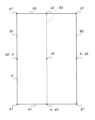
- FIG. 1 is a plane view conceptually showing a rectangular range used in a design method according to an embodiment of the present application.
- FIG. 13 is a plan view conceptually showing a method for determining a position for erecting a pillar in a design method according to one embodiment.
- FIG. 11 is a plan view showing a state in which a pillar has been written in a rectangular area in a design method according to one embodiment.
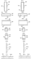
- FIG. 1 illustrates a column list, beam list, wall list, and slab list used in a design method according to one embodiment.
- 1 is a plan view conceptually showing a method for determining the placement positions of a frontage beam and a foundation frontage beam in a design method according to one embodiment.
- FIG. 1 is a plan view conceptually showing a method for determining the placement positions of a depth beam and a foundation depth beam in a design method according to one embodiment.
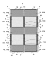
- FIG. FIG. 13 is a plan view conceptually showing a method for determining wall placement positions in a design method according to one embodiment.
- FIG. 13 is a plan view conceptually showing another method for determining wall placement positions in a design method according to one embodiment.
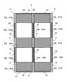
- FIG. 13 is a plan view conceptually showing a method for determining the placement position of a slab in a design method according to one embodiment.
- FIG. 10 is a diagram showing the reinforced concrete structure designed as shown in FIG. 9 as viewed from the side in FIG. 9 .
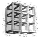
- FIG. 2 is a perspective view of an example of a frame of a reinforced concrete structure designed by a design method according to an embodiment.
- FIG. 11 is a perspective view of another example of a frame of a reinforced concrete structure designed by the design method according to one embodiment.
- design method for a reinforced concrete residential structure according to the present invention (hereinafter, simply referred to as the "design method") and the reinforced concrete residential structure designed by carrying out the design method.
- a reinforced concrete structure designed by this design method is designed based on a rectangular area ⁇ of a rectangle in a plan view as shown in FIG.
- the rectangular range ⁇ is a rectangular range in plan view defined by a frontage line segment A1 and a depth line segment B1 that are perpendicular to each other.
- the rectangular range ⁇ is a rectangle whose four sides are the frontage line segment A1, the depth line segment B1, the line segment A2, and the line segment B2.
- the frontage line segment A1 and the line segment A2 are opposite sides that are parallel to each other, and the depth line segment B1 and the line segment B2 are opposite sides that are parallel to each other.
- the frontage line segment A1, the line segment A2, the depth line segment B1, and the line segment B2 are all lines drawn on the ground on which the reinforced concrete structure is to be built.
- the frontage line segment A1 corresponds to one side of a reinforced concrete skeleton to be built later, which will be described later and will have a substantially rectangular parallelepiped shape, in a plan view
- the depth line segment B1 corresponds to the other side perpendicular to the frontage line segment A1 of the reinforced concrete skeleton.
- the frontage line segment A1 does not necessarily correspond to the frontage of the reinforced concrete skeleton to be built later, and the depth line segment B1 does not necessarily correspond to the depth of the reinforced concrete skeleton to be built later, but in this embodiment, the frontage line segment A1 corresponds to the frontage of the reinforced concrete skeleton to be built later, and the depth line segment B1 corresponds to the depth of the reinforced concrete skeleton to be built later.
- the frontage line segment A1 and the depth line segment B1 are appropriately determined according to the shape and size of the reinforced concrete skeleton to be built later, based on the shape and size of the site on which the reinforced concrete skeleton will be built. There may be cases where either the frontage line segment A1 or the depth line segment B1 is longer.
- the reinforced concrete structure constructed based on the above-mentioned rectangular range ⁇ includes a frame equipped with columns, front beams, front foundation beams, depth beams, and foundation depth beams. All of these are long materials, with the columns extending vertically, the front beams and front foundation beams extending horizontally in the front line direction, and the depth beams and foundation depth beams extending horizontally in the depth line direction.
- the position where the pillars are erected is determined by the following three rules, Rule 1 to Rule 3. Rules 1 to 3 will be explained with reference to Figs. 2 and 3. Rule 1)
- Rule 1 to 3 will be explained with reference to Figs. 2 and 3.
- Rule 1) The pillars P are erected at least on both ends of the two sides of the rectangular area ⁇ that are parallel to the depth line segment B1. In other words, the pillars are always erected at the four corners of the rectangular area ⁇ .
- the pillar P is erected at a depth division position b, which is a position on two sides that evenly divide the two sides parallel to the depth line segment B1 into lengths less than the first length.
- rule 3 When the frontage line segment A1 is longer than the second length, which is a predetermined length, pillars P are erected at both ends of auxiliary line segment B3, which is a virtual line segment of the same length as depth line segment B1 and extends parallel to depth line segment B1 from frontage division position a, which is a position on frontage line segment A1 that divides frontage line segment A1 evenly into lengths equal to or shorter than the second length, and at positions corresponding to depth division position b in the case that depth division position b exists on depth line segment B1.
- frontage division position a which is a position on frontage line segment A1 that divides frontage line segment A1 evenly into lengths equal to or shorter than the second length, and at positions corresponding to depth division position b in the case that depth division position b exists on depth line segment B1.
- rule 1 determines that pillars P are to be erected at four locations marked with p1.
- rule 2 the first length L1 appears (see FIG.
- the first length L1 is determined in advance when determining a reference frame, which will be described later.
- the first length L1 is determined in advance within a range of, for example, 4500 mm to 5700 mm. Although not limited to this, in this embodiment, the first length L1 is set to 5100 mm.
- the pillar P cannot be erected on the depth line segment B1 at any position other than p1 on both ends thereof, and the pillar P cannot be erected on the line segment B2 at any position other than p1 on both ends thereof.
- the length l1 of the depth line segment B1 is longer than the first length L1
- a pillar P is erected on the depth line segment B1 at the depth division position b in addition to the pillars p1 at both ends of the depth line segment B1.
- the depth division position b is a position at which the depth line segment B1 is divided when the depth line segment B1 is divided evenly by natural numbers as small as possible.
- the center of the depth line segment B1 becomes the depth division position b.
- the two positions that divide the depth line segment B1 into three equal parts become the depth division positions b.
- the n positions on the depth line segment B1 that divides the depth line segment B1 into n+1 equal parts become depth division positions b.
- the depth division position b is one location at the center of the depth line segment B1.
- the pillar P is erected at two locations: the center p2 of the depth line segment B1 and the center p2 of the line segment B2 parallel to the depth line segment B1.
- rule 3 the second length L2 appears (see FIG. 1).
- the second length L2 is determined in advance when determining the reference frame described later.
- the second length L2 can be determined in advance, for example, in the range of 3700 mm to 5100 mm. Although not limited to this, in this embodiment, the second length L2 is set to 4100 mm.
- the second length L2 can be different lengths depending on whether the reinforced concrete structure to be designed is for a detached house or for an apartment building.
- the second length L2 can be set to an appropriate length in the range of 4700 mm to 5100 mm (for example, 4900 mm), and when it is for an apartment building, the second length L2 can be set to an appropriate length in the range of 3700 mm to 4100 mm (for example, 3900 mm).
- the frontage division position a which is the position on the frontage line segment A1 that divides the frontage line segment A1 into equal parts of length equal to or less than the second length L2, is first obtained.
- the n positions on the frontage line segment A1 that divide the frontage line segment A1 into n+1 equal parts are the frontage division positions a.
- an auxiliary line segment B3 is obtained from there, which has a length equal to the depth line segment B1 and extends parallel to the depth line segment B1.
- the auxiliary line segment B3 is a line segment that connects the frontage line segment A1 and the line segment A2 so as to be perpendicular to both of them.
- the number of the auxiliary line segments B3 is n.
- the pillars P are erected at both ends p3 of the auxiliary line segment B3 and at a position p3 on the auxiliary line segment B3 that corresponds to the depth division position b.
- there is one frontage division position a and one auxiliary line segment B3 and the pillars P are erected at both ends p3 of the auxiliary line segment B3 and at the center p3 of the auxiliary line segment B3.
- FIG. 3 shows a case where it has been decided to erect pillars P at positions p1, p2, and p3 in the rectangular area ⁇ .
- the pillar P is rectangular in plan view, with the length in the depth direction (direction along the depth line segment B1) being longer than the length in the frontage direction (direction along the frontage line segment A1).
- the pillar P in this embodiment has a rectangular cross section with a length in the frontage direction of 400 mm and a length in the depth direction of 1200 mm.
- the numbers mentioned above for the first length L1 and the second length L2 are examples in which the cross-sectional shape of the pillar P is 400 mm x 1200 mm.
- Each column P has the same thickness and the same configuration of reinforcing bars in the longitudinal direction.
- the thickness or cross-sectional shape of each column P is the same in all parts in the longitudinal direction that are equal to or less than the third length, and the reinforcing bars arranged in the column P run inside the column P in the longitudinal direction.
- the third length can be determined, for example, as the upper limit assumed as the floor height per floor. That is, although all columns P in the reinforced concrete skeleton are limited to have a length equal to or less than the third length, the length does not need to be uniquely determined in advance.
- the configuration excluding the length of the column P in other words, the configuration per unit length, is standardized in a uniform manner.
- the length of the column P determines the floor height of the floor to which the column P belongs in the reinforced concrete skeleton
- the lengths of all columns P belonging to the same floor are made equal.
- the floor height of each floor of the reinforced concrete skeleton, which is a multi-story structure with multiple floors is the same.
- all columns P belonging to each floor of the reinforced concrete skeleton adopting a multi-story structure are assumed to have the same length.
- Fig. 4 (A-1) and (B-1) Examples of a column list showing the configuration of a column P used in a reinforced concrete skeleton are shown in Fig. 4 (A-1) and (B-1).
- Fig. 4 (A-1) shows a column list when the reinforced concrete skeleton is for a detached house
- Fig. 4 (B-1) shows a column list when the reinforced concrete skeleton is for an apartment building. All of the columns in the column list are cross-sectional views of the column P.
- 191 is a long reinforcing bar that runs in the length direction of the column P or in a direction perpendicular to the paper
- 192 is a loop-shaped reinforcing bar that surrounds the long reinforcing bar 191 to prevent the position from shifting.
- the dimensions of the column P excluding the length, and the configuration of the reinforcing bar (the arrangement position of the long reinforcing bar 191 including the number, the interval in the length direction of the reinforcing bar 191 where the loop-shaped reinforcing bar 192 is arranged, the type of the reinforcing bar 191, 192, etc.) are generally recorded. It is also possible to standardize the column list for detached houses and apartment buildings. While a large number of column lists are created for columns used in a typical concrete structure, rather than multiple, the number of column lists in this embodiment is small.
- the positions at which the frontage beams and foundation frontage beams are to be disposed are determined by the following two rules, Rule 4 to Rule 5. Rules 4 to 5 will be described with reference to FIG. Rule 4)
- the frontage beam FB is arranged so as to horizontally connect the upper and lower ends of all two columns P that are parallel to and adjacent to the frontage line segment A1, in a direction parallel to the frontage line segment A1.
- the foundation frontage beam FFB is positioned so as to horizontally connect the lower ends of all two columns P that are parallel to and adjacent to the frontage line segment A1, and that are in contact with the ground, in a direction parallel to the frontage line segment A1.
- a frontage beam FB or a foundation frontage beam FFB is stretched between two columns P arranged side by side in Fig. 5.
- Fig. 5 is a plan view, and the frontage beam FB and the foundation frontage beam FFB overlap each other. Both the frontage beam FB and the foundation frontage beam FFB are long.
- both the frontage beam FB and the foundation frontage beam FFB which is a type of frontage beam FB, have a rectangular cross section, and their width, which is their length in the depth direction, is set equal to the length in the depth direction of the column P.
- Both the frontage beam FB and the foundation frontage beam FFB are connected to the column P so that both ends in the width direction are aligned with both ends in the depth direction of the column P.
- Each front beam FB has the same thickness and the same configuration of the reinforcing bars in the longitudinal direction, as does the foundation front beam FFB.
- the front beam FB and the foundation front beam FFB have the same thickness or cross-sectional shape in all parts in the longitudinal direction, and the reinforcing bars arranged in the front beam FB or the foundation front beam FFB run inside them in the longitudinal direction.
- the length of all the frontage beams FB or foundation frontage beams FFB in the reinforced concrete structure must be equal to or less than the second length L2, the length does not need to be uniquely determined in advance.
- the configuration excluding the length of the frontage beams FB or foundation frontage beams FFB in other words, the configuration per unit length, is standardized in a uniform manner. Note that the length of multiple frontage beams FB that exist in one reinforced concrete structure is the same.
- the length of multiple foundation frontage beams FFB that exist is the same. Furthermore, the lengths of the frontage beams FB and the foundation frontage beams FFB are also the same. Examples of beam lists showing the configuration of the front beam FB used in a reinforced concrete structure are shown in Figures 4 (A-2), (A-3), (B-2), and (B-3).
- Figure 4 (A-2) shows a beam list of the front beam FB when the reinforced concrete structure is for a detached house
- (B-2) shows a beam list of the front beam FB when the reinforced concrete structure is for an apartment building.
- FIG. 4 shows a beam list of the foundation front beam FFB when the reinforced concrete structure is for a detached house
- (B-3) shows a beam list of the foundation front beam FFB when the reinforced concrete structure is for an apartment building.
- the above beam list shows a cross-sectional view of the frontage beam FB or foundation frontage beam FFB.
- 191 is a reinforcing bar running in the length direction of the frontage beam FB or foundation frontage beam FFB or in a direction perpendicular to the paper
- 192 is a loop-shaped reinforcing bar that surrounds the long reinforcing bar 191 to prevent their position from shifting.
- the dimensions of the frontage beam FB or foundation frontage beam FFB excluding the length, the configuration of the reinforcing bar (the arrangement position of the long reinforcing bar 191 including the number, the interval in the length direction of the reinforcing bar 191 where the loop-shaped reinforcing bar 192 is arranged, the type of the reinforcing bar 191, 192, etc.) are generally recorded. It is also possible to make the beam list for the frontage beam FB and foundation frontage beam FFB common to both detached houses and apartment buildings. Since the foundation front beam FFB is generally required to be stronger than the front beam FB, the thickness (or height) of the latter is made greater than the thickness of the former, regardless of whether it is for a detached house or an apartment building.
- a large number of beam lists are created for the frontage beams FB or foundation frontage beams FFB used in the structure, rather than multiple lists. In this embodiment, however, the number of beam lists for the frontage beams FB or foundation frontage beams FFB is small.
- the positions at which the depth beams and the foundation depth beams are disposed are determined by the following two rules, Rule 6 to Rule 7. Rules 6 to 7 will be described with reference to FIG. Rule 6)
- the depth beam DB is arranged so as to horizontally connect the upper and lower ends of all two columns P that are parallel to and adjacent to the depth line segment B1, in a direction parallel to the depth line segment B1.
- the foundation depth beam FDB is arranged so as to horizontally connect the lower ends of all two columns P that are parallel to and adjacent to the depth line B1, and that are in contact with the ground, in a direction parallel to the depth line B1. Please refer to Figure 6.
- a depth beam DB or a foundation depth beam FDB is stretched between two columns P located above and below in Fig. 6.
- Fig. 6 is a plan view, and the depth beam DB and the foundation depth beam FDB overlap each other.
- the depth beam DB and the foundation depth beam FDB are both long. However, their lengths are equal to or shorter than the first length L1, and are automatically determined by the positional relationship of the two columns P that are connected by them.
- the depth beam DB and the foundation depth beam FDB which is a type of depth beam DB, both have a rectangular cross section, and their width, which is the length in the frontage direction, is set equal to the length in the frontage direction of the column P.
- the depth beam DB and the foundation depth beam FDB are both connected to the column P so that both ends in the width direction are aligned with both ends in the frontage direction of the column P.
- Each depth beam DB has the same thickness and longitudinal rebar configuration, as does the foundation depth beam FDB.
- the thickness or cross-sectional shape of both the depth beam DB and the foundation depth beam FDB is the same throughout their length, and the rebars arranged within the depth beam DB or the foundation depth beam FDB run along their length. In other words, although there is a restriction that the length of all the depth beams DB or foundation depth beams FDB in a reinforced concrete structure must be equal to or less than the first length L1, the length does not need to be uniquely determined in advance.
- the configuration excluding the length of the depth beam DB or foundation depth beam FDB in other words, the configuration per unit length, is standardized in a uniform manner.
- the length of multiple depth beams DB that exist in one reinforced concrete structure is the same.
- the length of multiple foundation depth beams FDB that exist is the same.
- the lengths of the depth beams DB and foundation depth beams FDB are also the same. Examples of beam lists showing the configuration of the depth beam DB used for a reinforced concrete skeleton are shown in Figures 4 (A-4), (A-5), (B-4), and (B-5).
- Figure 4 (A-4) shows the beam list of the depth beam DB when the reinforced concrete skeleton is for a detached house
- Figure 4 (B-4) shows the beam list of the depth beam DB when the reinforced concrete skeleton is for an apartment building
- Figure 4 (A-5) shows the beam list of the foundation depth beam FDB when the reinforced concrete skeleton is for a detached house
- Figure 4 (B-5) shows the beam list of the foundation depth beam FDB when the reinforced concrete skeleton is for an apartment building.
- the above beam list shows a cross section of the depth beam DB or foundation depth beam FDB.
- 191 is a reinforcing bar running in the length direction of the depth beam DB or foundation depth beam FDB or in a direction perpendicular to the paper
- 192 is a loop-shaped reinforcing bar that surrounds the long reinforcing bar 191 to prevent their position from shifting.
- the dimensions of the depth beam DB or foundation depth beam FDB excluding the length, the configuration of the reinforcing bar (the arrangement position of the long reinforcing bar 191 including the number, the interval in the length direction of the reinforcing bar 191 where the loop-shaped reinforcing bar 192 is arranged, the type of the reinforcing bar 191, 192, etc.) are generally recorded.
- the beam list for the depth beam DB and the foundation depth beam FDB can be made common to both detached houses and apartment buildings. Since the foundation depth beam FDB generally requires greater strength than the depth beam DB, the latter is made thicker (or taller) than the former, regardless of whether it is for a detached house or an apartment building. In this embodiment, although not limited thereto, the thickness of the frontage beam FB and the depth beam DB are made the same, and the thickness of the foundation frontage beam FFB and the foundation depth beam FDB are made the same.
- a large number of beam lists for the depth beam DB or foundation depth beam FDB used in a typical concrete structure are created rather than multiple, but in this embodiment the number of beam lists for the depth beam DB or foundation depth beam FDB is small.
- the wall W fills the gap between adjacent columns P located on two sides parallel to the depth line segment B1 of the rectangular area ⁇ or on the auxiliary line segment B3.
- the walls W are rectangular.
- the walls W arranged according to rule 8 have four vertical sides connected to the columns P and two horizontal sides connected to the frontage beam FB or the foundation frontage beam FFB.
- the walls W are basically constructed on the frontage line segment A1 in the rectangular range ⁇ and the line segment A2 opposite the frontage line segment A1 (that is, on the contour of the rectangular range ⁇ ).
- the wall W may be arranged at a position that is inward from the frontage line segment A1 into the rectangular range ⁇ , as in the lower wall W in FIG. 8.
- the walls W may be designed to be arranged at a position away from the contour of the rectangular range ⁇ .
- six walls are arranged with their length direction being the vertical direction in Fig. 7 and Fig. 8.
- the walls W are rectangular.
- the walls W arranged according to rule 9 have four sides, two vertical sides connected to the columns P, and two horizontal sides connected to the depth beam DB or the foundation depth beam FDB. Even in this case, the walls W that are not on the auxiliary line segment B3 are allowed to be positioned outside the contour of the rectangular area ⁇ (i.e., a certain degree of freedom is given to the position of the walls W). However, in Fig. 7 and Fig. 8, the walls W are arranged on the contour of the rectangular area ⁇ , that is, on the depth line segment B1 and the line segment B2 that is the opposite side of the depth line segment B1. Whether the walls W are arranged according to rule 8 or 9, they are always plate-shaped, as is well known.
- the walls W are also standardized like the columns P, etc., so that they have the same structure per unit area.
- the walls W do not bear the role of supporting the weight of the reinforced concrete structure, so their robustness need only be at a minimum.
- Examples of wall lists showing the configuration of walls W used in a reinforced concrete skeleton are shown in Figures 4 (A-6) and (B-6).
- Figure 4 (A-6) shows a wall list of walls W when the reinforced concrete skeleton is for a single-family home
- Figure 4 (B-6) shows a wall list of walls W when the reinforced concrete skeleton is for an apartment building. All of the above wall lists are cross-sectional views of a wall W.
- 191 denotes reinforcing bars running in the wall W in the width direction or in the direction perpendicular to the paper surface.
- 191X denotes reinforcing bars running in the wall W parallel to the paper surface in the vertical direction relative to the paper surface.
- the wall list the dimensions of the wall (wall thickness) and the composition of the reinforcing bars (the spacing between reinforcing bars 191, 191X running in the width direction and height direction of the wall W, the type of reinforcing bars, etc.) are generally recorded. It is also possible to have a common wall list for walls W for detached houses and for apartment buildings.
- the position where the slab is placed is determined by the following rule 10.
- Rule 10 will be described with reference to Figs. Rule 10)
- the slab S horizontally fills a rectangular space surrounded by two front beams FB and two depth beams DB, or two foundation front beams FFB and two foundation depth beams FDB, at the height above and below the column P.
- Figure 10 is a diagram showing the reinforced concrete skeleton designed as shown in Figure 9, as viewed from the side in Figure 9. However, in Figure 10, the wall W is omitted.
- four slabs S are arranged in a 2x2 grid in Fig. 9.
- the slabs S are rectangular.
- the slabs S arranged according to rule 10 are horizontal and arranged above and below the columns P.
- the four sides of the slab S are connected to two front beams FB and two depth beams DB, or two foundation front beams FFB and two foundation depth beams FDB.
- all slabs S are plate-shaped.
- Slabs S are also standardized like columns P, etc., so that they have the same configuration per unit area. Since slabs S do not play a role in supporting the weight of the reinforced concrete structure, their robustness is only required to be at a minimum. Examples of slab lists showing the configuration of slabs S used in reinforced concrete structures are shown in Figures 4 (A-7) and (B-7).
- Figure 4 (A-7) shows a slab list for slabs S when the reinforced concrete structure is for a single-family home
- Figure 4 (B-7) shows a slab list for slabs S when the reinforced concrete structure is for an apartment building.
- All of the above slab lists are cross-sectional views of slab S.
- 191 denotes reinforcing bars that run through slab S in a direction perpendicular to the paper.
- 191X denotes reinforcing bars that run through slab S in a left-right direction parallel to the paper.
- Slab lists generally record the dimensions of the slab (slab thickness) and the configuration of reinforcing bars (the spacing and type of reinforcing bars 191, 191X that run perpendicular to each other through slab S, etc.). It is also possible to standardize slab lists for slabs S for single-family homes and apartment buildings.
- the top ends of the newly added columns P are connected with the front beams FB and depth beams DB, and the walls W and slabs S are placed.
- the walls W and slabs S are placed.
- the design of the reinforced concrete skeleton for a house is completed.
- the design order of the column P, frontage beam FB, foundation frontage beam FFB, depth beam DB, foundation depth beam FDB, wall W, and slab S does not have to be the order described above.
- it is not necessary to design the first floor before designing the second floor for example, the entire frame of a multi-story reinforced concrete structure may be designed first, and then the walls W and slabs S to be attached to the frame may be designed.
- the design of the holes for mounting the window frames and the holes for mounting the doors to be made in the wall W is omitted, and the design of the holes to be made in the slab S required to provide an internal staircase is omitted, but these can be designed in accordance with conventional technology.
- this reinforced concrete structure for example, it is possible to make one side of any of the walls W entirely made of glass. Even in this case, the walls W and slabs S do not bear the role of supporting the load of the reinforced concrete structure, so sufficient strength of the reinforced concrete structure is guaranteed.
- FIG. 11 and FIG. 11 and 12 are perspective views of a frame F in a reinforced concrete structure designed by the design method for a reinforced concrete structure described above.
- FIG. 11 of the two sides on the front side of the rectangular area ⁇ at the bottom edge of the frame F, the left side is a frontage line segment A1 and the right side is a depth line segment B1.
- the frontage line segment A1 is equal to or shorter than the second length L2, and the depth line segment B1 is more than twice the first length L1 and less than three times the first length L1.
- the frame F designed according to the above-mentioned rules 1 to 7 is as shown in Fig. 11.
- the rectangular parallelepiped area defined by the four columns P, four frontage beams FB (more precisely, two frontage beams FB and two foundation frontage beams FFB), and four depth beams DB (more precisely, two depth beams DB and two foundation depth beams FDB) shown in the shaded area in the figure corresponds to the reference frame SF explained in the overview of the present invention.
- the frame F shown in Fig. 11 is a combination of one reference frame SF in the frontage line segment A1 direction, three in the depth line segment B direction, and three in the vertical direction.
- FIG. 11 is a combination of one reference frame SF in the frontage line segment A1 direction, three in the depth line segment B direction, and three in the vertical direction.
- the right side is a frontage line segment A1 and the left side is a depth line segment B1.
- the frontage line segment A1 is longer than twice the second length L2 but shorter than three times the second length L2, and the depth line segment B1 is equal to or shorter than the first length L1.
- the frame F designed according to the above-mentioned rules 1 to 7 is as shown in Fig. 12.
- the frame shown in Fig. 12 is formed by lining up three reference frames SF explained in Fig. 11 in the direction of the frontage line segment A1, one in the direction of the depth line segment B, and three in the vertical direction.
- the columns P, frontage beams FB, foundation frontage beams FFB, depth beams DB, foundation depth beams FDB, walls W, and slabs S are connected together in X, Y, and Z numbers of reference frames SF in the frontage line direction, depth line direction, and vertical direction, respectively, to form a frame F having a generally rectangular parallelepiped shape as a whole (however, restrictions can be placed on the combinations of X, Y, and Z). Furthermore, even if walls W and slabs S are added to the frame F in accordance with rules 8 to 10 described above, the frame F is standardized so that it is sufficient to support the load of the entire reinforced concrete structure.
- the reinforced concrete structure having the frame F created by arranging the reference frame SF in the length, width, and height directions is guaranteed to have sufficient strength to support the load of the reinforced concrete structure.
- the above-mentioned column list specifying the configuration of the column P the above-mentioned beam list specifying the configuration of the front beam FB, the foundation front beam FFB, the depth beam DB, and the foundation depth beam FDB, the above-mentioned wall list specifying the configuration of the wall W, and the above-mentioned slab list specifying the configuration of the slab S are prepared in advance as a set in a state that satisfies the condition that the frame F is sufficient to support the load of the reinforced concrete structure when the reference frame SF is arranged in the length, width, and height directions, the frame F in the reinforced concrete structure created according to the above-mentioned rules 1 to 10 will automatically have sufficient strength to support the load of the reinforced concrete structure.
- the frame F in the reinforced concrete structure designed in this manner will have an approximately rectangular parallelepiped shape in which reference frames SF are stacked in the length, width, and height directions, or in which frames (quasi-reference frames described in the overview of the present invention) that are shorter than the reference frame SF in at least one of the length, width, and height directions are stacked in the length, width, and height directions.
- the reinforced concrete structure having the frame F shown in Figure 11 is suitable for a detached house equipped with an internal staircase connecting the first and second floors and an internal staircase connecting the second and third floors.
- two auxiliary line segments B3 are used.
- walls W are arranged on each of the first to third floors so as to divide each floor into three. Therefore, by providing an internal staircase connecting the first and second floors and an internal staircase connecting the second and third floors, the reinforced concrete structure having the frame F shown in Fig.
- the reinforced concrete structure having the frame shown in Fig. 12 can be suitable for an apartment building with a total of nine rooms, with three independent rooms on each floor.
- the reinforced concrete structure in this embodiment is constructed according to the design drawings designed by the design method described above.
- the reinforced concrete structure can be constructed using conventional construction methods. For example, in the case of a reinforced concrete structure for a one-story house, first the formwork is assembled and rebar is appropriately placed inside the formwork, and concrete is then poured into the assembled formwork and allowed to harden while curing, thereby constructing the foundation front beam FFB, foundation depth beam FDB, and slab S, which corresponds to the first floor floor. Next, the formwork assembled to construct the foundation front beam FFB and the foundation depth beam FDB is removed, and then the formwork is assembled again with appropriate rebar placed inside the formwork.
- Concrete is poured into the assembled formwork and cured while being hardened, thereby constructing the columns P, front beam FB, depth beam DB, walls W, and a slab S equivalent to the ceiling of the first floor.
- the formwork assembled to construct the columns P, front beams FB, depth beams DB, walls W, and slab S corresponding to the first floor ceiling of the first floor is removed, and then the formwork is assembled again and rebar is placed inside the formwork as appropriate.
- the reinforcing bars extending in the length direction of the column P, the reinforcing bars extending in the length direction of the frontage beam FB, and the reinforcing bars extending in the length direction of the depth beam DB, or the reinforcing bars extending in the length direction of the column P, the reinforcing bars extending in the length direction of the foundation frontage beam FFB, and the reinforcing bars extending in the length direction of the foundation depth beam FDB, are each made to intersect.
- the connections between the column P and the frontage beam FB, the column P and the depth beam DB, the column P and the foundation frontage beam FFB, and the column P and the foundation depth beam FDB can be strengthened, which helps to increase the resistance to load of the reinforced concrete structure.
- the long reinforcing bars 191 in the column P usually extend from the top to the bottom of the reinforced concrete skeleton.
- the ends of the reinforcing bars extending in the length direction of the frontage beam FB, the reinforcing bars extending in the length direction of the depth beam DB, the reinforcing bars extending in the length direction of the foundation frontage beam FFB, and the reinforcing bars extending in the length direction of the foundation depth beam FDB can all be inserted into the column P by an appropriate length, for example, about 400 mm.
- the portions of the reinforcing bars extending in the length direction of the frontage beam FB, the reinforcing bars extending in the length direction of the depth beam DB, the reinforcing bars extending in the length direction of the foundation frontage beam FFB, and the foundation depth beam FDB that enter the column P may be bent at right angles or folded back in a U-shape.
- each reinforcing bar is fixed at the parts where the reinforcing bars extending in the length direction of column P, the reinforcing bars extending in the length direction of front beam FB, and the reinforcing bars extending in the length direction of depth beam DB, or where the reinforcing bars extending in the length direction of column P, the reinforcing bars extending in the length direction of foundation front beam FFB, and the reinforcing bars extending in the length direction of foundation depth beam FDB, intersect.
Landscapes
- Engineering & Computer Science (AREA)
- Architecture (AREA)
- Physics & Mathematics (AREA)
- Electromagnetism (AREA)
- Civil Engineering (AREA)
- Structural Engineering (AREA)
- Foundations (AREA)
- Joining Of Building Structures In Genera (AREA)
Abstract
Priority Applications (3)
| Application Number | Priority Date | Filing Date | Title |
|---|---|---|---|
| PCT/JP2023/030200 WO2025041278A1 (fr) | 2023-08-22 | 2023-08-22 | Squelette en béton renforcé pour maison, et procédé de conception d'un squelette en béton renforcé pour maison |
| JP2023562255A JP7384370B1 (ja) | 2023-08-22 | 2023-08-22 | 住宅用の鉄筋コンクリート製躯体、住宅用の鉄筋コンクリート製躯体の設計方法 |
| TW113130286A TW202516088A (zh) | 2023-08-22 | 2024-08-13 | 房屋用鋼筋混凝土製結構、房屋用鋼筋混凝土製結構之設計方法 |
Applications Claiming Priority (1)
| Application Number | Priority Date | Filing Date | Title |
|---|---|---|---|
| PCT/JP2023/030200 WO2025041278A1 (fr) | 2023-08-22 | 2023-08-22 | Squelette en béton renforcé pour maison, et procédé de conception d'un squelette en béton renforcé pour maison |
Publications (1)
| Publication Number | Publication Date |
|---|---|
| WO2025041278A1 true WO2025041278A1 (fr) | 2025-02-27 |
Family
ID=88833348
Family Applications (1)
| Application Number | Title | Priority Date | Filing Date |
|---|---|---|---|
| PCT/JP2023/030200 Pending WO2025041278A1 (fr) | 2023-08-22 | 2023-08-22 | Squelette en béton renforcé pour maison, et procédé de conception d'un squelette en béton renforcé pour maison |
Country Status (3)
| Country | Link |
|---|---|
| JP (1) | JP7384370B1 (fr) |
| TW (1) | TW202516088A (fr) |
| WO (1) | WO2025041278A1 (fr) |
Citations (4)
| Publication number | Priority date | Publication date | Assignee | Title |
|---|---|---|---|---|
| JPS5816410B2 (ja) * | 1979-07-09 | 1983-03-31 | 株式会社 鴻池組 | L型および一型プレキヤストコンクリ−ト造独立耐力壁による建家構法 |
| JPH0941669A (ja) * | 1995-07-28 | 1997-02-10 | Hazama Gumi Ltd | コンクリート構造物の施工構造及び流動状コンクリートの圧送方法 |
| JP2000257169A (ja) * | 1999-03-04 | 2000-09-19 | Sekisui Chem Co Ltd | 傾斜地におけるユニット建物構造 |
| JP2008217631A (ja) * | 2007-03-07 | 2008-09-18 | Sekisui Chem Co Ltd | 建物の構造設計支援システム |
-
2023
- 2023-08-22 WO PCT/JP2023/030200 patent/WO2025041278A1/fr active Pending
- 2023-08-22 JP JP2023562255A patent/JP7384370B1/ja active Active
-
2024
- 2024-08-13 TW TW113130286A patent/TW202516088A/zh unknown
Patent Citations (4)
| Publication number | Priority date | Publication date | Assignee | Title |
|---|---|---|---|---|
| JPS5816410B2 (ja) * | 1979-07-09 | 1983-03-31 | 株式会社 鴻池組 | L型および一型プレキヤストコンクリ−ト造独立耐力壁による建家構法 |
| JPH0941669A (ja) * | 1995-07-28 | 1997-02-10 | Hazama Gumi Ltd | コンクリート構造物の施工構造及び流動状コンクリートの圧送方法 |
| JP2000257169A (ja) * | 1999-03-04 | 2000-09-19 | Sekisui Chem Co Ltd | 傾斜地におけるユニット建物構造 |
| JP2008217631A (ja) * | 2007-03-07 | 2008-09-18 | Sekisui Chem Co Ltd | 建物の構造設計支援システム |
Also Published As
| Publication number | Publication date |
|---|---|
| JPWO2025041278A1 (fr) | 2025-02-27 |
| TW202516088A (zh) | 2025-04-16 |
| JP7384370B1 (ja) | 2023-11-21 |
Similar Documents
| Publication | Publication Date | Title |
|---|---|---|
| ES2796730T3 (es) | Método para la construcción de edificios de varios pisos utilizando soportes de pared de acero estructural apilados | |
| KR101389203B1 (ko) | 프리캐스트 콘크리트 골조와 모듈러 유닛을 이용한 중고층 주거용 건축물의 시공방법 | |
| CN210529949U (zh) | 一种装配式建筑 | |
| CN111155651A (zh) | 一种装配式建筑及其装配方法 | |
| CN1821501B (zh) | 建筑物的柱梁连接构造体及其连接方法 | |
| JP7411749B2 (ja) | コンクリート造建物の構築方法 | |
| KR100855547B1 (ko) | 클린룸 건축물의 골조 연결 구조 | |
| KR101590794B1 (ko) | 콘크리트 충전형 기둥과 연결마구리판을 이용한 유닛구조체 및 그 시공방법 | |
| KR20010012535A (ko) | 건물 골격구조물 | |
| WO2025041278A1 (fr) | Squelette en béton renforcé pour maison, et procédé de conception d'un squelette en béton renforcé pour maison | |
| KR101464073B1 (ko) | 거푸집 없이 시공되는 패널 일체형 콘크리트 벽체 및 이를 포함하는 건축 구조물 | |
| KR102567389B1 (ko) | 다단형 계단실 구조체 및 그 시공방법 | |
| JP5637357B2 (ja) | 既存鉄筋コンクリート集合住宅の耐震補強構造 | |
| KR101290217B1 (ko) | 단위세대 맞통풍 구조의 y형 건물 | |
| CA1081495A (fr) | Procede de construction de batiments d'habitation ou industriels | |
| CN115142553B (zh) | 多层装配式混凝土板式结构房屋及其安装方法 | |
| JP3707378B2 (ja) | Pc部材を用いた建築構造 | |
| JP2006037649A (ja) | 集合住宅の架構構造 | |
| CN114960961A (zh) | 单层装配式混凝土板式结构房屋及其安装方法 | |
| JP2634744B2 (ja) | ユニット式建物 | |
| JP6994824B2 (ja) | 構造物の構築方法 | |
| KR20220016568A (ko) | 일체형 룸-조립체 및 벽체를 이용한 건축구조물 시공 방법 | |
| CN204531070U (zh) | 一种内包混凝土柱、圈梁的自保温组合夹心填充墙 | |
| JP3528874B2 (ja) | 集合住宅 | |
| CN211873517U (zh) | 一种模板、模板组件及装配式模板模块 |
Legal Events
| Date | Code | Title | Description |
|---|---|---|---|
| ENP | Entry into the national phase |
Ref document number: 2023562255 Country of ref document: JP Kind code of ref document: A |
|
| WWE | Wipo information: entry into national phase |
Ref document number: 2023562255 Country of ref document: JP |
|
| 121 | Ep: the epo has been informed by wipo that ep was designated in this application |
Ref document number: 23949739 Country of ref document: EP Kind code of ref document: A1 |
|
| WWE | Wipo information: entry into national phase |
Ref document number: 202517036352 Country of ref document: IN |
|
| WWE | Wipo information: entry into national phase |
Ref document number: 2501002740 Country of ref document: TH |
|
| WWP | Wipo information: published in national office |
Ref document number: 202517036352 Country of ref document: IN |
|
| NENP | Non-entry into the national phase |
Ref country code: DE |