WO2025046708A1 - 工作機械、工作機械システム、プログラム、工作機械の制御方法、及び、プログラムの生成方法 - Google Patents
工作機械、工作機械システム、プログラム、工作機械の制御方法、及び、プログラムの生成方法 Download PDFInfo
- Publication number
- WO2025046708A1 WO2025046708A1 PCT/JP2023/031014 JP2023031014W WO2025046708A1 WO 2025046708 A1 WO2025046708 A1 WO 2025046708A1 JP 2023031014 W JP2023031014 W JP 2023031014W WO 2025046708 A1 WO2025046708 A1 WO 2025046708A1
- Authority
- WO
- WIPO (PCT)
- Prior art keywords
- machine tool
- information
- program
- control
- tool
- Prior art date
- Legal status (The legal status is an assumption and is not a legal conclusion. Google has not performed a legal analysis and makes no representation as to the accuracy of the status listed.)
- Pending
Links
Images



Classifications
-
- G—PHYSICS
- G05—CONTROLLING; REGULATING
- G05B—CONTROL OR REGULATING SYSTEMS IN GENERAL; FUNCTIONAL ELEMENTS OF SUCH SYSTEMS; MONITORING OR TESTING ARRANGEMENTS FOR SUCH SYSTEMS OR ELEMENTS
- G05B19/00—Program-control systems
- G05B19/02—Program-control systems electric
- G05B19/18—Numerical control [NC], i.e. automatically operating machines, in particular machine tools, e.g. in a manufacturing environment, so as to execute positioning, movement or co-ordinated operations by means of program data in numerical form
- G05B19/4093—Numerical control [NC], i.e. automatically operating machines, in particular machine tools, e.g. in a manufacturing environment, so as to execute positioning, movement or co-ordinated operations by means of program data in numerical form characterised by part programming, e.g. entry of geometrical information as taken from a technical drawing, combining this with machining and material information to obtain control information, named part program, for the NC machine
- G05B19/40937—Numerical control [NC], i.e. automatically operating machines, in particular machine tools, e.g. in a manufacturing environment, so as to execute positioning, movement or co-ordinated operations by means of program data in numerical form characterised by part programming, e.g. entry of geometrical information as taken from a technical drawing, combining this with machining and material information to obtain control information, named part program, for the NC machine concerning programming of machining or material parameters, pocket machining
- G05B19/40938—Tool management
-
- G—PHYSICS
- G05—CONTROLLING; REGULATING
- G05B—CONTROL OR REGULATING SYSTEMS IN GENERAL; FUNCTIONAL ELEMENTS OF SUCH SYSTEMS; MONITORING OR TESTING ARRANGEMENTS FOR SUCH SYSTEMS OR ELEMENTS
- G05B19/00—Program-control systems
- G05B19/02—Program-control systems electric
- G05B19/18—Numerical control [NC], i.e. automatically operating machines, in particular machine tools, e.g. in a manufacturing environment, so as to execute positioning, movement or co-ordinated operations by means of program data in numerical form
- G05B19/4097—Numerical control [NC], i.e. automatically operating machines, in particular machine tools, e.g. in a manufacturing environment, so as to execute positioning, movement or co-ordinated operations by means of program data in numerical form characterised by using design data to control NC machines, e.g. CAD/CAM
-
- G—PHYSICS
- G05—CONTROLLING; REGULATING
- G05B—CONTROL OR REGULATING SYSTEMS IN GENERAL; FUNCTIONAL ELEMENTS OF SUCH SYSTEMS; MONITORING OR TESTING ARRANGEMENTS FOR SUCH SYSTEMS OR ELEMENTS
- G05B19/00—Program-control systems
- G05B19/02—Program-control systems electric
- G05B19/18—Numerical control [NC], i.e. automatically operating machines, in particular machine tools, e.g. in a manufacturing environment, so as to execute positioning, movement or co-ordinated operations by means of program data in numerical form
-
- G—PHYSICS
- G05—CONTROLLING; REGULATING
- G05B—CONTROL OR REGULATING SYSTEMS IN GENERAL; FUNCTIONAL ELEMENTS OF SUCH SYSTEMS; MONITORING OR TESTING ARRANGEMENTS FOR SUCH SYSTEMS OR ELEMENTS
- G05B19/00—Program-control systems
- G05B19/02—Program-control systems electric
- G05B19/18—Numerical control [NC], i.e. automatically operating machines, in particular machine tools, e.g. in a manufacturing environment, so as to execute positioning, movement or co-ordinated operations by means of program data in numerical form
- G05B19/188—Numerical control [NC], i.e. automatically operating machines, in particular machine tools, e.g. in a manufacturing environment, so as to execute positioning, movement or co-ordinated operations by means of program data in numerical form characterised by special applications and not provided for in the relevant subclasses, (e.g. making dies, filament winding)
-
- G—PHYSICS
- G05—CONTROLLING; REGULATING
- G05B—CONTROL OR REGULATING SYSTEMS IN GENERAL; FUNCTIONAL ELEMENTS OF SUCH SYSTEMS; MONITORING OR TESTING ARRANGEMENTS FOR SUCH SYSTEMS OR ELEMENTS
- G05B19/00—Program-control systems
- G05B19/02—Program-control systems electric
- G05B19/18—Numerical control [NC], i.e. automatically operating machines, in particular machine tools, e.g. in a manufacturing environment, so as to execute positioning, movement or co-ordinated operations by means of program data in numerical form
- G05B19/408—Numerical control [NC], i.e. automatically operating machines, in particular machine tools, e.g. in a manufacturing environment, so as to execute positioning, movement or co-ordinated operations by means of program data in numerical form characterised by data handling or data format, e.g. reading, buffering or conversion of data
- G05B19/4083—Adapting program, configuration
-
- G—PHYSICS
- G05—CONTROLLING; REGULATING
- G05B—CONTROL OR REGULATING SYSTEMS IN GENERAL; FUNCTIONAL ELEMENTS OF SUCH SYSTEMS; MONITORING OR TESTING ARRANGEMENTS FOR SUCH SYSTEMS OR ELEMENTS
- G05B19/00—Program-control systems
- G05B19/02—Program-control systems electric
- G05B19/18—Numerical control [NC], i.e. automatically operating machines, in particular machine tools, e.g. in a manufacturing environment, so as to execute positioning, movement or co-ordinated operations by means of program data in numerical form
- G05B19/4093—Numerical control [NC], i.e. automatically operating machines, in particular machine tools, e.g. in a manufacturing environment, so as to execute positioning, movement or co-ordinated operations by means of program data in numerical form characterised by part programming, e.g. entry of geometrical information as taken from a technical drawing, combining this with machining and material information to obtain control information, named part program, for the NC machine
-
- G—PHYSICS
- G05—CONTROLLING; REGULATING
- G05B—CONTROL OR REGULATING SYSTEMS IN GENERAL; FUNCTIONAL ELEMENTS OF SUCH SYSTEMS; MONITORING OR TESTING ARRANGEMENTS FOR SUCH SYSTEMS OR ELEMENTS
- G05B2219/00—Program-control systems
- G05B2219/30—Nc systems
- G05B2219/32—Operator till task planning
- G05B2219/32021—Energy management, balance and limit power to tools
-
- G—PHYSICS
- G05—CONTROLLING; REGULATING
- G05B—CONTROL OR REGULATING SYSTEMS IN GENERAL; FUNCTIONAL ELEMENTS OF SUCH SYSTEMS; MONITORING OR TESTING ARRANGEMENTS FOR SUCH SYSTEMS OR ELEMENTS
- G05B2219/00—Program-control systems
- G05B2219/30—Nc systems
- G05B2219/33—Director till display
- G05B2219/33099—Computer numerical control [CNC]; Software control [SWC]
-
- G—PHYSICS
- G05—CONTROLLING; REGULATING
- G05B—CONTROL OR REGULATING SYSTEMS IN GENERAL; FUNCTIONAL ELEMENTS OF SUCH SYSTEMS; MONITORING OR TESTING ARRANGEMENTS FOR SUCH SYSTEMS OR ELEMENTS
- G05B2219/00—Program-control systems
- G05B2219/30—Nc systems
- G05B2219/35—Nc in input of data, input till input file format
- G05B2219/35002—Parametric machine control, direct control from cad data, no nc data
-
- G—PHYSICS
- G05—CONTROLLING; REGULATING
- G05B—CONTROL OR REGULATING SYSTEMS IN GENERAL; FUNCTIONAL ELEMENTS OF SUCH SYSTEMS; MONITORING OR TESTING ARRANGEMENTS FOR SUCH SYSTEMS OR ELEMENTS
- G05B2219/00—Program-control systems
- G05B2219/30—Nc systems
- G05B2219/35—Nc in input of data, input till input file format
- G05B2219/35181—Machining condition constraints, coolant, chip removal, previous forming
-
- G—PHYSICS
- G05—CONTROLLING; REGULATING
- G05B—CONTROL OR REGULATING SYSTEMS IN GENERAL; FUNCTIONAL ELEMENTS OF SUCH SYSTEMS; MONITORING OR TESTING ARRANGEMENTS FOR SUCH SYSTEMS OR ELEMENTS
- G05B2219/00—Program-control systems
- G05B2219/30—Nc systems
- G05B2219/35—Nc in input of data, input till input file format
- G05B2219/35287—Verify, check program by drawing, display part, testpiece
-
- G—PHYSICS
- G05—CONTROLLING; REGULATING
- G05B—CONTROL OR REGULATING SYSTEMS IN GENERAL; FUNCTIONAL ELEMENTS OF SUCH SYSTEMS; MONITORING OR TESTING ARRANGEMENTS FOR SUCH SYSTEMS OR ELEMENTS
- G05B2219/00—Program-control systems
- G05B2219/30—Nc systems
- G05B2219/49—Nc machine tool, till multiple
- G05B2219/49042—Remove chips from probe, tool by blowing them away
Definitions
- the present invention relates to a machine tool, a machine tool system, a program, a method for controlling a machine tool, and a method for generating a program.
- Patent Document 1 describes a technology in which a numerical control device calculates the cutting volume from a machining program and controls equipment such as a coolant pump based on the calculated cutting volume.
- Patent Document 2 discloses a technology in which a command code for discharging cutting chips is inserted immediately before a block where the cutting volume predicted by simulation exceeds a threshold value.
- Patent Document 1 When the technology of Patent Document 1 is applied to a machining program written in EIA/ISO format, the machining program describes only the amount of tool movement, so an accurate cutting volume cannot be calculated.
- Patent Document 2 uses a cutting amount predicted by simulation, so it is based on a more accurate cutting amount, but because it outputs a chip discharge command code that causes different machine tools to execute the same process, it is only possible to control different machine tools using a single chip discharge method.
- the method of controlling a machine tool includes having the machine tool read a machining program including program code representing at least one operation of a workpiece and at least one tool by the machine tool and additional information having at least cutting information obtained from a cut portion obtained by excluding a product shape from a workpiece shape, and controlling the machine tool so that, when the machine tool executes at least one operation, at least one peripheral device among a plurality of devices of the machine tool other than the device that operates the workpiece and the device that operates the at least one tool operates based on the cutting information.
- the additional information further includes a control code for causing the machine tool to execute a process for controlling at least one peripheral device based on the cutting information.
- Having the machine tool read the machining program includes having the machine tool read the cutting information in accordance with the control code.
- Controlling the machine tool includes having the processor determine a determined control method corresponding to the additional information from at least one control method for at least one peripheral device stored in a memory device of the machine tool, and operating the at least one peripheral device based on the determined control method.
- the additional information further includes machining information representing machining conditions when performing at least one operation.
- Controlling the machine tool includes having the processor determine a determined control method based on the machining information and the cutting information.
- the machining conditions are preferably conditions related to the ease of chip discharge and the ease of filtering of chips in the coolant, such as the degree of chip scattering and the weight of the chips.
- the cutting information includes a parameter represented by the size of at least a portion of the portion to be cut.
- Controlling the machine tool includes having a processor of the machine tool determine a determined device control method corresponding to the parameter of the cutting information from among a plurality of control methods of at least one peripheral device that are associated with a plurality of ranges of the parameter stored in a memory device of the machine tool, and operating the at least one peripheral device based on the determined control method.
- the parameters include a removal rate obtained by dividing the volume of at least a portion of the cut portion by the machining time required to cut the volume of at least a portion of the cut portion by at least one tool.
- the storage device stores information representing a first correspondence between a plurality of ranges of removal rates and a plurality of energy saving levels respectively corresponding to the plurality of ranges, and information representing a second correspondence between the plurality of energy saving levels and a control method for at least one peripheral device.
- the plurality of control methods are defined such that the output of the at least one peripheral device is reduced as the energy saving level increases. It is preferable that the plurality of energy saving levels are defined such that the smaller the removal rate is, the higher the energy saving levels are.
- the at least one peripheral device includes at least one of a coolant supply device, a chip conveyor, and a mist collector in the machine tool.
- the program generation method includes having a computer calculate cutting information obtained from the cut portion obtained by excluding the product shape from the work shape based on the work shape and the product shape, and having the computer generate a machining program in which additional information having at least the cutting information is added to program code representing the operation of at least one of the workpiece and at least one tool by a machine tool to machine the workpiece to obtain the product shape.
- the additional information further includes a control code that causes the machine tool to execute a process for controlling at least one peripheral device other than the device that operates the workpiece and the at least one device that operates the tool, among the multiple devices of the machine tool, based on the cutting information.
- the additional information further includes machining information representing machining conditions when performing at least one of the operations.
- the control code is code for causing the machine tool to execute a process for controlling at least one peripheral device based on the machining information and the cutting information.
- the machining conditions are preferably conditions related to the ease of chip discharge and the ease of filtering of chips in the coolant, such as the degree of chip scattering and the weight of the chips.
- the cutting information includes a parameter represented by the size of at least a portion of the cut portion.
- the control code is code that causes the machine tool to determine a determined device control method that corresponds to the parameter of the cutting information from among a plurality of control methods for at least one peripheral device that are associated with a plurality of ranges of the parameter stored in a memory device of the machine tool, and causes the machine tool to execute a process of operating the at least one peripheral device based on the determined control method.
- the cutting information includes a removal rate obtained by dividing the volume of at least a portion of the cut portion by the processing time required to cut the portion by at least one operation.
- the parameter in the eleventh aspect includes a removal rate obtained by dividing the volume of at least a portion of the cut portion by the processing time required to cut the portion by at least one tool.
- the processing program is written in EIA/ISO format.
- a program according to a fourteenth aspect of the present disclosure is a program having instructions for making a computer execute the processing of the generation method according to any one of the eighth to thirteenth aspects.
- a computer-readable medium according to a fourteenth aspect of the present disclosure is a computer-readable medium having instructions for making a computer execute the processing of the generation method according to any one of the eighth to thirteenth aspects.
- the computer-readable medium has instructions for making a computer execute processing including: calculating cutting information obtained from a cut portion obtained by excluding the product shape from the work shape based on the work shape and the product shape; and generating a machining program in which additional information having at least cutting information is added to a program code representing the operation of at least one of the workpiece and at least one tool by a machine tool to machine the workpiece to obtain the product shape.
- a computer according to a fourteenth aspect of the present disclosure has a means for executing a generation method according to any one of the eighth to thirteenth aspects.
- the computer includes a storage device that stores the workpiece shape and the product shape, and a processor configured to calculate cutting information obtained from the cut portion obtained by excluding the product shape from the workpiece shape based on the workpiece shape and the product shape, and to generate a machining program in which additional information having at least the cutting information is added to program code representing the operation of at least one of the workpiece and at least one tool by a machine tool in order to machine the workpiece to obtain the product shape.
- the machine tool includes a means for executing any one of the methods according to the first to seventh aspects.
- the machine tool includes an interface for inputting a machining program, a first device for operating a workpiece, a second device for operating at least one tool, at least one peripheral device other than the device for operating the workpiece and the device for operating the at least one tool, and a processor configured to control the first device and the second device based on the machining program, and the processor is configured to read from the machining program a program code representing at least one operation of the workpiece and at least one tool and additional information having at least cutting information obtained from the cut portion obtained by excluding the product shape from the workpiece shape, and to control at least one peripheral device to operate based on the cutting information when the machine tool executes at least one operation.
- the interface includes all interfaces capable of exchanging data with the outside of the machine tool, such as wireless/wired LAN, short-range wireless communication such as Bluetooth (registered trademark) and Near Field Communication, and interfaces with external
- the computer is configured to generate a machining program in which additional information having at least the cutting information is added to a program code representing the operation of at least one of the workpiece and at least one tool by a machine tool to machine the workpiece and obtain the product shape, and a storage device that stores the workpiece shape and the product shape, and cutting information obtained from the cut portion obtained by excluding the product shape from the workpiece shape and based on the workpiece shape and the product shape.
- the machine tool control method according to the 1st aspect, the program generation method according to the 8th aspect, the machine tool according to the 15th aspect, and the machine tool system according to the 16th aspect, cutting information is obtained from the part to be cut, so at least one peripheral device can be controlled based on the cutting amount with higher accuracy compared to the invention according to JP-A-7-266185. Also, by including cutting information in the machining program instead of the chip discharge command code of JP-A-2017-199256, at least one peripheral device can be flexibly controlled.
- the program according to the fourteenth aspect having instructions for causing a computer to execute the processing of the generating method according to the ninth aspect, the computer-readable medium, and the computer, the control method according to the second aspect, the machine tool according to the fifteenth aspect having means for executing the control method according to the second aspect, and the machine tool system according to the sixteenth aspect having a machine tool having means for executing the control method according to the second aspect and a computer having means for executing the generating method according to the ninth aspect
- the additional information includes control information, so that the additional information is not reference information but is used by the machine tool to control at least one peripheral device.
- the program according to the 14th aspect having instructions for causing a computer to execute the processing of the generating method according to the 12th aspect, the computer-readable medium, and the computer, the control method according to the 5th aspect, the machine tool according to the 15th aspect having means for executing the control method according to the 5th aspect, and the machine tool system according to the 16th aspect having a machine tool having means for executing the control method according to the 5th aspect and a computer having means for executing the generating method according to the 12th aspect, since the cutting information is represented by the removal rate, it is possible to easily control the output of at least one peripheral device to be increased when the cutting amount per unit time is large.
- the energy saving level can be set according to the removal rate. It is specified that the greater the energy saving level, the greater the reduction in the output of at least one peripheral device. This makes it easier for a user of the machine tool to objectively grasp how much power the machine tool is consuming.
- the technology disclosed in this application makes it possible to provide, for example, a machine tool, a machine tool system, a program, a machine tool control method, and a program generation method that can control at least one peripheral device based on a highly accurate cutting amount and flexibly control at least one peripheral device for different machine tools.
- FIG. 10 shows control information related to the tool diameter and tool rotation speed among the machining conditions in the device control information.
- FIG. 11 shows control information relating to peripheral speed among the processing conditions, among the device control information.
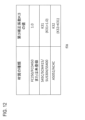
- FIG. 12 shows control information relating to material information to be applied to the first actuator among the processing conditions, among the device control information.
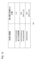
- FIG. 13 shows control information relating to material information to be applied to the second actuator among the processing conditions, among the device control information.
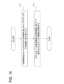
- FIG. 14 is a flowchart showing the process flow of the machine tool control method.
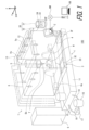
- the machine tool 1 comprises a numerical control device 2, a base 3, a table 4 on which a workpiece W is placed, a spindle unit 5 configured to mount at least one tool T, a housing 6, a switchboard 9, a coolant supply device 10, a chip collector device 20, and a mist collector device 30.
- the machine tool 1 comprises a spindle moving device 5a that holds the spindle unit 5 and moves the spindle unit 5 in the X-axis, Y-axis, and Z-axis directions of FIG. 1.
- the machine tool 1 comprises a table moving device 4a that moves the table 4 in the X-axis and Y-axis directions of FIG. 1.
- the numerical control device 2 includes an electronic circuit such as an electronic control unit, an information processing means such as a hardware processor 2P, and a storage means such as a memory 2M (see FIG. 2).
- the hardware processor 2P controls the spindle moving device 5a and the table moving device 4a, and controls the tool T to rotate.
- the numerical control device 2 includes a control panel 2CP such as a touch panel display that allows input and output of information to and from an operator.
- the touch panel of the control panel 2CP may be referred to as an input interface 2IF, and the display of the control panel 2CP may be referred to as a display 2DS.
- the numerical control device 2 may further include an input interface 2IF such as a button or a dial in addition to the touch panel.
- the coolant supply device 10 includes a coolant tank 11, multiple nozzles 12, multiple coolant supply paths 13, a first pump device 15, a second pump device 16, a chip removal filter 17, and a circulation circuit 18.
- the base 3 includes an outlet 3E connected to the coolant tank 11 provided in the center of the base 3, and multiple raised floors 3F sloping downward toward the outlet 3E.
- the coolant tank 11 is configured to store coolant.
- the multiple coolant supply paths 13 connect the multiple nozzles 12 to the coolant tank 11.
- the multiple nozzles 12 are attached to the machine tool 1 and configured to spray coolant.
- the first pump device 15 is configured to pump up coolant from the coolant tank 11 and supply it to the multiple nozzles 12 through the multiple coolant supply paths 13. The coolant is sprayed from multiple nozzles 12 onto the workpiece W being machined, removing chips.
- the second pump device 16 and the chip removal filter 17 are connected to the coolant tank 11 via a circulation circuit 18 that is different from the multiple coolant supply paths 13.
- the second pump device 16 is configured to pump up coolant from the coolant tank 11 and supply it to the chip removal filter 17 through the circulation circuit 18.
- the chip removal filter 17 removes chips contained in the coolant.
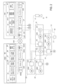
- the numerical control device 2 is a type of computer and includes a hardware processor 2P, a memory 2M, a display 2DS, an input interface 2IF, a system bus 2SB, an external I/O interface 2IO, and a communication interface 2CF.
- the system bus 2SB includes an address bus, a data bus, and a control bus, as in a general computer.
- the external I/O interface 2IO is connected to an external device (e.g., the first pump device 15, the second pump device 16, the chip collector device 20, and the fan device 33).
- This external device may be referred to as at least one peripheral device.
- the at least one peripheral device includes at least one of the coolant supply device 10 including the first pump device 15 and the second pump device 16, the chip collector device 20, and the fan device 33.
- the communication interface 2CF is connected to the network CW.
- the hardware processor 2P is programmed to read the default setting value from the device control information 43, read the value of the control signal corresponding to the default setting value, and output a control signal corresponding to at least one peripheral device.
- the hardware processor 2P executes the machining program 41 to control the spindle unit 5.
- the hardware processor 2P executes the device control program 42 to control at least one peripheral device.
- the device control program 42 has an instruction to cause the hardware processor 2P to execute the execution process of the machining program 41 shown in FIG. 13, etc., which will be described later.
- the individual data 44 is set with the material of the workpiece W to be machined for each machining program 41, and is associated with the workpiece number WNo.
- the first pump device 15 includes a first inverter 15I, a first motor 15M, and a first pump 15P.
- the first inverter 15I drives the first motor 15M in response to a drive signal from the numerical control device 2 transmitted via the external I/O interface 2IO.
- the first inverter 15I controls the rotation speed/operation frequency of the first motor 15M in response to the drive signal from the numerical control device 2.
- the first motor 15M rotates the swash plate of the first pump 15P.
- the first pump 15P is connected to the coolant tank 11.
- the first pump 15P is configured to discharge coolant from the coolant tank 11 and supply the coolant to the multiple nozzles 12.
- the first motor 15M may be referred to as a first actuator.
- the first actuator (first motor 15M) is configured to drive a pump (first pump 15P) that supplies coolant to the nozzle 12 of the machine tool 1.
- the switchboard 9 includes a power source PS that supplies electricity to the first inverter 15I.
- the power source PS is preferably an AC power source.
- the second actuator (second motor 16M) is configured to drive a pump (second pump 16P) that supplies coolant containing chips stored in the coolant tank 11 to the chip removal filter 17.
- the power supply PS of the switchboard 9 also supplies electricity to the second inverter 16I.
- the fan device 33 of the mist collector device 30 includes a fourth inverter 33I and a fourth motor 33M.
- the fourth inverter 33I drives the fourth motor 33M in response to a drive signal from the numerical control device 2 transmitted via the external I/O interface 2IO.
- the fourth inverter 33I controls the rotation speed/operation frequency of the fourth motor 33M in response to the drive signal from the numerical control device 2.
- the fourth motor 33M is configured to drive a belt conveyor via a reduction gear or the like (not shown).
- the fourth motor 33M may be referred to as a fourth actuator.
- the fourth actuator (fourth motor 33M) is configured to drive a fan (fan device 33) for discharging mist accumulated in the body of the machine tool 1.
- the power source PS of the switchboard 9 also supplies electricity to the fourth inverter 33I.
- the computer 99 is used, for example, to generate the machining program 41.
- the computer 99 has installed therein a machining simulation program that displays the work shape before machining and creates the final product shape so that it is contained within the work shape.
- the computer 99 is configured to automatically generate the machining program 41 based on the results of the machining simulation.
- the computer 99 includes a hardware processor 99P, a memory 99M, a display 99DS, an input interface 99IF, a system bus 99SB, and a communication interface 99CF that have substantially the same functions as the hardware processor 2P, the memory 2M, the display 2DS, the input interface 2IF, the system bus 2SB, and the communication interface 2CF, respectively.
- the memory 2M and the memory 99M may each be referred to as a storage device.
- Programs such as a machining program generation program 45, material information 46, shape information 47, tool information 48, machine constant data 49, and an operating system are installed in the memory 99M of the computer 99, and the memory 99M is configured to store programs such as a machining program generation program 45, material information 46, shape information 47, tool information 48, machine constant data 49, and an operating system.
- Material information 46 includes reference information (material information, ID, etc.) of the material that will be the workpiece W to be machined, the workpiece shape (outer diameter, inner diameter (if a hole is present), length), and characteristics (specific cutting resistance x (kg/mm2).
- Shape information 47 is data that defines the product shape. This is generated by the machining simulation program described above.
- Tool information 48 includes the T number corresponding to the tool T that can be attached to the machine tool 1, the name of the tool T, the material of the tool T, the characteristics of the blade of the tool T, and the usage condition (wear condition) of the tool T.
- the characteristics of the blade of the tool T include the nominal diameter, tool length, tool diameter, axial offset, radial offset, number of blades, blade width, blade shape
- the information includes the radius of curvature R of the arc (the radius of curvature of the cutting edge) that defines the cutting edge, the indexing angle of the blade, the effective spindle rotation direction, and the blade orientation.
- the machine constant data 49 is a parameter specific to the machine tool 1 that is used in calculating the cutting conditions.
- the cutting conditions of the tool T include the cutting speed Vc, the cutting depth of the tool T into the workpiece W, and the feed speed of the workpiece W.
- the machine constant data 49 is, for example, the machine efficiency ⁇ , the machine horsepower HP (HP), and the machining limit (finishing allowance).
- the material information 46, the shape information 47, the tool information 48, and the machine constant data 49 are read by a machining simulation program.
- the tool information 48 and the machine constant data 49 may be periodically updated to data corresponding to the latest settings of the
- the machining program generation program 45 is typically a part of the machining simulation program and is a program that generates the machining program 41 including the additional information 41a for controlling at least one of the peripheral devices described above. However, the machining program generation program 45 may be a program separate from the machining simulation program.
- the hardware processor 99P When the machining program generation program 45 is executed by the computer 99, the hardware processor 99P generates the machining program 41 including the additional information 41a for controlling at least one of the peripheral devices described above based on the material information 46, the shape information 47, the tool information 48, and the machine constant data 49 stored in the memory 99M.
- the hardware processor 99P may generate the machining program 41 including the additional information 41a based on the program code not including the additional information 41a, the material information 46, the shape information 47, the tool information 48, and the machine constant data 49 stored in the memory 99M.
- the machining program 41 generated by the computer 99 is sent to the numerical control device 2 via the communication interface 99CF, the network NW, and the communication interface 2CF.
- ⁇ Processing flow of the method for generating the machining program 41> 3 is a flowchart showing a process flow of a method for generating a machining program 41 according to an embodiment.
- step S11 the method includes having the computer 99 calculate cutting information obtained from a cut portion obtained by excluding the product shape from the workpiece shape based on the workpiece shape and the product shape.
- the hardware processor 99P executing the machining program generation program 45 calculates cutting information obtained from a cut portion obtained by excluding the product shape from the workpiece shape based on the workpiece shape stored in the memory 99M as the material information 46 and the product shape stored in the memory 99M as the shape information 47.
- step S12 the method includes generating a program code representing at least one of the operations of the workpiece W and at least one tool T by the machine tool 1 to machine the workpiece W to obtain the product shape.
- step S12 the hardware processor 99P executing the machining program generation program 45 generates a program code representing at least one of the operations of the workpiece W and at least one tool T by the machine tool 1 to machine the workpiece W to obtain the product shape.
- This program generation method is a method in which a known method such as International Publication No. 2004/038522 is applied to a program in the EIA/ISO format. If the program code has already been generated, step S12 may be omitted.
- the generation method includes having the computer 99 generate a machining program 41 in which additional information 41a is added to the program code.
- the hardware processor 99P that executes the machining program generation program 45 generates the machining program 41 in which additional information 41a is added to the program code.
- the additional information 41a includes cutting information, machining information representing machining conditions when the machine tool 1 operates at least one of the workpiece W and at least one tool T, and control codes G181 and G182 (described later) for causing the machine tool 1 to execute a process for controlling at least one peripheral device (e.g., the first pump device 15, the second pump device 16, the chip collector device 20, and the fan device 33) other than the first device (e.g., the table moving device 4a described above) that operates the workpiece W and the second device (e.g., the spindle moving device 5a and the motor 5b for rotating at least one tool T in the spindle unit 5) among the multiple devices of the machine tool 1 based on the machining information and the cutting information.
- at least one peripheral device e.g., the first pump device 15, the second pump device 16, the chip collector device 20, and the fan device 33
- the first device e.g., the table moving device 4a described above
- the second device e.g., the spindle moving device 5a
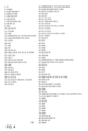
- FIG. 4 shows an example of a machining program 41 generated by the machining program generation program 45.
- the machining program 41 is written in the EIA/ISO format.
- line numbers are added to the left end of the program code for convenience of explanation.
- lines that do not include control codes G181 and G182 described later represent program codes that represent the operation of at least one of the workpiece W and at least one tool T by the machine tool 1.
- the removal rate is a value obtained by dividing the volume (unit: cc, inch 3 ) cut in a predetermined process of the machining program 181 by the time required for the process (unit: min).
- the removal rate is a parameter represented by the size of at least a part of the cut portion, and is an example of cutting information.
- the cutting information includes a parameter represented by the size of at least a part of the cut portion.
- the parameter represented by the size of at least a part of the cut portion is not limited to the volume of at least a part of the cut portion, but includes all values that depend on the size of at least a part of the cut portion that can be detected by a sensor or a driver of a motor that rotates a tool, such as the weight of at least a part of the cut portion, the workload (load x time) of at least one tool T for cutting at least a part of the cut portion, and the amount of heat generated when cutting at least a part of the cut portion.
- the removal rate described as an argument of the control code G181 is a value obtained by dividing the volume of the entire cut portion, which is the entire work shape excluding the entire product shape, by the entire time required for the machining program 41.
- the control code G182 and its arguments are inserted as additional information 41a in line number 14.
- the number with the identifier R among the arguments indicates the removal rate applied in the process until the next control code G182 is called (line number 35).
- the removal rate here is a value obtained by dividing the volume (unit: cc, inch 3 ) of at least a part of the cut part cut in the process from line number 14 to line number 35 by the machining time (unit: min) required to cut with the tool with T number 23.
- the processor 99P executing the machining program generation program 45 can calculate the removal rate in the steps from line number 14 to line number 35 as follows.
- the processor 99P executing the machining program generation program 45 may calculate the volume of at least a portion of the cut part for each machining part, estimate the machining time from the feed rate of the generated program code to calculate the removal rate, and insert control code G182 with the removal rate as an argument immediately before the program code based on the EIA/ISO format generated for each machining part.
- the processor 99P executing the machining program generation program 45 which generates a machining program based on the EIA/ISO format by the method of International Publication No. 2004/038522 may, for example, calculate the removal rate corresponding to each machined body part, and insert control code G182 with the calculated removal rate as an argument immediately before the source code for machining the machined body part.
- the number with the identifier T indicates the tool diameter (unit: mm or inch) applied in the process until the next control code G182 is called (line number 35).
- the number with the identifier S indicates the tool rotation speed (unit: rev/min) applied in the process until the next control code G182 is called (line number 35).
- the tool diameter and tool rotation speed are examples of machining conditions when performing at least one operation. In other words, the machining information includes the tool diameter and the tool rotation speed.
- the processor 99P that executes the machining program generation program 45 that generates a machining program based on the EIA/ISO format by the method of WO 2004/038522 can, for example, determine the tool diameter by referring to the tool information 48 (tool definition section 21 in WO 2004/038522) from the T code indicating the tool corresponding to each machining shape body part.
- the processor 99P executing the machining program generation program 45 that generates a machining program based on the EIA/ISO format by the method of International Publication No. 2004/038522 can obtain the tool rotation speed specified by the parameter input control unit 13 from the T code representing the tool corresponding to each machining shape body part.
- the tool information 48 of the present application also includes data representing the tool rotation speed specified by the parameter input control unit 13.
- the processor executing the machining program generation program 45 can obtain the tool diameter by referring to the tool information 48 from the T number (T23) of the tool used in the process when the process from line number 14 to line number 35 is specified by user input, etc.
- the processor executing the machining program generation program 45 can obtain the tool rotation speed by referring to the code (line number 15) representing the spindle rotation speed in the process when the process from line number 14 to line number 35 is specified by user input, etc.
- additional information 41a including control code G182 and the above-mentioned removal rate, tool diameter, and rotation speed is shown.
- the additional information 41a in line 35 is applied in the process from line 35 to line 57.
- the method for determining the value of this additional information is the same as the additional information 41a in line 14, so an explanation will be omitted.
- the method for determining the value of this additional information is the same as the additional information 41a in line 14, so an explanation will be omitted.
- the machining direction includes the tool diameter and the rotation speed, but may also include the peripheral speed and material information of the workpiece W.
- the peripheral speed may be represented by a number with an identifier V added to the end of the control code G182, and the number may be represented as the value of the peripheral speed (unit: m/min or feet/min).
- the processor that executes the machining program generation program 45 can obtain the peripheral speed by referring to a code (a code with an identifier F and a number added) that represents a peripheral speed effective in the process applied to the control code G182.
- material information of the workpiece W may be further included as a machining condition of an argument of the control code G181.
- the material information may be represented by a number with an identifier M added to the end of the control code G181, and the number corresponds to the material.
- FC250 may be represented as 1, FCD450 as 2, S45C as 3, SCM415 as 4, SUS304 as 5, SS400 as 6, A5052 as 7, AC4C as 8, etc.
- FC250 and FCD450 are cast iron alloys.
- S45C, SCM415, SUS304, and SS400 are steel alloys.
- A5052 and AC4C are aluminum alloys. Therefore, the larger the number after the identifier M, the softer the metal.
- the processor that executes the machining program generation program 45 can refer to the material information 46 to determine the material information.
- the machining program 41 with the additional information 41a thus generated is sent to the numerical control device 2 of the machine tool 1 via the network NW, for example.
- the numerical control device 2 processes the additional information 41a of the machining program 41 as follows.
- the hardware processor 99P that executes the machining program 41 acquires the workpiece number WNo. at the beginning of the machining program 41, and acquires the material information corresponding to the workpiece number WNo. by referring to the individual data 44.
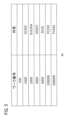
- FIG. 5 is a diagram showing the details of the individual data 44.
- the individual data 44 includes the correspondence between the workpiece number WNo. and the material information. Although the correspondence is shown in a table in FIG. 5, the correspondence may be described in a known manner such as a csv file format or a database. In the example of FIG. 4 and FIG. 5, since the workpiece number WNo. is 1000, the material can be determined to be SC45C.
- an interface for inputting the material e.g., a drop-down window
- FC250 or FCD450 which are cast iron alloys, may be set as the default.
- the hardware processor 99P executing the machining program 41 refers to the argument of the control code G181 and reads the removal rate applied to the part of the peripheral devices described above, or the default removal rate applied to the remaining peripheral devices described above. That is, the hardware processor 99P reads the cutting information according to the control code G181.
- the hardware processor 99P controls the part of the peripheral devices (e.g., the second pump device 16) based on the cutting information and machining information and by referring to the device control information 43 shown in Figures 6 to 12 throughout the entire execution time of the machining program 41.
- the default removal rate for the remaining peripheral devices e.g., the first pump device 15, the chip collector device 20, and the fan device 33
- the hardware processor 99P also reads the material information by referring to the argument of the control code G181.
- the hardware processor 99P executing the machining program 41 changes the tool to the tool with T number 23 according to the code in line number 11, and then reads the control code G182 in line number 14.
- the hardware processor 99P references the arguments of the control code G182 to read the cutting information and machining information.
- the hardware processor 99P references the equipment control information 43 shown in Figures 6 to 12 to control the remaining peripheral equipment (e.g., the first pump device 15, the chip collector device 20, and the fan device 33).
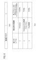
- FIG. 6 shows data 43a1 and 43a2 for controlling the first actuator (first motor 15M) in the device control information 43.
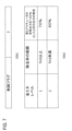
- FIG. 7 shows data 43b1 and 43b2 for controlling the second actuator (second motor 16M) in the device control information 43.
- FIG. 8 shows data 43c1 and 43c2 for controlling the third actuator (third motor 20M) in the device control information 43.
- FIG. 9 shows data 43d1 and 43d2 for controlling the fourth actuator (fourth motor 33M) in the device control information 43.
- Data 43a1 to 43d1 include flags indicating whether the peripheral devices are some to which only control code G181 is applied, or the remaining peripheral devices are to which control code G181 or control code G182 is applied.
- Data 43a2 to 43d2 each include a correspondence relationship between the range of removal rate, the energy saving level, and the output ratio when the rated output of the first to fourth actuators is taken as 100%.
- 6 to 9 show the correspondence relationship in a table, but the correspondence relationship may be described in a known manner such as a csv file format or a database.
- the control flag "2" of data 43b2 indicates that only the control code G181 is applied to some of the peripheral devices.
- the control flag "1" of data 43a2, 43c2, and 43d2 indicates that the remaining peripheral devices apply the control code G181 or the control code G182.
- This control flag is editable, and by editing the control flag, the operator can switch at least one peripheral device to at least one of the peripheral devices that apply only the control code G181 and the remaining peripheral devices that apply the control code G181 or the control code G182.
- data 43a2 to 43d2 include multiple energy saving levels corresponding to multiple ranges of the removal rate.
- the energy saving level is a value that indicates the ratio of each output in percentage when the output when each of the first to fourth actuators is driven at the rated power consumption is 100%.
- the number of different energy saving levels is set in the first to fourth actuators.
- the range of the removal rate for determining each energy saving level is set independently in the first to fourth actuators.
- the threshold values TH1 to TH9 shown in FIGS. 6 to 9 are empirically determined values, and some of the threshold values TH1 to TH9 may be the same value.
- the output ratio is an empirically determined value, and a value different from the value shown in FIGS.
- This output ratio corresponds to the control method of at least one peripheral device. Therefore, the multiple control methods of at least one peripheral device are respectively associated with multiple ranges of a parameter (removal rate) represented by the size of at least a part of the cut part.
- the memory 2M stores information representing a first correspondence between a plurality of ranges of the removal rate and a plurality of energy saving levels corresponding to the plurality of ranges of the removal rate, and information representing a second correspondence between the plurality of energy saving levels and a plurality of control methods of at least one peripheral device.
- the plurality of control methods are defined so that the output of at least one peripheral device is reduced as the energy saving level increases.
- the plurality of energy saving levels are defined so that the output of at least one peripheral device is increased as the removal rate decreases.
- the memory 2M stores only the energy saving level value, the thresholds TH1 to TH9, and the output ratio value among the contents shown in FIG. 6 to FIG.
- the hardware processor 2P executing the device control program 42 may use the data stored in the memory 2M to determine the output ratio based on the criteria shown in FIG. 6 to FIG. 9. In this way, the hardware processor 2P executing the device control program 42 can determine the determined control method corresponding to the additional information 41a among at least one control method (more preferably, a plurality of control methods) of at least one peripheral device stored in the memory 2M. More specifically, the hardware processor 2P that executes the device control program 42 can determine the determined control method based on the processing information and cutting information.
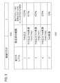
- FIG. 10 shows control information 43e relating to the tool diameter and tool rotation speed among the machining conditions in the equipment control information 43.
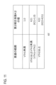
- FIG. 11 shows control information 43f relating to the circumferential speed among the machining conditions in the equipment control information 43.
- FIG. 12 shows control information 43g relating to the material information to be applied to the first actuator (first motor 15M) among the machining conditions in the equipment control information 43.
- FIG. 13 shows control information 43h relating to the material information to be applied to the second actuator (second motor 16M) among the machining conditions in the equipment control information 43.
- the control information 43e includes a first correction coefficient K1 that is multiplied by the output ratio set according to the removal rate shown in FIG. 6.
- the control information 43f includes a second correction coefficient K2 that is multiplied by the output ratio set according to the removal rate shown in FIG. 6.
- the control information 43g includes a third correction coefficient K3 that is multiplied by the output ratio set according to the removal rate shown in FIG. 6.
- the control information 43h includes a fourth correction coefficient K4 by which the output ratio set according to the removal rate shown in Fig. 7 is multiplied.
- the control information 43e includes a correspondence relationship between the range of tool diameter x tool rotation speed and the first correction coefficient K1.
- the control information 43f includes a correspondence relationship between the range of peripheral speed and the second correction coefficient K2.
- the control information 43g includes a correspondence relationship between material information and the third correction coefficient K3.
- the control information 43h includes a correspondence relationship between material information and the fourth correction coefficient K4.
- correspondence relationships are shown in a table in Figs. 10 to 13, the correspondence relationships may be described in a known manner such as a csv file format or a database.
- memory 2M stores only the threshold values MTH1 to MTH2, VTH1 to VTH2, identifiers representing the respective materials, and the values of the first to third correction coefficients K1 to K3, and hardware processor 2P executing device control program 42 may use the data stored in memory 2M to determine the first to fourth correction coefficients K1 to K4 based on the criteria shown in Figures 10 to 13.
- the first correction coefficient K1 is set so that the larger the tool diameter x tool rotation speed, the greater the first correction coefficient K1.
- the output of the first actuator is set to be greater as the tool diameter x tool rotation speed increases.
- the second correction coefficient K2 is set so that the larger the circumferential speed, the greater the second correction coefficient K2.
- the softer the material the greater the scattering of chips, and the more coolant is required to discharge the chips.
- the softer the material the greater the third correction coefficient K3 is set so that the third correction coefficient K3 is set so that the softer the material, the greater the output of the first actuator.
- the softer the material the greater the output of the first actuator.
- the greater the specific gravity of the material the faster the flow rate of the coolant must be in order to carry the chips through the circulation circuit 18.
- the fourth correction coefficient K4 is set so that the greater the specific gravity, the greater the fourth correction coefficient K4 becomes.
- the greater the specific gravity the greater the output of the second actuator is set.
- the first correction coefficient K1 determined from the range of the tool diameter x tool rotation speed of the argument of the control code G182 is K1(i)
- the second correction coefficient determined from the range of the circumferential speed of the argument of the control code G182 is K2(i)
- the third correction coefficient determined from the material information of the control code G182 is K3(i).
- P1 out (i) is expressed by the following (Equation 1).
- P1 out (i) K1(i) ⁇ K2(i) ⁇ K3(i) ⁇ P1(i) (Formula 1)
- P2 out (i) is expressed by the following (Equation 2).
- P2 out (i) K4(i) ⁇ P2(i) (Formula 2)
- K1(i) 1.
- K2(i) 1.
- K3(i) 1.
- K4(i) 1.
- P1 out (i) 100%.
- P2 out (i) 100%.
- the hardware processor 2P that executes the device control program 42 controls the first to second actuators based on the P1 out (i) and P2 out (i) thus obtained.
- the hardware processor 2P executing the device control program 42 controls the third to fourth actuators by referring to the correspondences in Figures 8 and 9. If the machining program 41 does not include the additional information 41a, the hardware processor 2P executing the device control program 42 controls the first to fourth actuators by setting the default setting value to 100%. In this way, the hardware processor 2P executing the device control program 42 can operate at least one peripheral device (e.g., the first pump device 15, the second pump device 16, the chip collector device 20, and the fan device 33) based on the determined control method.
- peripheral device e.g., the first pump device 15, the second pump device 16, the chip collector device 20, and the fan device 33
- the hardware processor 2P executing the equipment control program 42 can control the machine tool 1 to operate at least one peripheral device (e.g., the first pump device 15, the second pump device 16, the chip collector device 20, and the fan device 33) other than the first device that operates the workpiece W and the second device that operates at least one tool T among the multiple devices of the machine tool 1 based on the cutting information when the machine tool 1 performs at least one operation.
- the peripheral device e.g., the first pump device 15, the second pump device 16, the chip collector device 20, and the fan device 33
- control codes G181 and G182 are codes that cause the machine tool 1 to determine a determined equipment control method corresponding to the cutting information among multiple control methods of at least one peripheral device that are respectively associated with multiple ranges of parameters (removal rates) stored in the memory 2M, and cause the machine tool to execute a process of operating at least one peripheral device based on the determined control method.
- the control method includes, in step S22, controlling the machine tool 1 so as to operate at least one peripheral device (e.g., the first pump device 15, the second pump device 16, the chip collector device 20, and the fan device 33) other than the device (first device) that operates the workpiece W and the device (second device) that operates the at least one tool T, among the multiple devices of the machine tool 1, based on cutting information (e.g., removal rate).
- the control method includes causing the hardware processor 2P of the machine tool 1 to determine a determined control method corresponding to the additional information 41a, among at least one control method of at least one peripheral device stored in the memory 2M of the machine tool 1, and causing the at least one peripheral device to operate based on the determined control method.
- the control method includes having the hardware processor 2P determine a determined control method based on machining information (e.g., tool diameter, tool rotational speed, peripheral speed, material information) and cutting information (e.g., removal rate).
- the control method includes having the hardware processor 2P of the machine tool 1 determine a determined device control method corresponding to a parameter of the cutting information from device control information 43 stored in the memory 2M of the machine tool 1 and defining a plurality of control methods of at least one peripheral device associated with a plurality of ranges of a parameter (e.g., removal rate) represented by the size of at least a part of the shape to be cut.
- machining information e.g., tool diameter, tool rotational speed, peripheral speed, material information
- cutting information e.g., removal rate
- the machine tool 1, machine tool system 100, control method for the machine tool 1, generation method for the machining program 41, and program related to the generation method according to the present embodiment obtain cutting information from the part to be cut, and therefore can control at least one peripheral device based on a highly accurate cutting amount. Also, the machine tool 1, machine tool system 100, control method for the machine tool 1, generation method for the machining program 41, and program related to the generation method according to the present embodiment include cutting information in the machining program 41, thereby enabling flexible control of at least one peripheral device for different machine tools.
- the above-described machine tool system 100 shows an example in which data is exchanged between the machine tool 1 and the computer 99 via the communication interface 99CF, the network NW, and the communication interface 2CF.
- data may also be exchanged via short-range wireless communication such as Bluetooth (registered trademark) or Near Field Communication, or an interface with an external storage device such as a USB or SD interface. Therefore, the communication interface 99CF and the communication interface 2CF may be simply referred to as the interfaces 99CF and 2CF as a concept that includes these interfaces.
- Some of the above data 43a1 to 43d1 and 43a2 to 43d2 may be omitted, and the actuators corresponding to the omitted data may not be controlled by the additional information 41a.
- the parameter represented by the size of at least a portion of the cut portion is not limited to the removal rate, but may be the weight of at least a portion of the cut portion divided by the processing time, the workload (load x time) of at least one tool T for cutting at least a portion of the cut portion divided by the processing time, or the amount of heat generated during cutting at least a portion of the cut portion divided by the processing time.
- a part or all of the logic functions of the above-mentioned device control program 42 and machining program generation program 45 may be realized by a dedicated processor or integrated circuit.
- the above-mentioned device control program 42 and machining program generation program 45 may be recorded not only in the memory 2M, 99M built into the numerical control device 2 or computer 99, but also in a storage medium that is removable from the numerical control device 2 or computer 99 and readable by the numerical control device 2 or computer 99, such as a floppy disk, optical disk, CD-ROM or magnetic disk, SD card, USB memory, or external hard disk.
- member can have multiple meanings, such as a single part or multiple parts.
- ordinal numbers such as “first” and “second” are simply terms used to identify a configuration and have no other meaning (such as a particular order). For example, the presence of a “first element” does not imply the presence of a “second element,” and the presence of a “second element” does not imply the presence of a "first element.”
- Words expressing degree, such as “substantially,” “about,” and “approximately,” can refer to reasonable deviations that do not significantly change the end result. All numerical values described in this application can be interpreted to include words such as “substantially,” “about,” and “approximately.”
Landscapes
- Engineering & Computer Science (AREA)
- Physics & Mathematics (AREA)
- Manufacturing & Machinery (AREA)
- Human Computer Interaction (AREA)
- General Physics & Mathematics (AREA)
- Automation & Control Theory (AREA)
- Geometry (AREA)
- Numerical Control (AREA)
- Auxiliary Devices For Machine Tools (AREA)
Abstract
Description
<実施形態>
<工作機械1の構成>
図1は、本発明の実施形態に係る工作機械1を含む工作機械システム100の構成を示すブロック図である。工作機械システム100は、工作機械1と工作機械1にネットワークNWを介して接続されるコンピュータ99とを含む。コンピュータ99は、ハードウェアプロセッサやメモリのような電子回路を含む汎用コンピュータであってもよい。コンピュータ99は、工作機械1で使用される加工プログラムを作成するために用いられる。ネットワークNWは、イントラネットなどの有線ネットワークでも無線LANなどの無線ネットワークでもよい。
<加工プログラム41の生成方法の処理の流れ>
図3は、実施形態に係る加工プログラム41の生成方法の処理の流れを表すフローチャートである。ステップS11として、当該生成方法は、ワーク形状と製品形状とに基づいてワーク形状から製品形状を除いた被切削部分から得られる切削情報をコンピュータ99に算出させることを含む。具体的には、ステップS1において、加工プログラム生成プログラム45を実行するハードウェアプロセッサ99Pは、素材情報46としてメモリ99Mに記憶されているワーク形状と形状情報47としてメモリ99Mに記憶されている製品形状とに基づいて、ワーク形状から製品形状を除いた被切削部分から得られる切削情報を算出する。ステップS12として、当該生成方法は、ワークWを加工して製品形状を得るための、工作機械1によるワークWと少なくとも1つの工具Tとの少なくとも一方の操作を表すプログラムコードを生成することを含む。具体的には、ステップS12において、加工プログラム生成プログラム45を実行するハードウェアプロセッサ99Pは、ワークWを加工して製品形状を得るための、工作機械1によるワークWと少なくとも1つの工具Tとの少なくとも一方の操作を表すプログラムコードを生成する。このプログラム生成方法は、例えば、国際公開第2004/038522号のような周知の方法をEIA/ISOフォーマットのプログラムに適用した方法である。なお、このプログラムコードがすでに生成されている場合、ステップS12は省略されてもよい。ステップS13として、当該生成方法は、このプログラムコードに、付加情報41aが加えられた加工プログラム41をコンピュータ99に生成させることを含む。具体的には、ステップS13において、加工プログラム生成プログラム45を実行するハードウェアプロセッサ99Pは、このプログラムコードに付加情報41aが加えられた加工プログラム41を生成する。
<付加情報41aを含む加工プログラム41>
図4は、加工プログラム生成プログラム45によって生成される加工プログラム41の一例を示す。加工プログラム41は、EIA/ISOフォーマットで記述されている。図4は、説明の便宜上、プログラムコードの左端に行番号を付している。図4において後述する制御コードG181、G182が含まれていない行は、工作機械1によるワークWと少なくとも1つの工具Tとの少なくとも一方の操作を表すプログラムコードを表す。図4において、行番号2において、識別子O(アルファベットのオー)の後にワーク番号WNo.が数字で記載されている。行番号3で、付加情報41aとして制御コードG181とその引数が挿入されている。引数のうち識別子Rを付した数字は、少なくとも1つの周辺機器のうちの一部の周辺機器に適用される除去率、または、少なくとも1つの周辺機器のうちの残りの周辺機器に対して後述する制御コードG182が適用される範囲内を除いて加工プログラム41全体で適用される除去率をいう。除去率とは、加工プログラム181の所定の工程において切削された体積(単位:cc、inch3)を当該工程の所用時間(単位:min)で割った値である。除去率は、被切削部分の少なくとも一部の大きさによって表されるパラメータであって、切削情報の一例である。つまり、切削情報は、被切削部分の少なくとも一部の大きさによって表されるパラメータを含む。被切削部分の少なくとも一部の大きさによって表されるパラメータとは、被切削部分の少なくとも一部の体積に限らず、被切削部分の少なくとも一部の重さ、被切削部分の少なくとも一部を切削するための少なくとも1つの工具Tの仕事量(負荷×時間)、被切削部分の少なくとも一部の切削の際に生じた熱量など、センサや工具を回転させるモータのドライバによって検出可能な被切削部分の少なくとも一部の大きさに依存する全ての値を含む。制御コードG181の引数として記載される除去率は、全体のワーク形状から全体の製品形状を除いた全体の被切削部分の体積を、加工プログラム41の全体の所用時間で割った値である。
<加工プログラム41の工作機械1における処理>
このように生成された付加情報41a付きの加工プログラム41は、例えば、ネットワークNWを介して工作機械1の数値制御装置2に送られる。数値制御装置2は、以下のように加工プログラム41の付加情報41aを処理する。加工プログラム41を実行するハードウェアプロセッサ99Pは、加工プログラム41の冒頭にあるワーク番号WNo.を取得し、個別データ44を参照してワーク番号WNo.に対応する材質情報を取得する。図5は、個別データ44の詳細を示した図である。個別データ44は、ワーク番号WNo.と材質情報の対応関係を含む。図5では対応関係をテーブルで示しているが、csvファイル形式やデータベースなど周知の方法で対応関係が記述されてもよい。図4と図5との例では、ワーク番号WNo.が1000であるため、材質をSC45Cと求めることができる。
P1out(i)=K1(i)×K2(i)×K3(i)×P1(i) (式1)
制御コードG182(i)(i=1、2、…。iは、加工プログラム41において出現する順番に対応する。)の引数の除去率の範囲から定まる第2アクチュエータの出力の割合(図6において示される割合)をP2(i)とし、制御コードG182の材質情報から定まる第4補正係数をK4(i)とする。このとき、機器制御プログラム42を実行するハードウェアプロセッサ2Pは、第2アクチュエータの出力の定格出力を100%としたときの出力の割合P2out(i)とすると、P2out(i)は以下の(式2)によって表される。
P2out(i)=K4(i)×P2(i) (式2)
なお、制御コードG182の引数によって工具径と工具回転速度との少なくとも1つが設定されていないとき、K1(i)=1とする。制御コードG182の引数によって周速が設定されていないとき、K2(i)=1とする。個別データ44または制御コードG181の引数によって材質情報が設定されていないとき、K3(i)=1とする。個別データ44または制御コードG181の引数によって材質情報が設定されていないとき、K4(i)=1とする。また、(式1)の値が100%を超えるときは、P1out(i)=100%とする。(式2)の値が100%を超えるときは、P2out(i)=100%とする。機器制御プログラム42を実行するハードウェアプロセッサ2Pは、このように求められたP1out(i)、P2out(i)に基づいて、第1~第2アクチュエータを制御する。機器制御プログラム42を実行するハードウェアプロセッサ2Pは、図8、図9の対応関係を参照して、第3~第4アクチュエータを制御する。なお、加工プログラム41に付加情報41aが含まれていない場合、機器制御プログラム42を実行するハードウェアプロセッサ2Pは、デフォルトの設定値として100%として、第1~第4アクチュエータを制御する。このように、機器制御プログラム42を実行するハードウェアプロセッサ2Pは、少なくとも1つの周辺機器(例えば、第1ポンプ装置15、第2ポンプ装置16、チップコレクタ装置20、及び、ファン装置33)を被決定制御方法に基づいて動作させることができる。
<実施形態の作用及び効果>
本実施形態に係る工作機械1、工作機械システム100、工作機械1の制御方法、加工プログラム41の生成方法、及び、当該生成方法に係るプログラムは、切削情報を被切削部分から得ているため、精度の高い切削量に基づき、少なくとも1つの周辺機器の制御を行うことができる。また、実施形態に係る工作機械1、工作機械システム100、工作機械1の制御方法、加工プログラム41の生成方法、及び、当該生成方法に係るプログラムは、切削情報を加工プログラム41に含めることにより、異なる工作機械に対して少なくとも1つの周辺機器の制御を柔軟に行うことができる。
<変形例>
上述の工作機械システム100は、工作機械1とコンピュータ99との間のデータの受け渡しは、通信インタフェース99CF、ネットワークNW、及び、通信インタフェース2CFを介した例を示している。しかし、Bluetooth(登録商標)やNear Field Communicationなどの近距離無線通信、USB、SDインタフェースなどの外部記憶装置とのインタフェースなどを介してデータの受け渡しがされてもよい。したがって、通信インタフェース99CF、通信インタフェース2CFは、これらのインタフェースを含める概念として単にインタフェース99CF、2CFと呼称されてもよい。
Claims (15)
- 工作機械によるワークと少なくとも1つの工具との少なくとも一方の操作を表すプログラムコードとワーク形状から製品形状を除いた被切削部分から得られる切削情報を少なくとも有する付加情報を含む加工プログラムを前記工作機械のプロセッサに読み取らせ、
前記工作機械が前記少なくとも一方の操作を実行する際に、前記工作機械の複数の機器のうち前記ワークを操作する機器と前記少なくとも1つの工具を操作する機器以外の少なくとも1つの周辺機器を前記切削情報に基づいて動作させるように前記工作機械を制御する、
ことを含む、工作機械の制御方法。
- 前記付加情報は、前記切削情報に基づいて前記少なくとも1つの周辺機器を制御する処理を前記工作機械に実行させる制御コードをさらに含み、
前記加工プログラムを前記工作機械に読み取らせることは、前記制御コードに応じて前記切削情報を前記工作機械に読み取らせることを含み、
前記工作機械を制御することは、
前記工作機械の記憶装置に記憶された前記少なくとも1つの周辺機器の少なくとも1つの制御方法のうち、前記付加情報に対応する被決定制御方法を前記プロセッサに決定させることと、
前記少なくとも1つの周辺機器を前記被決定制御方法に基づいて動作させることと、
を含む、
請求項1に記載の工作機械の制御方法。
- 前記付加情報は、前記少なくとも1つの操作を行う際の加工条件を表す加工情報をさらに含み、
前記工作機械を制御することは、前記加工情報と前記切削情報とに基づいて前記被決定制御方法を前記プロセッサに決定させることを含む、
請求項2に記載の工作機械の制御方法。
- 前記切削情報は、前記被切削部分の少なくとも一部の大きさによって表されるパラメータを含み、
前記工作機械を制御することは、
前記工作機械の記憶装置に記憶された、前記パラメータの複数の範囲にそれぞれ対応付けられた前記少なくとも1つの周辺機器の複数の制御方法のうち、前記切削情報の前記パラメータに対応する被決定機器制御方法を前記プロセッサに決定させることと、
前記少なくとも1つの周辺機器を前記被決定制御方法に基づいて動作させることと、
を含む、
請求項1から3のいずれかに記載の工作機械の制御方法。
- 前記パラメータは、前記被切削部分の少なくとも一部の体積を前記少なくとも1つの工具によって切削するために要する加工時間で除した除去率を含む、
請求項1から4のいずれかに記載の工作機械の制御方法。
- 前記記憶装置は、
前記除去率の複数の範囲と、前記複数の範囲にそれぞれ対応する複数の省エネルギーレベルとの第1の対応関係を表す情報と、
前記複数の省エネルギーレベルと、前記少なくとも1つの周辺機器の前記複数の制御方法との第2の対応関係を表す情報と、
を記憶し、
前記複数の制御方法は、前記省エネルギーレベルが大きくなればなるほど、前記少なくとも1つの周辺機器の出力が減少されるように規定される、
請求項5に記載の工作機械の制御方法。
- 前記少なくとも1つの周辺機器は、前記工作機械中の、クーラント供給装置と、チップコンベアと、ミストコレクタのうちの少なくとも1つを含む、
請求項1から6のいずれかに記載の工作機械の制御方法。
- ワーク形状と製品形状とに基づいて前記ワーク形状から前記製品形状を除いた被切削部分から得られる切削情報をコンピュータに算出させることと、
ワークを加工して前記製品形状を得るための、工作機械による前記ワークと少なくとも1つの工具との少なくとも一方の操作を表すプログラムコードに、前記切削情報を少なくとも有する付加情報が加えられた加工プログラムをコンピュータに生成させることと、
を含む、プログラムの生成方法。
- 前記付加情報は、前記切削情報に基づいて前記工作機械の複数の機器のうち前記ワークを操作する機器と前記少なくとも1つの工具を操作する機器以外の少なくとも1つの周辺機器を制御する処理を前記工作機械に実行させる制御コードをさらに含む、
請求項8に記載のプログラムの生成方法。
- 前記付加情報は、前記少なくとも一方の操作を行う際の加工条件を表す加工情報をさらに含み、
前記制御コードは、前記加工情報と前記切削情報とに基づいて前記少なくとも1つの周辺機器を制御する処理を前記工作機械に実行させるコードである、
請求項9に記載のプログラムの生成方法。
- 前記切削情報は、前記被切削部分の少なくとも一部の大きさによって表されるパラメータを含み、
前記制御コードは、前記工作機械の記憶装置に記憶された、前記パラメータの複数の範囲にそれぞれ対応付けられた前記少なくとも1つの周辺機器の複数の制御方法のうち、前記切削情報の前記パラメータに対応する被決定機器制御方法を前記工作機械に決定させ、前記少なくとも1つの周辺機器を被決定制御方法に基づいて動作させる処理を前記工作機械に実行させるコードである、
請求項8から10のいずれかに記載のプログラムの生成方法。
- 前記切削情報は、前記被切削部分の少なくとも一部の体積を、前記少なくとも一方の操作によって切削するために要する加工時間で除した除去率を含む、
請求項8から11のいずれかに記載のプログラムの生成方法。
- コンピュータによる実行時に、請求項8から12のいずれかに記載のプログラムの生成方法の処理を前記コンピュータに実行させる指示を備えるプログラム。
- 請求項1から7のいずれかの工作機械の制御方法を実行する手段を備える工作機械。
- 請求項8から12のいずれかに記載のプログラムの生成方法を実行する手段を備えるコンピュータと、
請求項14に記載の工作機械と、
を備える工作機械システム。
Priority Applications (5)
| Application Number | Priority Date | Filing Date | Title |
|---|---|---|---|
| PCT/JP2023/031014 WO2025046708A1 (ja) | 2023-08-28 | 2023-08-28 | 工作機械、工作機械システム、プログラム、工作機械の制御方法、及び、プログラムの生成方法 |
| JP2024513235A JP7531749B1 (ja) | 2023-08-28 | 2023-08-28 | 工作機械、工作機械システム、プログラム、工作機械の制御方法、及び、プログラムの生成方法 |
| CN202380089847.9A CN120457402A (zh) | 2023-08-28 | 2023-08-28 | 机床、机床系统、程序、机床的控制方法和程序的生成方法 |
| EP23950659.5A EP4625074A4 (en) | 2023-08-28 | 2023-08-28 | MACHINE TOOL, MACHINE TOOL SYSTEM, PROGRAM, MACHINE TOOL CONTROL METHOD AND PROGRAM GENERATION METHOD |
| US19/319,732 US20260003339A1 (en) | 2023-08-28 | 2025-09-05 | Machine tool, machine tool system, computer, machine tool control method, and program generation method |
Applications Claiming Priority (1)
| Application Number | Priority Date | Filing Date | Title |
|---|---|---|---|
| PCT/JP2023/031014 WO2025046708A1 (ja) | 2023-08-28 | 2023-08-28 | 工作機械、工作機械システム、プログラム、工作機械の制御方法、及び、プログラムの生成方法 |
Related Child Applications (1)
| Application Number | Title | Priority Date | Filing Date |
|---|---|---|---|
| US19/319,732 Continuation US20260003339A1 (en) | 2023-08-28 | 2025-09-05 | Machine tool, machine tool system, computer, machine tool control method, and program generation method |
Publications (1)
| Publication Number | Publication Date |
|---|---|
| WO2025046708A1 true WO2025046708A1 (ja) | 2025-03-06 |
Family
ID=92174310
Family Applications (1)
| Application Number | Title | Priority Date | Filing Date |
|---|---|---|---|
| PCT/JP2023/031014 Pending WO2025046708A1 (ja) | 2023-08-28 | 2023-08-28 | 工作機械、工作機械システム、プログラム、工作機械の制御方法、及び、プログラムの生成方法 |
Country Status (5)
| Country | Link |
|---|---|
| US (1) | US20260003339A1 (ja) |
| EP (1) | EP4625074A4 (ja) |
| JP (1) | JP7531749B1 (ja) |
| CN (1) | CN120457402A (ja) |
| WO (1) | WO2025046708A1 (ja) |
Citations (7)
| Publication number | Priority date | Publication date | Assignee | Title |
|---|---|---|---|---|
| JPH07251347A (ja) * | 1994-03-16 | 1995-10-03 | Okuma Mach Works Ltd | Nc加工機のコンベア制御装置 |
| JPH07266185A (ja) | 1994-03-28 | 1995-10-17 | Okuma Mach Works Ltd | Nc工作機械の切削液量制御装置 |
| WO2004038522A1 (ja) | 2002-10-25 | 2004-05-06 | Sigma Inc. | Cadシステム並びにこれを実行するためのプログラム及びこのプログラムを記録した記録媒体 |
| JP2005138259A (ja) * | 2003-11-10 | 2005-06-02 | Makino Milling Mach Co Ltd | 工作機械の切屑搬送装置 |
| JP2017199256A (ja) | 2016-04-28 | 2017-11-02 | ファナック株式会社 | 切粉堆積量を求める数値制御装置 |
| JP2019064820A (ja) * | 2017-10-04 | 2019-04-25 | 榎本ビーエー株式会社 | チップコンベアの制御方法及びチップコンベア |
| JP7303958B1 (ja) * | 2022-11-02 | 2023-07-05 | ヤマザキマザック株式会社 | 数値制御装置、工作機械、工作機械の消費電力の制御方法、プログラム、及び、コンピュータ読み取り可能な記憶媒体 |
Family Cites Families (3)
| Publication number | Priority date | Publication date | Assignee | Title |
|---|---|---|---|---|
| JP6751790B1 (ja) * | 2019-03-15 | 2020-09-09 | Dmg森精機株式会社 | 工作機械の切り屑処理装置及び切り屑処理方法 |
| US12059751B2 (en) * | 2020-03-27 | 2024-08-13 | Mitsubishi Electric Research Laboratories, Inc. | System and method for detecting and correcting laser-cutting distortion |
| JP7177905B1 (ja) * | 2021-12-22 | 2022-11-24 | Dmg森精機株式会社 | 情報処理装置 |
-
2023
- 2023-08-28 EP EP23950659.5A patent/EP4625074A4/en active Pending
- 2023-08-28 CN CN202380089847.9A patent/CN120457402A/zh active Pending
- 2023-08-28 WO PCT/JP2023/031014 patent/WO2025046708A1/ja active Pending
- 2023-08-28 JP JP2024513235A patent/JP7531749B1/ja active Active
-
2025
- 2025-09-05 US US19/319,732 patent/US20260003339A1/en active Pending
Patent Citations (7)
| Publication number | Priority date | Publication date | Assignee | Title |
|---|---|---|---|---|
| JPH07251347A (ja) * | 1994-03-16 | 1995-10-03 | Okuma Mach Works Ltd | Nc加工機のコンベア制御装置 |
| JPH07266185A (ja) | 1994-03-28 | 1995-10-17 | Okuma Mach Works Ltd | Nc工作機械の切削液量制御装置 |
| WO2004038522A1 (ja) | 2002-10-25 | 2004-05-06 | Sigma Inc. | Cadシステム並びにこれを実行するためのプログラム及びこのプログラムを記録した記録媒体 |
| JP2005138259A (ja) * | 2003-11-10 | 2005-06-02 | Makino Milling Mach Co Ltd | 工作機械の切屑搬送装置 |
| JP2017199256A (ja) | 2016-04-28 | 2017-11-02 | ファナック株式会社 | 切粉堆積量を求める数値制御装置 |
| JP2019064820A (ja) * | 2017-10-04 | 2019-04-25 | 榎本ビーエー株式会社 | チップコンベアの制御方法及びチップコンベア |
| JP7303958B1 (ja) * | 2022-11-02 | 2023-07-05 | ヤマザキマザック株式会社 | 数値制御装置、工作機械、工作機械の消費電力の制御方法、プログラム、及び、コンピュータ読み取り可能な記憶媒体 |
Non-Patent Citations (1)
| Title |
|---|
| See also references of EP4625074A1 |
Also Published As
| Publication number | Publication date |
|---|---|
| EP4625074A1 (en) | 2025-10-01 |
| JP7531749B1 (ja) | 2024-08-09 |
| CN120457402A (zh) | 2025-08-08 |
| US20260003339A1 (en) | 2026-01-01 |
| JPWO2025046708A1 (ja) | 2025-03-06 |
| EP4625074A4 (en) | 2026-03-18 |
Similar Documents
| Publication | Publication Date | Title |
|---|---|---|
| JP7303958B1 (ja) | 数値制御装置、工作機械、工作機械の消費電力の制御方法、プログラム、及び、コンピュータ読み取り可能な記憶媒体 | |
| JP5792649B2 (ja) | Ncプログラム生成方法 | |
| CN103941643A (zh) | 具有时间推定单元的机床的控制装置 | |
| WO2002003155A1 (en) | Apparatus and method for machining simulation for nc machining | |
| CN105629887A (zh) | 控制具有切削条件变更功能的机床的控制装置 | |
| JP6872087B1 (ja) | 工作機械、工作機械の制御方法、および工作機械の制御プログラム | |
| CN104793559A (zh) | 考虑省电的nc程序产生装置 | |
| JP2016112652A (ja) | 段付工具の寿命管理装置 | |
| JP7531749B1 (ja) | 工作機械、工作機械システム、プログラム、工作機械の制御方法、及び、プログラムの生成方法 | |
| US20150261214A1 (en) | Numerical control unit and nc program creating unit | |
| AU680228B2 (en) | Controller for CNC-operated machine tools | |
| JP4815907B2 (ja) | 加工時間予測方法および予測装置ならびに加工時間予測機能を備えたncデータ編集装置 | |
| TW589234B (en) | Jump control apparatus for electric discharge shaping/profiling machine | |
| JP2005040912A (ja) | 加工装置 | |
| JP2017113849A (ja) | 数値制御工作機械 | |
| JP7039772B1 (ja) | 表示装置、工作機械、および表示方法 | |
| US11992891B2 (en) | Machining method of wire discharge machine, machining program generating device, wire discharge machining system and machined object manufacturing method | |
| JP2019220093A (ja) | 数値制御装置 | |
| JP3152053B2 (ja) | 切削条件設定方法および装置 | |
| JP2008149382A (ja) | 穴加工のためのncデータを生成する方法およびシステム | |
| JPH0236048A (ja) | Ncデータ作成装置 | |
| JP2022091304A (ja) | ワイヤ放電加工機の加工プログラム生成装置、加工プログラム生成方法およびワイヤ放電加工システム | |
| JP2001179519A (ja) | 切削加工方法及びこの切削加工方法を行うためのncデータ作成装置 | |
| JPH10146739A (ja) | 工作機械の工具寿命管理装置 | |
| JP2020119133A (ja) | 計算装置 |
Legal Events
| Date | Code | Title | Description |
|---|---|---|---|
| ENP | Entry into the national phase |
Ref document number: 2024513235 Country of ref document: JP Kind code of ref document: A |
|
| WWE | Wipo information: entry into national phase |
Ref document number: 2024513235 Country of ref document: JP |
|
| 121 | Ep: the epo has been informed by wipo that ep was designated in this application |
Ref document number: 23950659 Country of ref document: EP Kind code of ref document: A1 |
|
| WWE | Wipo information: entry into national phase |
Ref document number: 2023950659 Country of ref document: EP |
|
| ENP | Entry into the national phase |
Ref document number: 2023950659 Country of ref document: EP Effective date: 20250624 |
|
| WWE | Wipo information: entry into national phase |
Ref document number: 202380089847.9 Country of ref document: CN |
|
| WWP | Wipo information: published in national office |
Ref document number: 202380089847.9 Country of ref document: CN |
|
| WWP | Wipo information: published in national office |
Ref document number: 2023950659 Country of ref document: EP |