WO2025057730A1 - Système de commande de mouvement pour machine mobile et procédé de commande de mouvement pour machine mobile - Google Patents
Système de commande de mouvement pour machine mobile et procédé de commande de mouvement pour machine mobile Download PDFInfo
- Publication number
- WO2025057730A1 WO2025057730A1 PCT/JP2024/030595 JP2024030595W WO2025057730A1 WO 2025057730 A1 WO2025057730 A1 WO 2025057730A1 JP 2024030595 W JP2024030595 W JP 2024030595W WO 2025057730 A1 WO2025057730 A1 WO 2025057730A1
- Authority
- WO
- WIPO (PCT)
- Prior art keywords
- unit
- detection
- control system
- distance
- movement control
- Prior art date
- Legal status (The legal status is an assumption and is not a legal conclusion. Google has not performed a legal analysis and makes no representation as to the accuracy of the status listed.)
- Pending
Links
Images



Classifications
-
- C—CHEMISTRY; METALLURGY
- C10—PETROLEUM, GAS OR COKE INDUSTRIES; TECHNICAL GASES CONTAINING CARBON MONOXIDE; FUELS; LUBRICANTS; PEAT
- C10B—DESTRUCTIVE DISTILLATION OF CARBONACEOUS MATERIALS FOR PRODUCTION OF GAS, COKE, TAR, OR SIMILAR MATERIALS
- C10B31/00—Charging devices
- C10B31/12—Charging devices for liquid materials
-
- C—CHEMISTRY; METALLURGY
- C10—PETROLEUM, GAS OR COKE INDUSTRIES; TECHNICAL GASES CONTAINING CARBON MONOXIDE; FUELS; LUBRICANTS; PEAT
- C10B—DESTRUCTIVE DISTILLATION OF CARBONACEOUS MATERIALS FOR PRODUCTION OF GAS, COKE, TAR, OR SIMILAR MATERIALS
- C10B41/00—Safety devices, e.g. signalling or controlling devices for use in the discharge of coke
- C10B41/02—Safety devices, e.g. signalling or controlling devices for use in the discharge of coke for discharging coke
-
- G—PHYSICS
- G05—CONTROLLING; REGULATING
- G05D—SYSTEMS FOR CONTROLLING OR REGULATING NON-ELECTRIC VARIABLES
- G05D1/00—Control of position, course, altitude or attitude of land, water, air or space vehicles, e.g. using automatic pilots
- G05D1/40—Control within particular dimensions
- G05D1/43—Control of position or course in two dimensions [2D]
Definitions
- the present invention relates to a mobile machine movement control system for coke ovens and a mobile machine movement control method.
- Patent Document 1 A mobile machine that runs on rails installed alongside multiple kilns in a coke oven is known.
- the applicant has disclosed a mobile control device for a mobile machine in a coke oven.
- This control device has a position detection unit that detects the position of the mobile machine in the travel direction using a position sensor, and a stop command unit that stops the mobile machine at a target position, and corrects the stop position according to the amount of deviation of the mobile machine in the approaching or leaving direction.
- the movement control system of the mobile machine moves the mobile machine left and right on the rails and controls it to stop at the target kiln core position (target position) in front of the kiln. Since the mobile machine moves a certain braking distance from when braking begins until it stops, the system controls it to start braking before the target position. For this reason, the system predicts the target position and starts braking based on the prediction result. However, if the characteristics of the system change due to aging, etc., the accuracy of predicting the target position decreases and the error in the stopping position increases.
- One exemplary objective of an embodiment of the present invention is to provide a mobile device movement control system that can reduce stopping position errors.
- a mobile control system is a mobile control system that controls a mobile machine that moves along a moving path that extends in a first direction along multiple kilns, and includes multiple detectable objects installed at predetermined intervals in the first direction, a detection unit mounted on the mobile machine that detects the detectable objects, a distance measurement unit that measures the separation distance between the detectable objects and the detection unit, and a control unit that uses the detection results of the detection unit and the measurement results of the distance measurement unit to determine the timing to start braking to stop the mobile machine.
- This method is a movement control method for a mobile machine that moves along a movement path that extends in a first direction along multiple kilns, and includes a detection step of detecting multiple detectable objects installed at predetermined intervals in the first direction by a detection unit mounted on the mobile machine, a measurement step of measuring the distance between the detectable objects and the detection unit, and a step of determining the timing to start braking to stop the mobile machine using the detection results of the detection step and the measurement results of the measurement step.
- the present invention provides a mobile device movement control system that can reduce stopping position errors.
- FIG. 1 is a plan view illustrating a mobility control system according to an embodiment.
- FIG. 2 is a block diagram showing the mobility control system of FIG. 1.
- 2 is a side view showing an example of a detection object, a detection unit, and a distance measurement unit.
- FIG. 4 is a diagram showing the positional relationship between a detection object and a magnetic detection unit.
- FIG. 5 is a diagram showing the relationship between the amount of displacement of a detection object and a detection signal.
- FIG. 2 is a flowchart showing an example of the operation of the mobility control system of FIG. 1 . 4 is a time chart showing an example of the operation of the mobility control system.
- a mobile machine In a coke oven, a mobile machine is moved left and right on the rails of the travel path, stopped at the target kiln core position in front of the oven, and a specified operation is performed. At this time, it is desirable that the deviation of the mobile machine's stopping position from the kiln core position is within the allowable deviation.
- the allowable deviation is ⁇ 5 mm to ⁇ 10 mm. If the deviation exceeds the allowable deviation, the position of the mobile machine will have to be adjusted by an operator, and this adjustment requires additional labor. In addition, the mobile machine cannot be stopped immediately, and moves a certain braking distance between the start of braking and the stop.
- the inventors of the present application therefore came up with a configuration in which the position of the moving machine is identified, and based on the identification results, the braking start time (timing of braking start) of the moving machine is determined, and braking starts just before the stopping position.
- the braking start time of the moving machine can be adjusted according to the braking distance, and the stopping position of the moving machine can be brought closer to the kiln core position.
- the inventors of the present application have also come up with a configuration in which a number of detectable objects are placed at predetermined intervals along the extension direction of the path of travel of the mobile device (hereinafter referred to as the "first direction"), the detectable objects are detected by a detection unit mounted on the mobile device, the position of the mobile device is identified using the detection results, and the timing for starting braking of the mobile device is determined based on the position of the mobile device.
- first direction a number of detectable objects are placed at predetermined intervals along the extension direction of the path of travel of the mobile device
- the inventors of the present application came up with a configuration in which a distance measuring unit is provided to measure the separation distance between the detected object and the detection unit, and the measurement results of the distance measuring unit are used to adjust the timing at which the moving machine starts braking.
- this configuration the process of estimating the separation distance can be almost entirely eliminated, and the effects of changes in the separation distance over time can be reduced, allowing the stopping position of the moving machine to be brought closer to the target kiln core position.
- the inventor of the present application came up with a configuration further including a memory unit that stores a plurality of correction values corresponding to the plurality of detectable objects, and corrects the braking start time of the moving machine using the correction values stored in the memory unit.
- the correction value may be the amount of position change of the detectable object from its initial position (center position). At a predetermined time, the amount of position change of each of the plurality of detectable objects can be measured, and the measurement results can be stored in the memory unit as correction values.
- FIG. 1 is a plan view that shows a schematic diagram of the mobility control system 100 according to the embodiment.
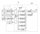
- Figure 2 is a block diagram showing the mobility control system 100.
- the movement control system 100 controls the movement of a moving machine 92 that moves along a moving path 91 that is provided along multiple kilns 90 of a coke oven.
- the moving machine 92 is a coke oven pusher, a guide car, etc.
- the moving path 91 extends in a horizontal first direction (e.g., left-right direction) in front of the kilns 90, and is provided with rails 93 that extend in the first direction.
- the moving machine 92 includes wheels 98, a motor 94 that drives the wheels 98, a drive unit 95, a braking device 96, and a control unit 7.
- the drive unit 95 drives the motor 94 based on the control of the control unit 7.
- the braking device 96 brakes the moving machine 92 to stop it.
- the braking device 96 brakes the wheels 98 by generating a mechanical friction force.
- the control unit 7 controls the drive unit 95 and the braking device 96. Based on the control of the control unit 7, the moving machine 92 travels on the rails 93 in a first direction and stops at a predetermined target position in front of the kiln 90.
- the predetermined target position is the kiln core position of the kiln 90.
- the movement control system 100 includes a plurality of detectable objects 2, a detection unit 3, a distance measuring unit 4, an absolute sensor 5, and a control unit 7.
- the plurality of detectable objects 2 are installed on the ground side at a predetermined interval in the first direction along the movement path 91.
- each detectable object 2 is disposed at the kiln core position of each kiln 90 in the first direction.
- the detection unit 3 is mounted on a moving machine 92 and moves integrally with the moving machine 92.
- the detection unit 3 detects the detectable object 2 and transmits the detection result to the control unit 7.
- the detection unit 3 is separated from the detectable object 2 in a second direction (e.g., vertical direction) perpendicular to the first direction (see FIG. 3).
- each detectable object 2 may be disposed at a position shifted in the first direction as long as the relationship with the kiln core position of each kiln 90 is known.
- the absolute sensor 5 is an absolute rotary encoder that can detect the absolute position of the mobile unit 92 by counting the amount of rotation of the wheels 98 of the mobile unit 92.
- the absolute sensor 5 detects the approximate position of the mobile unit 92 in the first direction, and transmits absolute information S5 as the detection result to the control unit 7.
- FIG. 3 is a side view showing an example of the detected object 2 and the detection unit 3. This figure shows the detected object 2 and the detection unit 3 cut along a plane along the first direction and the second direction.
- the distance measurement unit 4 measures the second direction distance (hereinafter referred to as "separation distance Ds") between the detected object 2 and the detection unit 3, and transmits the measurement result to the control unit 7.
- the distance measurement unit 4 is provided at the same position in the second direction as the two magnetic sensors 34 described later.
- the control unit 7 controls the movement (including stopping) of the mobile device 92.
- the control unit 7 determines the braking start time Ts for stopping the mobile device 92 using the detection result of the detection unit 3 (detection signal S3 described later) and the measurement result of the distance measurement unit 4 (separation distance Ds), and activates the braking device 96 at that time to stop the mobile device 92 at a predetermined position.
- the object to be detected 2 includes a reflecting section 21, an IC tag 22, a magnet 23 for detection, a storage section 24, and an attachment section 25.
- the reflecting section 21 reflects the electromagnetic waves irradiated from the distance measuring section 4 to the distance measuring section 4.
- the reflecting section 21 has a strip shape extending in the first direction, and the main surface, which is the widest surface, faces the distance measuring section 4 in the second direction. In the second direction, the reflecting section 21 and the magnet 23 may have a known height difference, and the distance between the distance measuring section 4 and the reflecting section 21 is related to the distance between the magnetic sensor 34 and the magnet 23.
- the IC tag 22 transmits predetermined information (in this example, kiln number information Q3) to the IC tag sensor 32 provided in the detection unit 3.
- the magnet 23 provides the detection unit 3 with a detectable magnetic field.
- the center of the magnetic pole surface of the magnet 23 in the first direction is referred to as the detectable center C2.
- the position of the detectable object 2 in the first direction means the position of the detectable center C2.
- the storage section 24 is a case that stores the IC tag 22 and the magnet 23, and in this example, is circular when viewed from above and approximately inverted triangular when viewed from the side.
- the attachment section 25 is a rod-shaped member for attaching the storage section 24 to the reflecting section 21.
- the magnet 23 and the IC tag 22 are positioned near the center of the reflecting section 21 in the first direction.
- the detection unit 3 includes a magnetic detection section 31, an IC tag sensor 32, and a sensor housing section 35.
- the IC tag sensor 32 receives kiln number information Q3 from the IC tag 22 attached to the detected object 2, and transmits the kiln number information Q3 to the control section 7.
- the magnetic detection section 31 is a type of non-contact sensor, and has two magnetic sensors 34 that detect the magnetic field from the magnet 23 of the detected object 2.
- the magnetic sensors 34 can be configured to include, for example, a Hall element, a magnetoresistance effect element (MR element, GMR element), etc.
- the magnetic detection section 31 outputs a detection signal S3 according to the distance from the magnet 23 in the first direction.
- the two magnetic sensors 34 are positioned apart from each other in the first direction, and the magnetic detection unit 31 outputs the result of adding a reference value (hereinafter referred to as "reference value R") to the difference between the detection values of the two magnetic sensors 34 (hereinafter simply referred to as “difference D") as a detection signal S3.
- the detection signal S3 is a current value.
- the position that halves the distance in the first direction between the two magnetic sensors 34, and the center in the first direction of the magnetic detection unit 31 is referred to as the "sensor center C3".
- the position in the first direction of the magnetic detection unit 31 means the sensor center C3.
- the sensor center C3 is located at a position equidistant from the two magnetic sensors 34 in the first direction.
- the IC tag sensor 32 is placed at the sensor center C3.
- the sensor housing 35 is a case that houses the magnetic detector 31 and the IC tag sensor 32, and has a rectangular parallelepiped shape in this example.
- the magnetic detector 31 and the IC tag sensor 32 are placed near the end face of the sensor housing 35 on the side of the object to be detected 2.
- VEROLINE registered trademark manufactured by DAMANI can be used as the detection unit 3.
- Figure 4 is a diagram showing the positional relationship between the detected object 2 and the detection unit 3.
- Figure 4(A) shows a state in which the separation distance Ds is the standard 90 mm
- Figure 4(B) shows a state in which the separation distance Ds is 120 mm, which is longer than the standard
- Figure 4(C) shows a state in which the separation distance Ds is 60 mm, which is shorter than the standard.
- the deviation amount K the deviation amount before correction will be referred to as the deviation amount Kd
- the deviation amount after correction will be referred to as the deviation amount Ke.
- FIG. 5 is a diagram showing an example of the relationship of the detection signal S3 to the amount of deviation K.
- FIG. 5(A) shows the change in the detection signal S3 to the amount of deviation K as the magnetic detector 31 approaches the object to be detected 2, passes the object to be detected 2, and then moves away.
- FIG. 5(B) shows an enlarged view of the range of circle B in FIG. 5(A).
- the detection signal S3 when the magnetic detector 31 approaches the object to be detected 2, the sensor center C3 is located on the negative side of the object to be detected C2. When the magnetic detector 31 passes over the object to be detected 2 and moves away, the sensor center C3 is located on the positive side of the object to be detected C2. As shown in FIG. 5(A), when the magnetic detector 31 approaches the object to be detected 2 and passes over the object to be detected 2 and moves away, the detection signal S3 changes in an approximately sinusoidal manner with respect to the change in the amount of deviation K. Note that in the magnetic detector 31 of this embodiment, the detection signal S3 is limited to a range of 12 mA ⁇ 8 mA.
- the change in the detection signal S3 can be considered as a straight line.
- the magnetic detection unit 31 adds a reference value R (e.g., 12 mA) to the difference D and outputs a current of 12 mA as the detection signal S3.
- R e.g., 12 mA
- S3A indicates the case where the separation distance Ds is the standard 90 mm
- S3B indicates the case where the separation distance Ds is 120 mm
- S3C indicates the case where the separation distance Ds is 60 mm.
- the strength of the magnetic field that reaches the magnetic detector 31 changes depending on the separation distance Ds, and therefore the slope of the detection signal S3 changes. In other words, if the separation distance Ds changes from the standard due to changes over time, etc., the slope of the detection signal S3 changes.
- the deviation amount K and the detection signal S3 have the relationship shown in FIG. 5(B), if the relationship between the deviation amount K and the detection signal S3 is acquired and stored in advance, the deviation amount K can be determined from the detection signal S3. However, since the slope of the detection signal S3 differs depending on the separation distance Ds, determining the deviation amount K using the standard S3A characteristics will result in an error.
- the mobility control system 100 of the embodiment includes a distance measurement unit 4 that measures the separation distance Ds, and uses the separation distance Ds to correct the deviation amount Kd before correction and determine the deviation amount Ke after correction. The process of determining the deviation amount Ke will be described later.
- the distance measurement unit 4 will be described with reference to FIG. 3.
- the distance measurement unit 4 of the embodiment has an electromagnetic wave sensor that uses an infrared laser, millimeter waves, or the like as a type of electromagnetic wave.
- the distance measurement unit 4 is a sensor in which an electromagnetic wave emitting side and a light receiving side are integrated, emitting electromagnetic waves to the reflecting unit 21, receiving the electromagnetic waves reflected by the reflecting unit 21, and outputting an output voltage that changes according to the received electromagnetic waves.
- the output voltage of the distance measurement unit 4 changes according to the separation distance Ds, and therefore the separation distance Ds can be determined from the output voltage of the distance measurement unit 4.
- two distance measuring units 4 are provided spaced apart in the first direction.
- the detection unit 3 is disposed between the two distance measuring units 4 in the first direction. In this case, if one of the two distance measuring units 4 faces the reflecting unit 21, the separation distance Ds can be determined even if the other does not face the reflecting unit 21.
- the control unit 7 will be described with reference to FIG. 2.
- the control unit 7 determines the braking start time Ts for stopping the mobile device 92 using the detection signal S3 from the detection unit 3 and the separation distance Ds from the distance measurement unit 4.
- the control unit 7 also activates the braking device 96 at the braking start time Ts to stop the mobile device 92 at a predetermined position.
- control unit 7 shown in FIG. 2 can be realized in hardware terms by computer processors, CPUs, memory and other elements, electronic circuits, and mechanical devices, and in software terms by computer programs, etc., but here we have depicted functional blocks realized by the cooperation of these. Therefore, it will be understood by those skilled in the art that these functional blocks can be realized in various ways by combining hardware and software.
- the control unit 7 includes an acquisition unit 72, a motor control unit 73, a braking control unit 74, a deviation amount identification unit 75, a timing determination unit 76, a threshold determination unit 77, and a memory unit 78. These functional blocks can exchange information via an internal bus 71.
- the acquisition unit 72 acquires a detection signal S3 from the magnetic detection unit 31, kiln number information Q3 from the IC tag sensor 32, the separation distance Ds from the distance measurement unit 4, and absolute information S5 from the absolute sensor 5.
- the motor control unit 73 controls the speed of the motor 94 via the drive unit 95, thereby controlling the direction and speed of movement of the moving machine 92.
- the braking control unit 74 controls the braking device 96 of the mobile unit 92.
- the deviation amount determination unit 75 determines the deviation amount Kd in the first direction between the sensor center C3 and the detected object 2 as the current position of the mobile unit 92 based on the detection signal S3.
- the deviation amount determination unit 75 also corrects the determined deviation amount Kd based on the separation distance Ds, and determines the corrected deviation amount Ke.
- the timing determination unit 76 determines the braking start time Ts based on the deviation amount Ke and the threshold value Hs. In this example, the timing determination unit 76 determines the braking start time Ts based on the timing at which the deviation amount Ke becomes equal to or greater than the threshold value Hs.
- the braking control unit 74 activates the braking device 96 at the braking start time Ts determined by the timing determination unit 76.
- the memory unit 78 stores multiple correction values J corresponding to multiple detectable objects 2, respectively.
- the correction value J is the amount of change in position from the initial position of the kiln (the position of the detectable object 2).
- the correction value J is sometimes referred to as a bias value.
- the amount of change in position of each of the multiple detectable objects 2 can be measured, and the measurement results can be stored in the memory unit 78 as the correction value J.
- the amount of change in position can be measured, and the measurement results can be stored in the memory unit 78 as the correction value J.
- the control unit 7 controls the moving machine 92 to stop at a position shifted by the correction value J from the position of the detectable object 2.
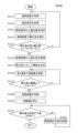
- Process S110 which is an example of the operation of the mobile control system 100, will be described with reference to Figures 6 and 7.
- Figure 6 is a flowchart showing process S110.
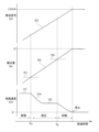
- Figure 7 is a time chart of the operation of the mobile control system 100, showing the detection signal S3 versus elapsed time and the moving speed Vm of the mobile device 92.
- Process S110 is a process for determining the braking start time Ts for stopping the mobile device 92.
- Process S110 is started when it is determined that the moving machine 92 is approaching the target kiln core position while moving in the first direction at a first speed V1, which is the normal moving speed.
- the control unit 7 determines whether or not the moving machine 92 is approaching the kiln core position based on absolute information S5 acquired from the absolute sensor 5.
- control unit 7 acquires the separation distance Ds from the distance measurement unit 4 (step S111).
- the control unit 7 identifies the deviation amount Kd based on the detection signal S3 (step S113).
- the control unit 7 can identify the deviation amount Kd by table processing using the acquired detection signal S3 as a key, using a relationship table between past detection signals S3 and deviation amounts Kd created in advance.
- the relationship table for this step is stored in the memory unit 78.
- control unit 7 corrects the deviation amount Kd based on the separation distance Ds (step S114).
- the control unit 7 can use a relationship table between past separation distances Ds and deviation amounts Kd created in advance to identify the corrected deviation amount Ke by table processing using the acquired separation distance Ds and deviation amount Kd as keys.
- the relationship table for this step is stored in the memory unit 78.
- control unit 7 determines whether the deviation amount Ke is smaller than the first deviation amount K1 (step S115). If the deviation amount Ke is smaller than the first deviation amount K1 (Ke ⁇ K1) (Y in step S115), the control unit 7 returns the process to the beginning of step S111 and executes steps S111 to S115 again.
- the control unit 7 receives the kiln number information Q3 from the IC tag sensor 32 and acquires the correction value J corresponding to the kiln number information Q3 from the memory unit 78 (step S116). Next, the control unit 7 determines the threshold value Hs according to the correction value J (step S117). The timing at which the deviation amount Ke becomes equal to or greater than the first deviation amount K1 is indicated as Tn in FIG. 7.
- control unit 7 decelerates the moving machine 92 and moves the moving machine 92 at a second speed V2 that is slower than the first speed V1 (step S118). After that, the control unit 7 moves the moving machine 92 at the second speed V2 until the braking start time Ts arrives.
- control unit 7 determines whether the deviation amount Ke is smaller than the threshold value Hs (step S119). If the deviation amount Ke is smaller than the threshold value Hs (Ke ⁇ Hs) (Y in step S119), the control unit 7 returns the process to the beginning of step S118 and executes steps S118 to S119 again.
- the control unit 7 activates the braking device 96 (step S120). That is, the control unit 7 determines the braking start time Ts according to the timing at which the mobile device 92 reaches the braking start position and the deviation amount Ke becomes equal to or greater than the threshold value Hs. As an example, the control unit 7 may determine the point at which the deviation amount Ke becomes equal to or greater than the threshold value Hs as the braking start time Ts. The control unit 7 outputs a braking signal to the braking device 96 when the braking start time Ts arrives.
- step S121 When the braking device 96 is activated, the moving machine 92 decelerates while moving the braking distance and stops at approximately the target stop position (step S121).
- the control unit 7 acquires the detection signal S3 and the separation distance Ds to identify the deviation amount Ke, and determines whether the deviation amount Ke (deviation amount from the kiln center position) is within the allowable deviation amount (step S122). If the deviation amount Ke exceeds the range of the allowable deviation amount (N in step S122), the motor 94 is driven by the operator to slightly move the moving machine 92 in the first direction to adjust the position (step S123). After executing step S123, the control unit 7 returns the process to the beginning of step S122 and executes steps S122 to S123 again.
- process S110 ends.
- Each step of process S110 is an example, and various modifications are possible.
- determining the deviation amount Kd (step S113) and correcting the deviation amount Kd (step S114) are separate steps, but these may be integrated into one step.
- the corrected deviation amount Ke may be directly determined by inputting the acquired detection signal S3 and separation distance Ds into a learning model.
- This learning model can be generated by machine learning based on data on past detection signals S3, separation distances Ds, and deviation amount Ke.
- the mobile control system 100 of the embodiment is a mobile control system that controls a mobile machine 92 that moves on a moving path 91 that extends in a first direction along multiple kilns 90, and includes multiple detectable objects 2 installed on the moving path 91 at predetermined intervals in the first direction, a detection unit 3 mounted on the mobile machine 92 and detecting the detectable objects 2, a distance measurement unit 4 that measures the separation distance Ds between the detectable objects 2 and the detection unit 3, and a control unit 7 that determines the braking start time Ts for stopping the mobile machine 92 using the detection results of the detection unit 3 and the measurement results of the distance measurement unit 4.
- the braking start time Ts is determined using the measurement results of the distance measurement unit 4. Therefore, if the separation distance Ds changes over time, an appropriate braking start time Ts is determined in accordance with the change, thereby reducing errors in the stopping position of the mobile device 92.
- the detection unit 3 provides a detection signal S3 according to the detection state of the detected object 2, and the control unit 7 determines the braking start time Ts using the detection signal S3, the separation distance Ds measured by the distance measurement unit 4, and the threshold value Hs.
- the braking start time Ts is determined according to the threshold value Hs, which is a clear standard, so variation in the determination results can be suppressed.
- control unit 7 has a memory unit 78 that stores a correction value J corresponding to the detected object 2, and changes the threshold value Hs according to the correction value J stored in the memory unit 78.
- the braking start time Ts can be corrected according to the shift of the detected object 2 by storing a correction value J according to the amount of shift.
- the object to be detected 2 has a reflecting section 21, and the distance measuring section 4 detects the electromagnetic waves reflected by the reflecting section 21 and determines the separation distance Ds according to the detection result.
- the separation distance Ds can be measured with a simple configuration.
- multiple distance measurement units 4 are arranged at intervals in the first direction. In this case, if one of the multiple distance measurement units 4 faces the reflector 21, the separation distance Ds can be determined even if the others do not face the reflector 21.
- the multiple distance measurement units 4 are arranged on either side of the detection unit 3 in the first direction.
- the separation distance Ds can be determined between the leading side and the lagging side with respect to the detection unit 3.
- the braking device 96 that generates a mechanical friction force on the wheels 98 has been shown, but this is not limiting.
- the braking device may be a type that generates a brake torque in a motor, or a type that combines this type with a friction force type.
- the timing determination unit 76 activates the braking device 96 when the deviation amount Ke becomes equal to or greater than the threshold value Hs, but this is not limiting.
- the timing determination unit may activate the braking device after the deviation amount becomes equal to or greater than the threshold value.
- the deviation amount Kd is determined from the detection signal S3 using a relationship table, but this is not limiting.
- the deviation amount may be determined from the detection signal using a learning model.
- This learning model can be generated by machine learning based on data on past detection signals and deviation amounts.
- the deviation amount after correction may be determined by inputting the deviation amount before correction and the separation distance into a learning model.
- This learning model can be generated by machine learning based on data on past separation distances, deviation amounts, and deviation amounts.
- the present invention can be used in the fields of mobile machine movement control systems and mobile machine movement control methods for coke ovens.
Landscapes
- Chemical & Material Sciences (AREA)
- Engineering & Computer Science (AREA)
- Organic Chemistry (AREA)
- Oil, Petroleum & Natural Gas (AREA)
- Materials Engineering (AREA)
- Remote Sensing (AREA)
- Automation & Control Theory (AREA)
- General Physics & Mathematics (AREA)
- Physics & Mathematics (AREA)
- Radar, Positioning & Navigation (AREA)
- Aviation & Aerospace Engineering (AREA)
- Control Of Position, Course, Altitude, Or Attitude Of Moving Bodies (AREA)
- Control Of Position Or Direction (AREA)
Abstract
Un système de commande de mouvement (100) de la présente divulgation commande une machine mobile (92) qui se déplace dans un trajet de déplacement (91) s'étendant dans une première direction le long d'une pluralité de fours (90). Le système de commande de mouvement comprend : une pluralité de corps d'objet de détection (2) qui sont installés à des intervalles prédéterminés dans la première direction ; une unité de détection (3) qui est montée sur la machine mobile (92) et détecte les corps d'objet de détection (2) ; une unité de mesure de distance (4) qui mesure une distance de séparation (Ds) entre un corps d'objet de détection (2) et l'unité de détection (3) ; et une unité de commande (7) qui détermine une synchronisation de début de freinage (Ts) pour arrêter la machine mobile (92), à l'aide du résultat de détection de l'unité de détection (3) et du résultat de mesure de l'unité de mesure de distance (4).
Applications Claiming Priority (2)
| Application Number | Priority Date | Filing Date | Title |
|---|---|---|---|
| JP2023149017A JP2025042166A (ja) | 2023-09-14 | 2023-09-14 | 移動機の移動制御システム及び移動機の移動制御方法 |
| JP2023-149017 | 2023-09-14 |
Publications (1)
| Publication Number | Publication Date |
|---|---|
| WO2025057730A1 true WO2025057730A1 (fr) | 2025-03-20 |
Family
ID=95022211
Family Applications (1)
| Application Number | Title | Priority Date | Filing Date |
|---|---|---|---|
| PCT/JP2024/030595 Pending WO2025057730A1 (fr) | 2023-09-14 | 2024-08-28 | Système de commande de mouvement pour machine mobile et procédé de commande de mouvement pour machine mobile |
Country Status (3)
| Country | Link |
|---|---|
| JP (1) | JP2025042166A (fr) |
| TW (1) | TWI908331B (fr) |
| WO (1) | WO2025057730A1 (fr) |
Citations (4)
| Publication number | Priority date | Publication date | Assignee | Title |
|---|---|---|---|---|
| JP2010055234A (ja) * | 2008-08-27 | 2010-03-11 | Sumitomo Metal Ind Ltd | 移動機械の位置決め制御方法及び装置 |
| JP2014219935A (ja) * | 2013-05-10 | 2014-11-20 | 住友重機械プロセス機器株式会社 | 移動機械の位置決め制御装置及び移動機械の位置決め方法 |
| JP2014218615A (ja) * | 2013-05-10 | 2014-11-20 | 新日鐵住金株式会社 | コークス炉移動機械の停止制御装置及び停止制御方法。 |
| JP2022166760A (ja) * | 2021-04-21 | 2022-11-02 | 株式会社Ihi | 探傷装置および探傷方法 |
Family Cites Families (2)
| Publication number | Priority date | Publication date | Assignee | Title |
|---|---|---|---|---|
| KR102614845B1 (ko) * | 2019-04-05 | 2023-12-15 | 제이에프이 스틸 가부시키가이샤 | 분율 측정 방법 및 장치 |
| EP3940377A1 (fr) * | 2020-07-16 | 2022-01-19 | 3M Innovative Properties Company | Procédé, ensemble de données et capteur pour détecter une propriété d'un liquide |
-
2023
- 2023-09-14 JP JP2023149017A patent/JP2025042166A/ja active Pending
-
2024
- 2024-08-28 WO PCT/JP2024/030595 patent/WO2025057730A1/fr active Pending
- 2024-09-12 TW TW113134713A patent/TWI908331B/zh active
Patent Citations (4)
| Publication number | Priority date | Publication date | Assignee | Title |
|---|---|---|---|---|
| JP2010055234A (ja) * | 2008-08-27 | 2010-03-11 | Sumitomo Metal Ind Ltd | 移動機械の位置決め制御方法及び装置 |
| JP2014219935A (ja) * | 2013-05-10 | 2014-11-20 | 住友重機械プロセス機器株式会社 | 移動機械の位置決め制御装置及び移動機械の位置決め方法 |
| JP2014218615A (ja) * | 2013-05-10 | 2014-11-20 | 新日鐵住金株式会社 | コークス炉移動機械の停止制御装置及び停止制御方法。 |
| JP2022166760A (ja) * | 2021-04-21 | 2022-11-02 | 株式会社Ihi | 探傷装置および探傷方法 |
Also Published As
| Publication number | Publication date |
|---|---|
| JP2025042166A (ja) | 2025-03-27 |
| TWI908331B (zh) | 2025-12-11 |
| TW202511880A (zh) | 2025-03-16 |
Similar Documents
| Publication | Publication Date | Title |
|---|---|---|
| JP6210642B2 (ja) | ホールセンサによる相対位置の非接触測定のための方法 | |
| JP6113197B2 (ja) | 測定信号記憶部を有する3次元ホールセンサによって相対位置を非接触式に測定する方法 | |
| US11009888B2 (en) | Autonomous vehicle and marking arrangement for an autonomous vehicle | |
| CN108574378A (zh) | 用于确定直线电机的动子的绝对位置的方法 | |
| US8960376B2 (en) | Elevator car position determination and door obstruction avoidance apparatus for an elevator in a three dimensional structure | |
| US7265460B2 (en) | Position detecting device of linear motor | |
| US10474516B2 (en) | Encoder | |
| JP2025042166A (ja) | 移動機の移動制御システム及び移動機の移動制御方法 | |
| JP2012113765A (ja) | 移動体システム | |
| KR20260070401A (ko) | 이동기의 이동제어시스템 및 이동기의 이동제어방법 | |
| CN115328011A (zh) | 一种运行机构行程及位置的检测校准控制方法 | |
| TWI900827B (zh) | 定位裝置、驅動裝置、定位方法及定位程式 | |
| US20090277033A1 (en) | Measuring device for determining a position and/or a speed | |
| WO2021035579A1 (fr) | Appareil et procédé de positionnement secondaire d'un véhicule à guidage automatique | |
| US20030178557A1 (en) | Position encoder | |
| CN111602031B (zh) | 用于检测行程的方法、行程检测装置和制动系统 | |
| CN101435709B (zh) | 用于往复式直线运动物体的定位装置及定位方法 | |
| US20200041309A1 (en) | Sensor system and method for determining a position of a measuring element along a motion path | |
| TWI817561B (zh) | 多感測器位置量測系統 | |
| KR20050121486A (ko) | 긴 구간용으로 사용가능한 위치 검출용 선형 엔코더 | |
| CN114115266B (zh) | Agv磁寻迹偏移量计算方法、存储介质及agv | |
| JP7394924B1 (ja) | マルチセンサー位置計測システム | |
| KR101287071B1 (ko) | 차량감지 신호 교정 시스템 및 교정방법 | |
| KR0161044B1 (ko) | 로보트의 주행제어장치 및 그 주행제어방법 | |
| JPH02236707A (ja) | 無人車の走行制御装置 |
Legal Events
| Date | Code | Title | Description |
|---|---|---|---|
| 121 | Ep: the epo has been informed by wipo that ep was designated in this application |
Ref document number: 24863864 Country of ref document: EP Kind code of ref document: A1 |