WO2025062860A1 - Dispositif de commande de ponction - Google Patents
Dispositif de commande de ponction Download PDFInfo
- Publication number
- WO2025062860A1 WO2025062860A1 PCT/JP2024/027957 JP2024027957W WO2025062860A1 WO 2025062860 A1 WO2025062860 A1 WO 2025062860A1 JP 2024027957 W JP2024027957 W JP 2024027957W WO 2025062860 A1 WO2025062860 A1 WO 2025062860A1
- Authority
- WO
- WIPO (PCT)
- Prior art keywords
- cross
- sectional image
- puncture
- line information
- control unit
- Prior art date
- Legal status (The legal status is an assumption and is not a legal conclusion. Google has not performed a legal analysis and makes no representation as to the accuracy of the status listed.)
- Pending
Links
Images





Classifications
-
- A—HUMAN NECESSITIES
- A61—MEDICAL OR VETERINARY SCIENCE; HYGIENE
- A61B—DIAGNOSIS; SURGERY; IDENTIFICATION
- A61B8/00—Diagnosis using ultrasonic, sonic or infrasonic waves
- A61B8/13—Tomography
- A61B8/14—Echo-tomography
Definitions
- the present invention relates to a puncture control device that determines the acquisition state of a cross-sectional image of the human body acquired by an ultrasound probe in order to perform a puncture.
- Vascular puncture involves inserting a needle into the human body to secure an access route to blood vessels for drug administration or intravascular treatment.
- the surgeon cannot see the blood vessels from the surface of the skin, so they estimate the location of the blood vessels using standard knowledge of vascular anatomy and skills such as palpation of vascular pulsation.
- Patent Document 1 In recent years, devices that perform vascular puncture automatically have become available (see, for example, Patent Document 1).
- a device that automatically performs vascular punctures uses an ultrasound probe to obtain cross-sectional images of the human body, calculates the target puncture position based on this cross-sectional image, and controls the drive of the needle toward the calculated target puncture position. In order to perform the puncture at the correct position, it is necessary for the ultrasound probe to obtain clear images.
- An ultrasonic probe emits ultrasonic waves from the probe surface in contact with the human body, and detects the reflected waves from inside the body to obtain cross-sectional images. If the probe surface is not in close contact with the surface of the human body and there is an air gap between the probe surface and the surface of the human body, the ultrasonic waves will not reach the inside of the body, and cross-sectional images cannot be obtained properly.
- the probe surface is either flat or convexly curved, whereas the surface of the human body is a mixture of flat, convexly curved, and concavely curved parts, and often does not match the shape of the probe surface.
- the operator When an operator manually operates an ultrasound probe, the operator applies gel to the surface of the human body while viewing the acquired cross-sectional image, and presses the ultrasound probe against the surface of the human body to prevent the presence of air gaps.
- the operator may erroneously detect the position of blood vessels, or may not be able to detect the position of blood vessels, without recognizing that the cross-sectional image has not been acquired correctly.
- the present invention has been made to solve the above-mentioned problems, and aims to provide a puncture control device that can determine the state of a cross-sectional image of the human body acquired by an ultrasound probe.
- the puncture control device (1) which achieves the above-mentioned object, is a puncture control device comprising an ultrasonic probe that contacts the surface of the skin to emit ultrasonic waves and obtain a cross-sectional image of the human body based on the received reflected waves, a puncture unit with a sharp needle tip, a drive unit that moves the puncture unit, and a control unit that causes the ultrasonic probe to obtain the cross-sectional image and operates the drive unit, and the control unit extracts multiple pieces of line information along the transmission direction of the ultrasonic waves from the cross-sectional image obtained by the ultrasonic probe, and determines the acquisition state of the cross-sectional image based on the intensity distribution of the reflected waves contained in the multiple pieces of line information extracted.
- the puncture control device (1) configured as described above can determine whether cross-sectional images are being properly acquired by the ultrasound probe, and can therefore reliably acquire the information necessary to perform the puncture.
- the control unit may determine whether or not the puncture unit can perform puncture based on the determined acquisition state of the cross-sectional image. This allows puncture to be performed reliably.
- the control unit may determine whether the intensity distribution of the reflected waves is proper or defective for each of the extracted line information, and determine that the cross-sectional image has not been acquired normally if the proportion of the line information for which the intensity distribution of the reflected waves is determined to be defective relative to the total number of the extracted line information is equal to or greater than a certain value. This allows for accurate determination of whether the cross-sectional image is normal or not.
- the control unit may determine that the cross-sectional image has not been acquired normally when the line information in which the intensity distribution of the reflected wave is determined to be poor continues for a certain period or more in a direction perpendicular to the direction along the line information. This makes it possible to accurately determine that the cross-sectional image has not been acquired normally because the ultrasound probe has not been in sufficient contact with the surface of the human body.
- the control unit may be configured to determine that the cross-sectional image has not been acquired normally when a certain number or more of the line information in which the intensity distribution of the reflected wave is determined to be poor is present in an area within a certain range from the center position in a direction perpendicular to the direction along the line information. This makes it possible to reliably determine whether the cross-sectional image has been acquired normally near the center of the cross-sectional image where the blood vessels are located, and to accurately estimate the blood vessel positions.
- the control unit may be configured to determine that the cross-sectional image has not been acquired normally when the line information, in which the intensity of the reflected wave periodically increases and decreases multiple times, exists continuously for a certain section or more in a direction perpendicular to the direction along the line information. This makes it possible to reliably determine the state of the cross-sectional image caused by multiple reflections of ultrasound waves by gel applied to the surface of the ultrasound probe, and accurately determine that the cross-sectional image has not been acquired normally.
- the control unit may be configured to determine that the cross-sectional image has not been acquired normally when the line information, in which the intensity distribution of the reflected wave is determined to be poor beyond a certain range from the side where the ultrasound probe is located, exists continuously for a certain section or more in a direction perpendicular to the direction along the line information. This allows the puncture to be continued by treating the acquired cross-sectional image as normal even if the cross-sectional image has not been acquired normally in an area that has little effect on the puncture, and on the other hand, when the cross-sectional image has not been acquired normally in an area that has an effect on the puncture, this can be reliably determined.
- a notification means may be provided that, when the control unit determines that the cross-sectional image has not been acquired normally, issues a notification based on the line information in which the intensity distribution of the reflected wave is determined to be poor. This makes it possible to reliably notify the operator that the cross-sectional image has not been acquired normally.
- a position adjustment unit that changes the position of the ultrasonic probe relative to the skin may be provided, and when the control unit determines that the cross-sectional image has not been acquired normally, the control unit may adjust the position of the ultrasonic probe relative to the skin using the position adjustment unit based on the line information in which the intensity distribution of the reflected wave is determined to be poor. This allows the position of the ultrasonic probe to be automatically adjusted so that the cross-sectional image can be acquired normally.
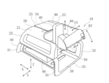
- FIG. 1 is a perspective view of a blood vessel puncture device according to an embodiment of the present invention.
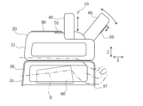
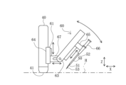
- FIG. 2 is a side view of the vascular puncture device of the present embodiment. 2 is a partial side view of an imaging section and a puncture section of the vascular puncture device.
- FIG. 1 is a diagram showing the positional relationship between the bottom surface of the imaging unit and the arm of a human body.
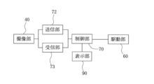
- FIG. 1 is a diagram showing the configuration of a blood vessel puncture device.
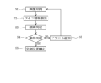
- FIG. 11 is a flow diagram of the operation of the blood vessel puncture device up to the point where the puncture position is determined.
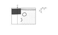
- FIG. 2 is a diagram showing an example of a cross-sectional image acquired by an imaging section, the cross-sectional image having a region that cannot be imaged normally in a part of the image.
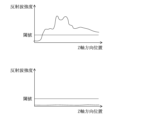
- 8A and 8B are graphs showing the reflected wave intensity distribution versus the Z-axis position in the line information in FIG. 7, where (a) is a graph showing line information A in FIG. 7, and (b) is a graph showing line information B in FIG.
- FIG. 13 is a diagram showing an example of a cross-sectional image acquired by an imaging section, illustrating a cross-sectional image in which a periodic pattern is observed in part of an area that has not been imaged normally.
- 10 is a graph showing a reflected wave intensity distribution versus a Z-axis direction position in the line information in FIG.
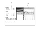
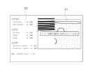
- FIG. 13 is an example of a screen display when a cross-sectional image is not normally acquired by an imaging unit.
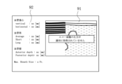
- 13 is a first modified example of a screen display when a cross-sectional image is not normally acquired by the imaging unit.
- 13 is a second modified example of a screen display when a cross-sectional image is not normally acquired by the imaging unit.
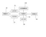
- FIG. 13 is a configuration diagram of a blood vessel puncture device according to a modified example.
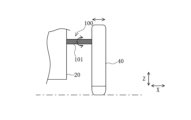
- 13 is a side view showing a support structure for an imaging unit in a blood vessel puncture device according to a modified example.
- FIG. 13 is a front view showing a support structure for an imaging unit in a blood vessel puncture device according to a modified example.
- FIG. 10A and 10B are partial front views showing the imaging unit tilted to one side and the imaging unit tilted to the other side, respectively.
- FIG. 11 is a flow chart showing the process up to determining the puncture position, in the operation of the blood vessel puncture device according to the modified example.
- the puncture control device 10 is used when puncturing the arm H of a human body, acquiring a cross-sectional image of the arm H, detecting the position of the blood vessel to be punctured, and automatically puncturing that blood vessel.
- the puncture control device 10 comprises a main body 20 that automatically punctures a blood vessel, and a support stand 30 that overlaps with the main body 20 in the Z-axis direction and is positioned below the main body 20 to support the main body 20.
- the Z-axis direction which is the height direction, is the direction perpendicular to the horizontal surface when the puncture control device 10 is placed on the horizontal surface.
- the main body 20 comprises an upper frame 21, an imaging unit 40 that contacts the skin surface to obtain a cross-sectional image of the human body, a puncture unit 50 that performs the puncture, a drive unit 60 that moves the puncture unit 50 relative to the imaging unit 40, a control unit 70 that performs image analysis of the cross-sectional image and controls the drive unit 60, and a display unit 90 that can display the cross-sectional image.
- the puncture unit 50 is supported by the drive unit 60.
- the imaging unit 40 is fixed to the upper frame 21, and has an ultrasound probe 41 at its lower end that generates and transmits ultrasound waves and receives reflected waves (echoes) from within the living body.
- the ultrasound probe 41 is provided to extend in one direction (the Y-axis direction) at the center of the probe surface 42, which is the bottom surface, and spans almost the entire width of the probe surface.
- the imaging unit 40 has a transducer that generates ultrasound waves, and can obtain cross-sectional images of the inside of the human body by detecting the reflected waves.
- cross-sectional images perpendicular to the axial direction of the blood vessels are obtained, so the imaging unit 40 is positioned so that its length is perpendicular to the length of the arm H.
- the Y-axis direction, which is the width direction, and the X-axis direction, which is the length direction are perpendicular to each other and perpendicular to the Z-axis direction.
- the main body 20 supports the imaging unit 40 so that it can move in the Z-axis direction.
- the upper frame 21 is formed in a generally arch-like shape that convexly faces upward when viewed from the X-axis direction.
- the upper frame 21 has two upper walls 22 formed on both sides in the Y-axis direction, a top surface 23 connecting the two upper walls 22, and an opening 24 in which the imaging unit 40 and the puncture unit 50 are disposed.
- the upper frame 21 is formed, for example, from a hard resin material.
- Each upper wall 22 has a main body connecting surface 25 at its lower end.
- a display unit 90 that displays an image captured by the imaging unit 40 is disposed on the upward-facing surface of the top surface 23.
- the opening 24 is formed in a concave shape when viewed from above on the peripheral side of the upper frame 21 in the X-axis direction. That is, the top surface 23 is formed shorter on the peripheral side in the X-axis direction than the upper wall 22, thereby forming the opening 24 in the upper frame 21.
- the opening 24 is disposed on the peripheral side of the top surface 23. From the opening 24, the arm H, which is imaged by the imaging unit 40 and punctured by the puncture unit 50, is exposed.
- the imaging unit 40 is connected to the opening 24.
- the imaging unit 40 may be removable from the opening 24, or may not be removable.
- the puncture unit 50 comprises a metal inner needle 51 having a sharp needle tip 53 formed at its tip, and a flexible tubular outer tube 52 arranged to cover the outer periphery of the inner needle 51.
- the needle tip 53 of the inner needle 51 protrudes from the outer tube 52.
- the inner needle 51 and the outer tube 52 are detachable from the puncture direction drive unit 65 of the drive unit 60.
- the drive unit 60 is a drive source that is controlled by the control unit 70 to change the position and/or angle of the puncture unit 50 to automatically adjust the puncture position and perform the puncture operation.
- the drive unit 60 has a height direction drive unit 61 that moves the entire puncture unit 50 up and down (Z-axis direction) relative to the upper frame 21, a rotation drive unit 63 that tilts the entire puncture unit 50, a width direction drive unit 64 that moves the entire puncture unit 50 in the width direction (Y-axis direction) of the arm H, a puncture direction drive unit 65 that moves the inner needle 51 forward and backward in the puncture direction, an outer tube drive unit 66 that moves the outer tube 52 forward and backward along the inner needle 51, and a length direction drive unit 67 that moves the entire puncture unit 50 in the length direction (X-axis direction) of the arm H.
- the puncture unit 50 can be moved in the Z-axis direction by the height direction drive unit 61 independently of the imaging unit 40.
- the drive unit 60 is configured by combining a rotary drive source such as a motor, a structure that converts the rotary motion of the rotary drive source into linear motion (e.g., a feed screw mechanism), and a structure that changes the angle (e.g., a hinge), but the configuration is not limited.
- control unit 70 is connected to the imaging unit 40 via the transmission unit 72 and the reception unit 73, and can cause the imaging unit 40 to acquire cross-sectional images and receive the acquired cross-sectional images.
- the control unit 70 can cause the display unit 90 to display the cross-sectional images acquired by the imaging unit 40.
- the control unit 70 can also control the drive unit 60 to operate the imaging unit 40 and the puncture unit 50 to acquire cross-sectional images and perform puncture.
- the control unit 70 includes, as its physical components, a memory circuit and an arithmetic circuit.
- the memory circuit can store programs and various parameters.
- the arithmetic circuit can perform arithmetic processing.
- the control unit 70 may be disposed in the upper frame 21, or in the imaging unit 40 or the drive unit 60. Alternatively, the control unit 70 may be configured separately from the main body 20.
- the control unit 70 can identify the position of the blood vessel in the image by performing image analysis on the acquired cross-sectional image.
- the control unit 70 can also detect the relative position of the inner needle 51 with respect to the imaging unit 40 by performing image analysis.
- the outer tube 52 is made of resin and therefore cannot be detected by ultrasound. However, for example, if the outer tube 52 is made of resin containing metal, it can be detected by ultrasound, and the control unit 70 can detect the relative position of the outer tube 52 with respect to the imaging unit 40.
- the control unit 70 can also display the cross-sectional image on the display unit 90 by performing image analysis on the acquired cross-sectional image. Furthermore, the control unit 70 can control the drive unit 60 to adjust the position and angle of the puncture unit 50, and automatically perform puncture with the inner needle 51 and outer tube 52 at the desired position and angle.
- the display unit 90 is a monitor or the like capable of displaying a cross-sectional image.
- the display unit 90 is preferably placed near the puncture unit 50 that performs the puncture.
- the display unit 90 is placed, for example, on the upward-facing surface of the top surface 23 adjacent to the opening 24 in which the puncture unit 50 is placed. This allows the surgeon to visually check the skin of the arm H to be punctured while viewing the cross-sectional image of the blood vessel on the display unit 90.
- the display unit 90 may also be placed away from the main body 20 and the support base 30.
- the support base 30 has a lower frame 31 and a holding portion 80 that holds the arm H.
- the lower frame 31 is formed in a generally arch shape that is convex downward when viewed from the X-axis direction.
- the lower frame 31 has two lower walls 32 formed on both sides in the Y-axis direction, and a bottom surface portion 33 that connects the two lower walls 32.
- the lower frame 31 is formed, for example, from a hard resin material.
- the bottom surface portion 33 has a bottom surface 37 that contacts the operating table or the like, and a support surface 38 that faces upward.
- a holding portion 80 that holds the arm H is fixed to the support surface 38.
- the surgeon places the support table 30 on a table such as an operating table, and places the patient's arm H on the holding part 80.
- the arm H is placed on the holding part 80 with the palm side of the wrist bent upwards. This makes it possible to prevent the skin from shifting and the puncture position from shifting during the subsequent puncture.
- the surgeon activates the puncture control device 10.
- the control unit 70 of the puncture control device 10 acquires a cross-sectional image of the human body using the ultrasound probe 41 of the imaging unit 40 (S1).
- the control unit 70 extracts multiple pieces of line information along the transmission direction of the ultrasound from the cross-sectional image acquired by the ultrasound probe 41 (S2).
- the ultrasound transmitted from the ultrasound probe 41 travels in the Z-axis direction, which is the depth direction of the human body, and is reflected and received by the ultrasound probe 41, so that line information including intensity information of the reflected wave can be extracted along the vertical direction of the acquired cross-sectional image, as shown in FIG. 7.
- the control unit 70 extracts line information from multiple different positions in the Y-axis direction from the cross-sectional image, and detects the intensity distribution of the reflected wave included in each piece of line information.
- the control unit 70 can extract line information from the cross-sectional image at regular intervals. However, the control unit 70 may extract all of the line information from the cross-sectional image.
- the control unit 70 determines whether the cross-sectional image has been drawn normally (S3). For each piece of extracted line information, the control unit 70 determines whether the intensity distribution of the reflected wave contained in the line information is appropriate or defective. From the line information at position A in the Y-axis direction in FIG. 7, the control unit 70 detects the intensity distribution of the reflected wave as shown in FIG. 8(a). Also, from the line information at position B in the Y-axis direction in FIG. 7, the control unit 70 detects the intensity distribution of the reflected wave as shown in FIG. 8(b). The image is acquired normally at position A. In this case, the intensity of the reflected wave at position A is higher than a certain threshold at most positions along the Z-axis direction.
- the control unit 70 determines that the intensity distribution of the reflected waves included in the line information is poor if the area where the intensity of the reflected waves included in the line information is lower than a certain threshold continues for a certain percentage or more of the total length in the Z-axis direction, and determines that the intensity distribution of the reflected waves included in the line information is appropriate if the area where the intensity of the reflected waves is lower than a certain threshold does not continue for a certain percentage or more of the total length.
- the certain percentage for determining whether the intensity distribution of the reflected waves is appropriate can be, for example, 30%. However, the certain percentage may be another percentage.
- the intensity of the reflected waves included in the line information can be made greater overall by increasing the gain, so when determining whether an image has been acquired normally based on whether the intensity of the reflected waves exceeds a threshold, it may not be possible to make an accurate determination. For this reason, the control unit 70 may determine that the intensity distribution of the reflected waves included in the line information is poor if an area where the intensity of the reflected waves does not change within a certain range continues for more than a certain percentage of the total length in the Z-axis direction. This makes it possible to determine whether the intensity distribution of the reflected waves is appropriate even when the intensity of the detected reflected waves is greater overall.
- the control unit 70 may determine that the intensity distribution of the reflected waves included in the line information is poor if there is a continuous area where the intensity of the reflected waves is below a threshold value in a portion of the intensity distribution of the reflected waves included in the line information that is below 50% in the Z-axis direction.
- the ultrasonic waves may not reach the inside of the skin because some parts of the ultrasonic probe 41 are not in sufficient contact due to unevenness of the skin, or because there is an air layer in the gel. Even in this case, the ultrasonic waves from the peripheral parts of the ultrasonic probe 41 that are in sufficient contact with the surface of the skin may be able to reach the deeper parts of the skin by diffraction. In this case, the acquired line information has a poor intensity distribution in a certain range from the side where the ultrasonic probe 41 is located, and the intensity distribution beyond that range is normal. Since blood vessels are located at a certain depth from the surface of the skin, even if the intensity distribution of the line information is poor in the area close to the ultrasonic probe 41, it has little effect on puncture.
- control unit 70 may determine that the line information in which the intensity distribution of the reflected wave is poor within a certain range from the side where the ultrasonic probe 41 is located is normal.
- This certain range can be set to a range smaller than 10% of the intensity distribution on the side where the ultrasonic probe 41 is located, for example, a range of 5% of the intensity distribution on the side where the ultrasonic probe 41 is located, when the blood vessels are located at a depth of 2 mm or more from the surface of the skin and the cross-sectional image is acquired up to a position of 20 mm from the surface of the skin.
- the control unit 70 may also determine that the cross-sectional image has not been acquired normally if line information in which the intensity distribution of the reflected wave is judged to be poor beyond a certain range from the side where the ultrasonic probe 41 is located exists continuously for a certain section or more in a direction perpendicular to the direction along the line information.
- the control unit 70 determines that the cross-sectional image has not been acquired normally if the proportion of line information in which the intensity distribution of the reflected wave is determined to be poor among the extracted line information is equal to or greater than a certain percentage.
- the control unit 70 determines that the cross-sectional image has been acquired normally if the proportion of line information in which the intensity distribution of the reflected wave is determined to be poor is less than a certain percentage.
- the certain percentage for determining whether the cross-sectional image has been acquired normally can be, for example, 25%. However, the certain percentage may be a percentage other than this.
- control unit 70 can determine that a cross-sectional image has not been acquired normally when line information in which the reflected wave intensity distribution is determined to be poor exists continuously for a certain section or more in the direction perpendicular to the direction along the line information (Y-axis direction).
- the arm H is positioned relative to the ultrasound probe 41 so that the blood vessels are imaged in the central region of the cross-sectional image.
- the control unit 70 can determine that the cross-sectional image has not been acquired normally when a certain number or more pieces of line information in which the intensity distribution of the reflected wave is determined to be poor are present in a region within a certain range (range R in Figure 7) from the central position in the direction perpendicular to the direction along the line information (Y-axis direction).
- periodic stripes may appear above the area where the cross-sectional image has not been acquired normally. This occurs due to multiple reflections of ultrasound from the gel applied to the surface of the ultrasound probe 41. When such stripes appear, the cross-sectional image has not been acquired normally and this is detected.
- the intensity of the reflected wave increases and decreases at equal intervals along the Z-axis as shown in FIG. 10.
- the control unit 70 can determine that the cross-sectional image has not been acquired normally when line information in which the intensity of the reflected wave periodically increases and decreases multiple times exists continuously for a certain section or more in the direction perpendicular to the direction of the line information (Y-axis direction).
- the control unit 70 determines the subsequent operation based on the judgment result of S3 (S4). If it is judged in S3 that the cross-sectional image has not been acquired normally, the control unit 70 judges that puncture is impossible and issues an alert on the display unit 90 as a notification means (S5). As shown in FIG. 11, the display unit 90 has a cross-sectional image area 91 that displays the cross-sectional image, and an information display area 92 that displays information such as the blood vessel position and blood vessel diameter. The alert is issued by surrounding the area in the cross-sectional image area 91 of the display unit 90 where the image has not been acquired normally and displaying a message saying "Echo image not properly acquired".
- the cause of the cross-sectional image failure may be displayed together with the above message in the cross-sectional image area 91 of the display unit 90.
- the cause of the cross-sectional image failure can be identified as the gel applied to the ultrasound probe 41 containing air, and this cause can be displayed on the display unit 90.
- the alert may be displayed by displaying a line above the area in the cross-sectional image area 91 of the display unit 90 where the image has not been properly acquired, and may also display a message stating "Echo image not properly acquired.”
- the alert may be displayed in a message in the cross-sectional image area 91 of the display unit 90, such as "The left side of the echo image has not been properly acquired.” to indicate which part of the cross-sectional image has not been properly acquired.
- the surgeon adjusts the position of the arm H relative to the ultrasound probe 41 and repeats steps S1 and onwards.
- the control unit 70 determines that puncture is possible and determines the puncture position based on the acquired cross-sectional image (S6).
- the puncture position is determined based on the position of the blood vessel in the cross-sectional image.
- the control unit 70 detects an area recognized as a blood vessel 100 in the cross-sectional image and determines the position of the center of gravity as the position of the blood vessel.
- a machine learning or deep learning method can be used by preparing a large number of similar images. It is also possible to detect an area with blood flow using the Doppler method in the ultrasound probe 41 and recognize the area as a blood vessel area.
- arteries and veins can be distinguished based on the position of the arm bones that appear in the cross-sectional image.
- arteries and veins can also be distinguished based on the direction of the blood flow.
- the drive unit 60 controls the tip of the inner needle 51 to reach the inside of the blood vessel together with the outer tube 52. After this, the drive unit 60 retracts the inner needle 51, leaving the tip of the outer tube 52 inside the blood vessel, and pulls it out of the outer tube 52.
- the inner needle 51 may be retracted manually by the surgeon.
- the surgeon removes both or either of the inner needle 51 and the outer tube 52 from the drive unit 60. Next, the surgeon lifts up the main body 20 and detaches it from the support base 30 to remove it. After removing the main body 20, the surgeon can perform the catheter procedure via the outer tube 52.
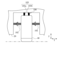
- a position adjustment unit 100 is connected to a control unit 70, and the control unit 70 can adjust the position of the imaging unit 40 having the ultrasound probe 41 by using the position adjustment unit 100.
- the position adjustment unit 100 has an X-direction drive unit 101, a Y-direction drive unit 102, and a tilt drive unit 103, which are provided between the main body 20 and the imaging unit 40.
- the X-direction drive unit 101 has a screw shape and connects the main body 20 and the imaging unit 40 along the X-axis direction.
- the imaging unit 40 can be moved in the X-axis direction by rotating the X-direction drive unit 101.
- the Y-direction drive unit 102 has a screw shape and connects the main body 20 and the imaging unit 40 along the Y-axis direction.
- the imaging unit 40 can be moved in the Y-axis direction by rotating the Y-direction drive unit 102.
- the Y-direction drive unit 102 is supported by the main body 20 so that it can be tilted around the X-axis direction as its central axis.
- the tilt drive unit 103 is formed of two expandable parts 103a and 103b that connect the main body 20 and the top surface of the imaging unit 40.
- the expandable parts 103a and 103b can each independently extend or contract along the length direction. As shown in FIG. 17(a), one expandable part 103a contracts and the other expandable part 103b extends, causing the imaging unit 40 to tilt to one side.
- the Y-direction drive unit 102 also tilts to one side with respect to the main body 20 together with the imaging unit 40. As shown in FIG. 17(b), one expandable part 103a expands and the other expandable part 103b contracts, causing the imaging unit 40 to tilt to the other side.
- the Y-direction drive unit 102 also tilts to the other side with respect to the main body 20 together with the imaging unit 40.
- the control unit 70 acquires a cross-sectional image (S2-1), extracts a number of pieces of line information from the cross-sectional image (S2-2), and determines whether the cross-sectional image has been drawn correctly based on the extracted line information (S2-3). Based on the result of the determination in S2-3, the control unit 70 decides on the subsequent operation (S2-4). If the control unit 70 determines that the cross-sectional image has not been drawn correctly, since there is line information in at least a portion of the area where the intensity distribution of the reflected wave has been determined to be poor, the control unit 70 controls the position adjustment unit 100 to adjust the position of the ultrasound probe 41 relative to the skin so as to eliminate this (S2-5). After the position adjustment is performed, the steps from S2-1 are repeated. If it is determined in S2-3 that the cross-sectional image has been drawn correctly, the puncture position is confirmed (S2-6).
- the puncture control device 10 (1) in this embodiment is a puncture control device 10 that includes an ultrasonic probe 41 that contacts the surface of the skin to emit ultrasonic waves and acquires a cross-sectional image of the human body based on the received reflected waves, a puncture unit 50 with a sharp needle tip, a drive unit 60 that moves the puncture unit 50, and a control unit 70 that causes the ultrasonic probe 41 to acquire a cross-sectional image and operates the drive unit 60, and the control unit 70 extracts multiple pieces of line information along the transmission direction of the ultrasonic waves from the cross-sectional image acquired by the ultrasonic probe 41, and determines the acquisition state of the cross-sectional image based on the intensity distribution of the reflected waves included in the multiple extracted line information.
- the puncture control device 10 configured in this way (1) can determine whether the cross-sectional image has been properly acquired by the ultrasonic probe 41, and can reliably acquire the information necessary to perform puncture.
- control unit 70 may determine whether or not puncture can be performed by the puncture unit 50 based on the determined acquisition state of the cross-sectional image. This allows puncture to be performed reliably.
- the control unit 70 may determine whether the reflected wave intensity distribution is proper or defective for each extracted line information, and determine that the cross-sectional image has not been acquired normally if the proportion of line information for which the reflected wave intensity distribution is determined to be defective relative to the total number of extracted line information is equal to or greater than a certain value. This allows for accurate determination of whether the cross-sectional image is normal or not.
- control unit 70 may be configured to determine that the cross-sectional image has not been acquired normally when line information in which the intensity distribution of the reflected wave is determined to be poor exists continuously for a certain period or more in a direction perpendicular to the direction along which the line information extends. This makes it possible to accurately determine that the cross-sectional image has not been acquired normally because the ultrasound probe 41 has not made sufficient contact with the surface of the human body.
- control unit 70 may be configured to determine that the cross-sectional image has not been acquired normally when a certain number or more pieces of line information in which the intensity distribution of the reflected wave is determined to be poor are present in an area within a certain range from the center position in the direction perpendicular to the direction along the line information. This makes it possible to reliably determine whether the cross-sectional image has been acquired normally near the center of the cross-sectional image where the blood vessels are located, and to accurately estimate the blood vessel positions.
- control unit 70 may be configured to determine that the cross-sectional image has not been acquired normally when line information in which the intensity of the reflected wave periodically increases and decreases multiple times exists continuously for a certain period or more in a direction perpendicular to the direction along the line information. This makes it possible to reliably determine the state of the cross-sectional image caused by multiple reflections of ultrasound waves by the gel applied to the surface of the ultrasound probe 41, and accurately determine that the cross-sectional image has not been acquired normally.
- the control unit 70 may be configured to determine that the cross-sectional image has not been acquired normally when line information in which the intensity distribution of the reflected wave is judged to be poor beyond a certain range from the side where the ultrasound probe 41 is located is present continuously for a certain section or more in a direction perpendicular to the direction along which the line information is aligned. This allows the puncture to be continued by treating the acquired cross-sectional image as normal even if the cross-sectional image has not been acquired normally in an area that has little effect on the puncture, and on the other hand, when the cross-sectional image has not been acquired normally in an area that has an effect on the puncture, this can be reliably determined.
- a notification means may be provided that notifies the operator based on line information in which the intensity distribution of the reflected wave is determined to be poor when the control unit 70 determines that the cross-sectional image has not been acquired normally. This makes it possible to reliably notify the operator that the cross-sectional image has not been acquired normally.
- a position adjustment unit 100 that changes the position of the ultrasonic probe 41 relative to the skin, and when the control unit 70 determines that a cross-sectional image has not been acquired normally, the control unit 70 may adjust the position of the ultrasonic probe 41 relative to the skin using the position adjustment unit 100 based on line information in which the intensity distribution of the reflected wave is determined to be poor. This allows the position of the ultrasonic probe 41 to be automatically adjusted so that a cross-sectional image can be acquired normally.
Landscapes
- Life Sciences & Earth Sciences (AREA)
- Health & Medical Sciences (AREA)
- Biomedical Technology (AREA)
- Biophysics (AREA)
- Nuclear Medicine, Radiotherapy & Molecular Imaging (AREA)
- Pathology (AREA)
- Radiology & Medical Imaging (AREA)
- Engineering & Computer Science (AREA)
- Physics & Mathematics (AREA)
- Heart & Thoracic Surgery (AREA)
- Medical Informatics (AREA)
- Molecular Biology (AREA)
- Surgery (AREA)
- Animal Behavior & Ethology (AREA)
- General Health & Medical Sciences (AREA)
- Public Health (AREA)
- Veterinary Medicine (AREA)
- Ultra Sonic Daignosis Equipment (AREA)
Abstract
La présente invention concerne un dispositif de commande de ponction permettant de distinguer l'état d'une image en coupe transversale d'un corps humain acquise par une sonde ultrasonore. Un dispositif de commande de ponction (10) comprend : une sonde ultrasonore (41) en contact avec la surface de la peau et émettant des ondes ultrasonores pour acquérir une image en coupe transversale du corps humain sur la base des ondes réfléchies reçues ; une unité de ponction (50) dotée d'une pointe d'aiguille acérée ; une unité d'entraînement (60) qui déplace l'unité de ponction (50) ; et une unité de commande (70) qui permet à la sonde ultrasonore (41) d'acquérir une image en coupe transversale et qui fait fonctionner l'unité d'entraînement (60). L'unité de commande (70) extrait une pluralité d'informations de ligne le long d'une direction de transmission des ondes ultrasonores de l'image en coupe transversale acquise par la sonde ultrasonore (41), et distingue un état d'acquisition de l'image en coupe transversale sur la base de la distribution d'intensité des ondes réfléchies incluses dans la pluralité d'informations de ligne extraites.
Applications Claiming Priority (2)
| Application Number | Priority Date | Filing Date | Title |
|---|---|---|---|
| JP2023155462 | 2023-09-21 | ||
| JP2023-155462 | 2023-09-21 |
Publications (1)
| Publication Number | Publication Date |
|---|---|
| WO2025062860A1 true WO2025062860A1 (fr) | 2025-03-27 |
Family
ID=95072685
Family Applications (1)
| Application Number | Title | Priority Date | Filing Date |
|---|---|---|---|
| PCT/JP2024/027957 Pending WO2025062860A1 (fr) | 2023-09-21 | 2024-08-05 | Dispositif de commande de ponction |
Country Status (1)
| Country | Link |
|---|---|
| WO (1) | WO2025062860A1 (fr) |
Citations (6)
| Publication number | Priority date | Publication date | Assignee | Title |
|---|---|---|---|---|
| JPH1156842A (ja) * | 1997-08-15 | 1999-03-02 | Ge Yokogawa Medical Syst Ltd | スクロール表示方法および超音波撮像装置 |
| JP2012024196A (ja) * | 2010-07-21 | 2012-02-09 | Ge Medical Systems Global Technology Co Llc | 超音波画像表示装置及びその制御プログラム |
| JP2013135776A (ja) * | 2011-12-28 | 2013-07-11 | Toshiba Corp | 超音波診断装置 |
| JP5920746B1 (ja) * | 2015-01-08 | 2016-05-18 | 学校法人早稲田大学 | 穿刺支援システム |
| WO2021033491A1 (fr) * | 2019-08-16 | 2021-02-25 | 富士フイルム株式会社 | Appareil de diagnostic à ultrasons et procédé de commande d'un appareil de diagnostic à ultrasons |
| WO2022113844A1 (fr) * | 2020-11-27 | 2022-06-02 | 富士フイルム株式会社 | Dispositif de traitement d'informations, dispositif de diagnostic par ultrasons, procédé de traitement d'informations et programme de traitement d'informations |
-
2024
- 2024-08-05 WO PCT/JP2024/027957 patent/WO2025062860A1/fr active Pending
Patent Citations (6)
| Publication number | Priority date | Publication date | Assignee | Title |
|---|---|---|---|---|
| JPH1156842A (ja) * | 1997-08-15 | 1999-03-02 | Ge Yokogawa Medical Syst Ltd | スクロール表示方法および超音波撮像装置 |
| JP2012024196A (ja) * | 2010-07-21 | 2012-02-09 | Ge Medical Systems Global Technology Co Llc | 超音波画像表示装置及びその制御プログラム |
| JP2013135776A (ja) * | 2011-12-28 | 2013-07-11 | Toshiba Corp | 超音波診断装置 |
| JP5920746B1 (ja) * | 2015-01-08 | 2016-05-18 | 学校法人早稲田大学 | 穿刺支援システム |
| WO2021033491A1 (fr) * | 2019-08-16 | 2021-02-25 | 富士フイルム株式会社 | Appareil de diagnostic à ultrasons et procédé de commande d'un appareil de diagnostic à ultrasons |
| WO2022113844A1 (fr) * | 2020-11-27 | 2022-06-02 | 富士フイルム株式会社 | Dispositif de traitement d'informations, dispositif de diagnostic par ultrasons, procédé de traitement d'informations et programme de traitement d'informations |
Similar Documents
| Publication | Publication Date | Title |
|---|---|---|
| CN108814691B (zh) | 针的超声引导辅助装置及系统 | |
| JP2007159653A (ja) | 穿刺用超音波プローブ及び超音波診断装置 | |
| US20120116227A1 (en) | Ultrasonic blood vessel inspecting apparatus | |
| JP5292581B2 (ja) | 血管撮影装置 | |
| US20180055479A1 (en) | Ultrasound system and method | |
| US20260026779A1 (en) | Contact sensor positioning system, cannula insertion system and method to position a contact sensor | |
| US20240139435A1 (en) | Vascular puncture assistance device | |
| JP2010269067A (ja) | 治療支援装置 | |
| US10213186B2 (en) | Imaging apparatus for diagnosis and probe | |
| EP2390839A1 (fr) | Appareil à ultrasons en 3D et son procédé de fonctionnement | |
| WO2023002933A1 (fr) | Dispositif de perforation vasculaire et système de perforation vasculaire | |
| WO2013051279A1 (fr) | Dispositif de diagnostic à ultrasons et procédé de commande du dispositif de diagnostic à ultrasons | |
| US20170150942A1 (en) | Ultrasonic diagnostic apparatus | |
| US20250221735A1 (en) | Vascular puncture apparatus and method for controlling the same | |
| JP6873975B2 (ja) | 被検体情報取得装置、表示装置、および表示方法 | |
| WO2017037832A1 (fr) | Appareil et procédé d'affichage d'image ultrasonore, et support d'enregistrement contenant un programme | |
| JP2010051337A (ja) | 乳房断層画像撮影装置 | |
| WO2017138086A1 (fr) | Appareil et procédé d'affichage d'images ultrasonores et programme de stockage pour support de stockage | |
| JP7772719B2 (ja) | 血管位置表示器 | |
| WO2023002848A1 (fr) | Dispositif d'assistance à la ponction d'un vaisseau sanguin | |
| JP6714927B2 (ja) | 超音波画像表示装置及び方法、並びにプログラムを格納した記録媒体 | |
| JP5121384B2 (ja) | 超音波診断装置 | |
| JP4300460B2 (ja) | 超音波診断装置 | |
| US20240139434A1 (en) | Vascular puncture device and vascular puncture system | |
| JP6243719B2 (ja) | 生体血管状態測定装置 |
Legal Events
| Date | Code | Title | Description |
|---|---|---|---|
| 121 | Ep: the epo has been informed by wipo that ep was designated in this application |
Ref document number: 24867941 Country of ref document: EP Kind code of ref document: A1 |