WO2025075190A1 - Potence de bicyclette et bicyclette la comprenant - Google Patents
Potence de bicyclette et bicyclette la comprenant Download PDFInfo
- Publication number
- WO2025075190A1 WO2025075190A1 PCT/JP2024/035778 JP2024035778W WO2025075190A1 WO 2025075190 A1 WO2025075190 A1 WO 2025075190A1 JP 2024035778 W JP2024035778 W JP 2024035778W WO 2025075190 A1 WO2025075190 A1 WO 2025075190A1
- Authority
- WO
- WIPO (PCT)
- Prior art keywords
- stem
- torque sensor
- bicycle
- torque
- steering column
- Prior art date
- Legal status (The legal status is an assumption and is not a legal conclusion. Google has not performed a legal analysis and makes no representation as to the accuracy of the status listed.)
- Pending
Links
Images



Classifications
-
- B—PERFORMING OPERATIONS; TRANSPORTING
- B62—LAND VEHICLES FOR TRAVELLING OTHERWISE THAN ON RAILS
- B62J—CYCLE SADDLES OR SEATS; AUXILIARY DEVICES OR ACCESSORIES SPECIALLY ADAPTED TO CYCLES AND NOT OTHERWISE PROVIDED FOR, e.g. ARTICLE CARRIERS OR CYCLE PROTECTORS
- B62J45/00—Electrical equipment arrangements specially adapted for use as accessories on cycles, not otherwise provided for
- B62J45/40—Sensor arrangements; Mounting thereof
- B62J45/41—Sensor arrangements; Mounting thereof characterised by the type of sensor
- B62J45/411—Torque sensors
-
- B—PERFORMING OPERATIONS; TRANSPORTING
- B62—LAND VEHICLES FOR TRAVELLING OTHERWISE THAN ON RAILS
- B62J—CYCLE SADDLES OR SEATS; AUXILIARY DEVICES OR ACCESSORIES SPECIALLY ADAPTED TO CYCLES AND NOT OTHERWISE PROVIDED FOR, e.g. ARTICLE CARRIERS OR CYCLE PROTECTORS
- B62J45/00—Electrical equipment arrangements specially adapted for use as accessories on cycles, not otherwise provided for
- B62J45/40—Sensor arrangements; Mounting thereof
- B62J45/42—Sensor arrangements; Mounting thereof characterised by mounting
-
- B—PERFORMING OPERATIONS; TRANSPORTING
- B62—LAND VEHICLES FOR TRAVELLING OTHERWISE THAN ON RAILS
- B62K—CYCLES; CYCLE FRAMES; CYCLE STEERING DEVICES; RIDER-OPERATED TERMINAL CONTROLS SPECIALLY ADAPTED FOR CYCLES; CYCLE AXLE SUSPENSIONS; CYCLE SIDECARS, FORECARS, OR THE LIKE
- B62K21/00—Steering devices
-
- B—PERFORMING OPERATIONS; TRANSPORTING
- B62—LAND VEHICLES FOR TRAVELLING OTHERWISE THAN ON RAILS
- B62K—CYCLES; CYCLE FRAMES; CYCLE STEERING DEVICES; RIDER-OPERATED TERMINAL CONTROLS SPECIALLY ADAPTED FOR CYCLES; CYCLE AXLE SUSPENSIONS; CYCLE SIDECARS, FORECARS, OR THE LIKE
- B62K21/00—Steering devices
- B62K21/18—Connections between forks and handlebars or handlebar stems
Definitions
- Patent Documents 1 and 2 configurations having torque sensors for assisting bicycle handlebar operation are known.
- neither document discloses specific configurations for the torque sensor, such as the arrangement and mounting structure of the torque sensor.
- the inventors considered attaching a strain gauge to the bicycle stem and using the strain gauge to detect steering torque. In that case, it is necessary to use the strain gauge to accurately detect minute deformations in the bicycle stem. However, it is difficult to accurately detect minute deformations in the bicycle stem using the strain gauge.
- the bicycle stem is a bicycle stem equipped with a torque sensor.
- the torque sensor is configured to detect torque around the X-axis when a force is input from the handlebars or steering column, and is more likely to deform due to torque around the X-axis than torque around the Y-axis and torque around the Z-axis when the same torque is input around each of the orthogonal X, Y and Z axes.
- the bicycle stem includes a first stem having a steering column connection part connected to the steering column and a first torque sensor connection part connected to the torque sensor, and a second stem having a handlebar connection part connected to the handlebars and a second torque sensor connection part connected to the torque sensor.
- the first and second stems are configured such that the handlebar connection parts are located forward of the steering column, and are configured to be less likely to deform than the torque sensor when the same torque is input around the X-axis.
- the stem is divided into two, a first stem and a second stem, and a torque sensor is provided between the first stem and the second stem.
- the torque sensor is more likely to deform than the first stem and the second stem. This makes it possible to increase the signal-to-noise ratio of the torque signal detected by the torque sensor. This therefore makes it possible to improve the accuracy of torque detection by the torque sensor.
- the torque sensor can more easily detect the torque input to the first stem and the second stem.
- the bicycle stem of the present invention may include the following configuration: Between the first stem and the second stem, there is an X-axis rotation restriction portion that restricts the relative rotation of the first stem and the second stem about the X-axis by more than a predetermined angle.
- first stem or the second stem to be connected to a torque sensor, so that the torque applied to the first stem or the second stem can be detected with high accuracy by the torque sensor.
- a bicycle stem is a component that connects the handlebars of a bicycle to a steering column that passes through a head tube.
- the bicycle stem includes an ahead stem that is directly connected to the top of the steering column, and a threaded stem that is connected to the steering column by pressing a fixing member provided at the lower end against the inner surface of the top of the steering column.
- the bicycle may be a two-wheeled vehicle or a three-wheeled vehicle, so long as the rider obtains driving force by rotating the pedals.
- the bicycle may be a vehicle that tilts left and right, or a vehicle that does not tilt left and right.
- Front-rear direction refers to the front-rear direction as seen by a rider riding a bicycle when the bicycle stem is attached to the bicycle.
- a stem in which a torque sensor is compactly arranged so as to have directionality in the measurement direction by utilizing the shape and function of the stem.
- arrow F indicates the forward direction of the vehicle.
- Arrow RR indicates the rearward direction of the vehicle.
- Arrow U indicates the upward direction of the vehicle.
- Arrow D indicates the downward direction of the vehicle.
- Arrow L indicates the leftward direction of the vehicle.
- Arrow R indicates the rightward direction of the vehicle.
- the up-down, left-right, and front-to-back directions respectively refer to the up-down, left-right, and front-to-back directions as seen by a rider riding the bicycle.
- the handle connection part 11 may have a structure other than a clamp structure as long as it can be connected to the handle 2.
- the first torque sensor connection part 12 may have a detachable structure such as a fastening member such as a bolt or a fitting, or may have a non-detachable structure such as a joint or adhesive.
- the first torque sensor connection part 12 may be connected to a case of the torque sensor 30. In this case, the torque sensor 30 can detect rotation around the X-axis by the relative rotation of the part of the torque sensor 30 to which the second torque sensor connection part 22 is connected with respect to the case.
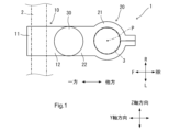
- the second stem 20 is configured to space the torque sensor 30 and the first stem 10 radially from the steering column 3 when viewed in the axial direction of the steering column 3.
- the handle 2 connected to the handle connection portion 11 of the first stem 10 is also spaced radially from the steering column 3 when viewed in the axial direction of the steering column 3.
- the first stem 10 is spaced forward and backward from the second stem 20.
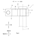
- the first stem 10 and the second stem 20 are configured so that the handle connection portion 11 is located forward of the steering column 3, and are configured so that they are less likely to deform than the torque sensor 30 when the same torque is input around the X-axis.
- the torque sensor 30 is more likely to deform than the first stem 10 and the second stem 20.
- the first stem 10 and the second stem 20 Since at least one of the first stem 10 and the second stem 20 has a detachable connection structure with respect to the torque sensor 30, it is possible to change at least one of the first stem 10 and the second stem 20 and change at least one of the front-rear and up-down positions of the handlebars 2 relative to the steering column 3. This makes it easy to change at least one of the front-rear and up-down positions of the handlebars 2 relative to the steering column 3. Therefore, while providing the torque sensor 30 on the bicycle stem 1, it is possible to ensure the stem's function of adjusting the position of the handlebars 2 relative to the steering column 3.
- the torque sensor 30 is connected to the first stem 10 and the second stem 20, respectively, and constitutes part of the stem. Therefore, the torque sensor 30 is positioned relative to the first stem 10 connected to the handlebar 2 and the second stem 20 connected to the steering column 3. Therefore, the above-mentioned configuration has less variation in the sensor mounting position compared to the case where multiple sensors are provided. This improves the torque detection accuracy.
- first stem 10 and the second stem 20 are configured so that the handle connection portion 11, the first torque sensor connection portion 12, the steering column connection portion 21, and the second torque sensor connection portion 22 are aligned in the fore-and-aft direction when viewed in the axial direction of the steering column 3.
- a torque sensor 30 is provided between the first torque sensor connection portion 12 of the first stem 10 and the second torque sensor connection portion 22 of the second stem 20.
- the handle connection portion 11 of the first stem 10 and the steering column connection portion 21 of the second stem 20 are located radially outward relative to the steering column 3 when viewed in the axial direction of the steering column 3.
- the torque sensor 30 thus positioned relative to the first stem 10 and the second stem 20 can detect the torque applied to the handle 2 or the steering column 3.
- the handlebar connection part 11, the first torque sensor connection part 12, the second torque sensor connection part 22, and the steering column connection part 21 are aligned in the front-rear direction when viewed in the axial direction of the steering column 3. This allows the torque sensor 30 to be positioned compactly in the left-right direction relative to the bicycle stem 1.
- first torque sensor connection portion 12 of the first stem 10 or the second torque sensor connection portion 22 of the second stem 20 may be connected to the case of the torque sensor 30.
- the steering assist motor 77 is located in front of the steering column 3.
- the steering assist motor 77 may be located in any position relative to the steering column 3, so long as it is located near the steering column 3, such as behind, to the left, or to the right of the steering column 3.
- the steering assist motor 77 is supported by the bicycle body frame.
- the torque transmission mechanism 78 is connected to the steering assist motor 77 and the steering column 3 so as to be able to transmit the torque output from the steering assist motor 77 to the steering column 3.
- the torque transmission mechanism 78 may be configured in any way so long as it is able to transmit the torque of the steering assist motor 77 to the steering column 3, such as a gear, pulley, link, belt, chain, sprocket, etc.
- reference numeral 72 denotes a stem mechanism.
- the stem mechanism 72 includes a bicycle stem 1, an anchor 75, and a top cap 76.
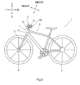
- (Embodiment 3) 5 is a left side view showing a schematic configuration of a bicycle T having a bicycle stem 100.
- the bicycle T according to this embodiment is, for example, a two-wheeled vehicle.
- the bicycle T has a front wheel 4, a rear wheel 5, a body frame 6, and a steering mechanism 7.
- the configurations of the front wheel 4, the rear wheel 5, and the body frame 6 are the same as those of conventional bicycles, so detailed explanations will be omitted.
- the same reference numerals will be used to designate the same components as those in the first and second embodiments, and explanations will be omitted.
- the torque sensor 30 is located behind the steering column 3. Therefore, the second stem 120 is connected to the steering column 3 so as to extend rearward.
- the first stem 110 is located axially outward of the steering column 3 and extends in a direction intersecting the axis P of the steering column 3 when viewed in the left-right direction.
- the first stem 110 is spaced apart from the second stem 120 in the axial direction of the steering column 3, i.e., in the X-axis direction.
- the movement restriction portion 130 has a restriction pin 131, a cylindrical elastic member 132, and a retaining member 133.
- the restriction pin 131 penetrates the first stem 110 in the X-axis direction, and one end side is fixed to the second stem 120. The other end side of the restriction pin 131 protrudes upward from the first stem 110.
- the elastic member 132 is made of a material that is elastically deformable in the radial direction. The elastic member 132 is arranged so as to cover the portion of the restriction pin 131 that penetrates the first stem 110. That is, the restriction pin 131 and the elastic member 132 penetrate the first stem 110 in the X-axis direction.
- the movement restricting unit 130 functions as an X-axis rotation restricting unit.
- the predetermined angle means an amount of movement that reduces the performance or measurement accuracy of the torque sensor 30 when the first stem 110 and the second stem 120 rotate relatively around the X-axis.
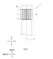
- the torque sensor 30 is positioned so that it overlaps at least a portion of the anchor 75 when looking at the bicycle stem 100 in the front-to-rear direction.
- first stem 110 is spaced apart from the second stem 120 in the X-axis direction. This makes it easier for the first stem 110 and the second stem 120 to be displaced relative to each other by torque input around the X-axis. Therefore, the torque sensor 30 can more easily detect the torque input to the first stem 110 and the second stem 120.
- the X-axis is an axis parallel to the axis P of the steering column.
- the X-axis may extend in the up-down direction, the front-rear direction, or the left-right direction. This makes it possible to detect various torques input to the handlebars or steering column using a torque sensor that can easily detect torque around the X-axis. Therefore, by positioning the torque sensor with respect to the stem in accordance with the bicycle usage scene, the torque sensor can detect torque taking into account the usage scene. This makes it possible to increase the signal-to-noise ratio of the torque signal detected by the torque sensor, improving the accuracy of torque detection by the torque sensor.
- the torque sensor 30 is located in the front-rear direction relative to the steering column connection part 21, 121.
- the torque sensor may be located in the left-right direction relative to the steering column connection part.
- the torque sensor may be positioned so that at least a portion of it overlaps with the steering column connection part when the bicycle stem is viewed in the left-right direction.
- the torque sensor may also be positioned so that a portion of it overlaps with the second stem when the bicycle stem is viewed in the front-to-rear direction.
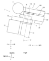
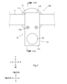
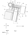
- Figures 9 and 10 are schematic diagrams showing a state in which a portion of the torque sensor 30 is positioned so that it overlaps with the second stem 220, 320 when the bicycle stem 200, 300 is viewed in the front-to-rear direction. The entire torque sensor 30 does not have to overlap with the second stem 220, 320 when the bicycle stem 200, 300 is viewed in the front-to-rear direction.
- the reference symbol 210 denotes the first stem.
- the steering assist motor 77 is located in front of the steering column 3.
- the steering assist motor may be located anywhere in relation to the steering column as long as it is located near the steering column, such as behind, to the left, or to the right of the steering column.
- the bicycle stem 100 has a movement restricting section 130.
- the movement restricting section may have the function of an X-axis rotation restricting section without having the function of an X-axis movement restricting section.
- the movement restricting section may have the function of an X-axis movement restricting section without having the function of an X-axis rotation restricting section.
- the movement restricting section may have a configuration other than that shown in the third embodiment, as long as it can perform the function of at least one of an X-axis movement restricting section or an X-axis rotation restricting section.
Landscapes
- Engineering & Computer Science (AREA)
- Mechanical Engineering (AREA)
- Steering Devices For Bicycles And Motorcycles (AREA)
- Force Measurement Appropriate To Specific Purposes (AREA)
Abstract
Selon l'invention, un capteur de couple 30 d'une potence de bicyclette 1 présente une configuration dans laquelle, lorsque le même couple est entré autour d'axes X, Y et Z qui sont orthogonaux entre eux, et dans laquelle la déformation est plus facilement provoquée par le couple autour de l'axe X que par le couple autour de l'axe Y ou le couple autour de l'axe Z. La potence de bicyclette 1 comprend : une première potence 10 qui comprend une section de raccordement de guidon 11 raccordée à un guidon 2, et une première section de raccordement de capteur de couple 12 raccordée au capteur de couple 30 ; et une seconde potence 20 qui comprend une section de raccordement de colonne de direction 21 raccordée à une colonne de direction 3, et une seconde section de raccordement de capteur de couple 22 raccordée au capteur de couple 30. La première potence 10 et la seconde potence 20 sont conçues de telle sorte que la section de raccordement de guidon 11 est située plus vers l'avant que la colonne de direction 3, et sont également conçues de telle sorte que la déformation est moins susceptible de se produire dans celles-ci que dans le capteur de couple 30 lorsque le même couple est entré autour de l'axe X.
Priority Applications (2)
| Application Number | Priority Date | Filing Date | Title |
|---|---|---|---|
| CN202480063974.6A CN121969548A (zh) | 2023-10-06 | 2024-10-07 | 自行车把立和设置有其的自行车 |
| TW113138157A TWI907097B (zh) | 2023-10-06 | 2024-10-07 | 自行車用桿及具備其之自行車 |
Applications Claiming Priority (2)
| Application Number | Priority Date | Filing Date | Title |
|---|---|---|---|
| PCT/JP2023/036641 WO2025074644A1 (fr) | 2023-10-06 | 2023-10-06 | Potence de bicyclette et bicyclette la comprenant |
| JPPCT/JP2023/036641 | 2023-10-06 |
Publications (1)
| Publication Number | Publication Date |
|---|---|
| WO2025075190A1 true WO2025075190A1 (fr) | 2025-04-10 |
Family
ID=95282990
Family Applications (2)
| Application Number | Title | Priority Date | Filing Date |
|---|---|---|---|
| PCT/JP2023/036641 Pending WO2025074644A1 (fr) | 2023-10-06 | 2023-10-06 | Potence de bicyclette et bicyclette la comprenant |
| PCT/JP2024/035778 Pending WO2025075190A1 (fr) | 2023-10-06 | 2024-10-07 | Potence de bicyclette et bicyclette la comprenant |
Family Applications Before (1)
| Application Number | Title | Priority Date | Filing Date |
|---|---|---|---|
| PCT/JP2023/036641 Pending WO2025074644A1 (fr) | 2023-10-06 | 2023-10-06 | Potence de bicyclette et bicyclette la comprenant |
Country Status (3)
| Country | Link |
|---|---|
| CN (1) | CN121969548A (fr) |
| TW (1) | TWI907097B (fr) |
| WO (2) | WO2025074644A1 (fr) |
Citations (3)
| Publication number | Priority date | Publication date | Assignee | Title |
|---|---|---|---|---|
| JP2006193142A (ja) * | 2005-01-12 | 2006-07-27 | Shimano Inc | 自転車用ステム |
| WO2017200095A1 (fr) * | 2016-05-19 | 2017-11-23 | ヤマハ発動機株式会社 | Véhicule à selle ayant un guidon |
| US20210396614A1 (en) * | 2020-06-23 | 2021-12-23 | Tien Hsin Industries Co., Ltd. | Bicycle power meter |
Family Cites Families (3)
| Publication number | Priority date | Publication date | Assignee | Title |
|---|---|---|---|---|
| JPH0733061A (ja) * | 1993-07-23 | 1995-02-03 | Marui:Kk | 自転車用ハンドルステムの固定構造 |
| US5782479A (en) * | 1996-06-21 | 1998-07-21 | Schwinn Cycling & Fitness Inc. | Steering mechanism safety system |
| KR20080002572U (ko) * | 2008-06-23 | 2008-07-11 | 김형욱 | 길이 변화가 가능한 자전거 스템 |
-
2023
- 2023-10-06 WO PCT/JP2023/036641 patent/WO2025074644A1/fr active Pending
-
2024
- 2024-10-07 CN CN202480063974.6A patent/CN121969548A/zh active Pending
- 2024-10-07 WO PCT/JP2024/035778 patent/WO2025075190A1/fr active Pending
- 2024-10-07 TW TW113138157A patent/TWI907097B/zh active
Patent Citations (3)
| Publication number | Priority date | Publication date | Assignee | Title |
|---|---|---|---|---|
| JP2006193142A (ja) * | 2005-01-12 | 2006-07-27 | Shimano Inc | 自転車用ステム |
| WO2017200095A1 (fr) * | 2016-05-19 | 2017-11-23 | ヤマハ発動機株式会社 | Véhicule à selle ayant un guidon |
| US20210396614A1 (en) * | 2020-06-23 | 2021-12-23 | Tien Hsin Industries Co., Ltd. | Bicycle power meter |
Also Published As
| Publication number | Publication date |
|---|---|
| WO2025074644A1 (fr) | 2025-04-10 |
| TWI907097B (zh) | 2025-12-01 |
| TW202528186A (zh) | 2025-07-16 |
| CN121969548A (zh) | 2026-05-01 |
Similar Documents
| Publication | Publication Date | Title |
|---|---|---|
| US10137961B2 (en) | Bicycle drive unit | |
| US9027691B2 (en) | Driving unit and electric assist bicycle | |
| US20170219066A1 (en) | Bicycle driving device | |
| US20170217537A1 (en) | Bicycle driving device | |
| US20170137086A1 (en) | Bicycle drive unit | |
| US10167053B2 (en) | Bicycle drive unit | |
| US20060175124A1 (en) | Support structure of motor-driven steering assist apparatus | |
| US10137959B2 (en) | Electric bicycle drive assembly with torque detection | |
| CN105164010A (zh) | 电动辅助自行车 | |
| JP6926167B2 (ja) | 駆動ユニットおよび電動補助自転車 | |
| CN104245477A (zh) | 电动动力转向装置 | |
| CN108238206A (zh) | 自行车用驱动单元及具备该驱动单元的自行车用驱动系统 | |
| CN103998331A (zh) | 驱动单元以及电动助力自行车 | |
| EP3069975B1 (fr) | Ensemble capteur et unité d'entraînement pour bicyclette et bicyclette | |
| JP7054812B2 (ja) | 電動アシスト自転車および駆動ユニット | |
| JP2020531336A (ja) | 車両のホイールハブ用のホイールハブトランスミッションユニット、ホイールハブ、および補助駆動される車両 | |
| JP6254865B2 (ja) | センサ収容体 | |
| TWI907097B (zh) | 自行車用桿及具備其之自行車 | |
| JP2021105442A (ja) | 人力駆動車用のクラッチ機構および人力駆動車用のクラッチシステム | |
| WO2025074645A1 (fr) | Unité moteur d'assistance de direction pour bicyclette, et bicyclette la comprenant | |
| TW202400463A (zh) | 電動助力自行車的動力模組 | |
| WO2022172346A1 (fr) | Ensemble guidon et véhicule de type à enfourcher | |
| JP7743302B2 (ja) | 人力駆動車用の検出装置、および、人力駆動車用の検出システム | |
| US20240166294A1 (en) | Shaft member for human-powered vehicle, hub for human-powered vehicle, wheel axle for human-powered vehicle, and detection device for human-powered vehicle | |
| JP6519831B2 (ja) | モータ駆動ユニット及び電動アシスト自転車 |
Legal Events
| Date | Code | Title | Description |
|---|---|---|---|
| 121 | Ep: the epo has been informed by wipo that ep was designated in this application |
Ref document number: 24874789 Country of ref document: EP Kind code of ref document: A1 |
|
| ENP | Entry into the national phase |
Ref document number: 2025550390 Country of ref document: JP Kind code of ref document: A |
|
| WWE | Wipo information: entry into national phase |
Ref document number: 2025550390 Country of ref document: JP |