WO2025088872A1 - Dispositif de télémétrie - Google Patents
Dispositif de télémétrie Download PDFInfo
- Publication number
- WO2025088872A1 WO2025088872A1 PCT/JP2024/028030 JP2024028030W WO2025088872A1 WO 2025088872 A1 WO2025088872 A1 WO 2025088872A1 JP 2024028030 W JP2024028030 W JP 2024028030W WO 2025088872 A1 WO2025088872 A1 WO 2025088872A1
- Authority
- WO
- WIPO (PCT)
- Prior art keywords
- wavelength
- laser light
- light
- interference
- measuring device
- Prior art date
- Legal status (The legal status is an assumption and is not a legal conclusion. Google has not performed a legal analysis and makes no representation as to the accuracy of the status listed.)
- Pending
Links
Images





Classifications
-
- G—PHYSICS
- G01—MEASURING; TESTING
- G01B—MEASURING LENGTH, THICKNESS OR SIMILAR LINEAR DIMENSIONS; MEASURING ANGLES; MEASURING AREAS; MEASURING IRREGULARITIES OF SURFACES OR CONTOURS
- G01B9/00—Measuring instruments characterised by the use of optical techniques
- G01B9/02—Interferometers
- G01B9/02055—Reduction or prevention of errors; Testing; Calibration
Definitions
- This disclosure relates to a distance measuring device.
- Optical interference using laser light is widely used as a means of obtaining information indicating the distance and/or shape of an object without contact.
- LiDAR Light Detection and Ranging
- FMCW Frequency Modulated Continuous Wave Radar
- OCT optical coherence tomography
- OCT optical coherence tomography
- measurements using a Michelson interferometer with a single-wavelength laser are one method of measuring distance differences on the order of nanometers.
- Optical measurements with nanometer accuracy are capable of non-contact and highly accurate measurements, but have the problem that the measurement range is limited to half the wavelength (sub-micrometer units). For this reason, there are cases where it is difficult to measure samples that have both nanometer-scale structures and structures on the scale of several tens of micrometers.
- Multi-wavelength interference which is optical interference using two or more single-wavelength laser beams, is expected to be a solution to this problem.
- Multi-wavelength interference can eliminate the trade-off between measurement range and measurement accuracy, which has traditionally been an issue, and can simultaneously achieve a long measurement range and high measurement accuracy.
- Patent Documents 1 and 2 it is said that by combining the results of optical interference of laser light with different wavelengths, it is possible to eliminate the trade-off between measurement range and measurement accuracy, which has been a problem in the past, and achieve a long measurement range and high measurement accuracy.
- the calculated distance information is affected by the wavelength of the laser light fluctuating over time. Specifically, this causes a decrease in measurement accuracy and a decrease in the stability of the measurement results over long periods of time.
- the present disclosure provides a distance measuring device that can suppress deterioration of measurement accuracy and long-term stability.
- a distance measuring device includes a light source unit that emits a first laser light and a reference laser light, a reference interference system that detects a first interference light generated by interfering with the first laser light and a second interference light generated by interfering with the reference laser light and outputs a first signal, a measurement interference system that receives a first reflected light generated by reflection of the first laser light by an object and outputs a second signal, and a signal processing system that generates wavelength information regarding the wavelength of the first laser light based on the first signal and calculates a distance from the distance measuring device to the object based on the wavelength information and the second signal.
- the optical path of the first laser light and the optical path of the reference laser light are arranged so that the first laser light and the reference laser light do not interfere with each other.
- This disclosure makes it possible to suppress deterioration of measurement accuracy and long-term stability.
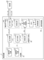
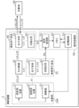
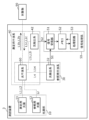
- FIG. 1 is a block diagram showing a configuration of a distance measuring device according to the first embodiment.
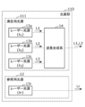
- FIG. 2 is a block diagram showing a configuration of a light source unit of the distance measuring device according to the first embodiment.
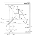
- FIG. 3 is a diagram showing a specific configuration of the measurement interference system of the distance measuring device according to the first embodiment.
- FIG. 4 is a diagram showing a specific configuration of the reference interference system of the distance measuring device according to the first embodiment.
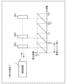
- FIG. 5 is a diagram for explaining the first principle of measurement using a single-wavelength laser light by the distance measuring device according to the first embodiment.
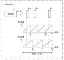
- FIG. 6 is a diagram for explaining the second principle of measurement using a plurality of single-wavelength laser beams by the distance measuring device according to the first embodiment.
- FIG. 1 is a block diagram showing a configuration of a distance measuring device according to the first embodiment.
- FIG. 2 is a block diagram showing a configuration of a light source unit of the distance measuring device according to the first embodiment.
- FIG. 3 is
- FIG. 7 is a diagram showing the measurement range and measurement accuracy of two measurements by the distance measuring device according to the first embodiment.
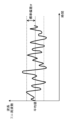
- FIG. 8 is a diagram for explaining the stability of the wavelength and frequency of a single-wavelength laser beam.
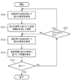
- FIG. 9 is a flowchart showing the operation of the distance measuring device according to the first embodiment.
- FIG. 10 is a diagram showing the relationship between the update frequency of the wavelength information and the calculation frequency of the distance.
- FIG. 11 is a block diagram showing a configuration of a distance measuring device according to the second embodiment.
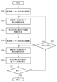
- FIG. 12 is a flowchart showing the operation of the distance measuring device according to the second embodiment.
- FIG. 13 is a block diagram showing a configuration of a distance measuring device according to the third embodiment.
- FIG. 14 is a block diagram showing a configuration of a light source unit of a distance measuring device according to the first modification of the embodiment.
- FIG. 15 is a block diagram showing a configuration of a distance measuring device according to the second modification of the embodiment.
- Measurement accuracy refers to the degree of accuracy when measuring distance. In other words, measurement accuracy is a measure of how accurately distance information can be obtained. Therefore, it can be said that the higher the measurement accuracy, the more accurate the measurement.
- the “measurement range” refers to the range in the distance direction in which unique distance information can be obtained.
- the measurement range refers to the range in which distance measurement (distance measurement) is possible.
- both the measurement accuracy and the measurement range are expressed in the same dimension as the distance.
- the units of the measurement accuracy and the measurement range are both expressed in nanometers (nm), micrometers ( ⁇ m), millimeters (mm), etc. Therefore, “high measurement accuracy” is synonymous with “short measurement accuracy” expressed in the dimension of distance. “low measurement accuracy” is synonymous with “long measurement accuracy” expressed in the dimension of distance.
- measurement accuracy may be simply referred to as “accuracy”.
- Measurement range may be simply referred to as "range”.
- a distance measurement within the measurement range is called “absolute distance measurement.”
- a distance measurement with an accuracy of 10 nm and a measurement range of 1 mm is an absolute distance measurement that can distinguish a difference of 10 nm within a range of 1 mm.
- Long-term stability means that there is little time fluctuation from the start to the end of the measurement, allowing measurements to be made with consistent accuracy. For example, if the wavelength of the laser light fluctuates over time, long-term stability decreases. When long-term stability decreases, problems such as limitations on the measurement time can occur.
- the distance measuring device includes a light source unit that emits a first laser light and a reference laser light, a reference interference system that detects a first interference light generated by interfering with the first laser light and a second interference light generated by interfering with the reference laser light and outputs a first signal, a measurement interference system that receives a first reflected light generated by reflection of the first laser light by an object and outputs a second signal, and a signal processing system that generates wavelength information regarding the wavelength of the first laser light based on the first signal and calculates the distance from the distance measuring device to the object based on the wavelength information and the second signal.
- the optical path of the first laser light and the optical path of the reference laser light are arranged so that the first laser light and the reference laser light do not interfere with each other.
- the actual wavelength value of the laser light used in the measurement can be obtained from the wavelength information.
- Wavelength fluctuations can be fed back into distance calculations, preventing any deterioration in measurement accuracy and long-term stability.
- the distance measuring device is the distance measuring device according to the first aspect, and in the distance measuring device according to the second aspect, the light source unit may further emit a second laser light having a wavelength different from that of the first laser light, and the measurement interference system may further receive as input a second reflected light generated by the second laser light being reflected by the object.
- MMI multiwavelength interferometry
- the reference interference system may detect the interference light generated by interfering with the second laser light and the interference light generated by interfering with the reference laser light, and output a third signal.
- the signal processing system may generate second wavelength information regarding the wavelength of the second laser light based on the third signal, and calculate the distance from the distance measuring device to the object based on first wavelength information, which is wavelength information regarding the wavelength of the first laser light, the second wavelength information, and the second signal.
- the second wavelength information when using the second laser light. For example, if the fluctuation in the wavelength of the first laser light is smaller than the fluctuation in the wavelength of the second laser light, high measurement accuracy can be ensured based on the interference results of the first laser light. Therefore, even if the second wavelength information regarding the wavelength of the second laser light is not obtained, high measurement accuracy and a large measurement range can be achieved.
- the distance measuring device is the distance measuring device according to the second aspect, and in the distance measuring device according to the third aspect, the wavelength of the reference laser light may be shorter than the wavelength of the first laser light.
- the distance measuring device may be the distance measuring device according to the second or third aspect, and in the distance measuring device according to the fourth aspect, the measurement interference system may include a first optical interference system that causes the first laser light and the first reflected light to interfere with each other, and emits a third interference light generated by the interference between the first laser light and the first reflected light, and causes the second laser light and the second reflected light to interfere with each other, and emits a fourth interference light generated by the interference between the second laser light and the second reflected light, and a first optical detection system that detects the third interference light and the fourth interference light and outputs the second signal.
- a first optical interference system that causes the first laser light and the first reflected light to interfere with each other, and emits a third interference light generated by the interference between the first laser light and the first reflected light, and causes the second laser light and the second reflected light to interfere with each other, and emits a fourth interference light generated by the interference between the second laser light and the second reflected light
- a first optical detection system that detects
- the measurement laser light and the reference laser light are subjected to heterodyne interference, a beat signal is detected by a photodetector, and the result of the measurement using the measurement laser light is corrected based on the result.
- a condition for heterodyne interference the difference in wavelength between the two laser lights must be small, so the wavelength options for the measurement laser light are limited by the reference laser light.
- HeNe lasers are examples of lasers with stabilized wavelengths that are commonly used.
- the wavelength of the laser light for length measurement is limited to wavelengths around 633 nm, which is the wavelength of the HeNe laser light.
- Optical elements suitable for wavelengths around 633 nm are expensive, and there is a problem that measurement is difficult when the object is a visible lens with an AR coating.
- MWI uses lasers with multiple different wavelengths as the laser light for length measurement, it is necessary to prepare the same number of light sources for the reference laser light.
- the distance measuring device uses homodyne interference, so the absolute difference between the wavelengths of the two laser lights used for measurement can be larger than when heterodyne interference is used, and the wavelength selectivity of the two laser lights can be improved.
- a wavelength suitable for measuring the object can be selected, and as a result, the deterioration of the measurement accuracy and long-term stability of the object can be suppressed.
- only one light source for the reference laser light is required regardless of the number of wavelengths of the measurement laser light. Therefore, the configuration of the distance measuring device can be simplified, made smaller, and reduced in cost.
- the accuracy of measuring wavelengths is higher than with other methods, resulting in higher length measurement accuracy and long-term stability than with other methods.
- the distance measuring device is the distance measuring device according to the first aspect, and in the distance measuring device according to the fifth aspect, the light source unit may further emit a plurality of second laser lights, the wavelengths of the plurality of second laser lights may be different from each other, and the wavelength of each of the plurality of second laser lights may be different from the wavelength of the first laser light, and the measurement interference system may further receive a plurality of second reflected lights generated by the reflection of the plurality of second laser lights by the object.
- the distance measuring device is a distance measuring device according to any one of the first to fifth aspects, and may further include an optical splitter that splits the first laser light emitted from the light source unit into a first part and a second part, inputs the first part to the reference interference system, and inputs the second part to the measurement interference system.
- the distance measuring device is a distance measuring device according to any one of the first to sixth aspects, and in the distance measuring device according to the seventh aspect, the reference interference system may include a second optical interference system that causes the first laser light to interfere and emits the first interference light generated by the interference of the first laser light, and causes the reference laser light to interfere and emits the second interference light generated by the interference of the reference laser light, and a second optical detection system that detects the first interference light and the second interference light and outputs the first signal.
- the interference signal of the first laser light and the interference signal of the reference laser light can be obtained as the first signal with high accuracy. Therefore, the calculation accuracy of the wavelength based on the first signal can be improved.
- the absolute difference value of the wavelengths of the two laser lights used for measurement can be large, so the wavelength selectivity of the two laser lights can be improved. For example, a wavelength suitable for measuring the object can be selected, and as a result, the deterioration of the measurement accuracy and long-term stability of the object can be suppressed.
- the configuration of the distance measuring device can be simplified, made smaller, and reduced in cost.
- a more stable single-wavelength laser such as a HeNe laser, can be used, the accuracy of measuring the wavelength is higher than other methods, and as a result, the measurement accuracy and long-term stability are higher than other methods.
- the distance measuring device is the distance measuring device according to the seventh aspect, and in the distance measuring device according to the eighth aspect, the reference interference system may further include an optical path difference changing mechanism that changes the difference between the optical path length of the first laser light passing through the second optical interference system and the optical path length of the reference laser light passing through the second optical interference system.
- the optical path difference it is possible to cause a change in the intensity of each of the interference signals of the first laser light and the reference laser light.
- the wavelength of the first laser light can be calculated with high accuracy based on the change in intensity of the interference signal.
- changing the difference in optical path length is not essential.
- the interference signal of the first laser light and the interference signal of the reference laser light may each be monitored without changing the difference in optical path length.
- the spectral information of each of the first laser light and the reference laser light is calculated. Assuming that the spectral intensity of each of the first laser light and the reference laser light has Gaussian characteristics, the wavelength required for calculating the length measurement is the peak wavelength of each laser light.
- a distance measuring device is a distance measuring device according to any one of the first to eighth aspects, and in the distance measuring device according to the ninth aspect, the signal processing system may generate the wavelength information indicating the peak wavelength by calculating the peak wavelength of the first laser light based on the first signal.
- the distance measuring device is a distance measuring device according to any one of the second to fourth aspects, and in the distance measuring device according to the tenth aspect, the signal processing system may generate the wavelength information indicating the peak wavelength of the first laser light and the peak wavelength of the second laser light by calculating the peak wavelength of the first laser light and the peak wavelength of the second laser light based on the first signal.
- the distance measuring device is a distance measuring device according to any one of the first to tenth aspects, and in the distance measuring device according to the eleventh aspect, the signal processing system may update the wavelength information when a predetermined condition is satisfied.
- wavelength information can be updated at an appropriate time.
- a ranging device is a ranging device according to any one of the first to eleventh aspects, and in the ranging device according to the twelfth aspect, the signal processing system may include a memory for storing the generated wavelength information, the frequency at which the signal processing system generates the wavelength information may be less than the frequency at which the signal processing system calculates the distance, and the signal processing system may calculate the distance based on the wavelength information stored in the memory and the second signal.
- the frequency with which wavelength information is generated can be reduced.
- the computational cost required to generate wavelength information is generally higher than the computational cost required for length measurement. By reducing the frequency with which wavelength information is generated, the computational cost can be suppressed.
- the distance measuring device is the distance measuring device according to the twelfth aspect, and in the distance measuring device according to the thirteenth aspect, the signal processing system may generate the wavelength information and update the wavelength information stored in the memory when the fluctuation of the wavelength of the first laser light exceeds a threshold value.
- wavelength information can be updated when wavelength fluctuations occur that affect the distance calculation results.
- wavelength information can be updated at an effective and less wasteful timing.
- the distance measuring device is a distance measuring device according to any one of the first to thirteenth aspects, and in the distance measuring device according to the fourteenth aspect, the light source unit may include an adjustment unit that adjusts the wavelength of the first laser light based on the wavelength information.
- the distance measuring device is a distance measuring device according to any one of the first to fourteenth aspects, and in the distance measuring device according to the fifteenth aspect, the first laser light may be a laser light including a plurality of single modes.
- the distance measuring device is a distance measuring device according to any one of the first to fifteenth aspects, and in the distance measuring device according to the sixteenth aspect, the reference interferometer system and the measurement interferometer system may share an optical interferometer system.
- the distance measuring device is the distance measuring device according to the first aspect, and in the distance measuring device according to the seventeenth aspect, a third reflected light generated by the reference laser light being reflected by the object may be further input to the measurement interference system.
- each figure is a schematic diagram and is not necessarily an exact illustration. Therefore, for example, the scales of the figures do not necessarily match.
- the same reference numerals are used for substantially the same configurations, and duplicate explanations are omitted or simplified.
- ordinal numbers such as “first” and “second” do not refer to the number or order of components, unless otherwise specified, but are used for the purpose of avoiding confusion between and distinguishing between components of the same type.
- Fig. 1 is a block diagram showing the configuration of a distance measuring device 1 according to the present embodiment.
- the distance measuring device 1 shown in FIG. 1 is a device that measures the distance to an object 90.
- the distance measuring device 1 can obtain information indicating the surface shape of the object 90 by measuring the distance to each part of the object 90. Therefore, for example, the distance measuring device 1 can be used for visual inspection of products, etc.
- the distance measuring device 1 includes a light source unit 10, an optical splitter 20, a reference interferometer system 30, a measurement interferometer system 40, and a signal processing system 50.
- the distance measuring device 1 may also include a support unit that supports the object 90.
- the support unit may include a drive unit such as a motor or a piezoelectric element, and may be capable of changing the attitude and/or position of the object 90.
- the dotted line connecting the two blocks that make up the distance measuring device 1 represents the path of light. Also, the solid arrows connecting the two blocks that make up the distance measuring device 1 indicate the transmission path of the main signal and the transmission direction of the signal.
- the light source unit 10 emits a plurality of laser beams.
- the plurality of laser beams are single-wavelength laser beams having different peak wavelengths.
- the light source unit 10 emits a first laser beam, a second laser beam, and a reference laser beam.
- the light source unit 10 includes a measurement light source 11 and a reference light source 12.
- the measurement light source 11 emits laser light L1, which is an example of a first laser light.
- the measurement light source 11 also emits laser light L2, which is an example of a second laser light.
- the reference light source 12 emits reference laser light Lr. A more specific configuration of the light source unit 10 will be described later with reference to FIG. 2.
- Wavelength fluctuation is a parameter that indicates the amount of temporal fluctuation in wavelength. Wavelength fluctuation includes not only short-term fluctuation but also long-term drift. Drift means that the average value of short-term fluctuation shifts over time.
- the wavelength fluctuation of the reference laser light Lr is smaller than the wavelength fluctuation of the laser lights L1 and L2. Details of wavelength fluctuation will be explained later.
- the optical splitter 20 splits the laser light L1 emitted from the light source unit 10 into light L1r and light L1t and emits them.
- Light L1r is input to the reference interferometer system 30, and light L1t is input to the measurement interferometer system 40.
- the optical splitter 20 also emits the laser light L2 as light L2t without splitting it.
- the optical splitter 20 may split the laser light L2 into two beams and emit them. One of the two beams after splitting is input to the reference interferometer system 30, and the other beam, L2t, is input to the measurement interferometer system 40.
- the optical splitter 20 splits the intensity of the incident light and emits it in different directions.
- the optical splitter 20 is, for example, a half mirror, and its intensity split ratio is, for example, 1:1, but is not limited to this.
- the intensity of light L1r may be higher than the intensity of light L1t, and the intensity of light L1t may be higher than the intensity of light L1r.
- the wavelength of the light does not change when it is split by the optical splitter 20.
- the reference interference system 30 detects the light obtained by interfering the first laser light and the light obtained by interfering the reference laser light, and outputs a first signal S1 according to the detection result of the interfered light. Specifically, the light L1r emitted from the optical splitter 20 and the reference laser light Lr from the reference light source 12 are incident on the reference interference system 30. As shown in FIG. 1, the reference interference system 30 includes an optical interference system 31 and an optical detection system 32.
- the optical interference system 31 is an example of a second optical interference system, which causes light L1r to interfere and emits interference light L1ri, and causes reference laser light Lr to interfere and emit interference light Lri.
- the interference light L1ri is an example of a first interference light
- the interference light Lri is an example of a second interference light.
- the interference by the optical interference system 31 is homodyne interference.
- the optical detection system 32 is an example of a second optical detection system, and detects the interference light L1ri and Lri, and outputs a first signal S1.
- the first signal S1 is output to the signal processing system 50.
- the first signal S1 is used to calculate the wavelength of the light L1r, i.e., the wavelength of the light L1t.
- the measurement interferometer 40 receives a first reflected light generated when the light of the first laser light irradiated on the object 90 is reflected by the object 90, and outputs a second signal S2.
- the measurement interferometer 40 also receives a second reflected light generated when the light of the second laser light irradiated on the object 90 is reflected by the object 90.
- the measurement interferometer 40 receives the light L1t emitted from the optical splitter 20 and the reflected light L1c from the object 90.
- the measurement interferometer 40 also receives the light L2t emitted from the optical splitter 20 and the reflected light L2c from the object 90.
- the measurement interferometer 40 includes an optical interferometer 41 and an optical detection system 42.
- the optical interference system 41 is an example of a first optical interference system, which causes light L1t and reflected light L1c to interfere with each other, emitting a third interference light L1i generated by the interference between light L1t and reflected light L1c, and causes light L2t and reflected light L2c to interfere with each other, emitting a fourth interference light L2i generated by the interference between light L2t and reflected light L2c.
- the interference caused by the optical interference system 41 is homodyne interference.
- the optical detection system 42 is an example of a first optical detection system, which detects the third interference light L1i and the fourth interference light L2i, and outputs a second signal S2 according to the detection results of the third interference light L1i and the fourth interference light L2i.
- the second signal S2 is output to the signal processing system 50.
- the second signal S2 is used to calculate the distance from the distance measuring device 1 to the object 90.
- the signal processing system 50 generates wavelength information regarding the wavelength of the first laser light based on the first signal S1, and calculates the distance from the distance measuring device 1 to the object 90 based on the wavelength information and the second signal S2. As shown in FIG. 1, the signal processing system 50 includes a signal receiving unit 51, a memory 52, and a processing circuit 53.
- the signal receiving unit 51 acquires a first signal S1 from the reference interferometer 30 and acquires a second signal S2 from the measurement interferometer 40.
- the signal receiving unit 51 stores the acquired first signal S1 and second signal S2 in the memory 52.
- the memory 52 is a storage device such as a non-volatile memory and/or a volatile memory.
- the first signal S1 and the second signal S2 are stored in the memory 52.
- the memory 52 may also store programs and data for operating each component of the distance measuring device 1, as well as wavelength information and distance information obtained by signal processing.
- the processing circuit 53 is a circuit that processes signals output from the reference interferometer 30 and the measurement interferometer 40. Specifically, the processing circuit 53 calculates the peak wavelength of the first laser light based on the first signal S1, thereby generating wavelength information indicating the calculated peak wavelength. In this embodiment, the processing circuit 53 calculates the peak wavelength ⁇ 1 of the laser light L1 and the peak wavelength ⁇ 2 of the laser light L2 based on the first signal S1. The processing circuit 53 calculates the distance from the distance measuring device 1 to the object 90 based on the wavelength information stored in the memory 52 and the second signal S2. For example, the processing circuit 53 processes the second signal S2 output from the measurement interferometer 40 based on a predetermined algorithm, thereby acquiring the position of the object 90 as phase information. As a representative phase estimation algorithm, a 4-step phase-shifting algorithm or the like can be used. The processing circuit 53 can calculate the distance from the distance measuring device 1 to the object 90 based on the phase information.
- the processing circuit 53 calculates the distance within a short measurement range with high measurement accuracy based on the interference results for one wavelength.
- the processing circuit 53 calculates the distance within a long measurement range with low measurement accuracy based on the interference results for two wavelengths. The specific method of calculating the distance will be explained later.
- the processing circuit 53 is realized by an integrated circuit such as an LSI (Large Scale Integration).
- the processing circuit 53 may be realized by a dedicated hardware configuration and calculate the distance from the distance measuring device 1 to the object 90.
- the processing circuit 53 may include a processor and calculate the distance from the distance measuring device 1 to the object 90 by having the processor execute a program stored in the memory 52.
- the processing circuit 53 may be a programmable FPGA (Field Programmable Gate Array), or a reconfigurable processor in which the connections and settings of circuit cells in the LSI can be reconfigured.
- Fig. 2 is a block diagram showing the configuration of the light source unit 10 of the distance measuring device 1 according to this embodiment.
- the measurement light source 11 includes laser light sources 13a and 13b and a wavelength synthesis system 14.
- the reference light source 12 includes a laser light source 13r.
- the laser light source 13a emits a laser beam L1 having a wavelength ⁇ 1.
- the laser beam L1 is an example of a first laser beam, and is, for example, a single-wavelength laser beam.
- the wavelength ⁇ 1 is the peak wavelength of the laser beam L1.
- the laser light source 13b emits a laser light L2 having a wavelength ⁇ 2 .
- the laser light L2 is an example of a second laser light, and is, for example, a single-wavelength laser light.
- the wavelength ⁇ 2 is a peak wavelength of the laser light L2, and is a wavelength different from the wavelength ⁇ 1 . The shorter the absolute difference between the wavelengths ⁇ 1 and ⁇ 2 (
- the laser light source 13r emits a reference laser light Lr having a wavelength ⁇ r.
- the reference laser light Lr is an example of a reference laser light, and is, for example, a single-wavelength laser light.
- the wavelength ⁇ r is a peak wavelength of the reference laser light Lr, and is a wavelength different from both the wavelengths ⁇ 1 and ⁇ 2 .
- the wavelength ⁇ r is shorter than the wavelength ⁇ 1 .
- the laser light sources 13a and 13b are, for example, semiconductor laser elements.
- a distributed feedback (DFB) laser light source which is characterized by high wavelength and frequency stability, can be used for the laser light sources 13a and 13b.
- the laser light source 13r is, for example, a HeNe laser light source.
- the wavelength of the reference laser light Lr emitted by the laser light source 13r is approximately 633 nm.
- a HeNe laser light source is a light source that emits light with less wavelength fluctuation compared to semiconductor laser elements, i.e., has high wavelength stability over time.
- the wavelength combining system 14 combines the laser beams L1 and L2 emitted from the two laser light sources 13a and 13b.
- the wavelength combining system 14 is, for example, a DWDM (Dense Wavelength Division Multiplexing) element or a holographic optical element.
- Fig. 3 is a diagram showing a specific configuration of the measurement interferometry system 40 of the distance measuring device 1 according to this embodiment.
- the optical interference system 41 is an optical system that uses Michelson interference. As shown in FIG. 3, the optical interference system 41 includes a beam splitter 43 and a mirror 44.
- Beam splitter 43 is an optical element that splits the intensity of the incident light into multiple beams and emits each of the multiple beams in different directions.
- Beam splitter 43 is, for example, a half mirror, and splits the incident light into transmitted light and reflected light, each of which has the same intensity. Note that the intensity ratio between the transmitted light and reflected light does not have to be 1:1.
- the beam splitter 43 splits the light L1t, which is the laser light L1 from the light source unit 10 and split by the optical splitter 20, into two lights L1a and L1b.
- the beam splitter 43 also splits the light L2t, which is the laser light L2 from the light source unit 10, into two lights L2a and L2b.
- the light L1a and the light L2a are reflected lights reflected by the beam splitter 43, and are emitted toward the mirror 44.
- the light L1b and L2b are transmitted lights that have passed through the beam splitter 43, and are emitted toward the object 90.
- the mirror 44 is an example of an optical element that reflects the light L1a and L2a from the beam splitter 43 and makes them enter the beam splitter 43. Specifically, the mirror 44 specularly reflects the incident light. The higher the reflectivity, the less light loss there is, and the higher the detection accuracy can be. Both the light L1a and L2a that enter the mirror 44 are reflected by the mirror 44 and re-enter the beam splitter 43. At least a portion of each of the light L1a and L2a that are reflected by the mirror 44 and re-enter the beam splitter 43 passes through the beam splitter 43.
- the light beams L1b and L2b irradiated to the object 90 are reflected by the object 90 and re-enter the beam splitter 43 as reflected light beams L1c and L2c. At least a portion of each of the reflected light beams L1c and L2c re-entering the beam splitter 43 is reflected by the beam splitter 43. In this case, interference occurs between the reflected light beams L1c and L2c and the light beams L1a and L2a.
- the interference light generated by the homodyne interference between the reflected light beams L1c and L1a is shown as interference light beam L1i.
- the interference light generated by the homodyne interference between the reflected light beams L2c and L2a is shown as interference light beam L2i.
- the interference light beams L1i and L2i are output to the optical detection system 42.
- the positions of the mirror 44 and the object 90 can be interchanged. That is, when the light from the light source unit 10 is split into transmitted light and reflected light by the beam splitter 43, the transmitted light may be irradiated onto the mirror 44, and the reflected light may be irradiated onto the object 90.
- optical interference system 41 is not limited to an optical system that uses Michelson interference.
- the optical interference system 41 may be an optical system that uses Fizeau interference or Mach-Zehnder interference, etc.
- the optical detection system 42 includes a dichroic mirror 45, a mirror 46, and optical detectors 47 and 48.
- the dichroic mirror 45 is an example of a wavelength separation element that separates incident light into light of wavelength ⁇ 1 and light of wavelength ⁇ 2. Specifically, the dichroic mirror 45 separates the light incident on the light detection system 42 from the beam splitter 43 into wavelengths. In this embodiment, the dichroic mirror 45 outputs the light of wavelength ⁇ 1 toward the photodetector 47 and outputs the light of wavelength ⁇ 2 toward the photodetector 48. In this embodiment, a mirror 46 is provided for adjusting the optical path.
- the mirror 46 specularly reflects the light of wavelength ⁇ 2 separated by the dichroic mirror 45, causing it to be incident on the photodetector 48. Note that the mirror 46 may not be provided, and the photodetector 48 may be disposed at the position of the mirror 46. Alternatively, the mirror 46 may be provided for the purpose of adjusting the optical path of the light of wavelength ⁇ 1 .
- the photodetectors 47 and 48 each include a photoelectric conversion element that generates an electric signal according to the intensity of the incident light.
- the photodetector 47 has sensitivity to at least the wavelength ⁇ 1 , and outputs an interference signal S21 having a signal level according to the intensity of the light by photoelectrically converting the light of the wavelength ⁇ 1 to the signal processing system 50 as a second signal S2.
- the interference signal S21 is a signal obtained by detecting interference light L1i between a part of the laser light L1 and reflected light L1c from the object 90.
- the photodetector 48 has sensitivity to at least the wavelength ⁇ 2 , and photoelectrically converts the light of the wavelength ⁇ 2 to output an interference signal S22 having a signal level according to the intensity of the light as a second signal S2 to the signal processing system 50.
- the interference signal S22 is a signal obtained by detecting interference light L2i between at least a part of the laser light L2 and reflected light L2c from the object 90.
- the configuration of the optical detection system 42 is not limited to the above example, so long as it is possible to receive light for each wavelength.
- the light traveling from the beam splitter 43 to the optical detection system 42 may be split into two beams in terms of intensity, and each of the two beams may then be passed through a filter having a transmission band for a specific wavelength component.
- the filter used may be, for example, a bandpass filter, but may also be a lowpass filter, highpass filter, etc.
- the measurement interferometer 40 does not have to be an optical system that uses homodyne interference.
- the measurement interferometer 40 may be an optical system that uses heterodyne interference.
- the measurement interferometer 40 does not need to include a dichroic mirror 45 that splits the light into wavelengths, and the number of photodetectors may be one.
- Fig. 4 is a diagram showing a specific configuration of the reference interferometer 30 of the distance measuring device 1 according to this embodiment.
- the optical interference system 31 is an optical system that uses a Sagnac-type Michelson interference system.
- Light L1r which is a part of the laser light L1 split by the optical splitter 20, and reference laser light Lr are incident on the optical interference system 31 at different incident positions.
- the optical interference system 31 includes a beam splitter 33, mirrors 34 and 35, and a movable mirror 36.
- Beam splitter 33 is an optical element that splits the intensity of the incident light into multiple beams and emits each of the multiple beams in different directions. Beam splitter 33 is, for example, a half mirror, and splits the incident light into transmitted light and reflected light, each of which has the same intensity. Note that the intensity ratio between the transmitted light and reflected light does not have to be 1:1.
- the beam splitter 33 splits the light L1r into two lights L1ra and L1rb.
- the beam splitter 33 also splits the reference laser light Lr into two lights Lra and Lrb.
- the light L1ra and the light Lra are reflected lights reflected by the beam splitter 33, and are emitted toward the mirror 35.
- the light L1rb and the light Lrb are transmitted lights that have passed through the beam splitter 33, and are emitted toward the mirror 34.
- Mirror 34 reflects light L1rb and Lrb toward movable mirror 36.
- Mirror 35 reflects light L1ra and Lra toward movable mirror 36.
- the movable mirror 36 has two reflective surfaces 36a and 36b.
- the reflective surface 36a reflects the light Lra and L1ra, respectively.
- the light Lra and L1ra reflected by the reflective surface 36a are reflected by the mirror 35 and then enter the beam splitter 33, at least a portion of which is transmitted.
- the reflective surface 36b reflects the light Lrb and L1rb, respectively.
- the light Lrb and L1rb reflected by the reflective surface 36b are reflected by the mirror 34 and then enter the beam splitter 33, at least a portion of which is reflected.
- the movable mirror 36 can change the positions of the reflecting surfaces 36a and 36b.
- a movable stage is provided that movably supports at least one of the reflecting surfaces 36a and 36b.
- the optical path length of the light traveling through the optical interference system 31 changes.
- the movable mirror 36 is an example of an optical path difference changing mechanism that changes the difference between the optical path length of the light L1r passing through the optical interference system 31 and the optical path length of the reference laser light Lr passing through the optical interference system 31. By adjusting the optical path difference, the interference light Lri and L1ri change.
- the optical path difference changing mechanism provided in the optical interference system 31 is not limited to the movable mirror 36 as long as it can change the optical path length.
- the optical interference system 31 may be provided with an electro-optical modulator (EOM) arranged on the optical path as the optical path difference changing mechanism.
- EOM electro-optical modulator
- the optical detection system 32 includes optical detectors 37 and 38.
- Each of the optical detectors 37 and 38 includes a photoelectric conversion element that generates an electrical signal according to the intensity of the incident light.
- the photodetector 37 has sensitivity to at least the wavelength ⁇ 1 , and performs photoelectric conversion on the light of the wavelength ⁇ 1 to output an interference signal S11 having a signal level according to the intensity of the light as a first signal S1 to the signal processing system 50.
- the interference signal S11 is a signal obtained by detecting interference light L1ri generated by homodyne interference of light L1r, which is a part of the laser light L1.
- the photodetector 38 is sensitive to at least the wavelength ⁇ r, and outputs an interference signal S12 having a signal level according to the intensity of the light by photoelectric conversion of the light of wavelength ⁇ r to the signal processing system 50 as a first signal S1.
- the interference signal S12 is a signal obtained by detecting the interference light Lri generated by homodyne interference of the reference laser light Lr.
- the distance measuring device 1 performs distance measurement based on multi-wavelength interference (MWI) using multiple laser beams.
- MWI multi-wavelength interference
- MWI combines the results of interference between multiple single-wavelength laser beams with different wavelengths, eliminating the trade-off between measurement range and measurement accuracy, and achieving a long measurement range and high measurement accuracy.
- the principle of multi-wavelength interference is explained below.
- a single-wavelength laser light is split by a beam splitter 43 and irradiated onto a mirror 44 that functions as a reference surface and an object 90, the distance of which is to be measured.
- the reflected light from the mirror 44 and the object 90 is made to interfere with each other by the beam splitter 43.
- the intensity P PD of the signal output from the photodetector 47 is expressed by the following equation (1).
- L - L x -L y .
- L x is the distance from the beam splitter 43 to the reflecting surface of the mirror 44.
- L y is the distance from the beam splitter 43 to the object 90.
- ⁇ k is the wavelength of the single-wavelength laser light.
- k is calculated based on the first signal S1 output from the reference interference system 30.
- both L x and ⁇ k are known values to the processing circuit 53. Therefore, the processing circuit 53 can calculate the distance L y from the beam splitter 43 to the object 90 based on the signal intensity P PD .
- the first measurement has a problem in that the measurement range is relatively short. Below, the relationship between the position of the object 90 and the measurement range is explained using Figure 5.
- FIG. 5 is a diagram for explaining the first principle of measurement using single-wavelength laser light by distance measuring device 1 according to this embodiment.
- objects 90a, 90b, and 90c respectively represent object 90 shown in FIG. 1 and FIG. 3, which are located at different positions. When there is no need to distinguish between the positions, they will be described as "object 90".
- the processing circuit 53 can calculate the distance from the distance measuring device 1 to the object 90 within a predetermined length measurement range. As can be seen from formula (1), when the wavelength of the single-wavelength laser light is ⁇ 1 , the length measurement range is half the wavelength ( ⁇ 1 /2).
- the absolute distance from the distance measuring device 1 to the object 90 cannot be calculated.
- objects 90a, 90b, and 90c are all calculated to be the same distance.
- the wavelength of the single-wavelength laser light is, for example, a wavelength in the near-infrared light band or the visible light band.
- the near-infrared light band is a wavelength band of approximately 700 nm or more and approximately 2500 nm or less.
- the visible light band is a wavelength band of approximately 380 nm or more and approximately 780 nm or less.
- the measurement range in the first measurement is approximately 190 nm or more and approximately 1250 nm or less. In other words, the measurement range in the first measurement is on the order of several hundred nanometers to several micrometers. In this way, the measurement range of the first measurement is relatively narrower than that of the second measurement described below.
- the light that has interfered in the beam splitter 43 is split into wavelengths by the dichroic mirror 45 and detected by two photodetectors 47 and 48.
- each of the photodetectors 47 and 48 outputs a signal corresponding to the result of the homodyne optical interference for the corresponding wavelength.
- the processing circuit 53 can calculate the distance from the distance measuring device 1 to the object 90 based on the two signals.
- the measurement range is increased by combining the two signals.
- the relationship between the position of the object 90 and the measurement range is explained using Figure 6.
- FIG. 6 is a diagram for explaining the second measurement principle using two single-wavelength laser beams by the distance measuring device 1 according to this embodiment.
- objects 90a, 90b, and 90c respectively represent the object 90 shown in FIG. 1 and FIG. 3, which is located at different positions. When there is no need to distinguish between the positions, they will be described as "object 90".
- FIG. 6 two graphs are shown in which the horizontal axis represents the distance to the object 90 using a specified position as a reference point, and the vertical axis represents the distance calculated by the processing circuit 53.
- the upper graph is the same as the graph shown in FIG. 5, and represents the distance calculated based on the signal obtained from one of the two photodetectors 47 and 48.
- the lower graph represents the distance calculated based on the signal obtained from the other of the two photodetectors 47 and 48.
- the measurement range is ⁇ 1 /2 or ⁇ 2 /2, respectively, so the order of the measurement range is almost the same as in the first measurement.
- the measurement range can be extended by combining the two graphs.
- the distances calculated for the objects 90a, 90b, and 90c corresponding to the upper graph are almost the same.
- the distances calculated for the objects 90a, 90b, and 90c corresponding to the lower graph are different. Therefore, by combining the two calculation results, it is possible to calculate a distance with a measurement range longer than both ⁇ 1 /2 and ⁇ 2 /2.
- the processing circuit 53 calculates the absolute distance from the distance measuring device 1 to the object 90 by combining the first distance obtained by the first measurement and the second distance obtained by the second measurement.
- the measurement range in the second measurement is half the beat wavelength of the two single-wavelength laser beams.
- the beat wavelength ⁇ 12 is expressed by the following formula (2).
- Optical interference due to this beat wavelength ⁇ 12 enables distance measurement in a measurement range equivalent to half the beat wavelength ⁇ 12.
- the beat wavelength ⁇ 12 is 2.4 mm and the measurement range is 1.2 mm.
- the measurement range in the case of single wavelength interference is about 775 nm, which is on the order of nanometers, the measurement range of MWI is expanded to the order of millimeters.
- the measurement accuracy depends on the wavelength of the single-wavelength laser light used for the measurement. Specifically, the shorter the wavelength of the single-wavelength laser light, the higher the measurement accuracy (i.e., the smaller the distance dimension), and the longer the wavelength of the single-wavelength laser light, the lower the measurement accuracy (i.e., the longer the distance dimension).
- the measurement accuracy depends on the beat wavelength. Specifically, the shorter the beat wavelength, the higher the measurement accuracy (i.e., the smaller the distance dimension), and the longer the beat wavelength, the lower the measurement accuracy (i.e., the longer the distance dimension).
- the second measurement Since the beat wavelength is longer than the wavelength of the single-wavelength laser light, the second measurement has lower measurement accuracy than the first measurement. That is, the measurement accuracy of the second measurement is deteriorated due to the beat wavelength ⁇ 12. In this way, the trade-off between the measurement range and the measurement accuracy is not yet resolved by only using the second measurement.
- MWI achieves both a long measurement range and high measurement accuracy at the same time by combining the first and second measurements.
- first measurement which has a short measurement range but high measurement accuracy
- second measurement which has a long measurement range but low measurement accuracy
- FIG. 7 is a diagram showing the measurement range and measurement accuracy of two measurements by the distance measuring device 1 of this embodiment.
- the measurement accuracy in the second measurement is Am
- the measurement range in the second measurement is Rm.
- the measurement accuracy in the first measurement is As
- the measurement range in the first measurement is Rs. Both the measurement range and measurement accuracy are expressed in terms of distance, so they can be compared.
- Rm>Rs and Am>As hold. Furthermore, in this embodiment, Am ⁇ Rs holds. That is, the measurement accuracy Am of the second measurement is equal to or less than the measurement range Rs of the first measurement. This allows a unique combination of the first measurement and the second measurement, making it possible to measure distances with a measurement accuracy higher than the measurement accuracy of the second measurement.
- the wavelength and frequency of the laser light are adjusted by a control unit (not shown) so that they are maintained at predetermined set values. Specifically, the amount of current supplied to the laser light source and/or the temperature of the laser light source are adjusted to keep the wavelength constant.
- the set wavelength of the light source unit 10 is controlled to be fixed during the measurement period.
- Figure 8 is a diagram for explaining the stability of the wavelength of single-wavelength laser light.
- the horizontal axis represents time
- the vertical axis represents the wavelength or frequency of single-wavelength laser light.
- Figure 8 shows short-term wavelength fluctuations.
- the wavelength fluctuation is represented, for example, by the standard deviation ⁇ shown in FIG. 8.
- the standard deviation ⁇ can be calculated statistically for the average or median wavelength of the laser light within a finite time period. Note that the wavelength fluctuation may be represented in frequency units rather than wavelength units, or in other units that are correlated with the wavelength.
- the wavelength stability is expressed as a value that has a negative correlation with the fluctuation of the wavelength of the laser light over time. Specifically, the smaller the fluctuation, the higher the wavelength stability, and the larger the fluctuation, the lower the wavelength stability.
- the laser light source 13a that emits the laser light L1 can be, but is not limited to, a DFB laser light source that has the characteristic of high wavelength (frequency) stability, or a light source device that combines a gas cell absorption line and a semiconductor laser as a reference frequency.
- DFB lasers have high wavelength stability, if the operating time is long (e.g., 30 minutes or more), the wavelength drifts, resulting in poor measurement accuracy. In other words, even if a laser light source with a stable wavelength is used as the light source for emitting the laser light L1, it is not possible to suppress the deterioration of measurement accuracy and long-term stability from a long-term perspective. Note that long-term wavelength fluctuations can be regarded as the amount of drift in the peak wavelength.
- the processing circuit 53 calculates the wavelength ⁇ 1 based on the first signal S1 output from the reference interference system 30. Specifically, the processing circuit 53 uses the interference signals S11 and S12 to compare the number of waves of each interference signal, or to perform spectrum comparison by Fourier transform, to calculate the wavelength ⁇ 1 ( see, for example, Patent Document 3). The processing circuit 53 then uses the calculated wavelength ⁇ 1 to calculate the distance from the distance measuring device 1 to the object 90. As a result, even if the wavelength of the laser light L1 fluctuates, the wavelength ⁇ 1 at the time of measurement can be obtained with high accuracy, thereby improving the measurement accuracy and long-term stability of the distance measuring device 1.
- the processing circuit 53 calculates the wavelength ⁇ 1 of the laser light L1 used in the first measurement which requires high accuracy
- the processing circuit 53 may calculate the wavelength ⁇ 2 of the laser light L2.
- the laser light L2 is split into a first light and a second light by the optical splitter 20, the first light is input to the reference interference system 30, and an interference signal is obtained by homodyne interference of the second light.
- the wavelength ⁇ 1 calculated based on the first signal S1 from the reference interference system 30 is used, so that the wavelength ⁇ 1 used in the actual measurement can be used for calculating the distance. This makes it possible to improve the measurement accuracy and long-term stability of the distance measuring device 1.
- the phase of each wavelength is calculated based on the signals from each of the two photodetectors 47 and 48 shown in FIG. 3, and the difference is obtained as the phase of the beat wavelength ⁇ 12.
- the wave number N of the wavelength ⁇ 1 of the laser light L1 is determined from the quotient component obtained by dividing the rough distance calculated from the phase of the beat wavelength ⁇ 12 by the wavelength ⁇ 1 of the laser light L1, which has a small frequency fluctuation.
- the value calculated based on the first signal S1 is used as the wavelength ⁇ 1 of the laser light L1.
- the phase ⁇ of a single wavelength is calculated based on a signal from one of the two photodetectors 47 and 48 shown in FIG. 3 (here, the photodetector 47). Based on the above results, the absolute distance x is calculated using the following formula (3).
- the main cause of the fluctuation component of the calculated distance x is ⁇ , which is due to the fluctuation of the wavelength of the first single-wavelength laser light. Therefore, by using the value obtained by calculation as the wavelength ⁇ 1 of the laser light L1 used in the first measurement, the calculation accuracy of the absolute distance can be improved.
- the optimal combination of wavelengths is that the laser light L1 used in the first measurement has the smallest wavelength fluctuation, that is, the laser with the highest wavelength stability.
- Fig. 9 is a flowchart showing the operation of the distance measuring device 1 according to this embodiment.
- the distance measuring device 1 acquires a first signal S1 using the reference interference system 30 (S10).
- the light source unit 10 outputs laser light L1 and/or L2 and reference laser light Lr.
- the laser light L1 is split into light L1r and light L1t by the optical splitter 20.
- the reference interference system 30 detects each of the light L1r and the reference laser light Lr by causing them to interfere with each other through homodyne interference, and outputs interference signals S11 and S12 to the signal processing system 50 as the first signal S1.
- the signal processing system 50 generates wavelength information based on the first signal S1, and updates the wavelength information stored in the memory 52 (S11).
- the wavelength information is information indicating the wavelength ⁇ 1 of the laser light L1.
- the generated wavelength information is stored in the memory 52.
- the distance measuring device 1 then obtains a second signal S2 using the measurement interferometry system 40 (S12). Specifically, the measurement interferometry system 40 receives the light L1t and light L2t (laser light L2), and the reflected light L1c and L2c generated by the reflection of each of these lights by the object 90. The measurement interferometry system 40 detects the light L1t and the reflected light L1c by causing them to interfere with each other through homodyne interference, and detects the light L2t and the reflected light L2c by causing them to interfere with each other through homodyne interference, thereby outputting interference signals S21 and S22 to the signal processing system 50 as the second signal S2.
- the measurement interferometry system 40 receives the light L1t and light L2t (laser light L2), and the reflected light L1c and L2c generated by the reflection of each of these lights by the object 90.
- the measurement interferometry system 40 detects the light L1t and
- the signal processing system 50 calculates the distance based on the wavelength information stored in the memory 52 and the second signal S2 (S13). By using the wavelength ⁇ 1 indicated by the wavelength information, the accuracy of the length measurement can be improved.
- the signal processing system 50 determines whether or not to update the wavelength information (S15).
- the wavelength information is updated, for example, at a predetermined timing. If the wavelength information is to be updated (Yes in S15), the ranging device 1 acquires the first signal (S10) and updates the wavelength information (S11).
- the distance measuring device 1 acquires a second signal (S12) and calculates the distance (S13).
- the wavelength information stored in the memory 52 is used to calculate the distance.
- FIG. 10 shows the relationship between the frequency of updating wavelength information and the frequency of calculating distance.
- the arrows represent the flow of time
- the triangles represent the timing at which the corresponding processing is performed.
- the laser light L1 used to obtain the second signal S2 in step S12 is emitted at a different timing from the laser light L1 used to generate the wavelength information stored in the memory 52.
- a DFB laser light source or the like with little short-term wavelength fluctuation as the laser light source 13a that emits the laser light L1
- by updating the wavelength information stored in the memory 52 at a predetermined timing it is possible to suppress a decrease in the measurement accuracy even if long-term fluctuations in the wavelength ⁇ 1 of the laser light L1, i.e., drift of the wavelength ⁇ 1 occurs. This makes it possible to suppress a decrease in the measurement accuracy and long-term stability of the distance measuring device 1.
- the wavelength information stored in the memory 52 may be updated after a certain wavelength deviation occurs from the wavelength at the start of measurement.
- the signal processing system 50 may generate wavelength information and update the wavelength information stored in the memory 52 when the fluctuation of the wavelength ⁇ 1 of the first laser light L1 exceeds a threshold value. That is, the processing circuit 53 may periodically calculate the wavelength ⁇ 1 , and update the wavelength information stored in the memory 52 when the difference between the calculated value of the wavelength ⁇ 1 and the initial value at the start of distance measurement or the wavelength set in the laser light source, that is, the fluctuation of the wavelength ⁇ 1 , exceeds a threshold value.
- the wavelength information may not be updated, and an error may be output using a display unit and/or a voice output unit, etc., to warn the user of a measurement error.
- the frequency of updating the wavelength information and the frequency of calculating the distance may be the same.
- a laser light source with large wavelength fluctuations can be used as the laser light source 13a. Since an inexpensive laser light source can be used, the cost of the distance measuring device 1 can be reduced.
- the wavelength information may be updated only once before the measurement starts. In other words, the process of step S15 does not need to be executed.
- wavelength information is not limited to being updated once before measurement begins. Wavelength information may be updated when a specified condition is met. One specified condition is, for example, that a certain period of time has passed. Specifically, wavelength information may be updated periodically, such as once a day, once a week, or once a month. Periods when no measurement is performed may be treated as if there is no wavelength fluctuation.
- one of the predetermined conditions may be that the wavelength drift is outside a threshold range.
- the wavelength of the laser light may be indirectly measured to confirm that the wavelength drift is within a threshold range (e.g., 1 nm/8 hours), and the wavelength information may be updated when the wavelength drift falls outside the threshold range.
- Indirect methods for monitoring the wavelength include measuring changes in temperature and/or air pressure around the laser light source, or measuring the temperature of the laser light source itself.
- the distance measuring device 1 uses homodyne interference rather than heterodyne interference.
- Heterodyne interference requires that the wavelength interval between the two lights be small, whereas homodyne interference has no wavelength limitations. Therefore, the distance measuring device 1 has the advantage that the wavelength selectivity of each of the laser lights L1 and L2 used for measurement is high.
- the laser light irradiated to the object 90 must be outside the visible light band.
- the wavelength selectivity is high, the wavelength of the measurement laser light can be set to the communication wavelength band, and the reference laser light can be set to a short wavelength that improves the measurement accuracy.
- the distance measuring device 1 when heterodyne interference is used, it becomes necessary to use the same number of measurement laser light sources and reference laser light sources, which increases the size and cost of the device.
- the distance measuring device 1 according to this embodiment requires only one laser light source 13r as the reference laser light source, which makes it possible to simplify the configuration of the distance measuring device, make it more compact, and reduce costs.
- a more stable single-wavelength laser such as a HeNe laser, can be used, the accuracy of measuring the wavelength is higher than with other methods, which results in higher measurement accuracy and long-term stability than with other methods.
- the distance measuring device differs from the first embodiment mainly in that the light source unit includes an adjustment unit that adjusts the wavelength of the laser light.
- the light source unit includes an adjustment unit that adjusts the wavelength of the laser light.
- FIG. 11 is a block diagram showing the configuration of a distance measuring device 2 according to this embodiment. As shown in FIG. 11, the distance measuring device 2 differs from the distance measuring device 1 shown in FIG. 1 in that it includes a light source unit 10A instead of the light source unit 10.
- the light source unit 10A includes an adjustment unit 15 in addition to the configuration of the light source unit 10.
- the adjustment unit 15 adjusts the wavelength of the first laser light based on the wavelength information.
- the adjustment unit 15 adjusts the wavelength ⁇ 1 of the laser light L1, for example, by controlling the operating temperature and/or the applied current of the laser light source 13a of the measurement light source 11.
- the adjustment unit 15 adjusts the value of the fluctuating (drifting) wavelength ⁇ 1 so as to return it to the wavelength ⁇ 1 at the start of measurement, which is the initial state.
- the adjustment unit 15 acquires the wavelength information generated by the processing circuit 53, and adjusts the wavelength ⁇ 1 when the wavelength ⁇ 1 indicated by the acquired wavelength information exceeds a threshold value.
- FIG. 12 is a flowchart showing the operation of the distance measuring device 2 according to this embodiment.
- the adjustment unit 15 sets the wavelength of the laser light for measurement (S20). Specifically, the adjustment unit 15 sets the wavelength ⁇ 1 of the laser light L1 and the wavelength ⁇ 2 of the laser light L2 to predetermined values as initial values. The initial values of the wavelengths ⁇ 1 and ⁇ 2 are determined based on, for example, the measurement accuracy required for measuring the distance of the object 90 (for example, inspecting the surface shape), etc.
- the distance measuring device 2 obtains a first signal S1 using the reference interference system 30 (S21).
- the signal processing system 50 generates wavelength information based on the first signal S1 (S22).
- the wavelength information is information indicating the wavelength ⁇ 1 of the laser light L1.
- the generated wavelength information is stored in the memory 52. Note that steps S21 and S22 are the same processes as steps S10 and S11 shown in FIG. 9.
- the adjustment unit 15 adjusts the wavelength ⁇ 1 of the laser light L1 (S23). Specifically, the adjustment unit 15 adjusts the temperature and/or applied current of the laser light source 13a based on the wavelength ⁇ 1 indicated by the wavelength information stored in the memory 52 so that the value of the wavelength ⁇ 1 becomes the initial value of the wavelength ⁇ 1 of the laser light L1. Note that, if the difference between the wavelength ⁇ 1 indicated by the wavelength information stored in the memory 52 and the initial value of the wavelength ⁇ 1 of the laser light L1 is less than a threshold, the adjustment process (S23) may be omitted.
- the distance measuring device 2 obtains the second signal S2 using the measurement interferometer 40 (S24).
- the signal processing system 50 calculates the distance based on the wavelength information stored in the memory 52 and the second signal S2 (S25). By using the wavelength ⁇ 1 indicated by the wavelength information, the measurement accuracy can be improved. Note that steps S24 and S25 are the same processes as steps S12 and S13 shown in FIG. 9.
- the signal processing system 50 judges whether or not to adjust the wavelength ⁇ 1 (S27).
- the adjustment of the wavelength ⁇ 1 is performed, for example, at a predetermined timing. If the adjustment of the wavelength ⁇ 1 is to be performed (Yes in S27), the distance measurement device 2 acquires a first signal (S21), generates wavelength information (S22), and adjusts the wavelength ⁇ 1 (S23).
- the distance measuring device 2 obtains the second signal (S24) and calculates the distance (S25).
- the wavelength information stored in the memory 52 is used in the distance calculation.
- the adjustment unit 15 may further adjust the wavelength ⁇ 2 of the laser light L2, thereby further improving the measurement accuracy.
- Whether or not to adjust the wavelength ⁇ 1 may be determined based on the amount of drift, which is the fluctuation of the wavelength ⁇ 1 , in the same manner as whether or not to update the wavelength information in the first embodiment. Also, if the measurement is for a short period of time, the adjustment of the wavelength ⁇ 1 may be performed only once before the start of the measurement. In other words, the process of step S27 may not be performed.
- the distance measuring device differs from embodiment 1 mainly in that the reference interferometer and the measurement interferometer share an optical interferometer.
- the following explanation focuses on the differences from embodiment 1, and the explanation of the commonalities will be omitted or simplified.
- FIG. 13 is a block diagram showing the configuration of a distance measuring device 3 according to this embodiment.
- the reference interferometer system 30 and the measurement interferometer system 40 share a single optical interferometer system 60.
- the distance measuring device 3 does not need to include an optical splitter 20.
- the number of components included in the distance measuring device 3 can be reduced, and therefore the distance measuring device 3 can be made smaller and lighter.
- the operation of the distance measuring device 3 is the same as that of the distance measuring device 1.
- the light source unit 10 may be provided with an adjustment unit 15, similar to the distance measuring device 2 according to embodiment 2.
- Modifications 1 and 2 described below are mainly different from the respective embodiments in the configuration of the light source unit. Since the configuration other than the light source unit is the same as the respective embodiments, the description will be omitted or simplified.
- FIG. 14 is a block diagram showing the configuration of the light source unit 110 of the distance measuring device according to the first modified example.
- the light source unit 110 includes a measurement light source 111 and a reference light source 12.
- the measurement light source 111 includes three laser light sources 13a, 13b, and 13c, and a wavelength synthesis system 14.
- the laser light sources 13a and 13b are the same as those in the embodiment, and therefore a description thereof will be omitted.
- the laser light source 13c is, for example, a semiconductor laser element, and emits a laser light of a predetermined single wavelength when a current is supplied.
- the laser light source 13c is an example of a third laser light source, and emits a laser light L3 having a wavelength ⁇ 3.
- the wavelength ⁇ 3 is an example of a third wavelength
- the laser light L3 is an example of one of a plurality of second laser lights.
- the wavelength ⁇ 3 is a wavelength different from both the wavelength ⁇ 1 and the wavelength ⁇ 2. In this embodiment, the wavelength ⁇ 3 is longer than both the wavelength ⁇ 1 and the wavelength ⁇ 2.
- the difference between the wavelength ⁇ 3 and the wavelength ⁇ 1 may be 10 times or more the difference between the wavelength ⁇ 2 and the wavelength ⁇ 1.
- the difference in the beat wavelength can be made large.
- the measurement range and the measurement accuracy can be set in stages, so that the absolute distance can be measured with high accuracy.
- the wavelength combining system 14 combines the laser beams L1, L2, and L3 emitted from the three laser light sources 13a, 13b, and 13c.
- the wavelength combining system 14 is, for example, a DWDM element or a holographic optical element.
- the configuration of the distance measuring device according to this modification is the same as that of the distance measuring device 1 shown in Fig. 1, the distance measuring device 2 shown in Fig. 11, or the distance measuring device 3 shown in Fig. 13.
- the optical detection system 42 of the measurement interference system 40 includes an optical detector for detecting light of wavelength ⁇ 3 .
- the optical detection system 42 may detect beat light by heterodyne interference.
- the second measurement can be performed based on at least one of the three combinations. Specifically, the second measurement can be performed with a measurement accuracy and a measurement range according to at least one of the beat wavelength ⁇ 12 due to the interference between the laser beam L1 of wavelength ⁇ 1 and the laser beam L2 of wavelength ⁇ 2 , the beat wavelength ⁇ 13 due to the interference between the laser beam L1 of wavelength ⁇ 1 and the laser beam L3 of wavelength ⁇ 3 , and the beat wavelength ⁇ 23 due to the interference between the laser beam L3 of wavelength ⁇ 3 and the laser beam L2 of wavelength ⁇ 2.
- the beat wavelength ⁇ 12 is expressed by the formula (2), and the beat wavelengths ⁇ 13 and ⁇ 23 are expressed by the following formulas (4) and (5), respectively.
- the beat wavelengths ⁇ 12 and ⁇ 13 can be made to differ greatly from each other.
- ⁇ 1 , ⁇ 2 , and ⁇ 3 are set to 1550 nm, 1551 nm, and 1600 nm, respectively.
- the beat wavelength ⁇ 12 is approximately 2.4 mm
- the beat wavelength ⁇ 13 is approximately 50 ⁇ m. Since ⁇ 1 ⁇ ⁇ 2 , the beat wavelength ⁇ 13 is approximately equal to the beat wavelength ⁇ 23 .
- the processing circuitry 53 performs a second measurement using two of the beat wavelengths ⁇ 12 , ⁇ 13 , and ⁇ 23 , and combines the result of the second measurement with the result of the first measurement to calculate the distance from the distance measuring device to the object 90. Specifically, the processing circuitry 53 calculates the absolute distance from the distance measuring device to the object 90 by combining the first distance obtained by the first measurement and the two second distances obtained by the second measurement.
- the processing circuit 53 uses a beat wavelength based on a laser light having the smallest fluctuation in wavelength and frequency among all the single-wavelength laser lights emitted by the light source unit 110.
- the wavelength fluctuation of the laser light L1 is the smallest
- beat wavelengths ⁇ 13 and ⁇ 12 are used.
- the processing circuit 53 uses the interference result of the laser light having the smallest wavelength fluctuation among all the single-wavelength laser lights emitted by the light source unit 110.
- the absolute distance x is expressed by the following equation (6).
- a and B are the wave numbers of the beat wavelength ⁇ 12 and the wavelength ⁇ 1 , respectively, contained within the absolute distance x i from the probe to the first portion of the object 90.
- ⁇ i corresponds to the positions of the first portion, the second portion, and the third portion of the object 90, and represents the phase of the interference result based on the wavelength ⁇ 1 obtained in the first measurement.
- equation (6) corresponds to equation (3) expanded to three wavelengths. Note that the first portion, the second portion, and the third portion are different portions of the surface of the object 90.
- the second measurement is performed with the combination that results in the longest beat wavelength.
- the distance calculated in this second measurement is an example of a third distance calculated with a third measurement accuracy within a third measurement range. Note that the third measurement accuracy is lower than the second measurement accuracy and the first measurement accuracy.
- the third measurement range is longer than the second measurement range and the first measurement range. Simply put, the second measurement is performed with the combination that results in the longest measurement range.
- the processing circuit 53 identifies the phase of the beat wavelength ⁇ 12 based on the combination of the wavelengths ⁇ 1 and ⁇ 2 .
- the processing circuit 53 counts the wave number A of the beat wavelength ⁇ 13 of the next second measurement based on the identified phase of the beat wavelength ⁇ 12 .
- the wave number A of the beat wavelength ⁇ 13 is calculated using the components of the quotient obtained by dividing the distance calculated based on the beat wavelength ⁇ 12 by the beat wavelength ⁇ 13 .
- the processing circuit 53 identifies the phase of the beat wavelength ⁇ 13 based on the combination of the wavelengths ⁇ 1 and ⁇ 3 as the next second measurement.
- the processing circuit 53 counts the wave number B of the wavelength ⁇ 1 of the first measurement based on the identified phase of the beat wavelength ⁇ 13 .
- the wave number B of the wavelength ⁇ 1 is calculated by dividing the distance calculated based on the beat wavelength ⁇ 13 by the wavelength ⁇ 1 .
- the processing circuitry 53 determines the phase ⁇ 1 of the wavelength ⁇ 1 as the first measurement.
- the processing circuitry 53 can calculate the absolute distance x i based on the wave numbers A and B and the phase ⁇ 1 of the wavelength ⁇ 1 using the above-mentioned equation (6).
- the measurement range can be further expanded.
- the absolute distance may be calculated using methods other than those described above.
- the excess fraction method may be used, which calculates the absolute distance by matching the phase combination of all wavelengths of the laser used.
- FIG. 15 is a block diagram showing the configuration of a distance measuring device 201 according to the second modification.
- the distance measuring device 201 is different from the distance measuring device 1 shown in FIG. 1 in that it includes a light source unit 210 instead of the light source unit 10.
- the light source unit 210 includes a laser light source 13a and a laser light source 13r.
- the light source unit 210 may also include a wavelength synthesis system 14.
- the laser light source 13r is a light source that emits a reference laser light Lr.
- the reference laser light Lr is input not only to the reference interference system 30 but also to the measurement interference system 40.
- the reference laser light Lr is also used as a second laser light for measurement.
- the reference laser light Lr is split by the optical splitter 20 into light L2r (Lr) that is input to the reference interference system 30 and light L2t that is input to the measurement interference system 40. Therefore, the reflected light L2c of the reference laser light Lr that is reflected by the object 90 is input to the measurement interference system 40.
- the light source unit 210 may include an adjustment unit 15, similar to the distance measuring device 2 according to embodiment 2.
- the processing circuit 53 calculates the absolute distance from the distance measuring device to the object 90, but this is not limiting. After calculating the first distance and the second distance, the processing circuit 53 may output these to another device. For example, the processing circuit 53 may transmit the first distance and the second distance to another computer, and have the other computer calculate the absolute distance. Alternatively, the processing circuit 53 may transmit the first distance and the second distance to a display and display them on the display, or may output them to a printer and print them on a medium such as paper. In this way, the first distance and the second distance can be presented to a user, etc., so that the user can calculate the absolute distance by hand. In this way, the processing circuit 53 does not need to calculate the absolute distance.
- the wavelength of at least one of the two single-wavelength laser lights may be changeable.
- the wavelength of the laser light with the larger wavelength fluctuation may be swept. This allows the combination of the two wavelengths to be changed, making it possible to achieve a measurement range and measurement accuracy suitable for the target object 90.
- the device can be made more compact than when three or more laser light sources are provided.
- one laser beam split from a single wavelength laser beam into two, and the other laser beam with a shifted frequency may be used as the two single wavelength laser beams.
- an acousto-optic modulator AOM can be used as a means for shifting the frequency.
- the first laser light emitted by the measurement light source 11 may be a laser light including multiple single modes.
- the first laser light may be an optical frequency comb laser light.
- An optical frequency comb laser light is a laser light whose spectrum is made up of discrete and equally spaced frequency lines.
- the wavelength fluctuation does not have to be the standard deviation ⁇ .
- the wavelength fluctuation may be 3 ⁇ .
- the wavelength fluctuation may be the variance ⁇ 2 of the frequency of the laser light within a finite time.
- the wavelength fluctuation may be the difference between the maximum value and the minimum value of the wavelength of the laser light within a finite time.
- the light source unit includes three or more laser light sources
- two of the laser light sources may emit single-wavelength laser light of the same wavelength.
- the frequency fluctuations of the two single-wavelength laser lights of the same wavelength may be the same.
- one of the two single-wavelength laser lights of the same wavelength may be used, and in the second measurement, the other of the two single-wavelength laser lights of the same wavelength may be used.
- the first single-wavelength laser light used in each of the first and second measurements may be laser light emitted from different laser light sources.
- the measurement accuracy Am of the second measurement may be greater than the measurement range Rs of the first measurement. If the difference between the measurement accuracy Am of the second measurement and the measurement range Rs of the first measurement is small, and Am>Rs, it becomes possible to measure the distance with substantially the same accuracy as when Am ⁇ Rs.
- the wavelength information may be information indicating the optical spectrum of the laser light, rather than the peak wavelength of the laser light.
- the general or specific aspects of the present disclosure may be realized as a system, an apparatus, a method, an integrated circuit, or a computer program.
- the present disclosure may be realized as a computer-readable non-transitory recording medium, such as an optical disk, a HDD, or a semiconductor memory, on which the computer program is stored.
- the present disclosure may also be realized as any combination of a system, an apparatus, a method, an integrated circuit, a computer program, and a recording medium.
- the present disclosure can be used as a distance measuring device that can suppress deterioration of measurement accuracy and long-term stability, and can be used, for example, in surface shape inspection devices.
- Adjustment unit 20 Optical splitter 30 Reference interference system 31, 41, 60 Optical interference system 32, 42 Optical detection system 33, 43 Beam splitter 34, 35, 44, 46 Mirror 36 Movable mirror 36a, 36b Reflecting surface 37, 38, 47, 48 Photodetector 40 Measurement interference system 45 Dichroic mirror 50 Signal processing system 51 Signal receiving unit 52 Memory 53 Processing circuit 90, 90a, 90b, 90c Object
Landscapes
- Physics & Mathematics (AREA)
- General Physics & Mathematics (AREA)
- Instruments For Measurement Of Length By Optical Means (AREA)
Abstract
Un dispositif de télémétrie selon la présente invention comprend une unité de source de lumière qui émet une première lumière laser et une lumière laser de référence, un système d'interférence de référence qui détecte une première lumière d'interférence générée en faisant interférer la première lumière laser et une seconde lumière d'interférence générée en faisant interférer la lumière laser de référence et délivre un premier signal, un système d'interférence de mesure qui reçoit une entrée de la première lumière réfléchie générée par la réflexion de la première lumière laser au niveau d'un objet et délivre un second signal, et un système de traitement de signal qui génère des informations de longueur d'onde concernant la longueur d'onde de la première lumière laser sur la base du premier signal et calcule la distance entre le dispositif de télémétrie et l'objet sur la base des informations de longueur d'onde et du second signal. Un trajet de lumière pour la première lumière laser et un trajet de lumière pour la lumière laser de référence sont disposés au niveau du système d'interférence de référence de telle sorte que la première lumière laser et la lumière laser de référence n'interfèrent pas l'une avec l'autre.
Applications Claiming Priority (2)
| Application Number | Priority Date | Filing Date | Title |
|---|---|---|---|
| JP2023-184003 | 2023-10-26 | ||
| JP2023184003 | 2023-10-26 |
Publications (1)
| Publication Number | Publication Date |
|---|---|
| WO2025088872A1 true WO2025088872A1 (fr) | 2025-05-01 |
Family
ID=95515485
Family Applications (1)
| Application Number | Title | Priority Date | Filing Date |
|---|---|---|---|
| PCT/JP2024/028030 Pending WO2025088872A1 (fr) | 2023-10-26 | 2024-08-06 | Dispositif de télémétrie |
Country Status (2)
| Country | Link |
|---|---|
| CN (1) | CN223565891U (fr) |
| WO (1) | WO2025088872A1 (fr) |
Citations (9)
| Publication number | Priority date | Publication date | Assignee | Title |
|---|---|---|---|---|
| JPH01137436U (fr) * | 1988-03-16 | 1989-09-20 | ||
| JPH0514867U (ja) | 1991-03-04 | 1993-02-26 | 横河電機株式会社 | 光波長計 |
| JPH05296849A (ja) * | 1992-04-21 | 1993-11-12 | Olympus Optical Co Ltd | 波長測定器 |
| JPH06117810A (ja) * | 1991-05-28 | 1994-04-28 | Yokogawa Electric Corp | 外乱補正機能付きアブソリュ−ト測長器 |
| JPH1090175A (ja) * | 1996-08-20 | 1998-04-10 | Zygo Corp | 測定経路内のガスの屈折率の変動を測定する装置及び方法 |
| JPH10215027A (ja) * | 1997-01-29 | 1998-08-11 | Mitsubishi Heavy Ind Ltd | 光周波数可変動作方法及び装置 |
| JP2001027513A (ja) * | 1999-07-14 | 2001-01-30 | Mitsutoyo Corp | 光波長測定方法及び装置 |
| JP2021148634A (ja) | 2020-03-19 | 2021-09-27 | 株式会社ミツトヨ | レーザ干渉装置 |
| CN115127662A (zh) * | 2022-07-14 | 2022-09-30 | 上海交通大学 | 基于连续波激光的脉冲激光干涉等效波长校准装置及方法 |
-
2024
- 2024-08-06 WO PCT/JP2024/028030 patent/WO2025088872A1/fr active Pending
- 2024-10-22 CN CN202422555192.4U patent/CN223565891U/zh active Active
Patent Citations (9)
| Publication number | Priority date | Publication date | Assignee | Title |
|---|---|---|---|---|
| JPH01137436U (fr) * | 1988-03-16 | 1989-09-20 | ||
| JPH0514867U (ja) | 1991-03-04 | 1993-02-26 | 横河電機株式会社 | 光波長計 |
| JPH06117810A (ja) * | 1991-05-28 | 1994-04-28 | Yokogawa Electric Corp | 外乱補正機能付きアブソリュ−ト測長器 |
| JPH05296849A (ja) * | 1992-04-21 | 1993-11-12 | Olympus Optical Co Ltd | 波長測定器 |
| JPH1090175A (ja) * | 1996-08-20 | 1998-04-10 | Zygo Corp | 測定経路内のガスの屈折率の変動を測定する装置及び方法 |
| JPH10215027A (ja) * | 1997-01-29 | 1998-08-11 | Mitsubishi Heavy Ind Ltd | 光周波数可変動作方法及び装置 |
| JP2001027513A (ja) * | 1999-07-14 | 2001-01-30 | Mitsutoyo Corp | 光波長測定方法及び装置 |
| JP2021148634A (ja) | 2020-03-19 | 2021-09-27 | 株式会社ミツトヨ | レーザ干渉装置 |
| CN115127662A (zh) * | 2022-07-14 | 2022-09-30 | 上海交通大学 | 基于连续波激光的脉冲激光干涉等效波长校准装置及方法 |
Also Published As
| Publication number | Publication date |
|---|---|
| CN223565891U (zh) | 2025-11-18 |
Similar Documents
| Publication | Publication Date | Title |
|---|---|---|
| JP2553276B2 (ja) | 3波長光学測定装置及び方法 | |
| US8363226B2 (en) | Optical interference measuring apparatus | |
| JP5778078B2 (ja) | 物体をモニタする干渉計システム | |
| JP5860614B2 (ja) | 周波数偏移干渉計及び選択的データ処理 | |
| US8873066B2 (en) | System and method for improved resolution, higher scan speeds and reduced processing time in scans involving swept-wavelength interferometry | |
| JP5511163B2 (ja) | 光波干渉による距離測定方法及び装置 | |
| JP5265918B2 (ja) | モード選択同調器からの光フィードバック | |
| US20150109622A1 (en) | Optical coherence tomography apparatus and optical coherence tomography method | |
| JP2015530598A (ja) | 雑音を低減した位置監視システム | |
| JP2017535955A (ja) | 光構成要素の高速較正およびプログラミング | |
| US20130088722A1 (en) | Measurement apparatus | |
| JP4871791B2 (ja) | 光コヒーレンストモグラフィ装置 | |
| JP2010261890A (ja) | 光波干渉計測装置 | |
| US20260016577A1 (en) | Distance measuring device | |
| CN104677296A (zh) | 一种光纤激光拍波和单波自混合干涉融合的位移测量系统 | |
| JP2017078677A (ja) | 距離測定装置及びその方法 | |
| CN223565891U (zh) | 测距装置 | |
| JP6503618B2 (ja) | 距離測定装置及びその方法 | |
| JP2010261776A (ja) | 光波干渉計測装置 | |
| CN115698626A (zh) | 用于测量物体的表面形貌的方法和系统 | |
| CN121986248A (en) | Distance measuring device | |
| US20210333148A1 (en) | Measurement apparatus and measurement method | |
| JPH0227202A (ja) | 光干渉測定装置 | |
| JP2024115237A (ja) | 光路長差計測装置および振動計測装置 | |
| WO2025154370A1 (fr) | Dispositif de télémétrie |
Legal Events
| Date | Code | Title | Description |
|---|---|---|---|
| 121 | Ep: the epo has been informed by wipo that ep was designated in this application |
Ref document number: 24881989 Country of ref document: EP Kind code of ref document: A1 |
|
| ENP | Entry into the national phase |
Ref document number: 2025552786 Country of ref document: JP Kind code of ref document: A |
|
| WWE | Wipo information: entry into national phase |
Ref document number: 2025552786 Country of ref document: JP |