WO2025100247A1 - Outil de support de feuille, appareil de nettoyage de matériau en feuille et procédé de nettoyage - Google Patents
Outil de support de feuille, appareil de nettoyage de matériau en feuille et procédé de nettoyage Download PDFInfo
- Publication number
- WO2025100247A1 WO2025100247A1 PCT/JP2024/037912 JP2024037912W WO2025100247A1 WO 2025100247 A1 WO2025100247 A1 WO 2025100247A1 JP 2024037912 W JP2024037912 W JP 2024037912W WO 2025100247 A1 WO2025100247 A1 WO 2025100247A1
- Authority
- WO
- WIPO (PCT)
- Prior art keywords
- bar
- support
- wire
- sheet
- sheet material
- Prior art date
- Legal status (The legal status is an assumption and is not a legal conclusion. Google has not performed a legal analysis and makes no representation as to the accuracy of the status listed.)
- Pending
Links
Images




Classifications
-
- B—PERFORMING OPERATIONS; TRANSPORTING
- B08—CLEANING
- B08B—CLEANING IN GENERAL; PREVENTION OF FOULING IN GENERAL
- B08B3/00—Cleaning by methods involving the use or presence of liquid or steam
- B08B3/04—Cleaning involving contact with liquid
-
- B—PERFORMING OPERATIONS; TRANSPORTING
- B08—CLEANING
- B08B—CLEANING IN GENERAL; PREVENTION OF FOULING IN GENERAL
- B08B3/00—Cleaning by methods involving the use or presence of liquid or steam
- B08B3/04—Cleaning involving contact with liquid
- B08B3/10—Cleaning involving contact with liquid with additional treatment of the liquid or of the object being cleaned, e.g. by heat, by electricity or by vibration
- B08B3/12—Cleaning involving contact with liquid with additional treatment of the liquid or of the object being cleaned, e.g. by heat, by electricity or by vibration by sonic or ultrasonic vibrations
Definitions
- the present invention relates to a sheet support device that supports sheet material, and a sheet material cleaning device and cleaning method.
- Patent Document 1 discloses a cleaning device used in the cleaning process that includes a cleaning tank (water tank) that contains a cleaning liquid, a support (holder) that holds the glass substrate, and a rocking mechanism that rocks the support.
- the cleaning tank of the cleaning device is provided with an ultrasonic generator at its bottom.
- a base that supports the oscillating mechanism is provided at the top of the cleaning tank.
- the support is frame- or box-shaped and configured to hold multiple glass substrates.
- a fixing part (10a) that is detachably fixed to the oscillating mechanism is provided at the top of the support.
- the oscillating mechanism includes a motor provided on the base of the cleaning tank and an oscillating part driven by the motor.
- the fixing part of the support is fixed to the oscillating part of the oscillating mechanism (see paragraphs 0006, 0007 and Figure 1 of the same document).
- a support holding multiple glass substrates is immersed in a cleaning solution in a cleaning tank, and the glass substrates held by the support are cleaned by vibrating the cleaning solution using an ultrasonic generator and by oscillating the support using an oscillating mechanism (see Figure 1 in the same document).
- ultra-thin glass sheets when cleaning an ultra-thin glass sheet with a thickness of 0.2 mm or less, it becomes difficult to prevent the glass sheet from deforming or breaking.
- ultra-thin glass sheets are prone to significant deformation and breakage when they are placed in a support, when the support containing the glass sheet is moved, or when the support is vibrated to perform cleaning.
- the present invention was made in consideration of the above circumstances, and its technical objective is to prevent damage to sheet materials during the cleaning process.
- the present invention is intended to solve the above problems, and provides a sheet support device comprising a frame and a support wire attached to the frame for supporting a sheet material, the frame comprising a first bar and a second bar opposed to each other, and a side bar connecting the first bar and the second bar, the support wire including a plurality of support wires stretched across the first bar and the second bar, and the support wire configured to be capable of supporting one main surface of the sheet material.
- one of the main surfaces of the sheet material is supported by a support wire that is stretched across the first and second bars of the frame, thereby preventing damage to the sheet material during cleaning.
- the support wire supports one of the main surfaces of the sheet material, no impact is applied to the edge of the sheet material even if the sheet support tool vibrates. This effectively prevents damage to the sheet material during the cleaning process.
- the sheet support device described in (1) above may further include a third bar that faces the first bar, and a plurality of restricting wires that are stretched across the first bar and the third bar and restrict the movement of the sheet, and may have a storage space between the support wires and the restricting wires into which the sheet material can be inserted and removed.
- the storage space formed between the restricting wire and the supporting wire allows the sheet material to be stored without being damaged.
- the restricting wire comes into contact with the sheet material when it is about to deform significantly, and by restricting the deformation of the sheet material, damage to the sheet material can be prevented.
- the distance from the axis of the first bar to the axis of the third bar may be shorter than the distance from the axis of the first bar to the axis of the second bar, and the restricting wire may be shorter than the supporting wire.
- the restraining wire does not get in the way when inserting or removing the sheet material into the storage space.
- the sheet support device may further include an end support that supports a lower end of the sheet material, and the end support may fix the support wire and the restricting wire in a state where the support wire and the restricting wire are spaced apart, and support the sheet material.
- the support wire and end supports can support the sheet material without damaging it.
- the end support member may include a support portion that supports the lower end portion of the sheet material, and the support portion may be made of an elastic material.
- the lower end of the sheet material is supported by the support portion configured as an elastic body, which effectively prevents damage to the lower end of the sheet material.
- the third bar may be attached to the side bar, and the third bar may be fixed to the side bar so that its position can be changed.
- the support wire and the restricting wire may be made of synthetic resin.
- This configuration prevents damage to the sheet material caused by contact between the support wire and the restraining wire.
- the support wire may be wound around the second bar.
- the support wire can be easily fixed to the second bar without using a fastener to fix the support wire to the second bar.
- the restraining wire may be wound around the third bar.
- the restricting wire can be easily fixed to the third bar without using a fastener for fixing the restricting wire to the third bar.
- the support wire and the restraining wire may be wound around the first bar.
- the support wire and the restraining wire can be easily fixed to the first bar without using a fastener to fix the wires to the first bar.
- the present invention is intended to solve the above problems, and is a sheet material cleaning device comprising the sheet support described in (2) or (3) above, and a cleaning tank capable of containing the sheet support and cleaning liquid, and further comprising a fourth bar fixed to the cleaning tank, the third bar being located on the front side of the frame, and the fourth bar being located on the rear side of the frame.
- the fourth bar can easily and securely fix the frame of the sheet support to the cleaning tank.
- the sheet material cleaning device according to the present invention is intended to solve the above problems, and is characterized by comprising a sheet support device according to any one of (1) to (10) above, and a cleaning tank capable of containing the sheet support device and cleaning liquid.
- the sheet support that supports the sheet material can be immersed in the cleaning liquid in the cleaning tank, allowing the sheet material to be cleaned without being damaged.
- the sheet material cleaning device described in (12) above may include a support device that supports the frame of the sheet support in an inclined position.
- the frame is supported in an inclined position by the support device, and the sheet material can be supported in an inclined position by the frame. This allows the sheet material to be washed in a stable position.
- the cleaning tank may be equipped with an ultrasonic generator that generates ultrasonic waves.
- the ultrasonic waves emitted from the ultrasonic generating unit vibrate the cleaning liquid, frame, and glass sheet, allowing the glass sheet to be cleaned effectively.
- the present invention is intended to solve the above problems, and is a method for cleaning a sheet material using the cleaning device described in any one of (11) to (14) above, characterized in that the sheet is a glass sheet having a thickness of 0.2 mm or less, and is cleaned with the cleaning liquid.
- the present invention makes it possible to prevent damage to sheet materials during the cleaning process.
- FIG. FIG. FIG. 4 is a cross-sectional view taken along the line IV-IV of FIG. 1.
- 2 is a cross-sectional view taken along the line VV of FIG. 1.
- 6 is a cross-sectional view taken along the line VI-VI of FIG. 1.
- 7 is a cross-sectional view taken along the line VII-VII of FIG. 1.
- FIG. 2 is a cross-sectional view showing an example of an end support.
- FIG. FIG. 11 is a cross-sectional view showing another example of the support device.
- FIG. FIG. 4 is a front cross-sectional view showing a dipping step.
- FIG. 4 is a side cross-sectional view showing a dipping step.
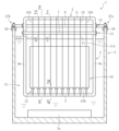
- Figures 1 to 14 show one embodiment of a sheet support tool, sheet material cleaning device, and cleaning method according to the present invention.
- the cleaning device 1 includes a sheet support 2 that supports the sheet material, and a cleaning tank 3 that can contain the sheet support 2 and cleaning liquid CL.
- a rectangular glass sheet GS is exemplified as the sheet material, but the shape and material of the sheet material are not limited to this embodiment.
- the thickness of the glass sheet GS is, for example, 0.01 mm or more and 0.2 mm or less.
- the length of one side of the glass sheet GS is, for example, 100 mm or more and 1000 mm or less.
- the sheet support 2 has a rectangular frame 4 that supports the glass sheet GS.
- the frame 4 includes a first bar 5, a second bar 6 that faces the first bar 5, a third bar 7 that faces the first bar 5, a fourth bar 8 for fixing the frame 4 to the cleaning tank 3, and side bars 9a and 9b that connect the first bar 5 and the second bar 6.
- the sheet support 2 further includes a plurality of support wires 10 stretched across the first bar 5 and the second bar 6, a plurality of restraining wires 11 stretched across the first bar 5 and the third bar 7, and a plurality of end supports 12 that support the lower end GSb of the glass sheet GS.
- the first bar 5, the second bar 6, the third bar 7, and the fourth bar 8 extend in parallel along the horizontal direction.
- Each of the bars 5 to 8 is configured as a synthetic resin tube having a circular cross-sectional shape, but the shape and material of each of the bars 5 to 8 are not limited to this embodiment.
- the direction along the longitudinal direction of each of the bars 5 to 8 may be referred to as the "width direction.”
- the side bars 9a, 9b include a first side bar 9a that connects one end of the first bar 5 to one end of the second bar 6, and a second side bar 9b that connects the other end of the first bar 5 to the other end of the second bar 6.
- the first side bar 9a and the second side bar 9b are configured to be parallel in the vertical direction.
- Each side bar 9a, 9b is configured from a synthetic resin tube having a circular cross-sectional shape, but the shape and material of the side bars 9a, 9b are not limited to this embodiment.
- the first bar 5 is located at the bottom of the frame 4, and the second bar 6 is located at the top of the frame 4.
- the third bar 7 is located between the first bar 5 and the second bar 6 in the vertical direction. In other words, the third bar 7 is located lower in the vertical direction than the second bar 6.
- the fourth bar 8 is located between the first bar 5 and the third bar 7 in the vertical direction.
- the distance from the axis of the first bar 5 to the axis of the third bar 7 in the vertical direction is shorter than the distance from the axis of the first bar 5 to the axis of the second bar 6 in the vertical direction. Therefore, the restricting wire 11 stretched between the first bar 5 and the third bar 7 is shorter than the supporting wire 10 stretched between the first bar 5 and the second bar 6.
- the length dimension of the supporting wire 10 and the restricting wire 11 is greater than the length dimension of the glass sheet GS in the vertical direction.
- the third bar 7 is located on the front side of the frame 4
- the fourth bar 8 is located on the rear side of the frame 4.
- the third bar 7 is attached to the side bars 9a and 9b via fasteners 13. It is preferable that the length dimension of the third bar 7 is greater than the distance between the first side bar 9a and the second side bar 9b so that the third bar 7 can be fixed to the side bars 9a and 9b by the fasteners 13.
- the fixing device 13 of the third bar 7 fixes the third bar 7 to the side bars 9a, 9b so that the position of the third bar 7 relative to the longitudinal direction of the side bars 9a, 9b can be changed.
- the fixing device 13 includes a pair of fixing devices that support one end and the other end of the third bar 7. As shown in FIG. 3, the fixing device 13 has an annular portion 15 that is attached to the side bars 9a, 9b, and a support portion 16 that protrudes from the annular portion 15.
- the annular portion 15 is configured in a circular ring shape so that the side bars 9a, 9b can be inserted through it.
- the annular portion 15 has a screw hole that penetrates it in the thickness direction.
- a fixing member 17 such as a bolt is attached to this screw hole.
- the fixing member 17 contacts the surfaces of the side bars 9a, 9b inside the annular portion 15 through this screw hole.
- the annular portion 15 can move (slide) along the longitudinal direction of the side bars 9a, 9b by releasing the fixing by the fixing member 17. This allows the position of the annular portion 15 in the longitudinal direction (up and down direction) of the side bars 9a, 9b to be adjusted according to the size of the glass sheet GS.
- the support portion 16 of the fixing device 13 protrudes from the annular portion 15 toward the front side of the frame 4.
- the support portion 16 is formed of a long plate member, but the shape of the support portion 16 is not limited to this embodiment.
- the support portion 16 has a hole through which the third bar 7 can be inserted.
- the third bar 7 is supported by each fixing device 13 by having one end and the other end thereof inserted into the holes of each support portion 16 associated with the pair of fixing devices 13.
- the length of the fourth bar 8 is greater than the widthwise distance between the first side bar 9a and the second side bar 9b. That is, as shown in FIG. 1, each end of the fourth bar 8 protrudes outward in the widthwise direction beyond each of the side bars 9a, 9b. It is preferable that the length of the fourth bar 8 is greater than or equal to the width of the cleaning tank 3 so that the end of the fourth bar 8 is bridged across the top of the cleaning tank 3.
- the fourth bar 8 is attached to the side bars 9a and 9b via fasteners 14.
- the fasteners 14 for the fourth bar 8 include a pair of fasteners that support one end and the other end of the fourth bar 8.
- the fasteners 14 have an annular portion 18 that is attached to the side bars 9a and 9b, and a support portion 19 that protrudes from the annular portion 18.
- the annular portion 18 has a screw hole that penetrates through it in the thickness direction.
- a fixing member 20 such as a bolt is attached to this screw hole.
- the fixing member 20 contacts the surfaces of the side bars 9a, 9b inside the annular portion 18 through this screw hole.
- the annular portion 18 can move (slide) along the longitudinal direction of the side bars 9a, 9b by releasing the fixing by the fixing member 20. This allows the position of the annular portion 18 in the longitudinal direction (up and down direction) of the side bars 9a, 9b to be adjusted according to the size of the glass sheet GS.
- the support portion 19 of the fixing device 14 protrudes from the annular portion 18 toward the rear side of the frame 4.
- the support portion 19 of the fixing device 14 is formed of a long plate member, but the shape of the support portion 19 is not limited to this embodiment.
- the support portion 19 has a hole through which the fourth bar 8 can be inserted.
- the fourth bar 8 is supported by each fixing device 14 by having one end and the other end thereof inserted into the holes of each support portion 19 of the pair of fixing devices 14.
- the support wire 10 is hung between the first bar 5 and the second bar 6 so as to be parallel to the side bars 9a and 9b in a front view.
- the support wire 10 may be arranged so as to be inclined with respect to the side bars 9a and 9b.
- the restricting wire 11 is hung between the first bar 5 and the third bar 7 so as to be parallel to the side bars 9a and 9b in a front view.
- the restricting wire 11 may be arranged so as to be inclined with respect to the side bars 9a and 9b.
- the support wire 10 is configured to support one of the main surfaces GSa of the glass sheet GS.
- the support wire 10 is preferably configured from a synthetic resin, but the material of the support wire 10 is not limited to this embodiment.
- the support wire 10 is supported by the second bar 6 by wrapping a single wire around the second bar 6.
- the support wire 10 includes a first portion 10a that contacts the glass sheet GS and a second portion 10b that is located behind the first portion 10a and does not contact the glass sheet GS.
- the restricting wire 11 comes into contact with the glass sheet GS when the glass sheet GS is deformed, and serves to restrict the movement of the glass sheet GS so that the glass sheet GS does not deform further.
- the restricting wire 11 is preferably made of synthetic resin, but the material of the restricting wire 11 is not limited to this embodiment.
- the number of restricting wires 11 is equal to the number of supporting wires 10, but this is not limited thereto and may be different from the number of supporting wires 10.
- the widthwise positions of the restricting wires 11 coincide with the widthwise positions of the supporting wires 10, but this is not limited thereto and the widthwise positions of the restricting wires 11 and the widthwise positions of the supporting wires 10 may be different.
- the restraining wire 11 is supported by the third bar 7 by wrapping a single wire around the third bar 7.
- the restraining wire 11 has a first portion 11a that can contact the glass sheet GS and a second portion 11b that does not contact the glass sheet GS.
- the first portion 10a of the support wire 10 and the first portion 11a of the restricting wire 11 are configured to face each other. With this configuration, a storage space S is formed between the first portion 10a of the support wire 10 and the first portion 11a of the restricting wire 11, into which the glass sheet GS can be inserted and removed.
- the storage space S for the glass sheet GS is configured such that the first portion 10a of the support wire 10 and the first portion 11a of the restraining wire 11 form a predetermined angle ⁇ 1.
- This angle ⁇ 1 is preferably 5° or more and 10° or less.
- the distance between the support wire 10 and the restraining wire 11 gradually decreases downward (from the second bar 6 to the first bar 5).
- the storage space S is configured to easily accommodate the glass sheet GS, and to minimize deformation of the lower end portion GSb of the glass sheet GS after the glass sheet GS is accommodated.
- the support wire 10A and the restricting wire 11A located at the outermost position in the width direction of the frame 4 are fixed to the second bar 6 and the third bar 7 in a manner different from that of the other wires 10, 11. That is, the support wire 10 and the restricting wire 11 located in the middle of the width direction have first portions 10a, 11a and second portions 10b, 11b in the example shown in Figures 4 and 5, but the support wire 10A and the restricting wire 11A located at the outermost position in the width direction only have first portions 10a, 11a, as shown in Figure 6.
- each wire 10A, 11A are wound around the second bar 6 and the third bar 7, and then these ends are tied to the middle of each wire 10A, 11A in the vicinity of the second bar 6 and the third bar 7.
- the angle ⁇ 2 between the first portion 10a of the support wire 10A and the first portion 11a of the restricting wire 11A is larger than the above-mentioned angle ⁇ 1 ( ⁇ 2> ⁇ 1).
- the glass sheet GS can be stored suitably in the storage space S.
- the end support 12 is provided at the bottom of the frame 4. Specifically, the end support 12 is provided above the first bar 5 in the vicinity of the first bar 5.
- the number of end supports 12 is equal to the number of support wires 10 or the number of restricting wires 11, but is not limited thereto and may be less than the number of each wire 10, 11.
- the end support 12 has a structure that allows the support wire 10 and the restraining wire 11 to be inserted therein.
- the end support 12 has a first support portion 21 that supports the lower end portion GSb of the glass sheet GS, and a second support portion 22 that supports the first support portion 21.
- the first support portion 21 is formed in a disk shape from an elastic body such as rubber, but the material and shape of the first support portion 21 are not limited to this embodiment.
- the first support portion 21 has a first insertion hole 23 through which the support wire 10 is inserted, a second insertion hole 24 through which the restraining wire 11 is inserted, and a support surface 25 that supports the lower end portion GSb of the glass sheet GS.
- the first insertion hole 23 and the second insertion hole 24 are formed in the first support portion 21 at a predetermined distance so that the support wire 10 and the restraining wire 11 do not come into contact with each other. This distance is preferably greater than the thickness of the glass sheet GS.
- the first support portion 21 fixes the support wire 10 and the restricting wire 11 while separating them.
- the support wire 10 and the restricting wire 11 are supported by the frame 4 and the end support 12 above the end support 12 without crossing each other.
- the support surface 25 is the central portion of the first support portion 21 and is formed between the first insertion hole 23 and the second insertion hole 24.
- the second support part 22 is cylindrical and made of synthetic resin or metal, but the material and shape of the second support part 22 are not limited to this embodiment.
- the second support part 22 is connected to the lower part of the first support part 21.
- the second support part 22 can pass the support wire 10 inserted into the first insertion hole 23 of the first support part 21 and the restricting wire 11 inserted into the second insertion hole 24 together.
- the lower part of the second support part 22 has an opening so that the support wire 10 and the restricting wire 11 can be brought out to the outside.
- the lower portion of the support wire 10 and the lower portion of the restricting wire 11 are fixed to the first bar 5.
- the support wire 10 can be interposed between the first bar 5 and the second bar 6 in a state where tension is applied.
- the restricting wire 11 can be interposed between the first bar 5 and the third bar 7 in a state where tension is applied.
- the portion of the support wire 10 wound around the first bar 5 can be moved along the longitudinal direction of the first bar 5.
- the portion of the support wire 10 wound around the second bar 6 can be moved along the longitudinal direction of the second bar 6.
- the support wire 10 can change its position in the width direction. This makes it possible to adjust the spacing between the multiple support wires 10 according to the size and thickness of the glass sheet GS.
- the portion of the restricting wire 11 that is wound around the first bar 5 and the portion that is wound around the third bar 7 can be moved in the width direction. This allows the widthwise position and spacing of the restricting wire 11 to be adjusted.
- Figure 8 shows another example of the end support 12.
- the first support portion 21 of the end support 12 has an annular body 26 made of an elastic material such as rubber.
- the annular body 26 has a hole 26a in the center through which the support wire 10 and the restraining wire 11 can be inserted.
- a portion of the upper surface of the annular body 26 serves as a support surface 25 that supports the lower end portion GSb of the glass sheet GS.
- the cleaning tank 3 can accommodate multiple sheet supports 2.
- the cleaning tank 3 includes an ultrasonic generator 3a that generates ultrasonic waves, and support devices 27a and 27b that support the frame 4 in an inclined position.
- the ultrasonic generator 3a is provided at the bottom of the cleaning tank 3, but the position and number of the ultrasonic generators 3a are not limited to this embodiment.
- the support devices 27a, 27b include a first support device 27a that supports one end of the fourth bar 8 and a second support device 27b that supports the other end of the fourth bar 8.
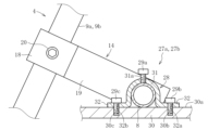
- each support device 27a, 27b includes a pressing member 28 that contacts the fourth bar 8 of the frame 4, fixing members 29a-29b that fix the pressing member 28 to the cleaning tank 3, and a support base 30 that supports the fourth bar 8 and the pressing member 28.
- the holding member 28 has a holding portion 31 that contacts the fourth bar 8, and a fixing portion 32 that is fixed to the cleaning tank 3.
- the holding portion 31 is configured in a curved shape (arc-shaped) to correspond to the shape of the fourth bar 8.
- the holding portion 31 has a through hole (hereinafter referred to as the "first through hole") 31a at its top into which the fixing member 29a fits.
- the first through hole 31a is configured as a screw hole.
- the fixing parts 32 are a pair of flat plate-shaped parts that are integrally provided at one end and the other end of the pressing part 31.
- Each fixing part 32 has a pair of through holes 32a, 32b (hereinafter referred to as the "second through hole” and the “third through hole”) into which the fixing members 29b, 29c are inserted.
- the fixing members 29a to 29b include a first fixing member 29a that fits into the first through hole 31a, a second fixing member 29b that fits into the second through hole 32a, and a third fixing member 29c that fits into the third through hole 32b.
- Each of the fixing members 29a to 29c is made of a screw member such as a bolt having a male thread.
- the end of the first fixing member 29a contacts the outer surface of the fourth bar 8 located inside the retaining portion 31 through the first through hole 31a.
- the second fixing member 29b and the third fixing member 29c fix the fixing portion 32 to the support base 30 through the second through hole 32a and the third through hole 32b. This allows the fourth bar 8 to be fixed to the support base 30 so that the frame 4 is in an inclined position.
- the support base 30 is provided on the upper part of the wall of the cleaning tank 3.
- the support base 30 has a support surface 30a that contacts the fourth bar 8 of the frame 4 and the support devices 27a, 27b.
- the support surface 30a has a number of screw holes 30b, 30c into which the second fixing member 29b and the third fixing member 29c are inserted.
- FIG. 10 shows another example of the support devices 27a, 27b.
- the support devices 27a, 27b do not have the first through hole 31a and first fixing member 29a in the example of FIG. 9.
- the support devices 27a, 27b can fix the fourth bar 8 to the support base 30 by pressing the fourth bar 8 with a pair of fixing members (second fixing member 29b and third fixing member 29c) inserted into the respective through holes 32a, 32b of the pair of fixing portions 32 of the pressing member 28 and the pressing portion 31.
- the following describes a method for cleaning glass sheets GS using the above-mentioned cleaning device 1.
- This method includes a preparation step and a cleaning step.
- the preparation step includes a storage step of storing the glass sheet GS in the sheet support 2, an immersion step of immersing the sheet support 2 storing the glass sheet GS in the cleaning liquid CL contained in the cleaning tank 3, and a fixing step of fixing the sheet support 2 to the cleaning tank 3.
- the glass sheet GS is accommodated in the accommodation space S formed in the frame 4.
- the glass sheet GS is lowered from above the frame 4, and its lower end GSb is brought into contact with the support wire 10 (first portion 10a) of the frame 4.
- the lower end GSb of the glass sheet GS is slid relative to the support wire 10 and moved downward. That is, in the accommodation step, the support wire 10 functions as a guide portion that guides the glass sheet GS into the accommodation space S.
- the accommodation step is completed by bringing the lower end GSb of the glass sheet GS into contact with the support surface 25 of the end support 12.
- the glass sheet GS is in a state in which one main surface GSa is supported by the support wire 10 and the lower end GSb is supported by the end support 12 (a state shown by the two-dot chain line in FIG. 11).
- the frame 4 containing the glass sheet GS is moved downward from an upper position in the cleaning tank 3.
- the frame 4 is immersed in the cleaning liquid CL in the cleaning tank 3 from its lower part (first bar 5).
- part of the glass sheet GS may float up and become deformed while the frame 4 is immersed in the cleaning liquid CL.
- the restraining wire 11 of the frame 4 comes into contact with part of the deformed glass sheet GS, preventing excessive deformation of the glass sheet GS. This reliably prevents damage to the glass sheet GS due to deformation.
- the frame 4 descends in the cleaning tank 3 until the fourth bar 8 comes into contact with the support table 30 of the support devices 27a and 27b.
- the fourth bar 8 of the frame 4 is brought into contact with the support surface 30a of the support base 30 of the cleaning tank 3.
- the pressing member 28 is placed on the fourth bar 8.
- the pressing portion 31 of the pressing member 28 comes into contact with the fourth bar 8
- the fixing portion 32 of the pressing member 28 comes into contact with the support surface 30a of the support base 30.
- the second through hole 32a and the third through hole 32b of the fixing portion 32 are aligned with the pair of screw holes 30b, 30c of the support base 30, and the second fixing member 29b and the third fixing member 29c are inserted into the respective through holes 32a, 32b and the respective screw holes 30b, 30c.
- the pressing member 28 is fixed to the support base 30.
- the frame 4 is placed in an inclined position, the first fixing member 29a is inserted into the first through-hole 31a of the pressing member 28, and the fourth bar 8 is fixed.
- the frame 4 is supported by the support devices 27a, 27b while maintaining the inclined position.
- the inclination angle ⁇ (see FIG. 2) of the frame 4 (side bars 9a, 9b) with respect to the vertical direction is 65° or more and 85° or less.
- the glass sheet GS contained in the frame 4 is supported by the frame 4 in an inclined position and is entirely immersed in the cleaning liquid CL in the cleaning tank 3.
- the ultrasonic generator 3a in the cleaning tank 3 is started, and the glass sheet GS supported by the sheet support 2 is cleaned with the cleaning liquid CL.
- the frame 4 is released from the support devices 27a and 27b, and the frame 4 is removed from the cleaning tank 3 together with the glass sheet GS.
- the contact area of the support wire 10 of the sheet support device 2 with the glass sheet GS is extremely small, and no large impact is applied to the glass sheet GS. Moreover, since the support wire 10 contacts only one of the main surfaces GSa of the glass sheet GS without contacting the side ends of the glass sheet GS, no large impact is applied to the side ends of the glass sheet GS. In this way, by supporting the glass sheet GS with the support wire 10, damage to the main surface and ends of the glass sheet GS during the preparation process and cleaning process can be effectively prevented.
- the sheet support 2 can adequately support the lower end GSb of the glass sheet GS without damaging it by configuring the first support portion 21 of the end support 12 from an elastic material.
- the present invention is not limited to the configuration of the above embodiment, nor is it limited to the above-mentioned effects. Various modifications of the present invention are possible without departing from the gist of the present invention.
- the support wire 10 and the restricting wire 11 are fixed by wrapping them around the first bar 5, but the present invention is not limited to this configuration.
- the support wire 10 and the restricting wire 11 may be fixed to the first bar 5 by gluing or welding, or by using pins or screw members.
- each wire 10, 11 may be fixed to the first bar 5 by forming through holes in the first bar 5 and inserting the support wire 10 and the restricting wire 11 through the through holes.
- the support wire 10 may be fixed to the second bar 6, and the restricting wire 11 may be fixed to the third bar 7.
Landscapes
- Packaging Frangible Articles (AREA)
- Cleaning Implements For Floors, Carpets, Furniture, Walls, And The Like (AREA)
- Cleaning By Liquid Or Steam (AREA)
Abstract
La présente invention concerne un outil de support de feuille (2) comprenant : un cadre (4) ; et un fil de support (10) qui est disposé sur le cadre (4) et qui est destiné à supporter un matériau en feuille (GS). Le cadre (4) est pourvu : d'une première barre (5) et d'une seconde barre (6) se faisant face ; et de barres latérales (9a, 9b) qui relient la première barre (5) et la seconde barre (6). Le fil de support (10) comprend une pluralité de fils de support qui s'étendent entre la première barre (5) et la seconde barre (6). Le fil de support (10) est conçu pour supporter une surface principale (GSa) du matériau en feuille (GS).
Applications Claiming Priority (2)
| Application Number | Priority Date | Filing Date | Title |
|---|---|---|---|
| JP2023-190114 | 2023-11-07 | ||
| JP2023190114A JP2025077713A (ja) | 2023-11-07 | 2023-11-07 | シート支持具、シート材の洗浄装置及び洗浄方法 |
Publications (1)
| Publication Number | Publication Date |
|---|---|
| WO2025100247A1 true WO2025100247A1 (fr) | 2025-05-15 |
Family
ID=95695393
Family Applications (1)
| Application Number | Title | Priority Date | Filing Date |
|---|---|---|---|
| PCT/JP2024/037912 Pending WO2025100247A1 (fr) | 2023-11-07 | 2024-10-24 | Outil de support de feuille, appareil de nettoyage de matériau en feuille et procédé de nettoyage |
Country Status (3)
| Country | Link |
|---|---|
| JP (1) | JP2025077713A (fr) |
| TW (1) | TW202521236A (fr) |
| WO (1) | WO2025100247A1 (fr) |
Citations (8)
| Publication number | Priority date | Publication date | Assignee | Title |
|---|---|---|---|---|
| JPS5075270U (fr) * | 1973-11-09 | 1975-07-01 | ||
| JPH0647360A (ja) * | 1992-07-29 | 1994-02-22 | Syst Sutatsuku:Kk | 超音波洗浄装置 |
| JPH11319735A (ja) * | 1998-05-07 | 1999-11-24 | Hitoshi Kokubu | 洗浄装置 |
| JP2001286838A (ja) * | 2000-04-07 | 2001-10-16 | Dalton Corp | 超音波洗浄装置並びにこれを用いた洗浄方法 |
| US20060117654A1 (en) * | 2004-10-12 | 2006-06-08 | Canhoto Alfredo J | Bench scale apparatus to model and develop biopharmaceutical cleaning procedures |
| JP2007216431A (ja) * | 2006-02-14 | 2007-08-30 | Somakkusu Kk | 金型洗浄装置 |
| CN106216302A (zh) * | 2016-09-14 | 2016-12-14 | 国家电网公司 | 全玻璃注射器超清洁刷洗机器的控制系统 |
| JP2018075536A (ja) * | 2016-11-10 | 2018-05-17 | 上村工業株式会社 | 超音波処理装置 |
-
2023
- 2023-11-07 JP JP2023190114A patent/JP2025077713A/ja active Pending
-
2024
- 2024-10-24 WO PCT/JP2024/037912 patent/WO2025100247A1/fr active Pending
- 2024-10-30 TW TW113141386A patent/TW202521236A/zh unknown
Patent Citations (8)
| Publication number | Priority date | Publication date | Assignee | Title |
|---|---|---|---|---|
| JPS5075270U (fr) * | 1973-11-09 | 1975-07-01 | ||
| JPH0647360A (ja) * | 1992-07-29 | 1994-02-22 | Syst Sutatsuku:Kk | 超音波洗浄装置 |
| JPH11319735A (ja) * | 1998-05-07 | 1999-11-24 | Hitoshi Kokubu | 洗浄装置 |
| JP2001286838A (ja) * | 2000-04-07 | 2001-10-16 | Dalton Corp | 超音波洗浄装置並びにこれを用いた洗浄方法 |
| US20060117654A1 (en) * | 2004-10-12 | 2006-06-08 | Canhoto Alfredo J | Bench scale apparatus to model and develop biopharmaceutical cleaning procedures |
| JP2007216431A (ja) * | 2006-02-14 | 2007-08-30 | Somakkusu Kk | 金型洗浄装置 |
| CN106216302A (zh) * | 2016-09-14 | 2016-12-14 | 国家电网公司 | 全玻璃注射器超清洁刷洗机器的控制系统 |
| JP2018075536A (ja) * | 2016-11-10 | 2018-05-17 | 上村工業株式会社 | 超音波処理装置 |
Also Published As
| Publication number | Publication date |
|---|---|
| TW202521236A (zh) | 2025-06-01 |
| JP2025077713A (ja) | 2025-05-19 |
Similar Documents
| Publication | Publication Date | Title |
|---|---|---|
| US5503173A (en) | Wafer cleaning tank | |
| JP4934079B2 (ja) | 超音波洗浄装置及び超音波洗浄方法 | |
| CN103369840A (zh) | 基板处理装置 | |
| WO2025100247A1 (fr) | Outil de support de feuille, appareil de nettoyage de matériau en feuille et procédé de nettoyage | |
| JPWO2014112444A1 (ja) | ガラス板収納体及び化学強化ガラスの製造方法 | |
| JP5637974B2 (ja) | 基板洗浄装置及び基板洗浄方法 | |
| KR20120086873A (ko) | 웨이퍼 분리 장치 | |
| CN217017851U (zh) | 一种用于光学窗口片的清洗治具和超声波清洗设备 | |
| JP4634333B2 (ja) | 基板処理装置及び基板処理方法 | |
| JP2005046687A (ja) | ガラス基板洗浄装置 | |
| KR101891783B1 (ko) | 웨이퍼 분리 장치 | |
| US12465958B2 (en) | Ultrasonic cleaning unit with improved cleaning performance, and substrate cleaning apparatus including the same | |
| JP3758491B2 (ja) | 実装基板の下受け装置における下受けピン取り付け方法 | |
| CN113597141B (zh) | 挂篮和线路板的孔金属化方法 | |
| JP5118560B2 (ja) | ウエハ収納キャリア | |
| JP3905239B2 (ja) | 基板保持具および基板処理装置 | |
| JP2009212324A (ja) | 基板保持用治具 | |
| JP2000129471A (ja) | 基板処理装置 | |
| CN108971176B (zh) | 清洗用保持器 | |
| JP2003088825A (ja) | ワーク洗浄用治具 | |
| JPS5968930A (ja) | ウエハ洗浄装置用ウエハ保持具 | |
| JPH04288899A (ja) | プリント基板の搬送装置 | |
| JP2001308171A (ja) | バックグラインドウェーハの輸送容器及びバックグラインドウェーハの収納方法 | |
| JP2008132417A (ja) | ブロー洗浄装置 | |
| CN118543596A (zh) | 一种清洗工件的方法和装置 |
Legal Events
| Date | Code | Title | Description |
|---|---|---|---|
| 121 | Ep: the epo has been informed by wipo that ep was designated in this application |
Ref document number: 24888544 Country of ref document: EP Kind code of ref document: A1 |