WO2025100304A1 - Élément de fixation - Google Patents
Élément de fixation Download PDFInfo
- Publication number
- WO2025100304A1 WO2025100304A1 PCT/JP2024/038562 JP2024038562W WO2025100304A1 WO 2025100304 A1 WO2025100304 A1 WO 2025100304A1 JP 2024038562 W JP2024038562 W JP 2024038562W WO 2025100304 A1 WO2025100304 A1 WO 2025100304A1
- Authority
- WO
- WIPO (PCT)
- Prior art keywords
- mounting hole
- rotation guide
- fastener
- guide portion
- longitudinal
- Prior art date
- Legal status (The legal status is an assumption and is not a legal conclusion. Google has not performed a legal analysis and makes no representation as to the accuracy of the status listed.)
- Pending
Links
Images






Classifications
-
- F—MECHANICAL ENGINEERING; LIGHTING; HEATING; WEAPONS; BLASTING
- F16—ENGINEERING ELEMENTS AND UNITS; GENERAL MEASURES FOR PRODUCING AND MAINTAINING EFFECTIVE FUNCTIONING OF MACHINES OR INSTALLATIONS; THERMAL INSULATION IN GENERAL
- F16B—DEVICES FOR FASTENING OR SECURING CONSTRUCTIONAL ELEMENTS OR MACHINE PARTS TOGETHER, e.g. NAILS, BOLTS, CIRCLIPS, CLAMPS, CLIPS OR WEDGES; JOINTS OR JOINTING
- F16B19/00—Bolts without screw-thread; Pins, including deformable elements; Rivets
- F16B19/04—Rivets; Spigots or the like fastened by riveting
- F16B19/08—Hollow rivets; Multi-part rivets
- F16B19/10—Hollow rivets; Multi-part rivets fastened by expanding mechanically
-
- F—MECHANICAL ENGINEERING; LIGHTING; HEATING; WEAPONS; BLASTING
- F16—ENGINEERING ELEMENTS AND UNITS; GENERAL MEASURES FOR PRODUCING AND MAINTAINING EFFECTIVE FUNCTIONING OF MACHINES OR INSTALLATIONS; THERMAL INSULATION IN GENERAL
- F16B—DEVICES FOR FASTENING OR SECURING CONSTRUCTIONAL ELEMENTS OR MACHINE PARTS TOGETHER, e.g. NAILS, BOLTS, CIRCLIPS, CLAMPS, CLIPS OR WEDGES; JOINTS OR JOINTING
- F16B21/00—Means for preventing relative axial movement of a pin, spigot, shaft or the like and a member surrounding it; Stud-and-socket releasable fastenings
- F16B21/02—Releasable fastening devices locking by rotation
- F16B21/04—Releasable fastening devices locking by rotation with bayonet catch
Definitions
- the present invention relates to a fastener that is attached to a mounting hole.
- Patent Document 1 discloses a clip that is attached to an attachment hole.
- This clip has a pair of clamping pieces whose tip ends are connected, and a flange portion formed on the base end side of the clamping pieces.
- the clamping pieces are formed with a flexible elastic piece through a slit, and the elastic piece is provided with a locking shoulder that engages with the rear periphery of the attachment hole.
- the object of the present invention is to provide a fastener that prevents the entire fastener from coming off the mounting hole even if the fastener body comes off the mounting hole, and further improves attachment.
- one aspect of the present invention is a fastener that is attached to a mounting member, and includes a main body having an engagement portion that engages with the mounting member, a longitudinal portion extending from the main body, and a rotation guide portion connected to the longitudinal portion.
- the rotation guide portion has an abutment surface that abuts against the edge of the mounting hole when the mounting member is inserted into the mounting hole, and a retaining portion that prevents the rotation guide portion from coming out of the mounting hole after insertion into the mounting hole.
- the abutment surface When inserted into the mounting hole, the abutment surface abuts against the edge of the mounting hole, causing the rotation guide portion to rotate around an axis along the longitudinal direction of the longitudinal portion, and the longitudinal portion is flexible so as to twist due to the rotation of the rotation guide portion.
- the present invention provides a fastener that prevents the entire fastener from coming off the mounting hole even if the fastener body comes off the mounting hole, thereby improving attachment properties.
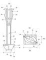
- FIG. 2 is a perspective view of the fastener of the first embodiment.
- FIG. 2(a) is a front view of the fastener of the first embodiment
- FIG. 2(b) is a bottom view of the fastener of the first embodiment.
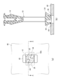
- 13 is a diagram for explaining a process of attaching the fastener to the mounting member, and shows the state before the rotation guide portion is inserted into the mounting hole formed in the mounting member.
- FIG. 4(a) is a diagram showing the fastener and the mounting member shown in FIG. 3 as viewed from below
- FIG. 4(b) is a cross-sectional view of the fastener shown in FIG. 4(a) taken along line AA.
- FIG. 13 is a diagram for explaining the process of attaching the fastener to the mounting member, showing the state in which the rotation guide portion is inserted into the mounting hole.
- FIG. 13 is a diagram for explaining the process of attaching the fastener to the mounting member, and shows the state after the fastener has been completely attached to the mounting hole.
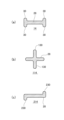
- FIG. FIG. 2 is a cross-sectional view of an elongate portion of the fastener.
- FIG. 13 is a perspective view of an assembly with a fastener of a second embodiment attached.
- FIG. 9 is an exploded view of the assembly shown in FIG. 8 and a perspective view of the fastener and mounting member of the second embodiment.
- FIG. 1 is a perspective view of the fastener 10 of the first embodiment.
- FIG. 2(a) is a front view of the fastener 10 of the first embodiment
- FIG. 2(b) is a bottom view of the fastener 10 of the first embodiment.
- the fastener 10 is used to attach a part to an attachment member.
- the attachment member is a panel that constitutes a vehicle door or a vehicle armrest, and the part is an operating panel having buttons for opening and closing windows, etc.
- the fastener 10 comprises a main body portion 12, a longitudinal portion 14, and a rotation guide portion 16.
- the main body portion 12 engages with the edge of a mounting hole formed in the mounting member.
- the main body portion 12 has a locking leg portion 20, an inward extension portion 22, an inward protrusion portion 24, and a flange portion 26.
- the locking legs 20 are formed in a pair opposite each other and are flexibly arranged to move closer to or apart.
- the lower ends of the pair of locking legs 20 are connected, and the upper ends are free ends.
- the locking legs 20 lock onto the rear edge of the mounting hole to prevent the main body 12 from slipping out of the mounting hole.
- the flanges 26 protrude outward in the opposing direction from the upper ends of the locking legs 20 and lock onto the upper edge of the mounting hole.
- the inward extensions 22 extend from the inner surface of the locking leg 20 toward the lower end.
- the inward protrusions 24 protrude inward from the upper end of the locking leg 20.
- the pair of inward extensions 22 and the pair of inward protrusions 24 sandwich a boss formed on the part.
- the longitudinal portion 14 extends in the longitudinal direction from the main body portion 12.
- the longitudinal portion 14 has a band portion 28 and a protrusion portion 30.
- the band portion 28 extends in the longitudinal direction.
- the protrusion portion 30 protrudes from the band portion 28 and extends along the longitudinal direction.
- the longitudinal portion 14 can bend so as to twist around an axis along the longitudinal direction by rotation of the rotation guide portion 16, and can return to its original state after twisting.
- the rotation guide portion 16 can move back and forth between a normal reference position and a position rotated 90 degrees by the longitudinal portion 14.
- the rotation guide portion 16 is connected to the longitudinal portion 14.
- the rotation guide portion 16 has the function of guiding rotation when inserted into the mounting hole, and the function of preventing it from coming out of the mounting hole.
- the rotation guide portion 16 has a retaining portion 32, an abutment surface 34, a notch 36, a short diameter portion 38a, and a long diameter portion 38b.
- the anti-slip portion 32 is formed so as to protrude from the lower end of the elongated portion 14 in a direction perpendicular to the longitudinal direction of the elongated portion 14.
- the anti-slip portion 32 is formed in a flat shape. The anti-slip portion 32 prevents the rotation guide portion 16 from coming out of the mounting hole after being inserted into the mounting hole.
- the abutment surface 34 is located on the outer circumferential surface of the rotation guide portion 16, and is formed in a tapered shape that tapers from the edge of the retaining portion 32 toward the tip.
- the abutment surface 34 is formed to be curved in the circumferential direction from approximately the center of the long diameter portion 38b to the short diameter portion 38a.
- the abutment surfaces 34 are formed in pairs, are located diagonally with respect to the central axis of the rotation guide portion 16, and are inclined so as to intersect with the radial direction.
- the central axis of the rotation guide portion 16 is parallel to the longitudinal direction of the longitudinal portion 14.
- the abutment surface 34 abuts against the edge of the mounting hole when inserted into the mounting hole, and guides the rotation of the rotation guide portion 16.
- the rotation guide portion 16 when viewed in the longitudinal direction of the longitudinal portion 14, the rotation guide portion 16 is formed in a generally parallelogram shape and has a short diameter portion 38a and a long diameter portion 38b. At the outer periphery of the retaining portion 32, the portion constituting the short diameter portion 38a and the portion constituting the long diameter portion 38b partially overlap.
- the cutouts 36 are formed as a pair to cut out the lower part of the rotation guide portion 16.
- the pair of cutouts 36 are located diagonally with respect to the central axis of the rotation guide portion 16.
- the pair of abutment surfaces 34 and the pair of cutouts 36 are alternately arranged around the central axis of the rotation guide portion 16.
- the width W1 of the long diameter portion 38b is greater than the width W2 of the tip of the rotation guide portion 16. Therefore, the rotation guide portion 16 tapers toward the tip.
- a pair of corners 39 are formed on the outer periphery of the retaining portion 32.
- the corners 39 are formed at an acute angle ⁇ .
- the abutment surface 34 is inclined at the acute angle ⁇ from the corners 39, so that it can receive a rotational torque around the central axis when the abutment surface 34 on the short diameter portion 38a side abuts against the edge of the mounting hole.
- FIG. 3 is a diagram for explaining the process of attaching the fastener 10 to the mounting member 40, and shows the state before the rotation guide portion 16 is inserted into the mounting hole 42 formed in the mounting member 40.
- FIG. 4(a) is a view of the fastener 10 and mounting member 40 shown in FIG. 3 seen from below
- FIG. 4(b) is a cross-sectional view of the fastener 10 shown in FIG. 4(a) along line A-A.
- the mounting hole 42 formed in the mounting member 40 is formed in a substantially rectangular shape, and has a short side portion 42a and a long side portion 42b.
- the mounting hole 42 is not limited to a substantially rectangular shape, and may be formed in a substantially elliptical or elongated hole shape. In any case, the mounting hole 42 has a shape having a long portion and a short portion.
- the fastener 10 is inserted into the mounting hole 42 from the rotation guide 16 along the central axis. Because the locking legs 20 of the main body 12 have a width greater than the short side 42a, the orientation of the fastener 10 when inserted is predetermined, and the pair of locking legs 20 are inserted in a rotated position such that their opposing directions are aligned with the short side 42a.
- the abutment surface 34 abuts against the edge of the mounting hole 42.
- the orientation during insertion is fixed, and the long diameter portion 38b extends along the opposing direction of the pair of locking legs 20, so that the abutment point 44 of the abutment surface 34 abuts against the long side portion 42b of the mounting hole 42, as shown in FIG. 4(a) and FIG. 4(b).
- the abutment surface 34 When the abutment surface 34 comes into contact with the edge of the mounting hole 42, it receives a force in a direction that rotates the rotation guide portion 16 around the axis. This causes the rotation guide portion 16 to start rotating around the axis. Because the abutment surface 34 is curved in the circumferential direction, the abutment surface 34 can slide smoothly over the edge of the mounting hole 42. This allows the rotation of the rotation guide portion 16 to be smooth.
- FIG. 5 is a diagram for explaining the process of attaching the fastener 10 to the mounting member 40, and shows the state in which the rotation guide portion 16 is inserted into the mounting hole 42.
- the rotation guide portion 16 is in a position rotated 90 degrees from the normal reference position shown in FIG. 3.
- the longitudinal portion 14 is in a twisted state in response to the rotation of the rotation guide portion 16. This allows the rotation guide portion 16 to assume a rotational position that allows it to pass through the mounting hole 42 while maintaining the rotational position of the main body portion 12.
- the rotational position in which the rotation guide portion 16 can pass through the mounting hole 42 is the position in which the short diameter portion 38a fits within the short side portion 42a and the long diameter portion 38b fits within the long side portion 42b.
- the longitudinal portion 14 is long enough and thin enough to be twisted.
- the longitudinal portion 14 is longer than the main body portion 12 in the longitudinal direction, and a sufficient length is ensured.
- the width of the longitudinal portion 14 is smaller than the short side portion 42a of the mounting hole 42, and it can be inserted into the mounting hole 42 in a twisted state.
- Figure 6 is a diagram for explaining the process of attaching the fastener 10 to the mounting member 40, and shows the state in which the fastener 10 has been completely attached to the mounting hole 42.
- the pair of flanges 26 are hooked onto the long side 42b of the mounting hole 42.
- the operation panel (not shown) is clamped by the inward extension 22.
- the worker pulls the main body 12 out of the mounting hole 42 and removes the operation panel from the inward extension 22.
- the fastener 10 can be removed from the mounting hole 42 together with the operation panel, which returns it to the state before assembly, ensuring reassembly in the same way as conventional parts.
- the longitudinal portion 14 After passing through the mounting hole 42, the longitudinal portion 14 returns to its twisted state, rotating the rotation guide portion 16 to return the retaining portion 32 to a position where it can be prevented from falling out of the mounting hole 42. In this way, because the longitudinal portion 14 returns to its twisted state, the rotation guide portion 16 returns to its original position and the retaining portion 32 can assume a position where it can be caught in the mounting hole 42. Even if the main body portion 12 comes off the mounting hole 42 and tries to come out upward, the retaining portion 32 will eventually be caught in the mounting hole 42 to prevent it from falling out.
- Figure 7 is a cross-sectional view of the longitudinal portion of the fastener 10.
- the longitudinal portion 14 has a band portion 28 and a protrusion portion 30.
- the protrusion portion 30 protrudes from both edges of the band portion 28 in a direction perpendicular to the surface. This forms a cross section of the longitudinal portion 14 in a substantially H-shape.
- the protrusion portion 30 extends along the longitudinal direction of the longitudinal portion 14 as shown in Figure 1.
- Figure 7(b) is a cross-sectional view of a modified longitudinal portion 114.
- the longitudinal portion 114 has a band portion 28 and a protrusion portion 130.
- the protrusion portion 130 protrudes from the center of both sides of the band portion 28. This causes the cross section of the longitudinal portion 114 to be formed in a cross shape.
- Fig. 7(c) is a cross-sectional view of a longitudinal portion 214 of another modified example.
- the longitudinal portion 214 has a band portion 28 and a protrusion portion 230.
- the protrusion portion 30 shown in Fig. 7(a) protrudes from both sides and both edges of the band portion 28, whereas the protrusion portion 230 shown in Fig. 7(c) differs in that it protrudes from one edge of the band portion 28.
- the protrusion portion 230 is disposed diagonally with respect to the central axis of the band portion 28.
- FIG. 8 is a perspective view of an assembly to which the fastener 300 of the second embodiment is attached.
- FIG. 9 is an exploded view of the assembly shown in FIG. 8, and is a perspective view of the fastener 300 of the second embodiment and the mounting member 50.
- the fastener 300 also functions as a cover member, covering the bolt for fixing the mounting member 50 to the vehicle body.
- the mounting member 50 and the fastener 300 form, for example, a pull handle portion of the door trim.
- the mounting member 50 has a case portion 52, a first mounting hole 54, a second mounting hole 56, and an insertion hole 58.
- the case portion 52 shown in Figures 8 and 9 is on the back side, and the front side of the case portion 52 has a storage portion and an insertion hole 58.
- the first mounting holes 54 are provided as a pair penetrating through the bottom of the case portion 52.
- the second mounting hole 56 and the insertion hole 58 are provided as a pair penetrating through the bottom of the case portion 52.
- the storage portion is located between the first mounting hole 54 and the second mounting hole 56. A bolt is inserted through the insertion hole 58 to secure it to the vehicle body.
- the fastener 300 has a locking portion 312, a longitudinal portion 14, a rotation guide portion 16, a main body portion 318, and a retaining portion 32.
- the fastener 300 shown in FIG. 9 is the back side.
- the main body portion 318 is formed in a plate shape.
- the locking portions 312 are formed as a pair, protruding from the back surface of the main body portion 318.
- the locking portions 312 are formed in a claw shape.
- the longitudinal portion 14 extends in the longitudinal direction from the back surface of the main body portion 318, and is flexible so as to twist around an axis along the longitudinal direction.
- the rotation guide portion 16 is connected to the tip of the elongated portion 14.
- the configuration of the rotation guide portion 16 of the fastener 300 is the same as the rotation guide portion 16 shown in Figure 1.
- the pair of locking portions 312 are inserted into the pair of first mounting holes 54, respectively.
- the elongated portion 14 and the rotation guide portion 16 are inserted into the second mounting hole 56.
- the retaining portion 32 of the rotation guide portion 16 is hooked around the second mounting hole 56, preventing the fastener 300 from coming off the mounting member 50.
- the pair of first mounting holes 54 and second mounting holes 56 are rectangular holes.
- the process of attaching the fastener 300 to the mounting member 50 will be described.
- the fastener 300 is assembled to the mounting member 50.
- the rotation guide portion 16 is inserted into the second mounting hole 56.
- the abutment surface 34 abuts against the edge of the second mounting hole 56 and receives a rotational torque
- the longitudinal portion 14 twists around an axis along the longitudinal direction
- the rotation guide portion 16 rotates and passes through the second mounting hole 56.
- the rotation guide portion 16 After passing through the second mounting hole 56, the rotation guide portion 16 returns to its original rotation position due to the elastic recovery of the longitudinal portion 14, and the slip-out prevention portion 32 becomes a slip-out prevention portion.
- the locking portion 312 is pushed into the first mounting hole 54 and locks onto the edge of the first mounting hole 54.
- the rotation guide portion 16 rotates and is attached, so that the fastener can be easily attached without changing the position of the main body portion 318.
- the worker releases the lock by pushing the locking portion 312 with a tool in a direction away from the first mounting hole 54, and with the retaining portion 32 hooked into the second mounting hole 56, the worker can remove the retaining portion 32 from the second mounting hole 56 by grasping the longitudinal portion 14 with a tool and twisting it by about 90 degrees.
- the mounting hole 42 is generally rectangular, but this is not limiting.
- the mounting hole 42 may be generally cross-shaped.
- the rotation guide portion has a retaining portion formed in a generally cross shape and a tapered curved contact surface. In this embodiment, the rotation guide portion rotates in a range of 30 degrees to 45 degrees.
- the present invention relates to a fastener that is attached to a mounting hole.
Landscapes
- Engineering & Computer Science (AREA)
- General Engineering & Computer Science (AREA)
- Mechanical Engineering (AREA)
- Insertion Pins And Rivets (AREA)
- Snaps, Bayonet Connections, Set Pins, And Snap Rings (AREA)
Abstract
La présente invention concerne un élément de fixation 10 destiné à être monté dans un trou de montage d'un élément de montage, ledit élément de fixation comprenant : une partie principale 12 ayant une partie de mise en prise pour venir en prise avec l'élément de montage ; une partie longitudinale 14 s'étendant à partir de la partie principale 12 ; et une partie d'induction de rotation 16 accouplée à la partie longitudinale 14. La partie d'induction de rotation 16 présente une surface de contact 34 qui entre en contact avec le bord du trou de montage lorsqu'elle est insérée dans le trou de montage et une partie de retenue 32 qui empêche la partie d'induction de rotation 16 de tomber du trou de montage après avoir été insérée dans le trou de montage. La partie d'induction de rotation 16 tourne autour d'un axe le long de la direction longitudinale lorsque la surface de contact 34 entre en contact avec le bord du trou de montage au moment de l'insertion dans le trou de montage, et la partie longitudinale 14 est flexible de façon à être tordue en raison de la rotation de la partie d'induction de rotation 16.
Applications Claiming Priority (2)
| Application Number | Priority Date | Filing Date | Title |
|---|---|---|---|
| JP2023-192073 | 2023-11-10 | ||
| JP2023192073 | 2023-11-10 |
Publications (1)
| Publication Number | Publication Date |
|---|---|
| WO2025100304A1 true WO2025100304A1 (fr) | 2025-05-15 |
Family
ID=95695969
Family Applications (1)
| Application Number | Title | Priority Date | Filing Date |
|---|---|---|---|
| PCT/JP2024/038562 Pending WO2025100304A1 (fr) | 2023-11-10 | 2024-10-29 | Élément de fixation |
Country Status (1)
| Country | Link |
|---|---|
| WO (1) | WO2025100304A1 (fr) |
Citations (3)
| Publication number | Priority date | Publication date | Assignee | Title |
|---|---|---|---|---|
| JP2006176089A (ja) * | 2004-12-24 | 2006-07-06 | Toyoda Gosei Co Ltd | ピラーガーニッシュ |
| JP2007098986A (ja) * | 2005-09-30 | 2007-04-19 | Inoac Corp | 車両内装部材 |
| EP3453576A1 (fr) * | 2017-09-07 | 2019-03-13 | RENAULT s.a.s. | Dispositif de fixation d'un montant de baie équipé d'un airbag |
-
2024
- 2024-10-29 WO PCT/JP2024/038562 patent/WO2025100304A1/fr active Pending
Patent Citations (3)
| Publication number | Priority date | Publication date | Assignee | Title |
|---|---|---|---|---|
| JP2006176089A (ja) * | 2004-12-24 | 2006-07-06 | Toyoda Gosei Co Ltd | ピラーガーニッシュ |
| JP2007098986A (ja) * | 2005-09-30 | 2007-04-19 | Inoac Corp | 車両内装部材 |
| EP3453576A1 (fr) * | 2017-09-07 | 2019-03-13 | RENAULT s.a.s. | Dispositif de fixation d'un montant de baie équipé d'un airbag |
Similar Documents
| Publication | Publication Date | Title |
|---|---|---|
| US6155739A (en) | Temporary connection device for universal joint | |
| US20110116890A1 (en) | Fastener | |
| WO2015079959A1 (fr) | Pince, et structure de fixation de garniture de montant | |
| CN108223510B (zh) | 用于将第一元件固定在第二元件上的夹具 | |
| EP1936018B1 (fr) | Système pour fixation sans vis d'un corps à un panneau | |
| JP4025710B2 (ja) | ケーブルの取付構造 | |
| JPS5838644B2 (ja) | フアスナノコウゾウ | |
| JP2000274412A (ja) | 壁面等に器具を取り付けるためのアンカー | |
| JP4073087B2 (ja) | 部品取付け用クリップ | |
| JP2004040879A (ja) | 電気接続箱の取付構造 | |
| KR0146395B1 (ko) | 클립 | |
| US20090001735A1 (en) | Mechanism for Securing the Handle of a Door or Window | |
| JPH0524803Y2 (fr) | ||
| JP4036557B2 (ja) | クランプのロック機構 | |
| US2876515A (en) | Snap clip | |
| JP3843610B2 (ja) | ヨークのクリップ | |
| JPH09112512A (ja) | クリップの取付構造 | |
| JP4597943B2 (ja) | スタッド固定クリップ | |
| JP2020161349A (ja) | 端子固定構造 | |
| EP4100654B1 (fr) | Élément de fixation à bascule et procédé d'utilisation | |
| KR0136221B1 (ko) | 플로어카펫 고정구 | |
| JP2024119676A (ja) | ワイヤハーネス用クランプの取付構造 | |
| JPH11280725A (ja) | 抜け止めクリップ | |
| JP2886074B2 (ja) | キャップにより孔を開放可能に閉止する構造 | |
| JPH08178133A (ja) | ベルトクリップ |
Legal Events
| Date | Code | Title | Description |
|---|---|---|---|
| 121 | Ep: the epo has been informed by wipo that ep was designated in this application |
Ref document number: 24888601 Country of ref document: EP Kind code of ref document: A1 |