WO2025141982A1 - Élément de suspension et procédé de fabrication d'élément de suspension - Google Patents
Élément de suspension et procédé de fabrication d'élément de suspension Download PDFInfo
- Publication number
- WO2025141982A1 WO2025141982A1 PCT/JP2024/033685 JP2024033685W WO2025141982A1 WO 2025141982 A1 WO2025141982 A1 WO 2025141982A1 JP 2024033685 W JP2024033685 W JP 2024033685W WO 2025141982 A1 WO2025141982 A1 WO 2025141982A1
- Authority
- WO
- WIPO (PCT)
- Prior art keywords
- mass
- less
- range
- aluminum alloy
- suspension member
- Prior art date
- Legal status (The legal status is an assumption and is not a legal conclusion. Google has not performed a legal analysis and makes no representation as to the accuracy of the status listed.)
- Pending
Links
Images




Classifications
-
- B—PERFORMING OPERATIONS; TRANSPORTING
- B21—MECHANICAL METAL-WORKING WITHOUT ESSENTIALLY REMOVING MATERIAL; PUNCHING METAL
- B21J—FORGING; HAMMERING; PRESSING METAL; RIVETING; FORGE FURNACES
- B21J5/00—Methods for forging, hammering, or pressing; Special equipment or accessories therefor
-
- B—PERFORMING OPERATIONS; TRANSPORTING
- B22—CASTING; POWDER METALLURGY
- B22C—FOUNDRY MOULDING
- B22C9/00—Moulds or cores; Moulding processes
- B22C9/22—Moulds for peculiarly-shaped castings
-
- B—PERFORMING OPERATIONS; TRANSPORTING
- B22—CASTING; POWDER METALLURGY
- B22D—CASTING OF METALS; CASTING OF OTHER SUBSTANCES BY THE SAME PROCESSES OR DEVICES
- B22D21/00—Casting non-ferrous metals or metallic compounds so far as their metallurgical properties are of importance for the casting procedure; Selection of compositions therefor
- B22D21/02—Casting exceedingly oxidisable non-ferrous metals, e.g. in inert atmosphere
- B22D21/04—Casting aluminium or magnesium
-
- B—PERFORMING OPERATIONS; TRANSPORTING
- B60—VEHICLES IN GENERAL
- B60G—VEHICLE SUSPENSION ARRANGEMENTS
- B60G7/00—Pivoted suspension arms; Accessories thereof
-
- C—CHEMISTRY; METALLURGY
- C22—METALLURGY; FERROUS OR NON-FERROUS ALLOYS; TREATMENT OF ALLOYS OR NON-FERROUS METALS
- C22C—ALLOYS
- C22C21/00—Alloys based on aluminium
- C22C21/02—Alloys based on aluminium with silicon as the next major constituent
-
- C—CHEMISTRY; METALLURGY
- C22—METALLURGY; FERROUS OR NON-FERROUS ALLOYS; TREATMENT OF ALLOYS OR NON-FERROUS METALS
- C22C—ALLOYS
- C22C21/00—Alloys based on aluminium
- C22C21/06—Alloys based on aluminium with magnesium as the next major constituent
-
- C—CHEMISTRY; METALLURGY
- C22—METALLURGY; FERROUS OR NON-FERROUS ALLOYS; TREATMENT OF ALLOYS OR NON-FERROUS METALS
- C22F—CHANGING THE PHYSICAL STRUCTURE OF NON-FERROUS METALS AND NON-FERROUS ALLOYS
- C22F1/00—Changing the physical structure of non-ferrous metals or alloys by heat treatment or by hot or cold working
- C22F1/04—Changing the physical structure of non-ferrous metals or alloys by heat treatment or by hot or cold working of aluminium or alloys based thereon
- C22F1/043—Changing the physical structure of non-ferrous metals or alloys by heat treatment or by hot or cold working of aluminium or alloys based thereon of alloys with silicon as the next major constituent
-
- C—CHEMISTRY; METALLURGY
- C22—METALLURGY; FERROUS OR NON-FERROUS ALLOYS; TREATMENT OF ALLOYS OR NON-FERROUS METALS
- C22F—CHANGING THE PHYSICAL STRUCTURE OF NON-FERROUS METALS AND NON-FERROUS ALLOYS
- C22F1/00—Changing the physical structure of non-ferrous metals or alloys by heat treatment or by hot or cold working
- C22F1/04—Changing the physical structure of non-ferrous metals or alloys by heat treatment or by hot or cold working of aluminium or alloys based thereon
- C22F1/047—Changing the physical structure of non-ferrous metals or alloys by heat treatment or by hot or cold working of aluminium or alloys based thereon of alloys with magnesium as the next major constituent
-
- C—CHEMISTRY; METALLURGY
- C22—METALLURGY; FERROUS OR NON-FERROUS ALLOYS; TREATMENT OF ALLOYS OR NON-FERROUS METALS
- C22F—CHANGING THE PHYSICAL STRUCTURE OF NON-FERROUS METALS AND NON-FERROUS ALLOYS
- C22F1/00—Changing the physical structure of non-ferrous metals or alloys by heat treatment or by hot or cold working
- C22F1/04—Changing the physical structure of non-ferrous metals or alloys by heat treatment or by hot or cold working of aluminium or alloys based thereon
- C22F1/05—Changing the physical structure of non-ferrous metals or alloys by heat treatment or by hot or cold working of aluminium or alloys based thereon of alloys of the Al-Si-Mg type, i.e. containing silicon and magnesium in approximately equal proportions
-
- C—CHEMISTRY; METALLURGY
- C22—METALLURGY; FERROUS OR NON-FERROUS ALLOYS; TREATMENT OF ALLOYS OR NON-FERROUS METALS
- C22F—CHANGING THE PHYSICAL STRUCTURE OF NON-FERROUS METALS AND NON-FERROUS ALLOYS
- C22F1/00—Changing the physical structure of non-ferrous metals or alloys by heat treatment or by hot or cold working
Definitions
- the present invention relates to a suspension component and a method for manufacturing a suspension component.
- SCC stress corrosion cracking
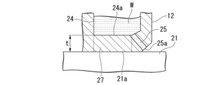
- the inner surface 21a of the mold 12 is cooled by the cooling water W contained in the cooling water cavity 24, which removes heat from the molten aluminum alloy M filling the hollow portion 21 of the mold 12 through the surface in contact with the inner surface 21a of the mold 12, forming a solidified shell on the surface of the molten aluminum alloy M.
- the cooling water W supplied through the cooling water supply pipe 26 is first stored in the cooling water cavity 24 to cool the inner surface 21a of the hollow portion 21 of the mold 12, and then the cooling water W in the cooling water cavity 24 is sprayed toward the aluminum alloy bar B from the cooling water spray passage 25.
- the supply of cooling water W to the cooling water cavity 24 and the spraying of cooling water W from the shower opening 25a of the cooling water spray passage 25 can each be controlled by a control signal from a control device (not shown).
- the cooling water cavity 24 is formed so that the inner bottom surface 24a near the hollow portion 21 of the mold 12 is parallel to the inner peripheral surface 21a of the hollow portion 21 of the mold 12.
- parallel in this context also includes cases where the inner peripheral surface 21a of the hollow portion 21 of the mold 12 is formed at an elevation angle of 0° to 3° relative to the inner bottom surface 24a of the cooling water cavity 24, i.e., where the inner bottom surface 24a is inclined from 0° to 3° relative to the inner peripheral surface 21a.
- the cooling wall portion 27 of the mold 12 which is the portion where the inner bottom surface 24a of the cooling water cavity 24 faces the inner surface 21a of the hollow portion 21 of the mold 12, is formed so that the heat flux value per unit area from the molten aluminum alloy M in the hollow portion 21 to the cooling water W in the cooling water cavity 24 is in the range of 10 x 105 W/ m2 or more and 50 x 105 W/ m2 or less.
- the mold 12 is formed so that the thickness t of the cooling wall 27 of the mold 12, i.e., the distance between the inner bottom surface 24a of the cooling water cavity 24 and the inner peripheral surface 21a of the hollow portion 21 of the mold 12, is within a range of, for example, 0.5 mm to 3.0 mm, and preferably 0.5 mm to 2.5 mm.
- the material for forming the mold 12 is selected so that the thermal conductivity of at least the cooling wall 27 of the mold 12 is within a range of 100 W/m ⁇ K to 400 W/m ⁇ K.
- the molten aluminum alloy M in the molten metal receiving section 11 is supplied from one end 12a of the mold 12, which is held so that the central axis C of the mold is nearly horizontal, via a refractory plate 13, and is forcibly cooled at the other end 12b of the mold 12 to become an aluminum alloy rod B.
- the aluminum alloy rod B is pulled out at a constant speed by a pull-out drive device (not shown) installed near the other end 12b of the mold 12, so that it is cast continuously to form a long aluminum alloy rod B.
- the pulled aluminum alloy rod B is then cut to the desired length, for example, by a synchronous cut-off machine (not shown).
- composition ratio of the cast aluminum alloy rod B can be confirmed, for example, by a method using a photoelectric emission spectrophotometric analyzer (example: Shimadzu PDA-5500, manufactured by Japan) as described in "JIS H 1305.”
- the difference in height between the liquid level of the molten aluminum alloy M stored in the molten metal receiving portion 11 and the upper inner peripheral surface 21a of the mold 12 is preferably 0 mm to 250 mm (more preferably 50 mm to 170 mm). By setting it in this range, the pressure of the molten aluminum alloy M supplied to the mold 12 and the lubricating oil and the gas produced by vaporizing the lubricating oil are appropriately balanced, resulting in stable castability.
- liquid lubricant vegetable oils, which are lubricating oils, can be used.
- vegetable oils which are lubricating oils
- examples include rapeseed oil, castor oil, and salad oil. These are preferred because they have a small negative impact on the environment.
- the lubricating oil supply rate is preferably 0.05 mL/min to 5 mL/min (more preferably 0.1 mL/min or more and 1 mL/min or less). If the supply rate is too low, there is a risk that the molten aluminum alloy M in the aluminum alloy rod B will not solidify and will leak from the mold 12 due to insufficient lubrication. If the supply rate is too high, the surplus may get mixed into the aluminum alloy rod B and cause internal defects.
- the casting speed which is the speed at which the aluminum alloy rod B is pulled out of the mold 12, is preferably 200 mm/min or more and 1500 mm/min or less (more preferably 400 mm/min or more and 1000 mm/min or less). This is because, at a casting speed within this range, the network structure of the crystals formed by casting becomes uniform and fine, which increases the resistance of the aluminum matrix to deformation at high temperatures and improves the high-temperature mechanical strength.
- the amount of cooling water sprayed from the shower opening 25a of the cooling water spray passage 25 is preferably 10 L/min or more and 50 L/min or less (more preferably 25 L/min or more and 40 L/min or less) per mold. If the amount of cooling water is less than this, the molten aluminum alloy M may not solidify and may leak from the mold 12. In addition, the surface of the cast aluminum alloy bar B may remelt, forming an uneven structure that may remain as an internal defect. On the other hand, if the amount of cooling water is more than this range, the mold 12 may lose too much heat, causing it to solidify midway.
- the average temperature of the molten aluminum alloy M flowing from the molten metal receiving portion 11 into the mold 12 is preferably, for example, 650°C or higher and 750°C or lower (more preferably 680°C or higher and 720°C or lower). If the temperature of the molten aluminum alloy M is too low, there is a risk that coarse crystals will form in the mold 12 or in front of it and will be incorporated into the aluminum alloy bar B as internal defects. On the other hand, if the temperature of the molten aluminum alloy M is too high, a large amount of hydrogen gas will be easily incorporated into the molten aluminum alloy M, which will be incorporated into the aluminum alloy bar B as porosity and may cause internal cavities.
- the heat flux value per unit area from the molten aluminum alloy M in the hollow portion 21 to the cooling water W in the cooling water cavity 24 in the cooling wall portion 27 of the mold 12 to a range of 10 x 10 5 W/m 2 or more and 50 x 10 5 W/m 2 or less, the occurrence of seizure of the aluminum alloy rod B can be prevented.
- the cooling wall 27 of the mold 12 receives heat from the molten aluminum alloy M and exchanges the heat by cooling it with the cooling water W contained in the cooling water cavity 24.
- the heat flux per unit area is expressed by the following formula (1) according to Fourier's law.
- the cooling wall portion 27 of the mold 12 is configured so that the heat flux value per unit area is 10 ⁇ 10 5 W/m 2 or more, thereby making it possible to prevent seizure of the cast aluminum alloy bar B. In addition, it is preferable that the heat flux value per unit area is 50 ⁇ 10 5 W/m 2 or less.
- the mold 12 may be formed so that the thickness t of the cooling wall portion 27 of the mold 12 is, for example, in the range of 0.5 mm or more and 3.0 mm or less.
- the thermal conductivity of at least the cooling wall portion 27 of the mold 12 may be set in the range of 100 W/m ⁇ K or more and 400 W/m ⁇ K or less.
- the above-mentioned horizontal continuous casting device 10 is used to continuously supply the molten aluminum alloy M stored in the molten metal receiving portion 11 into the hollow portion 21 from one end side 12a of the mold 12.
- cooling water W is supplied to the cooling water cavity 24, and a lubricating fluid, for example, lubricating oil, is supplied from the fluid supply pipe 22.
- the molten aluminum alloy M supplied into the hollow portion 21 is then cooled and solidified under conditions where the heat flux value per unit area in the cooling wall portion 27 is 10 ⁇ 105 W/ m2 or more, to cast the aluminum alloy bar B.
- the wall surface temperature of the cooling wall portion 27 of the mold 12 which is cooled by cooling water W, to 100° C. or less.
- the aluminum alloy rod B thus obtained is cooled and solidified under conditions where the heat flux value per unit area in the cooling wall 27 is 10 ⁇ 10 5 W/m 2 or more, thereby suppressing adhesion of reaction products, such as carbides, caused by contact between the lubricating oil gas and the molten aluminum alloy M. This makes it unnecessary to cut and remove carbides, etc., on the surface of the aluminum alloy rod B, and allows the aluminum alloy rod B to be produced with a high yield.
- the casting process for obtaining a cast product from the molten aluminum alloy M is not limited to the horizontal continuous casting method described above, and any known continuous casting method such as vertical continuous casting can be used.
- Vertical continuous casting methods are classified into the float method and the hot top method depending on the method of supplying the molten aluminum alloy M to the mold (casting mold 12), but the following will briefly explain the case where the hot top method is used.
- the casting equipment used in the hot top method is equipped with a mold, a molten metal receiving vessel (header), etc.
- the molten metal supplied to the molten metal receiving vessel passes through a spout and through the header, where the flow rate is adjusted, and enters a cylindrical mold that is installed almost horizontally, where it is forcibly cooled and a solidified shell is formed on the outer surface of the molten metal.
- Molds are generally made of metal components with good thermal conductivity, and have a hollow structure to allow the introduction of a coolant inside.
- the refrigerant to be used can be selected from those that are industrially available, but water is recommended from the viewpoint of ease of use.
- the mold used in this embodiment is appropriately selected from metals such as copper and aluminum, or graphite, from the viewpoint of heat transfer performance and durability at the contact point with the molten metal.
- the header is generally made of a refractory material and is installed on the upper side of the mold. There are no particular restrictions on the material and size of the header, and it can be appropriately selected depending on the composition range of the alloy to be cast and the dimensions of the cast product.
- the average cooling rate during casting can be selected, for example, from the range of 10°C/sec to 300°C/sec.
- the casting speed can be selected, for example, from the range of 200 to 600 mm/min.
- the homogenization heat treatment step is a step in which the aluminum alloy casting obtained by the casting step is subjected to heat treatment to homogenize microsegregation caused by solidification, precipitate supersaturated solid solution elements, and transform metastable phases into equilibrium phases.
- the aluminum alloy casting obtained in the casting process is subjected to homogenization heat treatment at a temperature of 370°C or higher and 560°C or lower for 4 to 10 hours.
- the aluminum alloy casting is homogenized sufficiently and solute atoms are sufficiently dissolved.
- the homogenization heat treatment process may be omitted.
- the forging process is a process in which an aluminum alloy casting is molded to a predetermined size to obtain a forging material, the obtained forging material is heated to a predetermined temperature, and then pressure is applied in a press to mold it into a die.
- the forging material is forged at a heating temperature of 450°C or higher and 560°C or lower to obtain a forged product (suspension arm component for an automobile).
- the forging start temperature of the forging material is 450°C or higher and 560°C or lower. If the start temperature is less than 450°C, there is a risk that the deformation resistance will be too high and sufficient processing will not be possible, while if it exceeds 560°C, there is a risk that defects such as forging cracks and eutectic melting will easily occur. It is also more preferable that the material temperature of the forging material is in the range of 480°C or higher and 520°C or lower.
- the forging material preferably has an average grain size within its surface of 100 ⁇ m or less, and more preferably 80 ⁇ m or less.
- the forging material has an average grain size within its surface of, for example, 30 ⁇ m or more.
- the solution treatment process is a process in which the forged product obtained in the forging process is heated at a temperature of 500° C. or higher to cause a solution treatment, thereby relieving the distortion introduced into the cast product and causing the solute elements to form a solid solution.
- the forged product is subjected to solution treatment by, for example, holding the forged product at a treatment temperature of 530°C or higher and 560°C or lower for 0.3 to 5 hours, and preferably holding the forged product at a treatment temperature of 530°C or higher and 550°C or lower for 1 to 4 hours.
- the time for solution treatment may be 3 hours or less.
- the heating rate from room temperature to the above-mentioned treatment temperature is preferably 5.0°C/min or higher. If the treatment temperature is not sufficient, the solute elements may not be sufficiently dissolved. On the other hand, if the treatment temperature is too high, the solute elements may be more dissolved, but eutectic melting or recrystallization may easily occur.
- the heating rate is less than 5.0°C/min, Mg 2 Si may precipitate coarsely.
- the treatment temperature is less than 530°C, the solution treatment may not proceed and it may be difficult to achieve high strength by aging precipitation, so it is preferable to perform the treatment at 530°C or higher as described above.
- the quenching process is a process in which the forged product in the solid-solution state obtained in the solution treatment process is rapidly cooled to form a supersaturated solid solution.
- the water quenching process is performed by placing the forged product in a water tank that stores water (quenching water) and submerging the forged product.
- the water temperature in the water tank is preferably 20°C or higher and 60°C or lower.
- the forged product is preferably placed in the water tank for 5 seconds or higher and 60 seconds or lower after solution treatment so that all surfaces of the forged product are in contact with water.
- the submersion time of the forged product varies depending on the size of the casting, but is, for example, between more than 5 minutes and 40 minutes.
- the aging treatment process is a process in which the forged product is heated and held at a relatively low temperature to precipitate the elements that are supersaturated in solid solution, thereby imparting an appropriate hardness.
- the forged product after the quenching process is heated to a temperature of 170°C to 220°C and held at that temperature for 0.5 hours or more, 7.0 hours or less, preferably 4 hours or more, to perform aging treatment. If the heating temperature is less than 180°C or the holding time is less than 0.5 hours, the Mg2Si -based precipitates that improve the tensile strength may not grow sufficiently. On the other hand, if the treatment temperature exceeds 220°C, the Mg2Si -based precipitates may become too coarse to sufficiently improve the tensile strength.
- Hot trimming process In the hot trimming process, the forged product that has been subjected to the aging treatment process is hot trimmed at a material temperature exceeding 100°C and not exceeding 250°C.
- FIG. 7 is a diagram for explaining a manufacturing method of a suspension member according to one embodiment of the present invention, and is a plan view showing an example of the configuration of a forged product before a hot trimming process is performed.
- a burr (excess material) 70 is formed on the outer periphery of the forged product 100X before the hot trimming process is performed.
- the burr 70 is composed of the forging material that did not enter the groove or hole of the die used to form the suspension member 100 during the forging process.
- the burr 70 is formed on the outer periphery of the first arm portion 1, the second arm portion 2, the arm connecting portion 3, the wheel side connecting portion 4, the first vehicle body side connecting portion 5, and the second vehicle body side connecting portion 6 of the suspension member 100.
- the burr 70 is formed so as to surround these members in the x and y directions when the forged product 100X is viewed in a plan view from the z direction.
- the burrs 70 are trimmed (trimmed) while the forged product 100X is heated. In the hot trimming process, the burrs are removed from the forged product 100X to form the suspension member 100. When the burrs 70 are removed from the suspension member 100, the parting PL corresponding to the base of the burrs 70 becomes exposed.
- the material temperature in the hot trimming process is in the range of more than 100°C and less than 250°C, and the temperature is preferably 125°C or more, more preferably 150°C or more, and even more preferably 175°C or more.
- the method for manufacturing the suspension member according to this embodiment makes it possible to manufacture the suspension member according to the above embodiment. According to the above embodiment, it is possible to provide a suspension member that has excellent stress corrosion cracking resistance even when recrystallization is present near the parting line, and a suspension member. Furthermore, the suspension member according to this embodiment is capable of achieving both excellent stress corrosion cracking resistance and strength.
- the upper and/or lower limit values of the numerical ranges described in this specification can be arbitrarily combined to define a preferred range.
- the upper and lower limit values of the numerical ranges can be arbitrarily combined to define a preferred range
- the upper limit values of the numerical ranges can be arbitrarily combined to define a preferred range
- the lower limit values of the numerical ranges can be arbitrarily combined to define a preferred range.
- composition of the molten metal in the embodiment of the method for manufacturing a suspension member will be the alloy composition of the manufactured suspension member.
- Example 1 First, a molten aluminum alloy having the alloy composition shown in Table 1 as reference numeral 1 was prepared.
- the prepared molten aluminum alloy was used as the raw material, and a horizontal continuous casting device as described above was used to produce a continuously cast rod with a circular cross section and a diameter of 82 mm.
- the continuous cast bar was molded to a size that would fit the die used in the forging process to produce the forging material, which was then heated to 500°C and forged to produce the forged product.
- the average crystal grain size (average line length per crystal) of the forging material was measured according to JIS G0551:2020 Appendix A A.2 (cutting method) and found to be 65 ⁇ m.
- the forged product was heated to a temperature (material temperature) of 200°C and hot trimming was performed.
- a temperature material temperature
- hot trimming burrs were trimmed from the outer periphery of the forged product.
- Stress corrosion cracking test A C-ring was cut out from the bush portion 5 of the prepared suspension member along the dashed line indicated with the symbol CR in Fig. 2.
- a SCC test was carried out on the C-ring by applying a load of 90% of the 0.2% yield strength to the C-ring in accordance with the method of JIS H 8711:2000.
- Test solution Dichromate solution Boiling test test time: 80 hours
- Test piece C-ring test piece Stress magnitude applied: 80% of the tensile strength of 380 MPa was applied. After the test time (80 hours) had elapsed under the above conditions, the C-ring was visually inspected for the presence or absence of stress corrosion cracking. Note that the test solution means that the test was conducted by immersing the C-ring in a boiled dichromate solution.
- FIG. 8 is a plan view showing a schematic configuration for performing an SCC test in Example 1. As shown in Figure 8, a bolt 71 and a nut 72 were fastened to the C-ring C 50 , and a strain gauge 73 was attached to the apex.
- Test piece conforming to the international standard ASTM-R5 was taken from the bushing.
- the tensile strength of the test piece was measured by a method in accordance with JIS H 8711:2000.
- Figure 9 is a structural image obtained by analyzing an electron microscope image of a cross section at the midpoint of the bushing in the x direction (a cross section along the center line indicated by the dashed line in Figure 3) near the apex 51 of the bushing in the suspension member of Example 1, using electron backscatter diffraction diffraction. Numerous grain boundaries indicated by black solid lines can be seen in Figure 9.
- Figure 9 is an image of a surface perpendicular to the parting line of the bushing.
- surface S0 located on the outermost side in the -y direction of the bushing is indicated by a dashed line
- surface S300 located 300 ⁇ m deep in the +y direction from surface S0 is indicated by a dashed double-dot line.
- symbol E0 is the point on the grain boundary closest to the point located in the -y direction at the apex.
- symbol E300 in Figure 9 is a point on the grain boundary that is on plane S300 located 300 ⁇ m deep from plane S0 and passes through point E0.
- the line that passes through points E0 and E300 on the grain boundary has an angle ⁇ of 30° with respect to plane S0.
- the angle ⁇ is a plane perpendicular to the plane consisting of the parting line of the bushing part, and is the inclination with respect to a plane parallel to the cylindrical axis of the bushing part.
Landscapes
- Chemical & Material Sciences (AREA)
- Engineering & Computer Science (AREA)
- Mechanical Engineering (AREA)
- Materials Engineering (AREA)
- Metallurgy (AREA)
- Organic Chemistry (AREA)
- Physics & Mathematics (AREA)
- Thermal Sciences (AREA)
- Crystallography & Structural Chemistry (AREA)
- Forging (AREA)
- Vehicle Body Suspensions (AREA)
Abstract
L'invention concerne un élément de suspension constitué d'un alliage d'aluminium ayant une composition d'alliage comprenant : Cu : de 0,3 à 0,5 % en masse, Mg : de 0,65 à 1,05 % en masse, Si : de 0,9 à 1,25 % en masse, Mn : de 0,4 à 0,6 % en masse, Fe : de 0,15 à 0,30 % en masse, Cr : de 0,09 à 0,25 % en masse, Ti : de 0,01 à 0,05 % en masse, B : de 0,0010 à 0,0050 % en masse, et le complément étant étant constitué d'Al et d'impuretés inévitables. Dans un plan perpendiculaire à une surface d'une partie douille formée le long d'une ligne de séparation et parallèle à l'axe cylindrique de la partie douille, l'inclinaison des limites de grains cristallins est inférieure ou égale à 45°.
Priority Applications (1)
| Application Number | Priority Date | Filing Date | Title |
|---|---|---|---|
| CN202480024808.5A CN120936732A (zh) | 2023-12-28 | 2024-09-20 | 悬架构件及悬架构件的制造方法 |
Applications Claiming Priority (2)
| Application Number | Priority Date | Filing Date | Title |
|---|---|---|---|
| JP2023-222058 | 2023-12-28 | ||
| JP2023222058A JP2025104370A (ja) | 2023-12-28 | 2023-12-28 | サスペンション部材およびサスペンション部材の製造方法 |
Publications (1)
| Publication Number | Publication Date |
|---|---|
| WO2025141982A1 true WO2025141982A1 (fr) | 2025-07-03 |
Family
ID=96217292
Family Applications (1)
| Application Number | Title | Priority Date | Filing Date |
|---|---|---|---|
| PCT/JP2024/033685 Pending WO2025141982A1 (fr) | 2023-12-28 | 2024-09-20 | Élément de suspension et procédé de fabrication d'élément de suspension |
Country Status (3)
| Country | Link |
|---|---|
| JP (1) | JP2025104370A (fr) |
| CN (1) | CN120936732A (fr) |
| WO (1) | WO2025141982A1 (fr) |
Citations (3)
| Publication number | Priority date | Publication date | Assignee | Title |
|---|---|---|---|---|
| JP2004074978A (ja) * | 2002-08-21 | 2004-03-11 | Kobe Steel Ltd | 自動車用サスペンション部品およびその製造方法 |
| JP2008163445A (ja) * | 2006-03-31 | 2008-07-17 | Kobe Steel Ltd | 自動車足回り部品およびその製造方法 |
| JP2023094439A (ja) * | 2021-12-23 | 2023-07-05 | 株式会社レゾナック | アルミニウム合金鍛造品 |
-
2023
- 2023-12-28 JP JP2023222058A patent/JP2025104370A/ja active Pending
-
2024
- 2024-09-20 CN CN202480024808.5A patent/CN120936732A/zh active Pending
- 2024-09-20 WO PCT/JP2024/033685 patent/WO2025141982A1/fr active Pending
Patent Citations (3)
| Publication number | Priority date | Publication date | Assignee | Title |
|---|---|---|---|---|
| JP2004074978A (ja) * | 2002-08-21 | 2004-03-11 | Kobe Steel Ltd | 自動車用サスペンション部品およびその製造方法 |
| JP2008163445A (ja) * | 2006-03-31 | 2008-07-17 | Kobe Steel Ltd | 自動車足回り部品およびその製造方法 |
| JP2023094439A (ja) * | 2021-12-23 | 2023-07-05 | 株式会社レゾナック | アルミニウム合金鍛造品 |
Also Published As
| Publication number | Publication date |
|---|---|
| JP2025104370A (ja) | 2025-07-10 |
| CN120936732A (zh) | 2025-11-11 |
Similar Documents
| Publication | Publication Date | Title |
|---|---|---|
| JP5027844B2 (ja) | アルミニウム合金成形品の製造方法 | |
| JP7533745B2 (ja) | アルミニウム合金鍛造用素材、アルミニウム合金製鍛造品及びその製造方法 | |
| JP7533746B2 (ja) | アルミニウム合金鍛造用素材、アルミニウム合金製鍛造品及びその製造方法 | |
| JP7722174B2 (ja) | アルミニウム合金鍛造品 | |
| JP2023104587A (ja) | アルミニウム合金鍛造品及びその製造方法 | |
| JP4359231B2 (ja) | アルミニウム合金成形品の製造方法、およびアルミニウム合金成形品 | |
| JP7722172B2 (ja) | アルミニウム合金鍛造品 | |
| JP7533743B2 (ja) | アルミニウム合金鍛造用素材、アルミニウム合金鍛造品及びその製造方法 | |
| JP7840305B2 (ja) | アルミニウム合金製鍛造品の製造方法 | |
| JP2024093687A (ja) | アルミニウム合金鍛造品及びその製造方法 | |
| JP2024085798A (ja) | アルミニウム合金製鍛造品及びその製造方法 | |
| WO2025141982A1 (fr) | Élément de suspension et procédé de fabrication d'élément de suspension | |
| JP2023161784A (ja) | アルミニウム合金鍛造品及びその製造方法 | |
| JP7750334B2 (ja) | アルミニウム合金鋳造品、アルミニウム合金鍛造品及びその製造方法 | |
| WO2025169601A1 (fr) | Matériau pour forgeage d'alliage d'aluminium, produit forgé en alliage d'aluminium et son procédé de fabrication | |
| JP7840306B2 (ja) | アルミニウム合金製鍛造品の製造方法 | |
| JP2024085792A (ja) | アルミニウム合金製鍛造品及びその製造方法 | |
| JP2024085797A (ja) | アルミニウム合金製鍛造品及びその製造方法 | |
| JP2025000887A (ja) | アルミニウム合金鍛造用素材、アルミニウム合金製鍛造品及びその製造方法 | |
| JP2024085793A (ja) | アルミニウム合金製鍛造品及びその製造方法 | |
| JP2025000890A (ja) | アルミニウム合金鍛造用素材、アルミニウム合金製鍛造品及びその製造方法 | |
| JP2024093725A (ja) | アルミニウム合金鍛造品及びその製造方法 | |
| WO2025142061A1 (fr) | Élément de bras de suspension et procédé permettant de fabriquer un élément de bras de suspension | |
| WO2025169598A1 (fr) | Matériau pour forgeage d'alliage d'aluminium, produit forgé en alliage d'aluminium et son procédé de fabrication | |
| WO2025173376A1 (fr) | Matériau pour le forgeage d'alliage d'aluminium, produit forgé en alliage d'aluminium et procédé de fabrication associé |
Legal Events
| Date | Code | Title | Description |
|---|---|---|---|
| 121 | Ep: the epo has been informed by wipo that ep was designated in this application |
Ref document number: 24911876 Country of ref document: EP Kind code of ref document: A1 |