WO2025142995A1 - Dispositif et procédé de poinçonnage - Google Patents
Dispositif et procédé de poinçonnage Download PDFInfo
- Publication number
- WO2025142995A1 WO2025142995A1 PCT/JP2024/045851 JP2024045851W WO2025142995A1 WO 2025142995 A1 WO2025142995 A1 WO 2025142995A1 JP 2024045851 W JP2024045851 W JP 2024045851W WO 2025142995 A1 WO2025142995 A1 WO 2025142995A1
- Authority
- WO
- WIPO (PCT)
- Prior art keywords
- punching
- stage
- stages
- punch
- punches
- Prior art date
- Legal status (The legal status is an assumption and is not a legal conclusion. Google has not performed a legal analysis and makes no representation as to the accuracy of the status listed.)
- Pending
Links
Images


Classifications
-
- B—PERFORMING OPERATIONS; TRANSPORTING
- B21—MECHANICAL METAL-WORKING WITHOUT ESSENTIALLY REMOVING MATERIAL; PUNCHING METAL
- B21D—WORKING OR PROCESSING OF SHEET METAL OR METAL TUBES, RODS OR PROFILES WITHOUT ESSENTIALLY REMOVING MATERIAL; PUNCHING METAL
- B21D28/00—Shaping by press-cutting; Perforating
- B21D28/02—Punching blanks or articles with or without obtaining scrap; Notching
-
- B—PERFORMING OPERATIONS; TRANSPORTING
- B30—PRESSES
- B30B—PRESSES IN GENERAL
- B30B13/00—Methods of pressing not special to the use of presses of any one of the preceding main groups
-
- H—ELECTRICITY
- H02—GENERATION; CONVERSION OR DISTRIBUTION OF ELECTRIC POWER
- H02K—DYNAMO-ELECTRIC MACHINES
- H02K15/00—Processes or apparatus specially adapted for manufacturing, assembling, maintaining or repairing of dynamo-electric machines
- H02K15/02—Processes or apparatus specially adapted for manufacturing, assembling, maintaining or repairing of dynamo-electric machines of stator or rotor bodies
- H02K15/021—Magnetic cores
- H02K15/027—Punching the cores
Definitions
- the present invention relates to a punching device and method for punching out core pieces used in laminated cores for rotating electrical machines.
- a conventional punching device is one equipped with multiple stages, as shown in Patent Document 1, for example.
- the multiple stages are straddled by a steel plate, and punches are sequentially performed on the steel plate with a punch to form an iron core piece in the final stage.
- This punching device is designed so that the punch with the heaviest punching load presses the steel plate at the earliest possible timing, since quality would be reduced if punching was performed simultaneously on all stages.
- the problem to be solved is the decrease in machining accuracy of the core pieces.
- the present invention provides a punching device that includes punches provided for a plurality of stages across which a common steel plate is positioned and which punch the steel plate in sequence to form iron core pieces, the punches of the plurality of stages descend together to punch the steel plate, and the punches have a tip position in the punching direction such that the punching timing of the stage with the largest punching load is delayed relative to the punching timing of at least one other stage.
- the present invention provides a punching method in which a common steel plate is placed across multiple stages in which punching is performed sequentially on the steel plate to form iron core pieces, and punches of the multiple stages are lowered together to punch the steel plate in the multiple stages, and the punch timing of the punch in the stage with the largest punching load is delayed relative to at least one other stage.
- the present invention can improve the machining accuracy of the core pieces.
- FIG. 1 is a schematic diagram of a punching device according to a first embodiment of the present invention.
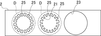
- FIG. 2 is a plan view of a steel plate punched by the punching apparatus of FIG.
- FIG. 3 is a schematic diagram of an upper die of a punching device according to a first modified example of the first embodiment.
- FIG. 4 is a schematic diagram of an upper die of a punching device according to a second modified example of the first embodiment, as viewed from the feeding direction of the steel plate.
- FIG. 5 is a schematic diagram of a punching device according to the second embodiment.
- FIG. 6 is a plan view of a steel plate punched by the punching device of FIG.
- FIG. 7 is a schematic cross-sectional view of a punching device according to a modified example of the second embodiment.
- the punching device 1 is provided with punches 9, 11, 13, 41, 43, and 45 on multiple stages 3, 5, 7, 35, 37, and 39, respectively, across which a common steel plate 2 is positioned and which sequentially punch the steel plate 2 to form the iron core pieces 27 and 53.
- the punches 9, 11, 13, 41, 43, and 45 on the multiple stages 3, 5, 7, 35, 37, and 39 all descend to punch the steel plate 2.
- the punches 9, 11, 13, 41, 43, and 45 have tip positions in the punching direction where the punching timing on stage 7, where the punching load is maximum, is delayed relative to the punching timing on at least one of the other stages 3, 5, 35, 37, and 39.
- punches 9, 11, 13, 41, 43, and 45 have a slower punching timing in stage 7, where the punching load is the largest, compared to all other stages 3, 5, 35, 37, and 39.
- the stages may include a first stage 3, a second stage 5, and a third stage 7.
- the first stage 3 punches out the inner circumference 21 of the core piece 27.
- the second stage 5 punches out the outer circumference 23 of the core piece 27.
- the third stage 7 punches out the punched portion 25 of the core piece 27.
- the punching load of the third stage 7 is relatively large compared to the first and second stages 3 and 5. In this case, the tip position of the third stage 7 in the punching direction is set so that the punching timing is later than the punches 9 and 11 of the first and second stages 3 and 5.
- the punching device 1 may include at least one other stage 3, 5, 35, 37, 39 upstream and downstream of stage 7, where the punching load is maximum.
- the punching method involves placing the steel plate 2 across multiple stages 3, 5, 7, 35, 37, and 39, which sequentially punch the common steel plate 2 to form the iron core pieces 27 and 53, and punches 9, 11, 13, 41, 43, and 45 of the multiple stages 3, 5, 7, 35, 37, and 39 all descending to punch the steel plate 2 at the multiple stages 3, 5, 7, 35, 37, and 39.
- the punching timing of punch 13 is delayed relative to at least one of the other stages 3, 5, 35, 37, and 39.
- FIG. 1 is a schematic diagram of a punching device according to a first embodiment of the present invention.
- Fig. 2 is a plan view of a steel plate punched by the punching device of Fig. 1.
- the punching device 1 in FIG. 1 punches out core pieces 27 to be used in a motor core, which is a laminated core for a rotating electrical machine.
- the motor core in this embodiment is a stator core, but it may also be a rotor core.
- the punching device 1 includes an upper die 15 and a lower die 17.
- the upper die 15 and the lower die 17 include first, second, and third stages 3, 5, and 7, which are arranged along the feed direction of the steel plate 2.
- the stages represent the individual steps when the iron core piece 27 is formed in multiple steps.
- the first to third stages 3, 5, and 7 are positioned across a common steel plate 2, and punching of the steel plate 2 is performed sequentially in the feed direction to form the core pieces 27. These first to third stages 3, 5, and 7 are equipped with punches 9, 11, and 13, respectively.
- Punches 9, 11, and 13 are attached to upper die 15. Punches 9, 11, and 13 are configured to descend together with upper die 15. This descent causes a stripper (not shown) to press the steel sheet 2 against lower die 17 in advance, and upper die 15 descends further relative to lower die 17. As a result, punches 9, 11, and 13 of first to third stages 3, 5, and 7 descend further to punch out the steel sheet 2.
- the lower die 17 has a die 17a corresponding to the second stage 5.
- the die 17a is provided with a squeeze ring 17c connected to the die body 17b.
- the die body 17b cooperates with the punch 11 to punch out the core pieces 27, and the squeeze ring 17c applies lateral pressure to the punched core pieces 27 to hold them in place. Therefore, in the second stage 5, the core pieces 27 punched out by the punch 11 and die 17a are sequentially held and stacked in the die 17a.
- the lower die 17 is provided with dies corresponding to the first and third stages 3 and 7, although these are not shown.
- the first stage 3 punches the inner circumference of the core piece 27
- the second stage 5 punches the outer circumference of the core piece 27
- the third stage 7 punches the shape of the core piece 27.
- stage settings are optional. Other stages can be added for forming crimped parts using uneven surfaces, applying adhesive, etc.
- the inner circumference punching in the first stage 3 punches out the inner circumference circle 21 of the core piece 27.
- the outer circumference punching in the second stage 5 punches out the outer circumference circle 23 of the core piece 27.
- the shape punching in the third stage 7 punches out the slot portion 25 of the core piece 27. Note that in Figure 2, the part that will become the outer circumference circle 23 of the core piece 27 is shown by the dashed line D. Also, the hole after the outer circumference punching of the core piece 27 is shown as the outer circumference circle 23.
- the inner circumference circle 21 and the outer circumference circle 23 are punched concentrically to form the iron core piece 27, and the slots 25 are arranged at equal intervals in the circumferential direction of the inner circumference circle 21 and the outer circumference circle 23.
- the slots 25 are arranged concentrically with respect to the inner circumference circle 21 and the outer circumference circle 23.
- the punching load of the third stage 7 is relatively large compared to the first and second stages 3 and 5. For this reason, the tip positions of the punches 9, 11, and 13 are set so that the punching timing of the third stage 7, which has the largest punching load, is delayed compared to all the other stages 3 and 5.
- the punching timing can be set so that the third stage 7, which has the largest punching load, is delayed relative to at least one of the other stages 3 or 5.
- the punching timing can be set so that the third stage 7 is slower than the first stage 3 and the second stage 5 is faster than the third stage 7, or the third stage 7 is slower than the second stage 5 and the first stage 3 is faster than the third stage 7.
- the punching load is the load required for punching by the press, and depends on the machining circumference of punches 9, 11, and 13.
- the machining circumference is the outer perimeter dimension of the cross section of each punch. The longer the machining circumference, the larger the punching load.
- the machining circumference of the punch 13 in the third stage 7 is the sum of the punches that punch each slot portion 25, and is longer than the first and second stages 3 and 5. Therefore, the punching load in the third stage 7 is the largest among the first to third stages 3, 5, and 7.
- the machining circumference of the punch 13 in the third stage 7 may be relatively shorter than the punches 9 and 11 in the first and second stages 3 and 5. For this reason, the punching load of the punch 13 is not necessarily the greatest in the third stage 7. The same applies when other stages are added.
- the heights of the tip positions of punches 9, 11, and 13 from the upper die 15 are in the following relationship: height H0 of tip position of punch 9 > height H1 of tip position of punch 11 > height H2 of tip position of punch 13.
- the protruding length of punch 13 in the third stage 7 from the upper die 15 is shorter than the protruding length of punches 9 and 11 in the first and second stages 3 and 5, and the protruding length of punch 11 in the second stage 5 is shorter than the protruding length of punch 9 in the first stage 3.
- the timing of punching the steel sheet 1 by the lowering of the upper die 15 is the order of punches 9, 11, and 13 on the first, second, and third stages 3, 5, and 7.
- the timing of punching by the punch 13 in the third stage 7 may be intermediate among the first to third stages 3, 5, and 7.
- [Punching method] In the punching method of this embodiment, first, the steel sheet 2 is fed and placed between the upper die 15 and the lower die 17. At this time, the steel sheet 2 is placed across the multiple stages 3, 5, and 7. In the first punching, the leading end of the steel sheet 2 in the feed direction is placed on the third stage 7, and in the second punching, the steel sheet 2 is placed across the first stage 3 and the third stage 7. Then, in the third punching and thereafter, the steel sheet 2 is placed across the first to third stages 3, 5, and 7.
- the timing of this punching is as follows: punches 9, 11, and 13 in the first, second, and third stages 3, 5, and 7. Note that in the second punching, the order is punches 9 and 13 in the first and third stages 3 and 7.
- punch 9 which has the smallest punching load, punches the steel plate 2 first, followed by punch 11, and punch 13, which has the largest punching load, punches last.
- punch 9 which has the smallest punching load, punches first, followed by punch 13, which has the largest punching load.
- the timing of punching by punch 13 in the third stage 7 may be intermediate among the first to third stages 3, 5, and 7, as described above.
- the third stage 7 which has the largest punching load, has a slower punching timing than the other first and second stages 3 and 5.
- the steel plate 2 can be positioned by the punches 9 and 11 of the first and second stages 3 and 5 that have previously performed punching, while punching can be performed by the punch 13 of the third stage 7, which has the largest punching load. This makes it possible to improve the processing accuracy of punching in the third stage 7 and suppress distortion of the steel plate 2 during punching in the third stage 7, thereby more reliably improving the processing accuracy of the core pieces 27.
- punching in the first and second stages 3 and 5, which are subsequent processes in the feed direction can be performed on steel plate 2 with reduced distortion, so the machining accuracy of core piece 27 can be improved more reliably.
- the punching timing of the punch 11 of the second stage 5 which has a relatively high punching load, is delayed relative to the punching timing of the punch 9 of the first stage 3, which has a relatively low punching load.
- the processing accuracy of the punching in the first stage 3, which is performed first can be improved. Also, while the steel plate 2 is positioned by the punch 9 in the first stage 3, which has performed the punching first, punching can be performed by the punch 11 in the second stage 5, which has a relatively large punching load. This makes it possible to more reliably improve the processing accuracy of the core pieces 27 and suppress distortion of the steel plate 2 during punching in the first stage 3. Therefore, it is possible to more reliably improve the processing accuracy of the core pieces 27. Also, even if the punching timing of the first and third stages 3 and 7 or the punching timing of the second and third stages 5 and 7 are simultaneous, the processing accuracy of the core pieces 27 can be improved.
- FIG. 3 is a schematic diagram of an upper die of a punching device according to a first modified example of the first embodiment.
- the height of the tip position is varied within the punch 13 of the third stage 7.
- punch 13 is configured as a punch that punches out slot portion 25, and has multiple punch portions 13a that correspond to slot portion 25. These punch portions 13a have different tip heights. Punch portions 13a are arranged along the circumferential direction, and accordingly, punching timing of punch 13 differs in the circumferential direction.
- FIG. 4 is a schematic diagram of an upper die of a punching device according to a second modified example of the first embodiment, as viewed from the feeding direction of the steel plate.
- the inner circumference circle 21, the outer circumference circle 23, and the slot portion 25 are punched out using punches 9, 11, and 13 in a single row of the first to third stages 3, 5, and 7, but in modification 2, punching is performed simultaneously in multiple rows.
- the first, second, and third stages 3, 5, and 7, each having the same processing order are provided in multiple rows, for example two rows, in the width direction of the steel plate 2.
- the mutual tip positions of the punches 9, 11, or 13 of the same stage 3, 5, or 7 may be set not only to be the same, but also to be different.
- the relationship between the tip positions of the punches 9, 11, and 13 of the different stages 3, 5, and 7 may be set by the average length of the punches 9, 11, or 13 of the same stage 3, 5, or 7, the length of the longest punch, or the length of the shortest punch.
- the punches 9 of the first stage 3 are arranged in two rows in the width direction of the steel plate 2, and the tip positions of the punches 9 of the same stage 3 differ depending on their length.
- the tip position of the punch 9 as the first stage 3 can be set using any of the following lengths: the average value of the tip positions of the punches 9 of the same stage 3 in two rows, the longest length, or the shortest length.
- the tip positions of the punches 9, 11, and 13 can be set arbitrarily as long as the relationship is maintained.
- the punching device 1 of Example 2 has rotor core stages 35, 37, and 39 arranged in succession upstream of stator core stages 3, 5, and 7 in the feed direction of the steel plate 2, as shown in Figures 5 and 6.
- the configuration has at least one other stage 3, 5, 35, 37, and 39 upstream and downstream of the third stage 7 of the stator core, where the punching load is maximum.
- rotor core stages 35, 37, and 39 are located upstream of the third stage 7 of the stator core
- stator core stages 3 and 5 are located downstream of the third stage 7 of the stator core.
- the punching device 1 of this embodiment has an upper die 15A equipped with punches 9, 11, and 13 configured in the same manner as in embodiment 1, and a lower die 17A equipped with a die 17a, for the stages 3, 5, and 7 of the stator core.
- stages 35, 37, and 39 of the rotor core there is an upper die 15B equipped with punches 41, 43, and 45, and a lower die 17B equipped with a die 17a.
- the upper die 15B is separated so as to operate separately from the upper die 15A.
- the lower die 17B is also separated from the lower die 17A and provided separately.
- the first stage 35 punches the inner circumference
- the second stage 37 punches the outer circumference
- the third stage 39 punches the shape.
- the inner circumference punching of the first stage 35 of the rotor core punches out the inner circumference circle 47 of the iron core piece 53.
- the outer circumference punching of the second stage 37 punches out the outer circumference circle 49 of the iron core piece 53.
- the shape punching of the third stage 39 punches out the magnet insertion hole 51 of the iron core piece 53.
- the inner circumference circle 47 and the outer circumference circle 49 are punched concentrically to form the iron core piece 53, and the magnet insertion holes 51 are arranged at equal intervals in the circumferential direction.
- the magnet insertion holes 51 are arranged concentrically with the inner circumference circle 47 and the outer circumference circle 49.
- FIG. 6 the portion that will become the outer circumferential circle 23 of the stator core piece 27 is shown by dashed line D1, and the portion that will become the outer circumferential circle 49 of the rotor core piece 53 is shown by dashed line D2.
- the holes that remain after punching out the outer circumferential circle of the core pieces 27 and 53 are shown as the outer circumferential circles 23 and 49.
- the punching timing of the punches 9, 11, and 13 of the first to third stages 3, 5, and 7 of the stator core and the punches 41, 43, and 45 of the first to third stages 35, 37, and 39 of the rotor core is different between at least two stages, and the punching tip positions are set in the punching direction.
- the punching load of the punch 13 of the third stage 7 of the stator core is the highest. For this reason, of all the punches for the iron core pieces 27 and 53 of the stator core and rotor core, the punch 13 is set to the lowest tip position height H2.
- the punches 9 and 11 of the first and second stages 3 and 5 of the stator core have the heights of the tip positions of the punches 9 and 11 set to H0 and H1, similar to Example 1.
- the punches 41, 43, and 45 of the first to third stages 35, 37, and 39 of the rotor core have tip heights set to H0, H1, and H0, respectively.
- the punch 43 in the second stage 37 which has the largest punching load, has its tip position set in the punching direction so that its punching timing differs from that of the other punches 41 and 45 in the first and third stages 35 and 39.
- the steel sheet 2 is first fed and placed between the upper die 15B and the lower die 17B.
- the leading end of the steel sheet 2 in the feed direction is placed in the third stage 39 of the rotor core
- the steel sheet 2 is placed across the first stage 35 to the third stage 39 of the rotor core.
- the steel sheet 2 is placed across the first to third stages 35, 37, and 39 of the rotor core.
- the steel sheet 2 sequentially straddles the first to third stages 3, 5, and 7 of the stator core during the fourth to sixth punchings. After that, the steel sheet 2 is placed across all the stages of the rotor core and the stator core.
- the timing of the punching process is such that punches 41 and 45 punch the rotor core first at the same time, followed by punch 43, depending on the tip position setting.
- punches 41 and 45 which have a relatively low punching load, perform punching first
- punch 43 which has a relatively high and maximum punching load, performs punching later.
- the stator core is punched in the same manner as in Example 1, with punches 9, 11, and 13 in that order.
- punch 9 of the stator core is punched simultaneously with punches 41 and 45 of the rotor core
- punch 11 of the stator core is punched simultaneously with punch 43 of the rotor core
- punch 13 of the stator core is punched.
- the punching timing of the rotor core iron piece 53 is delayed with respect to at least one of the stages 41 and 45 in the punch 43.
- the machining precision of the iron core pieces 53 of the rotor core can be improved more reliably.
- the second embodiment can achieve the same effects as the first embodiment.
- FIG. 7 is a schematic cross-sectional view of a punching device according to a modified example of the second embodiment.
- the punching device 1 As shown in FIG. 7, the punching device 1 according to the modified example is provided with punches 41, 43, 45, 9, 11, and 13 for the rotor core and the stator core in a common upper die 15. Accordingly, a die 17a is provided in a common lower die 17 corresponding to the second stages 37 and 5 of the rotor core and the stator core.
Landscapes
- Engineering & Computer Science (AREA)
- Mechanical Engineering (AREA)
- Manufacturing & Machinery (AREA)
- Power Engineering (AREA)
- Manufacture Of Motors, Generators (AREA)
Abstract
L'invention concerne un dispositif de poinçonnage apte à poinçonner dans lequel la rondeur d'une pièce de noyau de fer est prise en compte. Dans la présente invention, des poinçons 9, 11 et 13 sont ménagés en correspondance d'une pluralité de platines 3, 5 et 7 sur lesquelles une plaque d'acier 2 commune est agencée et qui réalisent en séquence un poinçonnage de la plaque d'acier 2 pour former des pièces de noyau de fer 27, les poinçons 9, 11 et 13 de la pluralité de platines 3, 5 et 7 sont abaissés ensemble pour poinçonner la plaque d'acier 2, et la position de pointe du poinçon 13 dans la direction de poinçonnage est établie de telle sorte que l'instant de poinçonnage de celui-ci soit ultérieure à celle des poinçons 9 et 11.
Applications Claiming Priority (2)
| Application Number | Priority Date | Filing Date | Title |
|---|---|---|---|
| JP2023-223695 | 2023-12-28 | ||
| JP2023223695 | 2023-12-28 |
Publications (1)
| Publication Number | Publication Date |
|---|---|
| WO2025142995A1 true WO2025142995A1 (fr) | 2025-07-03 |
Family
ID=96219149
Family Applications (1)
| Application Number | Title | Priority Date | Filing Date |
|---|---|---|---|
| PCT/JP2024/045851 Pending WO2025142995A1 (fr) | 2023-12-28 | 2024-12-25 | Dispositif et procédé de poinçonnage |
Country Status (1)
| Country | Link |
|---|---|
| WO (1) | WO2025142995A1 (fr) |
Citations (6)
| Publication number | Priority date | Publication date | Assignee | Title |
|---|---|---|---|---|
| JP2002325402A (ja) * | 2001-04-27 | 2002-11-08 | Kuroda Precision Ind Ltd | 積層鉄心の製造方法及び装置 |
| JP2005081413A (ja) * | 2003-09-10 | 2005-03-31 | Aisin Aw Co Ltd | プレス加工装置における打ち抜き用雄型 |
| WO2009096257A1 (fr) * | 2008-02-01 | 2009-08-06 | Sumiden Electronics, Ltd. | Dispositif de presse |
| CN205651705U (zh) * | 2016-05-06 | 2016-10-19 | 深圳市铭利达精密机械有限公司 | 一种冲头组件及油压机 |
| JP2018069251A (ja) * | 2016-10-24 | 2018-05-10 | Shマテリアル株式会社 | 打ち抜き加工用金型、打抜き加工方法、およびリードフレームの製造方法 |
| CN213530405U (zh) * | 2020-10-28 | 2021-06-25 | 深圳市诚瑞丰科技股份有限公司 | 一种密集孔板件的易脱料精密冲压模具 |
-
2024
- 2024-12-25 WO PCT/JP2024/045851 patent/WO2025142995A1/fr active Pending
Patent Citations (6)
| Publication number | Priority date | Publication date | Assignee | Title |
|---|---|---|---|---|
| JP2002325402A (ja) * | 2001-04-27 | 2002-11-08 | Kuroda Precision Ind Ltd | 積層鉄心の製造方法及び装置 |
| JP2005081413A (ja) * | 2003-09-10 | 2005-03-31 | Aisin Aw Co Ltd | プレス加工装置における打ち抜き用雄型 |
| WO2009096257A1 (fr) * | 2008-02-01 | 2009-08-06 | Sumiden Electronics, Ltd. | Dispositif de presse |
| CN205651705U (zh) * | 2016-05-06 | 2016-10-19 | 深圳市铭利达精密机械有限公司 | 一种冲头组件及油压机 |
| JP2018069251A (ja) * | 2016-10-24 | 2018-05-10 | Shマテリアル株式会社 | 打ち抜き加工用金型、打抜き加工方法、およびリードフレームの製造方法 |
| CN213530405U (zh) * | 2020-10-28 | 2021-06-25 | 深圳市诚瑞丰科技股份有限公司 | 一种密集孔板件的易脱料精密冲压模具 |
Similar Documents
| Publication | Publication Date | Title |
|---|---|---|
| JP5352445B2 (ja) | 積層鉄心の製造方法 | |
| JP6315537B2 (ja) | 積層鉄心の製造方法及びその製造装置 | |
| JP5875746B2 (ja) | 固定子鉄心の製造方法 | |
| US10298103B2 (en) | Manufacturing method of laminated core and manufacturing device of laminated core | |
| JP2010213505A (ja) | 分割鉄心片の製造方法及びこれを用いた固定子鉄心 | |
| JP3149217B2 (ja) | 積層鉄心用薄板の多列打抜き方法 | |
| KR101867186B1 (ko) | 쇼바씰 제조용 프레스 공정의 소재두께 보정방법 및 그 금형 | |
| JP4898240B2 (ja) | 鉄心片の製造方法 | |
| JP2015188934A (ja) | 薄鋼板の打抜き加工方法及び打抜き加工金型 | |
| WO2025142995A1 (fr) | Dispositif et procédé de poinçonnage | |
| US20160243605A1 (en) | Die apparatus and manufacturing method of metal product using die apparatus | |
| JP7136821B2 (ja) | 順送プレス加工方法 | |
| JP4749748B2 (ja) | 鉄心の打ち抜き製造方法 | |
| JP7733528B2 (ja) | 順送り金型装置および積層鉄心の製造方法 | |
| JP2010093997A (ja) | 積層鉄心の製造方法及び金型装置 | |
| JP4115765B2 (ja) | 押圧支持リングを設けた金型装置 | |
| JP4989877B2 (ja) | 回転子積層鉄心の製造方法 | |
| JPS606299A (ja) | 順送り打ち抜き方法 | |
| JP2011061958A (ja) | 積層鉄心の製造方法及びこれを用いて製造した積層鉄心 | |
| JP5462675B2 (ja) | 積層鉄心の製造方法 | |
| KR100964023B1 (ko) | 적층 코아 제조 장치의 에어 갭 다이 및 이를 채용한 적층코아 제조 장치 | |
| JP2001190048A (ja) | 鉄心打抜き方法 | |
| KR100522534B1 (ko) | 적층 코아 제조장치 및 그 제조방법 | |
| WO2019202930A1 (fr) | Dispositif de fabrication d'un produit pressé | |
| WO2018066518A1 (fr) | Procédé de fabrication d'une pièce de noyau |
Legal Events
| Date | Code | Title | Description |
|---|---|---|---|
| 121 | Ep: the epo has been informed by wipo that ep was designated in this application |
Ref document number: 24912881 Country of ref document: EP Kind code of ref document: A1 |
|
| ENP | Entry into the national phase |
Ref document number: 2025567176 Country of ref document: JP Kind code of ref document: A |
|
| WWE | Wipo information: entry into national phase |
Ref document number: 2025567176 Country of ref document: JP |