WO2025142995A1 - 打ち抜き装置及び方法 - Google Patents
打ち抜き装置及び方法 Download PDFInfo
- Publication number
- WO2025142995A1 WO2025142995A1 PCT/JP2024/045851 JP2024045851W WO2025142995A1 WO 2025142995 A1 WO2025142995 A1 WO 2025142995A1 JP 2024045851 W JP2024045851 W JP 2024045851W WO 2025142995 A1 WO2025142995 A1 WO 2025142995A1
- Authority
- WO
- WIPO (PCT)
- Prior art keywords
- punching
- stage
- stages
- punch
- punches
- Prior art date
- Legal status (The legal status is an assumption and is not a legal conclusion. Google has not performed a legal analysis and makes no representation as to the accuracy of the status listed.)
- Pending
Links
Images


Classifications
-
- B—PERFORMING OPERATIONS; TRANSPORTING
- B21—MECHANICAL METAL-WORKING WITHOUT ESSENTIALLY REMOVING MATERIAL; PUNCHING METAL
- B21D—WORKING OR PROCESSING OF SHEET METAL OR METAL TUBES, RODS OR PROFILES WITHOUT ESSENTIALLY REMOVING MATERIAL; PUNCHING METAL
- B21D28/00—Shaping by press-cutting; Perforating
- B21D28/02—Punching blanks or articles with or without obtaining scrap; Notching
-
- B—PERFORMING OPERATIONS; TRANSPORTING
- B30—PRESSES
- B30B—PRESSES IN GENERAL
- B30B13/00—Methods of pressing not special to the use of presses of any one of the preceding main groups
-
- H—ELECTRICITY
- H02—GENERATION; CONVERSION OR DISTRIBUTION OF ELECTRIC POWER
- H02K—DYNAMO-ELECTRIC MACHINES
- H02K15/00—Processes or apparatus specially adapted for manufacturing, assembling, maintaining or repairing of dynamo-electric machines
- H02K15/02—Processes or apparatus specially adapted for manufacturing, assembling, maintaining or repairing of dynamo-electric machines of stator or rotor bodies
- H02K15/021—Magnetic cores
- H02K15/027—Punching the cores
Definitions
- the present invention relates to a punching device and method for punching out core pieces used in laminated cores for rotating electrical machines.
- a conventional punching device is one equipped with multiple stages, as shown in Patent Document 1, for example.
- the multiple stages are straddled by a steel plate, and punches are sequentially performed on the steel plate with a punch to form an iron core piece in the final stage.
- This punching device is designed so that the punch with the heaviest punching load presses the steel plate at the earliest possible timing, since quality would be reduced if punching was performed simultaneously on all stages.
- the problem to be solved is the decrease in machining accuracy of the core pieces.
- the present invention provides a punching device that includes punches provided for a plurality of stages across which a common steel plate is positioned and which punch the steel plate in sequence to form iron core pieces, the punches of the plurality of stages descend together to punch the steel plate, and the punches have a tip position in the punching direction such that the punching timing of the stage with the largest punching load is delayed relative to the punching timing of at least one other stage.
- the present invention provides a punching method in which a common steel plate is placed across multiple stages in which punching is performed sequentially on the steel plate to form iron core pieces, and punches of the multiple stages are lowered together to punch the steel plate in the multiple stages, and the punch timing of the punch in the stage with the largest punching load is delayed relative to at least one other stage.
- the present invention can improve the machining accuracy of the core pieces.
- FIG. 1 is a schematic diagram of a punching device according to a first embodiment of the present invention.
- FIG. 2 is a plan view of a steel plate punched by the punching apparatus of FIG.
- FIG. 3 is a schematic diagram of an upper die of a punching device according to a first modified example of the first embodiment.
- FIG. 4 is a schematic diagram of an upper die of a punching device according to a second modified example of the first embodiment, as viewed from the feeding direction of the steel plate.
- FIG. 5 is a schematic diagram of a punching device according to the second embodiment.
- FIG. 6 is a plan view of a steel plate punched by the punching device of FIG.
- FIG. 7 is a schematic cross-sectional view of a punching device according to a modified example of the second embodiment.
- the punching device 1 is provided with punches 9, 11, 13, 41, 43, and 45 on multiple stages 3, 5, 7, 35, 37, and 39, respectively, across which a common steel plate 2 is positioned and which sequentially punch the steel plate 2 to form the iron core pieces 27 and 53.
- the punches 9, 11, 13, 41, 43, and 45 on the multiple stages 3, 5, 7, 35, 37, and 39 all descend to punch the steel plate 2.
- the punches 9, 11, 13, 41, 43, and 45 have tip positions in the punching direction where the punching timing on stage 7, where the punching load is maximum, is delayed relative to the punching timing on at least one of the other stages 3, 5, 35, 37, and 39.
- punches 9, 11, 13, 41, 43, and 45 have a slower punching timing in stage 7, where the punching load is the largest, compared to all other stages 3, 5, 35, 37, and 39.
- the stages may include a first stage 3, a second stage 5, and a third stage 7.
- the first stage 3 punches out the inner circumference 21 of the core piece 27.
- the second stage 5 punches out the outer circumference 23 of the core piece 27.
- the third stage 7 punches out the punched portion 25 of the core piece 27.
- the punching load of the third stage 7 is relatively large compared to the first and second stages 3 and 5. In this case, the tip position of the third stage 7 in the punching direction is set so that the punching timing is later than the punches 9 and 11 of the first and second stages 3 and 5.
- the punching device 1 may include at least one other stage 3, 5, 35, 37, 39 upstream and downstream of stage 7, where the punching load is maximum.
- the punching method involves placing the steel plate 2 across multiple stages 3, 5, 7, 35, 37, and 39, which sequentially punch the common steel plate 2 to form the iron core pieces 27 and 53, and punches 9, 11, 13, 41, 43, and 45 of the multiple stages 3, 5, 7, 35, 37, and 39 all descending to punch the steel plate 2 at the multiple stages 3, 5, 7, 35, 37, and 39.
- the punching timing of punch 13 is delayed relative to at least one of the other stages 3, 5, 35, 37, and 39.
- FIG. 1 is a schematic diagram of a punching device according to a first embodiment of the present invention.
- Fig. 2 is a plan view of a steel plate punched by the punching device of Fig. 1.
- the punching device 1 in FIG. 1 punches out core pieces 27 to be used in a motor core, which is a laminated core for a rotating electrical machine.
- the motor core in this embodiment is a stator core, but it may also be a rotor core.
- the punching device 1 includes an upper die 15 and a lower die 17.
- the upper die 15 and the lower die 17 include first, second, and third stages 3, 5, and 7, which are arranged along the feed direction of the steel plate 2.
- the stages represent the individual steps when the iron core piece 27 is formed in multiple steps.
- the first to third stages 3, 5, and 7 are positioned across a common steel plate 2, and punching of the steel plate 2 is performed sequentially in the feed direction to form the core pieces 27. These first to third stages 3, 5, and 7 are equipped with punches 9, 11, and 13, respectively.
- Punches 9, 11, and 13 are attached to upper die 15. Punches 9, 11, and 13 are configured to descend together with upper die 15. This descent causes a stripper (not shown) to press the steel sheet 2 against lower die 17 in advance, and upper die 15 descends further relative to lower die 17. As a result, punches 9, 11, and 13 of first to third stages 3, 5, and 7 descend further to punch out the steel sheet 2.
- the lower die 17 has a die 17a corresponding to the second stage 5.
- the die 17a is provided with a squeeze ring 17c connected to the die body 17b.
- the die body 17b cooperates with the punch 11 to punch out the core pieces 27, and the squeeze ring 17c applies lateral pressure to the punched core pieces 27 to hold them in place. Therefore, in the second stage 5, the core pieces 27 punched out by the punch 11 and die 17a are sequentially held and stacked in the die 17a.
- the lower die 17 is provided with dies corresponding to the first and third stages 3 and 7, although these are not shown.
- the first stage 3 punches the inner circumference of the core piece 27
- the second stage 5 punches the outer circumference of the core piece 27
- the third stage 7 punches the shape of the core piece 27.
- stage settings are optional. Other stages can be added for forming crimped parts using uneven surfaces, applying adhesive, etc.
- the inner circumference punching in the first stage 3 punches out the inner circumference circle 21 of the core piece 27.
- the outer circumference punching in the second stage 5 punches out the outer circumference circle 23 of the core piece 27.
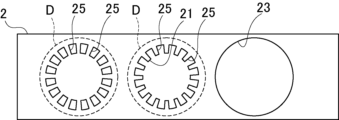
- the shape punching in the third stage 7 punches out the slot portion 25 of the core piece 27. Note that in Figure 2, the part that will become the outer circumference circle 23 of the core piece 27 is shown by the dashed line D. Also, the hole after the outer circumference punching of the core piece 27 is shown as the outer circumference circle 23.
- the inner circumference circle 21 and the outer circumference circle 23 are punched concentrically to form the iron core piece 27, and the slots 25 are arranged at equal intervals in the circumferential direction of the inner circumference circle 21 and the outer circumference circle 23.
- the slots 25 are arranged concentrically with respect to the inner circumference circle 21 and the outer circumference circle 23.
- the punching load of the third stage 7 is relatively large compared to the first and second stages 3 and 5. For this reason, the tip positions of the punches 9, 11, and 13 are set so that the punching timing of the third stage 7, which has the largest punching load, is delayed compared to all the other stages 3 and 5.
- the punching timing can be set so that the third stage 7, which has the largest punching load, is delayed relative to at least one of the other stages 3 or 5.
- the punching timing can be set so that the third stage 7 is slower than the first stage 3 and the second stage 5 is faster than the third stage 7, or the third stage 7 is slower than the second stage 5 and the first stage 3 is faster than the third stage 7.
- the punching load is the load required for punching by the press, and depends on the machining circumference of punches 9, 11, and 13.
- the machining circumference is the outer perimeter dimension of the cross section of each punch. The longer the machining circumference, the larger the punching load.
- the machining circumference of the punch 13 in the third stage 7 is the sum of the punches that punch each slot portion 25, and is longer than the first and second stages 3 and 5. Therefore, the punching load in the third stage 7 is the largest among the first to third stages 3, 5, and 7.
- the machining circumference of the punch 13 in the third stage 7 may be relatively shorter than the punches 9 and 11 in the first and second stages 3 and 5. For this reason, the punching load of the punch 13 is not necessarily the greatest in the third stage 7. The same applies when other stages are added.
- the heights of the tip positions of punches 9, 11, and 13 from the upper die 15 are in the following relationship: height H0 of tip position of punch 9 > height H1 of tip position of punch 11 > height H2 of tip position of punch 13.
- the protruding length of punch 13 in the third stage 7 from the upper die 15 is shorter than the protruding length of punches 9 and 11 in the first and second stages 3 and 5, and the protruding length of punch 11 in the second stage 5 is shorter than the protruding length of punch 9 in the first stage 3.
- the timing of punching the steel sheet 1 by the lowering of the upper die 15 is the order of punches 9, 11, and 13 on the first, second, and third stages 3, 5, and 7.
- the timing of punching by the punch 13 in the third stage 7 may be intermediate among the first to third stages 3, 5, and 7.
- [Punching method] In the punching method of this embodiment, first, the steel sheet 2 is fed and placed between the upper die 15 and the lower die 17. At this time, the steel sheet 2 is placed across the multiple stages 3, 5, and 7. In the first punching, the leading end of the steel sheet 2 in the feed direction is placed on the third stage 7, and in the second punching, the steel sheet 2 is placed across the first stage 3 and the third stage 7. Then, in the third punching and thereafter, the steel sheet 2 is placed across the first to third stages 3, 5, and 7.
- the timing of this punching is as follows: punches 9, 11, and 13 in the first, second, and third stages 3, 5, and 7. Note that in the second punching, the order is punches 9 and 13 in the first and third stages 3 and 7.
- punch 9 which has the smallest punching load, punches the steel plate 2 first, followed by punch 11, and punch 13, which has the largest punching load, punches last.
- punch 9 which has the smallest punching load, punches first, followed by punch 13, which has the largest punching load.
- the timing of punching by punch 13 in the third stage 7 may be intermediate among the first to third stages 3, 5, and 7, as described above.
- the third stage 7 which has the largest punching load, has a slower punching timing than the other first and second stages 3 and 5.
- the steel plate 2 can be positioned by the punches 9 and 11 of the first and second stages 3 and 5 that have previously performed punching, while punching can be performed by the punch 13 of the third stage 7, which has the largest punching load. This makes it possible to improve the processing accuracy of punching in the third stage 7 and suppress distortion of the steel plate 2 during punching in the third stage 7, thereby more reliably improving the processing accuracy of the core pieces 27.
- punching in the first and second stages 3 and 5, which are subsequent processes in the feed direction can be performed on steel plate 2 with reduced distortion, so the machining accuracy of core piece 27 can be improved more reliably.
- the punching timing of the punch 11 of the second stage 5 which has a relatively high punching load, is delayed relative to the punching timing of the punch 9 of the first stage 3, which has a relatively low punching load.
- the processing accuracy of the punching in the first stage 3, which is performed first can be improved. Also, while the steel plate 2 is positioned by the punch 9 in the first stage 3, which has performed the punching first, punching can be performed by the punch 11 in the second stage 5, which has a relatively large punching load. This makes it possible to more reliably improve the processing accuracy of the core pieces 27 and suppress distortion of the steel plate 2 during punching in the first stage 3. Therefore, it is possible to more reliably improve the processing accuracy of the core pieces 27. Also, even if the punching timing of the first and third stages 3 and 7 or the punching timing of the second and third stages 5 and 7 are simultaneous, the processing accuracy of the core pieces 27 can be improved.
- FIG. 3 is a schematic diagram of an upper die of a punching device according to a first modified example of the first embodiment.
- the height of the tip position is varied within the punch 13 of the third stage 7.
- punch 13 is configured as a punch that punches out slot portion 25, and has multiple punch portions 13a that correspond to slot portion 25. These punch portions 13a have different tip heights. Punch portions 13a are arranged along the circumferential direction, and accordingly, punching timing of punch 13 differs in the circumferential direction.
- FIG. 4 is a schematic diagram of an upper die of a punching device according to a second modified example of the first embodiment, as viewed from the feeding direction of the steel plate.
- the inner circumference circle 21, the outer circumference circle 23, and the slot portion 25 are punched out using punches 9, 11, and 13 in a single row of the first to third stages 3, 5, and 7, but in modification 2, punching is performed simultaneously in multiple rows.
- the first, second, and third stages 3, 5, and 7, each having the same processing order are provided in multiple rows, for example two rows, in the width direction of the steel plate 2.
- the mutual tip positions of the punches 9, 11, or 13 of the same stage 3, 5, or 7 may be set not only to be the same, but also to be different.
- the relationship between the tip positions of the punches 9, 11, and 13 of the different stages 3, 5, and 7 may be set by the average length of the punches 9, 11, or 13 of the same stage 3, 5, or 7, the length of the longest punch, or the length of the shortest punch.
- the punches 9 of the first stage 3 are arranged in two rows in the width direction of the steel plate 2, and the tip positions of the punches 9 of the same stage 3 differ depending on their length.
- the tip position of the punch 9 as the first stage 3 can be set using any of the following lengths: the average value of the tip positions of the punches 9 of the same stage 3 in two rows, the longest length, or the shortest length.
- the tip positions of the punches 9, 11, and 13 can be set arbitrarily as long as the relationship is maintained.
- the punching device 1 of Example 2 has rotor core stages 35, 37, and 39 arranged in succession upstream of stator core stages 3, 5, and 7 in the feed direction of the steel plate 2, as shown in Figures 5 and 6.
- the configuration has at least one other stage 3, 5, 35, 37, and 39 upstream and downstream of the third stage 7 of the stator core, where the punching load is maximum.
- rotor core stages 35, 37, and 39 are located upstream of the third stage 7 of the stator core
- stator core stages 3 and 5 are located downstream of the third stage 7 of the stator core.
- the punching device 1 of this embodiment has an upper die 15A equipped with punches 9, 11, and 13 configured in the same manner as in embodiment 1, and a lower die 17A equipped with a die 17a, for the stages 3, 5, and 7 of the stator core.
- stages 35, 37, and 39 of the rotor core there is an upper die 15B equipped with punches 41, 43, and 45, and a lower die 17B equipped with a die 17a.
- the upper die 15B is separated so as to operate separately from the upper die 15A.
- the lower die 17B is also separated from the lower die 17A and provided separately.
- the first stage 35 punches the inner circumference
- the second stage 37 punches the outer circumference
- the third stage 39 punches the shape.
- the inner circumference punching of the first stage 35 of the rotor core punches out the inner circumference circle 47 of the iron core piece 53.
- the outer circumference punching of the second stage 37 punches out the outer circumference circle 49 of the iron core piece 53.
- the shape punching of the third stage 39 punches out the magnet insertion hole 51 of the iron core piece 53.
- the inner circumference circle 47 and the outer circumference circle 49 are punched concentrically to form the iron core piece 53, and the magnet insertion holes 51 are arranged at equal intervals in the circumferential direction.
- the magnet insertion holes 51 are arranged concentrically with the inner circumference circle 47 and the outer circumference circle 49.
- FIG. 6 the portion that will become the outer circumferential circle 23 of the stator core piece 27 is shown by dashed line D1, and the portion that will become the outer circumferential circle 49 of the rotor core piece 53 is shown by dashed line D2.
- the holes that remain after punching out the outer circumferential circle of the core pieces 27 and 53 are shown as the outer circumferential circles 23 and 49.
- the punching timing of the punches 9, 11, and 13 of the first to third stages 3, 5, and 7 of the stator core and the punches 41, 43, and 45 of the first to third stages 35, 37, and 39 of the rotor core is different between at least two stages, and the punching tip positions are set in the punching direction.
- the punching load of the punch 13 of the third stage 7 of the stator core is the highest. For this reason, of all the punches for the iron core pieces 27 and 53 of the stator core and rotor core, the punch 13 is set to the lowest tip position height H2.
- the punches 9 and 11 of the first and second stages 3 and 5 of the stator core have the heights of the tip positions of the punches 9 and 11 set to H0 and H1, similar to Example 1.
- the punches 41, 43, and 45 of the first to third stages 35, 37, and 39 of the rotor core have tip heights set to H0, H1, and H0, respectively.
- the punch 43 in the second stage 37 which has the largest punching load, has its tip position set in the punching direction so that its punching timing differs from that of the other punches 41 and 45 in the first and third stages 35 and 39.
- the steel sheet 2 is first fed and placed between the upper die 15B and the lower die 17B.
- the leading end of the steel sheet 2 in the feed direction is placed in the third stage 39 of the rotor core
- the steel sheet 2 is placed across the first stage 35 to the third stage 39 of the rotor core.
- the steel sheet 2 is placed across the first to third stages 35, 37, and 39 of the rotor core.
- the steel sheet 2 sequentially straddles the first to third stages 3, 5, and 7 of the stator core during the fourth to sixth punchings. After that, the steel sheet 2 is placed across all the stages of the rotor core and the stator core.
- the timing of the punching process is such that punches 41 and 45 punch the rotor core first at the same time, followed by punch 43, depending on the tip position setting.
- punches 41 and 45 which have a relatively low punching load, perform punching first
- punch 43 which has a relatively high and maximum punching load, performs punching later.
- the stator core is punched in the same manner as in Example 1, with punches 9, 11, and 13 in that order.
- punch 9 of the stator core is punched simultaneously with punches 41 and 45 of the rotor core
- punch 11 of the stator core is punched simultaneously with punch 43 of the rotor core
- punch 13 of the stator core is punched.
- the punching timing of the rotor core iron piece 53 is delayed with respect to at least one of the stages 41 and 45 in the punch 43.
- the machining precision of the iron core pieces 53 of the rotor core can be improved more reliably.
- the second embodiment can achieve the same effects as the first embodiment.
- FIG. 7 is a schematic cross-sectional view of a punching device according to a modified example of the second embodiment.
- the punching device 1 As shown in FIG. 7, the punching device 1 according to the modified example is provided with punches 41, 43, 45, 9, 11, and 13 for the rotor core and the stator core in a common upper die 15. Accordingly, a die 17a is provided in a common lower die 17 corresponding to the second stages 37 and 5 of the rotor core and the stator core.
Landscapes
- Engineering & Computer Science (AREA)
- Mechanical Engineering (AREA)
- Manufacturing & Machinery (AREA)
- Power Engineering (AREA)
- Manufacture Of Motors, Generators (AREA)
Abstract
鉄心片の真円度を考慮した打ち抜きを可能にする打ち抜き装置を提供する。共通の鋼板2が跨って配置され、鋼板2に対する打ち抜きを順次行って鉄心片27を形成する複数のステージ3、5、及び7にそれぞれ対応してパンチ9、11、及び13を備え、複数のステージ3、5、及び7のパンチ9、11、及び13が共に下降して鋼板2に対する打ち抜きを行い、パンチ13は、パンチ9及び11に対して打ち抜きタイミングが後になるように打ち抜き方向の先端位置が設定された。
Description
本発明は、回転電機の積層鉄心に用いられる鉄心片を打ち抜く打ち抜き装置及び方法に関する。
従来の打ち抜き装置としては、例えば特許文献1のように複数のステージを備えたものがある。複数のステージは、鋼板が跨って配置され、パンチにより鋼板に対する打ち抜きを順次行って最終ステージで鉄心片を形成する。
この打ち抜き装置は、全ステージの打ち抜きが同時に行われると品質が低下することから、打ち抜き荷重が最も大きいパンチが最も早いタイミングで鋼板を押圧するように構成されている。
しかし、かかる従来の打ち抜き装置では、最初に鋼板を押圧する打ち抜き荷重が最も大きいパンチによって金型に局所的に高荷重が作用する。これにより、金型の変形等が生じてパンチが鋼板に対して傾いてしまい、その後に鋼板を押圧する他のステージのパンチによる打ち抜き精度が低下する。この結果、鉄心片の加工精度が低下するという問題があった。
解決しようとする問題点は、鉄心片の加工精度が低下する点である。
本発明は、共通の鋼板が跨って配置され前記鋼板に対する打ち抜きを順次行って鉄心片を形成する複数のステージにそれぞれ対応して設けられたパンチを備え、前記複数のステージの前記パンチが共に下降して前記鋼板に対する打ち抜きを行い、前記パンチは、打ち抜き荷重が最大であるステージでの打抜タイミングが少なくとも1つの他のステージの打抜タイミングに対して遅くなる打ち抜き方向の先端位置を有する、打ち抜き装置を提供する。
本発明は、共通の鋼板に対する打ち抜きを順次行って鉄心片を形成する複数のステージに前記鋼板を跨って配置し、前記複数のステージのパンチが共に下降して前記鋼板に対する打ち抜きを前記複数のステージにおいて行い、打ち抜き荷重が最大であるステージで少なくとも1つの他のステージに対して前記パンチの打ち抜きタイミングが遅い、打ち抜き方法を提供する。
本発明は、鉄心片の加工精度を向上することができる。
一実施形態の打ち抜き装置1は、共通の鋼板2が跨って配置され、鋼板2に対する打ち抜きを順次行って鉄心片27及び53を形成する複数のステージ3、5、7、35、37、及び39にそれぞれパンチ9、11、13、41、43、及び45を備える。複数のステージ3、5、7、35、37、及び39のパンチ9、11、13、41、43、及び45は、共に下降して鋼板2に対する打ち抜きを行う。このパンチ9、11、13、41、43、及び45は、打ち抜き荷重が最大であるステージ7での打抜タイミングが少なくとも1つの他のステージ3、5、35、37、39の打抜タイミングに対して遅くなる打ち抜き方向の先端位置を有する。
パンチ9、11、13、41、43、及び45は、打ち抜き荷重が最大であるステージ7で他の全てのステージ3、5、35、37、39に対して打ち抜きタイミングが遅いのが好ましい。
ステージは、第1ステージ3と、第2ステージ5と、第3ステージ7とを備えてもよい。第1ステージ3は、鉄心片27の内周円21を打ち抜く。第2ステージ5は、鉄心片27の外周円23を打ち抜く。第3ステージ7は、鉄心片27の形抜部25を打ち抜く。第3ステージ7は、第1及び第2ステージ3及び5に対し打ち抜き荷重が相対的に大きく、この場合、第3ステージ7は、第1及び第2ステージ3及び5のパンチ9及び11に対して打ち抜きタイミングが後になるように打ち抜き方向の先端位置が設定される。
打ち抜き装置1は、打ち抜き荷重が最大であるステージ7の上流と下流にそれぞれ少なくとも1つの他のステージ3、5、35、37、39を備えてもよい。
打ち抜き方法は、共通の鋼板2に対する打ち抜きを順次行って鉄心片27及び53を形成する複数のステージ3、5、7、35、37、及び39に鋼板2を跨って配置し、複数ステージ3、5、7、35、37、及び39のパンチ9、11、13、41、43、及び45が共に下降して複数ステージ3、5、7、35、37、及び39において鋼板2に対する打ち抜きを行う。打ち抜き荷重が最大であるステージ7では、少なくとも1つの他のステージ3、5、35、37、39に対してパンチ13の打ち抜きタイミングが遅い。
[打ち抜き装置]
図1は、本発明の実施例1に係る打ち抜き装置の概略図である。図2は、図1の打ち抜き装置で打ち抜いた鋼鈑の平面図である。
図1は、本発明の実施例1に係る打ち抜き装置の概略図である。図2は、図1の打ち抜き装置で打ち抜いた鋼鈑の平面図である。
図1の打ち抜き装置1は、回転電機の積層鉄心であるモーターコアに用いられる鉄心片27の打ち抜きを行う。本実施例のモーターコアは、ステーターコアであるが、ローターコアであってもよい。
この打ち抜き装置1は、上型15及び下型17を備える。これら上型15及び下型17が、鋼板2の送り方向に沿って配列された複数のステージとして第1、第2、及び第3ステージ3、5、及び7を備えている。ステージは、鉄心片27を複数回の工程で形成する場合の個々の工程である。
第1~第3ステージ3、5、及び7は、共通の鋼板2が跨って配置され、鋼板2に対する打ち抜きを送り方向で順次行って鉄心片27を形成する。これら第1~第3ステージ3、5、及び7は、それぞれパンチ9、11、及び13を備えている。
パンチ9、11、及び13は、上型15に取り付けられている。パンチ9、11、及び13は、上型15と共に下降する構成である。この下降により図示しないストリッパーが下型17に対して鋼板2を先行して押え、上型15が下型17に対してさらに下降する。これにより、第1~第3ステージ3、5、及び7のパンチ9、11、及び13がさらに下降して鋼板2に対する打ち抜きを行う。
下型17には、第2ステージ5に応じてダイ17aを有する。ダイ17aは、ダイ本体17bに続くスクイーズリング17cが備えられている。ダイ本体17bは、パンチ11と協働して鉄心片27を打抜き、スクイーズリング17cは、打ち抜かれた鉄心片27に側圧を付与して保持する。従って、第2ステージ5では、パンチ11及びダイ17aにより打ち抜かれた鉄心片27がダイ17a内に順次保持されて積層される。なお、下型17には、図示しないが第1及び第3ステージ3及び7に対応してダイが設けられている。
本実施例の打ち抜き装置1では、図1及び図2のように、第1ステージ3が鉄心片27の内周打ち抜き、第2ステージ5が鉄心片27の外周打ち抜き、第3ステージ7が鉄心片27の形状打ち抜きを行う。
ただし、ステージの設定は任意である。凹凸によるかしめ部の形成や接着剤塗布等を他のステージとして追加することもできる。
第1ステージ3の内周打ち抜きは、鉄心片27の内周円21を打ち抜く。第2ステージ5の外周打ち抜きは、鉄心片27の外周円23を打ち抜く。第3ステージ7の形状打ち抜きは、鉄心片27のスロット部25を打ち抜く。なお、図2では、鉄心片27の外周円23となる部分を破線Dで示している。また、鉄心片27の外周打ち抜き後の孔を外周円23として示している。
内周円21及び外周円23は、鉄心片27として同心に打ち抜かれ、スロット部25は、内周円21及び外周円23の周方向で等間隔に配列されている。スロット部25の配列は、内周円21及び外周円23に対して同心円上での配列となっている。
[先端位置]
第1~第3ステージ3、5、及び7のパンチ9、11、及び13は、打ち抜き荷重の相違によって打ち抜き方向の先端位置が設定されている。
第1~第3ステージ3、5、及び7のパンチ9、11、及び13は、打ち抜き荷重の相違によって打ち抜き方向の先端位置が設定されている。
本実施例においては、第3ステージ7が第1及び第2ステージ3及び5に対し打ち抜き荷重が相対的に大きい。このため、パンチ9、11、及び13は、打ち抜き荷重が最大である第3ステージ7で他の全てのステージ3及び5に対して打ち抜きタイミングが遅くなるように先端位置が設定されている。
打ち抜きタイミングの設定は、打ち抜き荷重が最大である第3ステージ7が少なくとも1つの他のステージ3又は5に対して遅くなるように行えばよい。例えば、打ち抜きタイミングは、第3ステージ7で第1ステージ3よりも遅くすると共に第2ステージ5で第3ステージ7より早くし、或いは第3ステージ7で第2ステージ5よりも遅くすると共に第1ステージ3で第3ステージ7より早くしてもよい。
打ち抜き荷重は、プレスによる打ち抜きに必要な荷重であり、パンチ9、11、及び13の加工周長に応じたものとなる。加工周長は、個々のパンチの横断面における外周寸法である。加工周長が長くなると、打ち抜き荷重が大きくなる。
本実施例において、第3ステージ7のパンチ13の加工周長は、各スロット部25を打ち抜くパンチの合計であり、第1及び第2ステージ3及び5よりも長い。このため、第3ステージ7では、第1~第3ステージ3、5、及び7中で打ち抜き荷重が最大となっている。
ただし、スロット部25の数によっては第3ステージ7のパンチ13の加工周長が、第1及び第2ステージ3及び5のパンチ9及び11に対して相対的に短くなることもある。このため、第3ステージ7は、パンチ13の打ち抜き荷重が必ずしも最大となる訳ではない。また、他のステージが追加された場合も同様である。
図1では、パンチ9を鋼鈑1の表面に当接させた状態で、パンチ9、11、及び13の先端位置の高さを示している。この鋼鈑1の表面は、鋼鈑1が下型17上に送り込まれ、ストリッパーで下型17上に押さえ込まれたときのものである。
この鋼鈑1の表面を基準とし、上型15からのパンチ9、11、及び13の先端位置の高さは、パンチ9の先端位置の高さH0>パンチ11の先端位置の高さH1>パンチ13の先端位置の高さH2の関係とした。換言すると、第3ステージ7のパンチ13の上型15からの突出長さは、第1及び第2ステージ3及び5のパンチ9及び11の突出長さよりも短く、第2ステージ5のパンチ11の突出長さは、第1ステージ3のパンチ9の突出長さより短い。
かかる先端位置の設定により、上型15の下降による鋼鈑1の打ち抜きタイミングは、第1、第2、及び第3ステージ3、5、及び7のパンチ9、11、及び13の順になる。
なお、第3ステージ7のパンチ13による打ち抜きタイミングを、第1~第3ステージ3、5、及び7中で中間であってもよい。
第1及び第3ステージ3及び7は、第2ステージ5よりも鋼鈑1の送り方向で上流に配置されている。なお、送り方向は、鋼板1の延設方向並びにステージ3、5、及び7の配列方向でもある。第1及び第3ステージ3及び7間では、第1ステージ3が第3ステージ7の上流側に配置されることもある。この場合、第3ステージ7の上流と下流とにそれぞれ少なくとも1つの他のステージ3及び5が位置することになる。
[打ち抜き方法]
本実施例の打ち抜き方法では、まず鋼板2が送られて上型15及び下型17間に配置される。このとき、鋼板2が複数のステージ3、5、及び7に跨って配置される。なお、最初の打ち抜きにおいては、鋼板2の送り方向の先端部が第3ステージ7に配置され、二回目の打ち抜きにおいては、鋼板2が第1ステージ3から第3ステージ7に跨って配置される。そして、三回目以降の打ち抜きにおいては、鋼板2が第1~第3ステージ3、5、及び7に跨って配置される。
本実施例の打ち抜き方法では、まず鋼板2が送られて上型15及び下型17間に配置される。このとき、鋼板2が複数のステージ3、5、及び7に跨って配置される。なお、最初の打ち抜きにおいては、鋼板2の送り方向の先端部が第3ステージ7に配置され、二回目の打ち抜きにおいては、鋼板2が第1ステージ3から第3ステージ7に跨って配置される。そして、三回目以降の打ち抜きにおいては、鋼板2が第1~第3ステージ3、5、及び7に跨って配置される。
打ち抜きにおいては、上型15が下降すると、第1、第2、及び第3ステージ3、5、及び7のパンチ9、11、及び13が共に下降する。この下降により上型15側の図示しないストリッパーが鋼板2を押さえ込む。続いてパンチ9、11、及び13がストリッパーから突出し、三回目以降の打ち抜きにおいては内周円21、外周円23、及びスロット部25を打ち抜く。
この打ち抜きのタイミングは、上記の先端位置の設定により、第1、第2、及び第3ステージ3、5、及び7のパンチ9、11、及び13の順になる。なお、二回目の打ち抜きにおいては、第1及び第3ステージ3及び7のパンチ9及び13の順になる。
つまり、三回目以降の打ち抜きにおいては、鋼板2に対し、打ち抜き荷重が最小となるパンチ9が最初に打ち抜きを行い、続いてパンチ11が打ち抜きを行い、打ち抜き荷重が最大となるパンチ13が最後に打ち抜きを行う。二回目の打ち抜きにおいては、打ち抜き荷重が最小となるパンチ9が最初に打ち抜きを行い、続いて打ち抜き荷重が最大となるパンチ13が打ち抜きを行う。なお、第3ステージ7のパンチ13による打ち抜きタイミングは、上記のように第1~第3ステージ3、5、及び7中で中間としてもよい。
従って、パンチ9、11、及び13は、打ち抜き荷重が最大である第3ステージ7が他の第1及び第2ステージ3及び5に対して打ち抜きタイミングが遅い。
このため、本実施例では、第3ステージ7での打ち抜きによって上型15及び下型17に一時的に変形が生じたとしても、それよりも前に第1及び第2ステージ3及び5の打ち抜きが完了している。従って、第1及び第2ステージ3及び5での打ち抜きの加工精度を向上することができ、鉄心片27の加工精度を向上できる。
また、本実施例では、先に打ち抜きを行った第1及び第2ステージ3及び5のパンチ9及び11で鋼板2の位置決めを行いながら、打ち抜き荷重が最大の第3ステージ7のパンチ13による打ち抜きを行わせることができる。このため、第3ステージ7での打ち抜きの加工精度を向上することができると共に第3ステージ7での打ち抜き時の鋼板2の歪みを抑制でき、より確実に鉄心片27の加工精度を向上できる。
さらに、送り方向での後工程となる第1及び第2ステージ3及び5での打ち抜きを歪みが抑制された鋼板2に対して行うことができるので、より確実に鉄心片27の加工精度を向上することができる。
第1及び第2ステージ3及び5のパンチ9及び11間では、打ち抜き荷重が相対的に高い第2ステージ5のパンチ11の打ち抜きタイミングを、打ち抜き荷重が相対的に低い第1ステージ3のパンチ9の打ち抜きタイミングに対して遅らせている。
従って、本実施例では、先に行われる第1ステージ3での打ち抜きの加工精度を向上することができる。また、先に打ち抜きを行った第1ステージ3のパンチ9で鋼板2の位置決めを行いながら、相対的に打ち抜き荷重が大きい第2ステージ5のパンチ11による打ち抜きを行わせることができる。このため、より確実に鉄心片27の加工精度を向上することができると共に第1ステージ3での打ち抜き時の鋼板2の歪みを抑制できる。従って、より確実に鉄心片27の加工精度を向上することができる。また、仮に第1及び第3ステージ3及び7の打ち抜きタイミング又は第2及び第3ステージ5及び7の打ち抜きタイミングが同時であっても、鉄心片27の加工精度を向上できる。
[変形例1]
図3は、実施例1の変形例1に係る打ち抜き装置の上型の概略図である。
図3は、実施例1の変形例1に係る打ち抜き装置の上型の概略図である。
変形例1では、第3ステージ7のパンチ13内において、先端位置の高さを異ならせている。
具体的には、パンチ13は、スロット部25を打ち抜くパンチとして構成されており、スロット部25に対応した複数のパンチ部13aを有する。これらパンチ部13aは、先端位置の高さが異なっている。パンチ部13aは、周方向に沿って配置されており、これに応じて、パンチ13は、周方向で打ち抜きタイミングが異なっている。
かかる打ち抜きタイミングの設定により、パンチ13での打ち抜き荷重を緩和させて、より確実に打ち抜き精度を向上させることができる。この結果、本変形例では、より確実にスロット部25の精度を向上することができると共にスロット部25の打ち抜き時における鋼板2の歪みを抑制できる。
[変形例2]
図4は、実施例1の変形例2に係る打ち抜き装置の上型を鋼鈑の送り方向から見た概略図である。
図4は、実施例1の変形例2に係る打ち抜き装置の上型を鋼鈑の送り方向から見た概略図である。
上記実施例1では、内周円21、外周円23、及びスロット部25の打ち抜きを1列の第1~第3ステージ3、5、及び7のパンチ9、11、及び13で行う例を示したが、変形例2では、複数列で同時に抜きを行う。
変形例2では、同一の加工順序とした第1、第2、及び第3ステージ3、5、及び7が鋼板2の幅方向に複数列、例えば2列備えられている。
第1、第2、及び第3ステージ3、5、及び7の複数列の間では、同一ステージ3、5、又は7のパンチ9、11、又は13相互の先端位置が同一だけでなく異なる設定になってもよい。同一ステージ3、5、又は7のパンチ9、11、又は13相互の先端位置が異なる場合、異なるステージ3、5、及び7のパンチ9、11、及び13の先端位置の関係は、同一ステージ3、5、又は7のパンチ9、11、又は13の長さの平均値、最長のパンチの長さ、又は最短のパンチの長さによって設定すればよい。
例えば、図4では、第1ステージ3のパンチ9が鋼板2の幅方向に2列併設され、同一ステージ3のパンチ9の先端位置が長さに応じて異なっている。この場合、第1ステージ3としてのパンチ9の先端位置の設定は、2列の同一ステージ3のパンチ9の先端位置の平均値、最長の長さ、又は最短の長さの何れかの長さを用いて先端位置の設定を行わせることができる。ただし、各列において、パンチ9、11、及び13の先端位置は、その関係性が保持されている限り任意に設定可能である。
[打ち抜き装置]
図5は、実施例2に係る打ち抜き装置の概略図である。図6は、図5の打ち抜き装置で打ち抜いた鋼板の平面図である。なお、実施例2は、基本的な構成が実施例1と共通し、対応する構成を同符号で示して重複した説明を省略する。
図5は、実施例2に係る打ち抜き装置の概略図である。図6は、図5の打ち抜き装置で打ち抜いた鋼板の平面図である。なお、実施例2は、基本的な構成が実施例1と共通し、対応する構成を同符号で示して重複した説明を省略する。
実施例2の打ち抜き装置1は、図5及び図6のように、鋼板2の送り方向において、ステーターコアのステージ3、5、及び7の上流にローターコアのステージ35、37、及び39を連続して備えた。
これにより、打ち抜き荷重が最大であるステーターコアの第3ステージ7の上流と下流にそれぞれ少なくとも1つの他のステージ3、5、35、37、及び39を備えた構成となっている。具体的には、ステーターコアの第3ステージ7の上流にローターコアのステージ35、37、及び39が位置し、ステーターコアの第3ステージ7の下流にステーターコアのステージ3及び5が位置する。
かかる本実施例の打ち抜き装置1は、ステーターコアのステージ3、5、及び7に対し、実施例1と同様に構成されたパンチ9、11、13を備えた上型15Aとダイ17aを備えた下型17Aとを有する。
ローターコアのステージ35、37、及び39に対しては、パンチ41、43、及び45を備えた上型15Bとダイ17aを備えた下型17Bとを有する。上型15Bは、上型15Aとは別に動作するように切り離されている。下型17Bも、下型17Aとは切り離されて別に設けられている。
本実施例2のローターコアの鉄心片53の打ち抜きでは、第1ステージ35が内周打ち抜き、第2ステージ37が外周打ち抜き、第3ステージ39が形状打ち抜きを行う。
ローターコアの第1ステージ35の内周打ち抜きは、鉄心片53の内周円47を打ち抜く。第2ステージ37の外周打ち抜きは、鉄心片53の外周円49を打ち抜く。第3ステージ39の形状打ち抜きは、鉄心片53の磁石挿入孔51を打ち抜く。
内周円47及び外周円49は、鉄心片53として同心に打ち抜かれ、磁石挿入孔51は、周方向で等間隔に配列されている。磁石挿入孔51の配列は、内周円47及び外周円49に対し同心円上の配列となっている。
なお、図6では、ステーターコアの鉄心片27の外周円23となる部分を破線D1及びローターコアの鉄心片53の外周円49となる部分を破線D2で示している。また、鉄心片27及び53の外周打ち抜き後の孔を外周円23及び49として示している。
[先端位置]
図5のように、実施例2では、ステーターコアの第1~第3ステージ3、5、及び7のパンチ9、11、及び13とローターコアの第1~第3ステージ35、37及び39のパンチ41、43、及び45とにおいて、少なくとも2つのステージ間で打ち抜きタイミングが異なるように打ち抜き方向の先端位置を設定している。
図5のように、実施例2では、ステーターコアの第1~第3ステージ3、5、及び7のパンチ9、11、及び13とローターコアの第1~第3ステージ35、37及び39のパンチ41、43、及び45とにおいて、少なくとも2つのステージ間で打ち抜きタイミングが異なるように打ち抜き方向の先端位置を設定している。
具体的には、ステーターコアの第3ステージ7のパンチ13の打ち抜き荷重が最も高くなる。このため、ステーターコア及びローターコアの鉄心片27及び53に対する全てのパンチの内、パンチ13を最も低い先端位置の高さH2に設定している。
ステーターコアの第1及び第2ステージ3及び5のパンチ9及び11は、実施例1と同様に、パンチ9及び11の先端位置の高さをH0及びH1に設定されている。
ローターコアの第1~第3ステージ35、37、及び39のパンチ41、43、及び45は、それぞれ先端位置の高さがH0、H1、及びH0に設定されている。
パンチ41、43、及び45の中では、打ち抜き荷重が最大である第2ステージ37のパンチ43で他の第1及び第3ステージ35及び39のパンチ41及び45に対し打ち抜きタイミングが異なるように打ち抜き方向の先端位置が設定されている。
[打ち抜き方法]
本実施例の打ち抜き方法では、まず鋼板2が送られて上型15B及び下型17B間に配置される。最初の打ち抜きにおいては、鋼板2の送り方向の先端部がローターコアの第3ステージ39に配置され、二回目の打ち抜きにおいては、鋼板2がローターコアの第1ステージ35から第3ステージ39に跨って配置される。そして、三回目以降の打ち抜きにおいては、鋼板2がローターコアの第1~第3ステージ35、37、及び39に跨って配置される。ステーターコアの第1~第3ステージ3、5、及び7には、四回目~六回目の打ち抜き時に鋼板2が順次跨る。その後は、ローターコア及びステーターコアの全てのステージに鋼板2が跨って配置される。
本実施例の打ち抜き方法では、まず鋼板2が送られて上型15B及び下型17B間に配置される。最初の打ち抜きにおいては、鋼板2の送り方向の先端部がローターコアの第3ステージ39に配置され、二回目の打ち抜きにおいては、鋼板2がローターコアの第1ステージ35から第3ステージ39に跨って配置される。そして、三回目以降の打ち抜きにおいては、鋼板2がローターコアの第1~第3ステージ35、37、及び39に跨って配置される。ステーターコアの第1~第3ステージ3、5、及び7には、四回目~六回目の打ち抜き時に鋼板2が順次跨る。その後は、ローターコア及びステーターコアの全てのステージに鋼板2が跨って配置される。
打ち抜きにおいては、上型15B、15Aが下降すると、ローターコア及びステーターコアの第1~第3ステージ35、37、及び39並びに3、5、及び7のパンチ41、43、及び45並びに9、11、及び13が共に下降する。この下降により上型15B及び15Aの図示しないストリッパーが鋼板2を押さえ込む。続いてパンチ41、43、及び45並びに9、11、及び13が図示しないストリッパーから突出して内周円47及び21、外周円49及び23、並びに磁石挿入孔51及びスロット部25を打ち抜く。
打ち抜き加工のタイミングは、先端位置の設定により、ローターコアの打ち抜きにおいて、パンチ41及び45の打ち抜きが同タイミングで先行し、遅れてパンチ43の打ち抜きの順になる。
つまり、打ち抜き荷重が相対的に低いパンチ41及び45が最初に打ち抜きを行い、打ち抜き荷重が相対的に高く最大となるパンチ43が遅れて打ち抜きを行う。
また、ステーターコアの打ち抜きは、実施例1と同様に行われ、パンチ9、11、及び13の順で行われる。ローターコア及びステーターコアの全体の打ち抜きにおいては、ステーターコアのパンチ9がローターコアのパンチ41及び45と同時に打ち抜きが行われ、ステーターコアのパンチ11がローターコアのパンチ43と同時に打ち抜きが行われ、最後にステーターコアのパンチ13による打ち抜きが行われる。
従って、ローターコア及びステーターコアの鉄心片27及び53に対する打ち抜きを一括して行う場合でも、鉄心片27及び53の加工精度を向上することができる。
また、ローターコアの鉄心片53の打ち抜き自体も、パンチ43において、少なくとも1つのステージ41及び45に対して打ち抜きタイミングが遅い。
このため、より確実にローターコアの鉄心片53の加工精度を向上できる。その他、実施例2においても、実施例1と同様の作用効果を奏することができる。
[変形例]
図7は、実施例2の変形例に係る打ち抜き装置の一部を断面にして示す概略図である。
図7は、実施例2の変形例に係る打ち抜き装置の一部を断面にして示す概略図である。
図7のように、変形例に係る打ち抜き装置1は、共通の上型15にローターコア及びステーターコアのパンチ41、43、45、9、11、及び13が備えられている。これに応じて、共通の下型17にローターコア及びステーターコアの第2ステージ37及び5に対応してダイ17aが備えられている。
かかる変形例においても、実施例2と同様の作用効果を奏することができる。
1 鋼板
3 第1ステージ(ステーターコア用)
5 第2ステージ(ステーターコア用)
7 第3ステージ(ステーターコア用)
9、11、13 パンチ(ステーターコア用)
27 鉄心片(ステーターコア用)
35 第1ステージ(ローターコア用)
37 第2ステージ(ローターコア用)
39 第3ステージ(ローターコア用)
41、43、45 パンチ(ローターコア用)
53 鉄心片(ローターコア用)
3 第1ステージ(ステーターコア用)
5 第2ステージ(ステーターコア用)
7 第3ステージ(ステーターコア用)
9、11、13 パンチ(ステーターコア用)
27 鉄心片(ステーターコア用)
35 第1ステージ(ローターコア用)
37 第2ステージ(ローターコア用)
39 第3ステージ(ローターコア用)
41、43、45 パンチ(ローターコア用)
53 鉄心片(ローターコア用)
Claims (8)
- 共通の鋼板が跨って配置され前記鋼板に対する打ち抜きを順次行って鉄心片を形成する複数のステージにそれぞれ対応して設けられたパンチを備え、
前記複数のステージの前記パンチが共に下降して前記鋼板に対する打ち抜きを行い、
前記パンチは、打ち抜き荷重が最大であるステージでの打抜タイミングが少なくとも1つの他のステージの打抜タイミングに対して遅くなる打ち抜き方向の先端位置を有する、
打ち抜き装置。 - 請求項1の打ち抜き装置であって、
前記パンチは、前記先端位置により、前記打ち抜き荷重が最大であるステージで他の全てのステージに対して打ち抜きタイミングが遅い、
打ち抜き装置。 - 請求項1の打ち抜き装置であって、
前記ステージは、前記鉄心片の内周円を打ち抜く第1ステージと、前記鉄心片の外周円を打ち抜く第2ステージと、前記鉄心片の形抜部を打ち抜く第3ステージとを備え、
前記第3ステージは、前記第1及び第2ステージに対して打ち抜き荷重が相対的に大きく、
前記第3ステージのパンチは、前記先端位置により、前記第1及び第2ステージのパンチに対して打ち抜きタイミングが後になる、
打ち抜き装置。 - 請求項1の打ち抜き装置であって、
前記打ち抜き荷重が最大であるステージの上流と下流にそれぞれ少なくとも1つの前記他のステージを備えた
打ち抜き装置。 - 共通の鋼板に対する打ち抜きを順次行って鉄心片を形成する複数のステージに前記鋼板を跨って配置し、
前記複数のステージのパンチが共に下降して前記鋼板に対する打ち抜きを前記複数のステージにおいて行い、
打ち抜き荷重が最大であるステージで少なくとも1つの他のステージに対して前記パンチの打ち抜きタイミングが遅い、
打ち抜き方法。 - 請求項5の打ち抜き方法であって、
前記打ち抜き荷重が最大であるステージで他の全てのステージに対して前記パンチの打ち抜きタイミングが遅い、
打ち抜き方法。 - 請求項5の打ち抜き方法であって、
前記ステージは、前記鉄心片の内周円を打ち抜く第1ステージと、前記鉄心片の外周円を打ち抜く第2ステージと、前記鉄心片の形抜部を打ち抜く第3ステージとを備え、
前記第3ステージは、前記第1及び第2ステージに対し打ち抜き荷重が相対的に大きく、
前記第3ステージのパンチは、前記第1及び第2ステージのパンチに対して打ち抜きタイミングが異なる、
打ち抜き方法。 - 請求項5の打ち抜き方法であって、
前記打ち抜き荷重が最大であるステージの上流と下流にそれぞれ少なくとも1つの前記他のステージを位置させる、
打ち抜き方法。
Applications Claiming Priority (2)
| Application Number | Priority Date | Filing Date | Title |
|---|---|---|---|
| JP2023-223695 | 2023-12-28 | ||
| JP2023223695 | 2023-12-28 |
Publications (1)
| Publication Number | Publication Date |
|---|---|
| WO2025142995A1 true WO2025142995A1 (ja) | 2025-07-03 |
Family
ID=96219149
Family Applications (1)
| Application Number | Title | Priority Date | Filing Date |
|---|---|---|---|
| PCT/JP2024/045851 Pending WO2025142995A1 (ja) | 2023-12-28 | 2024-12-25 | 打ち抜き装置及び方法 |
Country Status (1)
| Country | Link |
|---|---|
| WO (1) | WO2025142995A1 (ja) |
Citations (6)
| Publication number | Priority date | Publication date | Assignee | Title |
|---|---|---|---|---|
| JP2002325402A (ja) * | 2001-04-27 | 2002-11-08 | Kuroda Precision Ind Ltd | 積層鉄心の製造方法及び装置 |
| JP2005081413A (ja) * | 2003-09-10 | 2005-03-31 | Aisin Aw Co Ltd | プレス加工装置における打ち抜き用雄型 |
| WO2009096257A1 (ja) * | 2008-02-01 | 2009-08-06 | Sumiden Electronics, Ltd. | プレス装置 |
| CN205651705U (zh) * | 2016-05-06 | 2016-10-19 | 深圳市铭利达精密机械有限公司 | 一种冲头组件及油压机 |
| JP2018069251A (ja) * | 2016-10-24 | 2018-05-10 | Shマテリアル株式会社 | 打ち抜き加工用金型、打抜き加工方法、およびリードフレームの製造方法 |
| CN213530405U (zh) * | 2020-10-28 | 2021-06-25 | 深圳市诚瑞丰科技股份有限公司 | 一种密集孔板件的易脱料精密冲压模具 |
-
2024
- 2024-12-25 WO PCT/JP2024/045851 patent/WO2025142995A1/ja active Pending
Patent Citations (6)
| Publication number | Priority date | Publication date | Assignee | Title |
|---|---|---|---|---|
| JP2002325402A (ja) * | 2001-04-27 | 2002-11-08 | Kuroda Precision Ind Ltd | 積層鉄心の製造方法及び装置 |
| JP2005081413A (ja) * | 2003-09-10 | 2005-03-31 | Aisin Aw Co Ltd | プレス加工装置における打ち抜き用雄型 |
| WO2009096257A1 (ja) * | 2008-02-01 | 2009-08-06 | Sumiden Electronics, Ltd. | プレス装置 |
| CN205651705U (zh) * | 2016-05-06 | 2016-10-19 | 深圳市铭利达精密机械有限公司 | 一种冲头组件及油压机 |
| JP2018069251A (ja) * | 2016-10-24 | 2018-05-10 | Shマテリアル株式会社 | 打ち抜き加工用金型、打抜き加工方法、およびリードフレームの製造方法 |
| CN213530405U (zh) * | 2020-10-28 | 2021-06-25 | 深圳市诚瑞丰科技股份有限公司 | 一种密集孔板件的易脱料精密冲压模具 |
Similar Documents
| Publication | Publication Date | Title |
|---|---|---|
| JP5352445B2 (ja) | 積層鉄心の製造方法 | |
| JP6315537B2 (ja) | 積層鉄心の製造方法及びその製造装置 | |
| JP5875746B2 (ja) | 固定子鉄心の製造方法 | |
| US10298103B2 (en) | Manufacturing method of laminated core and manufacturing device of laminated core | |
| JP2010213505A (ja) | 分割鉄心片の製造方法及びこれを用いた固定子鉄心 | |
| JP3149217B2 (ja) | 積層鉄心用薄板の多列打抜き方法 | |
| KR101867186B1 (ko) | 쇼바씰 제조용 프레스 공정의 소재두께 보정방법 및 그 금형 | |
| JP4898240B2 (ja) | 鉄心片の製造方法 | |
| JP2015188934A (ja) | 薄鋼板の打抜き加工方法及び打抜き加工金型 | |
| WO2025142995A1 (ja) | 打ち抜き装置及び方法 | |
| US20160243605A1 (en) | Die apparatus and manufacturing method of metal product using die apparatus | |
| JP7136821B2 (ja) | 順送プレス加工方法 | |
| JP4749748B2 (ja) | 鉄心の打ち抜き製造方法 | |
| JP7733528B2 (ja) | 順送り金型装置および積層鉄心の製造方法 | |
| JP2010093997A (ja) | 積層鉄心の製造方法及び金型装置 | |
| JP4115765B2 (ja) | 押圧支持リングを設けた金型装置 | |
| JP4989877B2 (ja) | 回転子積層鉄心の製造方法 | |
| JPS606299A (ja) | 順送り打ち抜き方法 | |
| JP2011061958A (ja) | 積層鉄心の製造方法及びこれを用いて製造した積層鉄心 | |
| JP5462675B2 (ja) | 積層鉄心の製造方法 | |
| KR100964023B1 (ko) | 적층 코아 제조 장치의 에어 갭 다이 및 이를 채용한 적층코아 제조 장치 | |
| JP2001190048A (ja) | 鉄心打抜き方法 | |
| KR100522534B1 (ko) | 적층 코아 제조장치 및 그 제조방법 | |
| WO2019202930A1 (ja) | プレス加工製品製造装置 | |
| WO2018066518A1 (ja) | 鉄心片の製造方法 |
Legal Events
| Date | Code | Title | Description |
|---|---|---|---|
| 121 | Ep: the epo has been informed by wipo that ep was designated in this application |
Ref document number: 24912881 Country of ref document: EP Kind code of ref document: A1 |
|
| ENP | Entry into the national phase |
Ref document number: 2025567176 Country of ref document: JP Kind code of ref document: A |
|
| WWE | Wipo information: entry into national phase |
Ref document number: 2025567176 Country of ref document: JP |