WO2025143003A1 - Système d'imagerie, dispositif d'imagerie et procédé de commande d'imagerie - Google Patents
Système d'imagerie, dispositif d'imagerie et procédé de commande d'imagerie Download PDFInfo
- Publication number
- WO2025143003A1 WO2025143003A1 PCT/JP2024/045865 JP2024045865W WO2025143003A1 WO 2025143003 A1 WO2025143003 A1 WO 2025143003A1 JP 2024045865 W JP2024045865 W JP 2024045865W WO 2025143003 A1 WO2025143003 A1 WO 2025143003A1
- Authority
- WO
- WIPO (PCT)
- Prior art keywords
- screen
- user
- photographing
- display
- shooting
- Prior art date
- Legal status (The legal status is an assumption and is not a legal conclusion. Google has not performed a legal analysis and makes no representation as to the accuracy of the status listed.)
- Pending
Links
Images








Classifications
-
- G—PHYSICS
- G01—MEASURING; TESTING
- G01B—MEASURING LENGTH, THICKNESS OR SIMILAR LINEAR DIMENSIONS; MEASURING ANGLES; MEASURING AREAS; MEASURING IRREGULARITIES OF SURFACES OR CONTOURS
- G01B11/00—Measuring arrangements characterised by the use of optical techniques
- G01B11/24—Measuring arrangements characterised by the use of optical techniques for measuring contours or curvatures
-
- G—PHYSICS
- G01—MEASURING; TESTING
- G01C—MEASURING DISTANCES, LEVELS OR BEARINGS; SURVEYING; NAVIGATION; GYROSCOPIC INSTRUMENTS; PHOTOGRAMMETRY OR VIDEOGRAMMETRY
- G01C15/00—Surveying instruments or accessories not provided for in groups G01C1/00 - G01C13/00
-
- G—PHYSICS
- G03—PHOTOGRAPHY; CINEMATOGRAPHY; ANALOGOUS TECHNIQUES USING WAVES OTHER THAN OPTICAL WAVES; ELECTROGRAPHY; HOLOGRAPHY
- G03B—APPARATUS OR ARRANGEMENTS FOR TAKING PHOTOGRAPHS OR FOR PROJECTING OR VIEWING THEM; APPARATUS OR ARRANGEMENTS EMPLOYING ANALOGOUS TECHNIQUES USING WAVES OTHER THAN OPTICAL WAVES; ACCESSORIES THEREFOR
- G03B17/00—Details of cameras or camera bodies; Accessories therefor
- G03B17/56—Accessories
-
- H—ELECTRICITY
- H04—ELECTRIC COMMUNICATION TECHNIQUE
- H04N—PICTORIAL COMMUNICATION, e.g. TELEVISION
- H04N23/00—Cameras or camera modules comprising electronic image sensors; Control thereof
- H04N23/50—Constructional details
- H04N23/55—Optical parts specially adapted for electronic image sensors; Mounting thereof
-
- H—ELECTRICITY
- H04—ELECTRIC COMMUNICATION TECHNIQUE
- H04N—PICTORIAL COMMUNICATION, e.g. TELEVISION
- H04N23/00—Cameras or camera modules comprising electronic image sensors; Control thereof
- H04N23/60—Control of cameras or camera modules
- H04N23/63—Control of cameras or camera modules by using electronic viewfinders
-
- H—ELECTRICITY
- H04—ELECTRIC COMMUNICATION TECHNIQUE
- H04N—PICTORIAL COMMUNICATION, e.g. TELEVISION
- H04N5/00—Details of television systems
- H04N5/222—Studio circuitry; Studio devices; Studio equipment
Definitions
- This disclosure relates to an imaging device that captures images of a measurement target location in order to perform three-dimensional measurement processing that generates three-dimensional spatial information about the measurement target location.
- a 3D measurement technique is known that generates a point cloud representing the object to be measured in 3D space based on images of the object.
- the SLAM Simultaneous Localization And Mapping
- a moving object e.g. a worker holds a camera and uses images of the object to be measured from various directions to perform self-location estimation to obtain the object's own position information, and mapping to generate a point cloud representing the object to be measured in 3D space.
- a known technology related to this type of SLAM method is to present to the user areas where photography is insufficient using an image of an arrow indicating the direction and speed of movement of the imaging device (sensor) held by the user, or an image that distinguishes the direction of measured areas from the direction of unmeasured areas (see Patent Document 1).
- a tablet PC (the measurement device itself) equipped with a distance sensor and a visible camera is used as the imaging device for photographing the location to be measured, and the user holds the imaging device in both hands and walks through the location to be measured to photograph the location to be measured.
- the primary objective of this disclosure is to provide a photographing device that allows the user to continue photographing easily without imposing a heavy burden on the user, even when the photographing range is wide or photographing from high places is required.
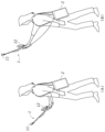
- FIG. 1 is an explanatory diagram showing a situation of a photographing operation performed by a user using the photographing system according to the first embodiment; An explanatory diagram showing a standard shooting state and a high-altitude shooting state.
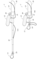
- FIG. 1 is a perspective view showing a support for the imaging device; A side view showing the expansion and contraction state of the support of the imaging device.
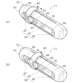
- FIG. 1 is a perspective view showing a sensor unit of an imaging device.
- FIG. 1 is a block diagram showing a schematic configuration of a photographing device and a control device. A block diagram showing an overview of the processing performed by the processor of the control device.
- FIG. 13 is an explanatory diagram showing a list of photographed data displayed on a display of a control device.
- FIG. 13 is an explanatory diagram showing a shooting standby screen displayed on a touch panel display of the shooting device.
- FIG. 13 is an explanatory diagram showing a screen displayed during shooting on a touch panel display of the shooting device.
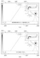
- FIG. 11 is an explanatory diagram showing the transition state of the available shooting time guide section on the shooting screen;
- FIG. 13 is an explanatory diagram showing the shooting screen with a message window displayed An explanatory diagram showing the contents and timing of messages displayed in the message window
- FIG. 13 is an explanatory diagram showing a confirmation screen for confirming the end of imaging, which is displayed on a touch panel display of the imaging device;
- FIG. 13 is an explanatory diagram showing a self-position lost notification screen displayed on a touch panel display of the imaging device;
- the first invention made to solve the above problem is an imaging device that images a location to be measured in order to perform a three-dimensional measurement process that generates three-dimensional spatial information of the location to be measured, and includes a sensor unit including a camera that images the location to be measured, a display input panel unit including a touch panel display that displays a screen to assist the user in the imaging operation and detects screen operations by the user, and a rod-shaped support body that supports the sensor unit and the display input panel unit, the support body having a grip portion that the user holds with one hand, the sensor portion being fixed to the end of the support body opposite the grip portion, and the display input panel portion being fixed to a position on the support body between the grip portion and the sensor portion.
- a sensor unit including a camera that images the location to be measured
- a display input panel unit including a touch panel display that displays a screen to assist the user in the imaging operation and detects screen operations by the user
- a rod-shaped support body that supports the sensor unit and the display input panel unit, the support body having
- the support has an extendable rod portion that changes the position of the sensor portion relative to the grip portion.
- the overall length of the imaging device is shortened, making it easier to carry and store the imaging device when not in use.
- the third invention further includes a cable that connects the sensor unit and the display input panel unit.
- the sensor unit and the display input panel unit are connected via a cable, so the sensor unit and the display input panel unit can be placed apart.
- the display input panel unit includes a first connection terminal to which a first cable that connects the sensor unit and the display input panel unit is detachably coupled, and a second connection terminal to which a second cable that connects a control device that controls the device itself and the display input panel unit is detachably coupled.
- the display input panel unit may include a repeater that relays data communication between the control device and the sensor unit, and the second cable may be used for data communication between the control device and the display input unit and for data communication between the control device and the sensor unit.
- the sixth invention further includes a wireless communication unit that wirelessly communicates with an information processing device that generates display information for displaying a screen that assists the user in taking photographs on the touch panel display, and the wireless communication unit is configured to transmit photographing information including an image taken by the camera and to receive the display information from the information processing device.
- the information processing device is placed in an appropriate location for use. This eliminates the inconvenience of the user having to constantly carry the information processing device, for example by hanging it on their shoulder, while taking pictures, as occurs when the photographing device is connected to the information processing device via a wire.
- the seventh invention is configured such that the camera takes color photographs, and the sensor unit has a neutral density filter that is movable between a position that covers the lens of the camera and a position that does not cover the lens of the camera.
- the eighth invention made to solve the above problem is an imaging system that includes an imaging device that images the location to be measured and a processor that controls the imaging device in order to perform 3D measurement processing to generate 3D spatial information of the location to be measured
- the imaging device includes a sensor unit including a camera that images the location to be measured, a display input panel unit including a touch panel display that displays a screen to assist the user in the imaging work and detects screen operations by the user, and a support body that supports the sensor unit and the display input panel unit, the support body having a grip part that the user holds in one hand, the display input panel unit being disposed in the vicinity of the grip part, and the processor being configured to display on the touch panel display at least an operation screen on which the user gives an instruction to start imaging.
- the imaging device By holding the grip part with one hand, the imaging device can be held stably with one hand, and the other hand can be used to easily operate the touch panel display to give instructions and make settings related to imaging.
- the processor that controls the imaging device may be provided in a control device separate from the imaging device, or may be provided in the imaging device itself.
- the ninth invention is configured such that the processor causes the touch panel display to display, as the operation screen, a shooting standby screen, a shooting in progress screen, and a shooting end confirmation screen in a sequential manner in response to a user's instruction.
- the tenth invention is configured such that the processor displays the shooting standby screen including an operation unit that allows the user to select one of a plurality of shooting modes having different control conditions for the camera.
- the processor is configured to notify the user of the saving of the captured image data and the return to the capture standby screen when capture ends, and to display the capture end confirmation screen including an operation unit for the user to input confirmation.
- the sixteenth invention is configured such that the processor detects a connection failure on the communication path between the camera and the touch panel display and the processor, and causes the touch panel display to display a screen notifying the user of the occurrence of the connection failure.
- this allows the user to hold the imaging device stably in one hand by grasping the grip portion with the other hand, and therefore allows the user to easily operate the touch panel display to give instructions and make settings regarding imaging with the other hand.
- the control device 2 is configured as a laptop or tablet PC that can be carried by the user (worker). In the example shown in FIG. 1, the control device 2 is stored in a shoulder bag and can be carried by the user, but the manner in which the user carries the control device 2 is not limited to this.
- the user holds the imaging device 1 in his/her hand and walks through the location to be measured, causing the imaging device 1 to capture images of the location to be measured. At this time, the user can change the position (height) of the sensor unit 11 by moving the arm holding the imaging device 1.
- the user can take a picture by positioning the sensor unit 11 at approximately the same height as the user's eye level by extending the arm holding the imaging device 1 slightly forward (standard imaging state).
- the user can take a picture by positioning the sensor unit 11 at a higher position than the user's eye level by raising the arm holding the imaging device 1 (high altitude imaging state).
- Figure 3 is a perspective view showing the support 13.
- Figure 4 is a side view showing the expansion and contraction state of the support 13.
- the support 13 of the imaging device 1 includes a main body 31, an extendable rod 32, a sensor mounting section 33, a panel mounting section 34, and a grip section 35.
- the display input panel section 12 includes a touch panel display 36.
- the panel mounting section 34 is provided on the main body section 31.
- the panel mounting section 34 includes a joint 41 (ball joint) that connects the display input panel section 12 and the main body section 31.
- the joint 41 can change the orientation of the display input panel section 12, that is, the orientation of the display surface of the touch panel display 36.
- the display input panel section 12 can perform a tilt operation that changes the orientation of the display input panel section 12 up and down and a pan operation that changes the orientation of the display input panel section 12 left and right by rotating the display input panel section 12 around two axes A1 and A2 that pass through the center of the joint 41 (ball joint).
- the panel mounting section 34 is also provided with a fixing knob 42. The user can fix the orientation of the display input panel section 12 by operating the fixing knob 42.
- the joint 41 is a ball joint, the orientation of the display input panel section 12 can be adjusted to any direction within a predetermined angle range.
- the user can adjust the orientation of the display input panel unit 12 as appropriate, improving the visibility and operability of the touch panel display 36.
- adjusting the orientation of the display input panel unit 12 in the tilt direction makes it easier to view and operate the screen of the touch panel display 36.
- adjusting the orientation of the display input panel unit 12 in the pan direction so that the screen of the touch panel display 36 faces to the left, where the user's face and left hand that operates the screen are located, makes it easier to view and operate the screen of the touch panel display 36.
- the sensor mounting section 33 is provided at the tip of the telescopic rod section 32.
- the sensor mounting section 33 has a joint 43 (hinge joint) that connects the sensor section 11 to the tip of the telescopic rod section 32.
- This joint 43 allows the orientation of the sensor section 11 to be changed.
- the sensor section 11 can be caused to perform a tilting operation that changes the orientation of the sensor section 11 up and down by rotating the sensor section 11 around the central axis A3 of the joint 43 (hinge joint).
- the sensor mounting section 33 is provided with a fixing knob 44. The user can fix the orientation of the sensor section 11 by operating the fixing knob 44.
- the display input panel unit 12 can be tilted and panned by the joint 41 made of a ball joint in the panel mounting portion 34, but the display input panel unit 12 may be tilted and panned by a combination of multiple hinge joints.
- the joint 43 in the sensor mounting section 33 is a hinge joint, which allows only a tilting motion to change the orientation of the sensor section 11 up and down, but it may also allow a panning motion to change the orientation of the sensor section 11 left and right.
- the joint 43 may be a ball joint or a combination of multiple hinge joints.
- the telescopic rod section 32 is configured to be telescopic in the axial direction.
- the telescopic rod section 32 has a structure in which multiple sheath tubes with gradually decreasing diameters are slidably connected.
- the user can change the position of the sensor portion 11 relative to the grip portion 35 held by the hand. That is, as shown in FIG. 4(A), when the telescopic rod portion 32 is extended (extended state), the sensor portion 11 is separated from the grip portion 35. This allows the sensor portion 11 to be positioned at a high position when photographing at high altitudes (see FIG. 2(B)).
- FIG. 4(B) when the telescopic rod portion 32 is retracted and most of the telescopic rod portion 32 is stored in the main body portion 31 (stored state), the overall length of the imaging device 1 is shortened, making it easier to carry and store the imaging device 1 when not in use.
- the user can hold the imaging device 1 stably in one hand by grasping the grip portion 35 with the hand. Therefore, the user can take pictures by orienting the sensor unit 11 in any direction by changing the orientation of the arm or body holding the imaging device 1 while taking pictures. In addition, the user can adjust the position of the sensor unit 11 by extending and retracting the extendable rod even while taking pictures, and can also adjust the orientation of the display input panel unit 12.
- the display input panel unit 12 is fixed to the main body unit 31, but the display input panel unit 12 may be fixed to the middle of the extendable rod unit 32 so that the position of the display input panel unit 12 relative to the grip unit 35 can be adjusted.
- the display input panel unit 12 may be fixed to the main body unit 31 via a movable member (not shown) separate from the extendable rod unit 32 to which the sensor unit 11 is fixed at its tip.
- Figure 5 is a perspective view showing the sensor unit 11.
- the sensor section 11 includes a sensor unit 51 and a sensor cover 52.
- the sensor unit 51 includes a visible camera 53 and a depth sensor 54.
- the visible camera 53 (color camera) captures color images of the subject.
- the depth sensor 54 includes an infrared projector 55 and left and right infrared cameras 56, 57 (stereo cameras).
- the infrared projector 55 irradiates the subject with infrared light.
- the left and right infrared cameras 56, 57 detect the reflected light of the infrared light irradiated onto the subject.
- the depth sensor 54 may be a sensor capable of acquiring depth information using other methods, such as LiDAR (Light Detection And Ranging), in addition to a stereo camera.
- LiDAR Light Detection And Ranging
- the visible camera 53 In the sensor unit 51, the visible camera 53, the left and right infrared cameras 56 and 57, and the infrared projector 55 are arranged side by side (approximately horizontally).
- the housing of the sensor unit 51 is elongated in the horizontal direction.
- the sensor cover 52 has a cover body 61 and a filter member 62.
- the cover body 61 covers the sensor unit 51. During shooting, the sensor section 11 may collide with surrounding objects while the shooting device 1 is being moved, and the cover body 61 is provided to protect the sensor unit 51 from the impact of this collision.
- the cover body 61 has an opening 66 that exposes the cover glass on the front side of the visible camera 53, the infrared projector 55, and the infrared cameras 56 and 57.
- the filter member 62 is attached to the cover body 61 so as to be slidable in the longitudinal direction of the sensor unit 51, i.e., in the arrangement direction of the visible camera 53, the infrared projector 55, and the infrared cameras 56 and 57.
- the filter member 62 has a first ring portion 63 and a second ring portion 64.
- An ND (Neutral Density) filter 65 (neutral density filter) is attached to the first ring portion 63.
- the filter member 62 is slidably disposed between a first position shown in FIG. 5(A) and a second position shown in FIG. 5(B). A user can grasp the filter member 62 with his or her fingers and slide it. In the first position shown in FIG. 5(A), the ND filter 65 does not cover the visible camera 53. In the second position shown in FIG. 5(B), the ND filter 65 covers the visible camera 53.
- the first ring portion 63 to which the ND filter 65 is attached is positioned between the visible camera 53 and one of the infrared cameras 57, and the second ring portion 64 is positioned to surround the lens of one of the infrared cameras 57.
- the filter member 62 none of the visible camera 53, the infrared projector 55, and the infrared cameras 56 and 57 are covered by the filter member 62.
- the first ring portion 63 is positioned at a position corresponding to the visible camera 53, and the second ring portion 64 is positioned at a position between the visible camera 53 and one of the infrared cameras 57.
- the filter member 62 covers only the visible camera 53, and neither the infrared projector 55 nor the infrared cameras 56 and 57 are covered by the filter member 62.
- the filter member 62 When the second ring portion 64 hits the inner periphery of the opening of the cover body 61, the filter member 62 is positioned at the first position shown in FIG. 5(A).
- a groove (not shown) is formed on the underside of the cover body 61, extending in the direction of movement of the filter member 62.
- a protrusion on the filter member 62 fits into this groove, thereby defining the range of movement of the filter member 62 and positioning the filter member 62 at the second position shown in FIG. 5(B).
- the user adjusts the filter member 62 to the second position (see FIG. 5B) where the ND filter 65 covers the visible camera 53.
- the user adjusts the filter member 62 to the first position (see FIG. 5A) where the ND filter 65 does not cover the visible camera 53.
- This makes it possible to adjust the brightness of the entire photographed image by reducing the amount of light input to the camera when photographing outdoors. It is also possible to avoid the problem of the entire photographed image being colored purple.
- the visible camera 53 color camera
- FIG. 6 is a block diagram showing the general configuration of the photographing device 1 and the control device 2.
- FIG. 7 is a block diagram showing an overview of the processing performed by the processor 86 of the control device 2.
- the sensor unit 11 of the imaging device 1 includes a visible camera 53, a depth sensor 54, an IMU 71 (Inertial Measurement Unit), an input/output interface 72, and a connection terminal 73.
- IMU 71 Inertial Measurement Unit
- the visible camera 53 (color camera) takes color photographs and outputs color images.
- the depth sensor 54 outputs depth information (distance image) as the detection result based on the images captured by the left and right infrared cameras 56, 57 (see Figure 5).
- the IMU 71 detects the motion state of the device itself, specifically, the three-dimensional angular velocity and acceleration. Based on the detection results of the IMU 71, the position, orientation, and velocity of the sensor unit 11 can be detected.
- the input/output interface 72 inputs and outputs data to and from the control device 2 via the display input panel unit 12. Specifically, detection data from the visible camera 53, the depth sensor 54, and the IMU 71 is transmitted.
- the input/output interface 72 may be based on the USB (registered trademark) standard.
- the first cable 21 that connects the sensor unit 11 and the display input panel unit 12 is detachably connected to the connection terminal 73.
- the visible camera 53, the depth sensor 54, and the IMU 71 may not be integrated into the sensor unit 51 (see FIG. 5). Alternatively, the depth sensor 54 and the IMU 71 may be omitted, and only the visible camera 53 may be provided. Alternatively, either the depth sensor 54 or the IMU 71 may be provided, and the visible camera 53 may be provided.
- the display input panel section 12 of the imaging device 1 includes a touch panel display 36, a repeater 74, an input/output interface 75, a first connection terminal 76, and a second connection terminal 77.
- the touch panel display 36 displays screens and the like that assist the user in taking photographs, based on the control of the control device 2.
- the repeater 74 relays data communication between the control device 2 and the sensor unit 11.
- the repeater 74 may be a hub based on the USB (registered trademark) standard.
- the input/output interface 75 inputs and outputs data between the control device 2. Specifically, it receives display information, such as a screen that supports the user's photographing operation, from the control device 2.
- the input/output interface 75 may be based on the USB (registered trademark) standard.
- a first cable 21 that connects the sensor unit 11 and the display input panel unit 12 is detachably connected to the first connection terminal 76.
- a second cable 22 that connects the display input panel unit 12 and the control device 2 is detachably connected to the second connection terminal 87.
- the first cable 21 is used for data communication between the control device 2 and the sensor unit 11 via the display input panel unit 12.
- the shooting data (shooting information) output from the sensor unit 11 is transmitted to the control device 2.
- the shooting data includes the image captured by the visible camera 53, the detection result (distance information) of the depth sensor 54, the detection result of the IMU 71, and the shooting time.
- the second cable 22 is used for data communication between the control device 2 and the display input panel unit 12 and data communication between the control device 2 and the sensor unit 11.
- display information of the screen to be displayed on the touch panel display 36 is transmitted from the control device 2, and user operation information detected on the touch panel display 36 is transmitted to the control device 2.
- the shooting data details screen 121 is provided with an image display section 122 and a shooting date and time display section 123.
- the image display section 122 plays back the captured images (key frames) included in the shooting data in sequence.
- the shooting date and time display section 123 displays the shooting date and time of the captured image displayed in the image display section 122.
- a frame in which a large change in visibility appears is extracted as a key frame, and the key frame is reflected in the point cloud.
- the point cloud generation process P14 is cancelled, and the screen returns to the shooting data details screen 121 (see FIG. 9).
- the point cloud generation process P14 is completed, the screen returns to the shooting data details screen 121.
- Figure 12 is an explanatory diagram showing the setting screen 181.
- a setting screen 181 shown in FIG. 12 (A) pops up on the shooting data list screen 101.
- the setting screen 181 also has a camera setting section 183.
- the camera setting section 183 has input sections 192, 193, and 194 for the resolution of the visible camera 53, the resolution of the depth sensor 54, and the frame rate of the visible camera 53.
- a pull-down menu (not shown) is displayed. The user can select the resolution of the visible camera 53, the resolution of the depth sensor 54, and the frame rate of the visible camera 53 in the pull-down menu.
- the setting screen 181 also has a device information display section 184.
- information related to the sensor unit 51 is displayed, including registration information for each item of the name (camera name), serial number, and firmware version of the sensor unit 51, as well as the date and time when the previous calibration process was performed.
- the device information display section 184 also has a "forced restart” button 195. When the user operates the “forced restart” button 195, the sensor unit 51 is forcibly restarted.
- the device information display section 184 also has an "execute” button 196. When the user operates the "execute” button 196, a device calibration screen 201 shown in FIG. 12(B) is popped up on the setting screen 181.
- the setting screen 181 also has a "Done” button 185.
- the setting process is executed based on the input contents on the setting screen 181, and the screen returns to the shooting data list screen 101 (see FIG. 8).
- the device calibration screen 201 displays a message encouraging the user to keep the image capture device 1 still in a stable location for a specified time for the calibration process, and the remaining time.
- the device calibration screen 201 also displays a progress bar 202 indicating the progress of the calibration process.
- the device calibration screen 201 also has a "Cancel" button 203. When the user operates the "Cancel" button 203, the calibration process is cancelled and the screen returns to the setting screen 181 (see FIG. 12(A)). When the calibration process is completed, the screen returns to the setting screen 181.
- FIG. 13 is an explanatory diagram showing the pause screen 221.
- Figure 14 is an explanatory diagram showing the poor connection notification screens 231 and 241.
- the screen transitions to the pause screen 221 shown in FIG. 13.
- the pause screen 221 displays a message indicating that the mode has been switched to shooting mode, and a message indicating that the screen can be displayed and operated on the display 82 of the control device 2 by performing an operation to end the shooting mode on the screen displayed on the touch panel display 36 of the shooting device 1.
- a poor connection notification screen 231, 241 (error screen) shown in FIG. 14 will pop up on the shooting data list screen 101 depending on the cause of the failure.
- the poor connection notification screen 231 shown in FIG. 14 (A) will be displayed.
- the poor connection notification screen 241 shown in FIG. 14 (B) will be displayed.
- a pause screen 301 is displayed on the touch panel display 36 of the photographing device 1.
- the pause screen 301 displays a message indicating that the device is in non-photographing mode, i.e., that the display 82 of the control device 2 is displaying and operating the photographing data list screen 101 (see FIG. 8 ).
- the pause screen 301 also displays a message indicating that the device will switch to photographing mode by performing an operation to start photographing on the screen displayed on the display 82 of the control device 2.
- the shooting standby screen 311 has an image display section 312.
- the image display section 312 displays the image captured by the visible camera 53 in real time.
- the shooting standby screen 311 also has a shooting mode selection section 313.
- a pull-down menu 314 is displayed as shown in FIG. 16(B).
- the pull-down menu 314 allows the user to select from a number of shooting modes with different control conditions (processing conditions for image signal processing) for the visible camera 53.
- the user can select from "indoor” (indoor shooting mode), "outdoor” (first outdoor shooting mode), or "outdoor + ND filter” (second outdoor shooting mode) as the shooting mode.
- the brightness correction table used in image signal processing image correction processing
- image correction processing differs in each shooting mode.
- the shooting standby screen 311 also has a brightness adjustment bar 315.
- the user can adjust the brightness of the captured image by operating the slider of the brightness adjustment bar 315. Brightness adjustment can be performed separately for each shooting mode.
- the shooting standby screen 311 also has a shooting start button 316.
- shooting start button 316 When the user operates the shooting start button 316, shooting starts and the screen transitions to a shooting in progress screen 331 (see FIG. 17).
- the shooting standby screen 311 also has an "End shooting” button 317.
- the shooting mode ends, the mode switches to a non-shooting mode, and the screen transitions to the pause screen 301 (see FIG. 15).
- FIG. 17 is an explanatory diagram showing the shooting screen 331.
- FIG. 18 is an explanatory diagram showing the transition status of the shooting time guide section 336 on the shooting screen 331.
- FIG. 19 is an explanatory diagram showing the shooting screen 331 with a message window 337 displayed.
- FIG. 20 is an explanatory diagram showing the contents of the message displayed in the message window 337 and the display timing.
- the shooting screen 331 has a main window 332 (first image display frame) and a sub-window 333 (second image display frame).
- the main window 332 and the sub-window 333 have different display magnifications, with the main window 332 displaying an enlarged image and the sub-window 333 displaying a reduced image.
- the main window 332 and sub window 333 also display either a real-time image 341 captured by the visible camera 53 or a shooting path image 342 that represents the shooting path at the location to be measured.
- the shooting path image 342 is obtained by superimposing a line 344 representing the shooting path on a point cloud image 343 that represents the location to be measured.
- the point cloud image is an image (rendering) of each point of the generated point cloud data as viewed from a specified viewpoint.
- FIG. 17(A) is in the standard state.
- the shooting image 341 is displayed enlarged in the main window 332, and the shooting path image 342 is displayed reduced in the sub-window 333.
- the example shown in FIG. 17(B) is in the expanded shooting path state.
- the shooting path image 342 is displayed enlarged in the main window 332, and the shooting image 341 is displayed reduced in the sub-window 333.
- the user can switch between the standard state shown in FIG. 17(A) and the expanded shooting path state shown in FIG. 17(B) by operating the sub-window 333. That is, when the sub-window 333 is operated in the standard state shown in FIG. 17(A), the state transitions to the expanded shooting path state shown in FIG. 17(B), and the shooting path image 342 is enlarged and displayed in the main window 332. Also, when the sub-window 333 is operated in the expanded shooting path state shown in FIG. 17(B), the state transitions to the standard state shown in FIG. 17(A), and the shooting image 341 is enlarged and displayed in the main window 332.
- a mesh image may be superimposed on the captured image 341 within the point cloud generation range.
- the mesh image can be obtained by converting the generated point cloud data into mesh data and then performing processing to image the mesh data with the same angle of view as the captured image 341.
- the shooting screen 331 also has a speed bar 334.
- the speed bar 334 visualizes and displays the speed at which the user moves the sensor unit 11. Specifically, the speed is expressed by color. For example, the speed bar 334 is drawn with a gradation from green to orange, with the proportion of orange increasing as the speed increases. This allows the user to easily check whether the speed at which the sensor unit 11 is moved is appropriate, specifically, whether the speed at which the sensor unit 11 is moved is not too fast. This makes it possible to prevent the user from moving the sensor unit 11 too fast, which causes blurring and reduces the accuracy of the three-dimensional measurement.
- the shooting screen 331 also has an elapsed time display section 335.
- the elapsed time display section 335 displays the time that has elapsed since shooting began up to the present.
- a shooting time guide section 336 is displayed on the shooting in progress screen 331. Whereas the elapsed time display section 335 is constantly displayed, the shooting time guide section 336 is displayed only for a predetermined period of time at a predetermined timing. Note that the shooting time guide section 336 is not limited to being displayed only for a predetermined period of time, but can be set to be constantly displayed by the user's operation.
- the shooting time guide 336 is displayed for a predetermined time (e.g., 5 seconds) from the start of shooting.
- the shooting time guide 336 displays the available shooting time (e.g., 15 minutes).
- the shooting time indicator 336 is displayed for a predetermined time (e.g., 5 seconds). In this case, the remaining shooting time is displayed in the shooting time indicator 336.
- the timing for displaying the shooting time indicator 336 is not limited to once. For example, the shooting time indicator 336 may be displayed when the remaining shooting time is 3 minutes and when the remaining shooting time is 2 minutes.
- the shooting time indicator 336 continues to be displayed until the remaining shooting time runs out.
- the shooting time indicator 336 displays the remaining shooting time.
- the shooting time indicator 336 is displayed in a manner different from the state shown in FIG. 18(A) and (B). For example, the shooting time indicator 336 is highlighted by changing the color of the background and frame of the shooting time indicator 336.
- a message window 337 is displayed on the shooting screen 331. Messages to notify the user are displayed in the message window 337. Specifically, messages regarding shooting instructions and various warnings are displayed.
- the example shown in FIG. 19 (A) is an information message.
- Information messages provide the user with information that is helpful for the user's shooting work or information that calls attention to the user's attention.
- the example shown in FIG. 19 (B) is a warning message. Warning messages prompt the user to take action to improve the state of shooting work that needs to be improved immediately.
- the message window 337 may be displayed at a different position on the shooting screen 331 depending on the type of message (information, warning, etc.). For example, in the example shown in FIG. 19(B), the message window 337 for a warning message is displayed at the bottom of the shooting screen 331, similar to the information message shown in FIG. 19(A), but the warning message may also be displayed in the center of the shooting screen 331 so that the user can immediately check it.
- FIG. 20 shows examples of information messages and warning messages displayed in the message window 337.
- Information messages include a message indicating successful recovery from a self-position loss, a message indicating completion of position correction processing when loop closing (circular movement) is detected, and a message urging the user to stop the image capture device 1 for position correction processing when loop closing is detected.
- Warning messages include a message urging the user to stop the image capture device 1 if the user moves the image capture device 1 while loop closing is detected and position correction processing is being performed, a message urging the user to move the image capture device 1 slowly if the user is moving the image capture device 1 too quickly, a message urging the user to change the subject to be captured if few feature points are extracted from the captured image, and a message urging the user to maintain an appropriate distance from the subject if the user gets too close.
- Figure 21 is an explanatory diagram showing the end-of-shooting confirmation screens 351, 361.
- an end shooting button 339 is provided on the shooting-in-progress screen 331.
- a process for ending shooting and saving the captured data is executed, and a shooting end confirmation screen 351 is popped up on the shooting-in-progress screen 331, as shown in FIG. 21 (A).
- the end-of-shooting confirmation screen 351 displays a message that shooting has ended and the shooting data has been saved, and a message that returns to the shooting standby screen 311 (see FIG. 16).
- the end-of-shooting confirmation screen 351 also has an "OK" button 352. When the user operates the "OK” button 352, the screen transitions to the shooting standby screen 311.
- shooting time (the time elapsed from the start of shooting) exceeds a predetermined available shooting time
- shooting is forcibly ended and a process for saving the shooting data is executed.
- a confirmation screen 361 for ending shooting due to shooting time exceeding is popped up on the shooting in progress screen 331.
- the end of shooting confirmation screen 361 displays a message that shooting has been forcibly ended due to the time limit being exceeded and that the shooting data has been saved, and a message that the screen will return to the shooting standby screen 311 (see FIG. 16).
- the end of shooting confirmation screen 361 also has an "OK" button 362. When the user operates the "OK” button 362, the screen transitions to the shooting standby screen 311.
- shooting is forcibly terminated when the shooting time exceeds a predetermined shooting time, but such forced termination may not be performed, and the user may be allowed to select a mode in which forced termination is performed and a mode in which forced termination is not performed.
- Fig. 22 is an explanatory diagram showing a self-position lost notification screen 371.
- Fig. 23 is an explanatory diagram showing a recovery in progress screen 381.
- Fig. 24 is an explanatory diagram showing a last position acquisition point enlarged screen 391.
- Fig. 25 is an explanatory diagram showing a recovery failure notification screen 401.
- a self-location loss may occur in which the self-location is lost during tracking processing P12 (self-location estimation processing).
- tracking processing P12 self-location estimation processing
- a self-location lost notification screen 371 is popped up on the shooting screen 331 on the touch panel display 36 of the image capture device 1, as shown in FIG. 22.
- the self-location lost notification screen 371 notifies the user that the self-location has been lost and displays a message urging the user to return to the point where the last location was acquired.
- the self-location lost notification screen 371 also has an "OK" button 372. When the user operates the "OK” button 372, the screen transitions to a returning screen 381 shown in FIG. 23. At this time, the processor 86 of the control device 2 starts a process to detect that the image capture device 1 has returned to the point where the last location was acquired.
- the example shown in Fig. 23(A) is the standard state, similar to the example shown in Fig. 17(A), where an image 341 captured by the visible camera 53 is displayed in an enlarged form in the main window 332 (first image display frame), and a shooting path image 342 is displayed in a reduced form in the sub-window 333 (second image display frame).
- the example shown in Fig. 23(B) is the enlarged shooting path state, similar to the example shown in Fig. 17(B), where an image capture path image 342 is displayed in an enlarged form in the main window 332, and a captured image 341 is displayed in a reduced form in the sub-window 333.
- the return screen 381 is provided with another sub-window 382 (third image display frame).
- the photographed image of the final position acquisition point is displayed in the sub-window 382. This allows the user to easily grasp the final position acquisition point.
- the recovery screen 381 also displays a message window 383. Similar to the self-location lost notification screen 371 (see FIG. 22), the message window 383 displays a message notifying the user that their own location has been lost and encouraging them to return to the point where their last location was obtained.
- a last position acquisition point enlarged screen 391 is popped up on the returning screen 381, as shown in FIG. 24.
- the last position acquisition point enlarged screen 391 displays an enlarged image of the last position acquisition point.
- an "X" button 392 is displayed on the last position acquisition point enlarged screen 391.
- the screen will transition to the shooting screen 331 (see FIG. 17).
- a message notifying the user that the device has returned to the last location acquisition point may be displayed on the returning screen 381, and then the screen may transition to the shooting screen 331.
- a recovery failure notification screen 401 is popped up on the recovering screen 381, as shown in FIG. 25.
- the recovery failure notification screen 401 displays a message indicating that recovery from a state where its own position has been lost has failed ("Tracking recovery has failed.”).
- the recovery failure notification screen 401 also has an "OK" button 402. When the user operates the "OK” button 402, shooting is forcibly terminated, and the screen transitions to the shooting standby screen 311 (see FIG. 16).
- Figure 26 is an explanatory diagram showing the poor connection notification screen 411.
- a poor connection notification screen 411 (error screen) shown in FIG. 26 is displayed as a pop-up on the shooting screen 331.
- the poor connection notification screen 411 displays a message to the effect that the sensor unit 11, including the visible camera 53, cannot be detected, and a message urging the user to check the condition of the sensor unit 11 and the cable connecting the display input panel unit 12 and the sensor unit 11.
- the poor connection notification screen 411 is provided with a "retry” button 412 and a “cancel” button 413.
- the user operates the "retry” button 412 after performing the work to resolve the poor connection of the cable connecting the display input panel unit 12 and the sensor unit 11 of the image capture device 1.
- the screen transitions to the image capture standby screen 311 (see FIG. 16).
- the screen transitions from the image capture mode to the list mode.
- the touch panel display 36 of the image capture device 1 transitions to the pause screen 301 (see FIG. 15).
- the display 82 of the control device 2 transitions from the pause screen 221 (see FIG. 13) to the image capture data list screen 101 (see FIG. 8).
- the second cable 22 connecting the display input panel unit 12 of the imaging device 1 and the control device 2 may become disconnected. In this case, the screen will no longer be displayed on the touch panel display 36 of the imaging device 1.
- a screen (not shown) notifying the user of the poor connection is popped up on the pause screen 221 (see FIG. 13).
- the screen notifying the user of the poor connection has an "OK" button. When the user operates the "OK” button, the screen transitions to the imaging data list screen 101 (see FIG. 8).
- FIG. 27 is an explanatory diagram showing the shooting mode end confirmation screen 421.
- the shooting mode end confirmation screen 421 displays a message asking the user whether or not to end the shooting mode and return to the list mode.
- the shooting mode end confirmation screen 421 also has an "OK" button 422 and a "Cancel” button 423.
- the screen returns to the shooting standby screen 311 (see FIG. 16).
- the shooting mode ends and the screen returns to the list mode.
- the touch panel display 36 of the shooting device 1 transitions to the pause screen 301 (see FIG. 15).
- the display 82 of the control device 2 transitions from the pause screen 221 (see FIG. 13) to the shooting data list screen 101 (see FIG. 8).
- Fig. 28 is a block diagram showing a schematic configuration of an image capture device 1 and a control device 2 according to the second embodiment.
- the photographing device 1 and the control device 2 are connected by wire, but in this embodiment, the photographing device 1 and the control device 2 are connected wirelessly.
- the photographing device 1 has a wireless communication unit 78.
- the control device 2 (information processing device) has a wireless communication unit 88.
- the wireless communication unit 78 of the photographing device 1 and the wireless communication unit 88 of the control device 2 perform wireless communication using an appropriate wireless communication method such as wireless LAN.
- an input/output interface 79 is provided to input and output data between the sensor unit 11, which has the same configuration as in the first embodiment.
- the control device 2 can be placed in an appropriate location, such as the location to be measured or nearby, during imaging, eliminating the need for the user to carry the control device 2 around with them.
- the photography system is composed of the photography device 1 held by the user in the hand and the control device 2 carried by the user, but the display input panel unit 12 of the photography device 1 may be configured to include all or part of the functions of the control device 2.
- the process of generating simple point cloud data for the user to check the photography situation may be performed by the photography device 1, since it is a relatively small load and needs to be performed in real time during photography.
- the process of generating regular point cloud data to be obtained as a 3D measurement result is a relatively large load and only needs to be performed after photography, so it may be performed by a separately provided server device with high processing capabilities.
- control device 2 may be configured on-premise or in the cloud.
- server device may be configured on-premise or in the cloud.
- the imaging device disclosed herein has the effect of allowing the user to easily continue imaging without placing a heavy burden on the user, even when the imaging range is wide or imaging from high places is required, and is useful as an imaging device for imaging a measurement target location in order to perform three-dimensional measurement processing that generates three-dimensional spatial information of the measurement target location.
- Photographing device 2 Control device (information processing device) 11: Sensor section 12: Display input panel section 13: Support 21: First cable 22: Second cable 31: Main body section 32: Telescopic rod section 33: Sensor mounting section 34: Panel mounting section 35: Grip section 36: Touch panel display 41: Joint 42: Fixed knob 43: Joint 44: Fixed knob 51: Sensor unit 52: Sensor cover 53: Visible camera 54: Depth sensor 61: Cover body 62: Filter member 65: ND filter 101: Shooting data list screen 121: Shooting data details screen 231: Connection failure notification screen 241: Connection failure notification screen 311: Shooting standby screen 331: Shooting in progress screen 335: Elapsed time display section 336: Shooting time guide section 351: Shooting end confirmation screen 361: Shooting end confirmation screen 371: Self-position lost notification screen 381: Recovery in progress screen 411: Connection failure notification screen 421: Shooting mode end confirmation screen
Landscapes
- Engineering & Computer Science (AREA)
- Multimedia (AREA)
- Signal Processing (AREA)
- Physics & Mathematics (AREA)
- General Physics & Mathematics (AREA)
- Radar, Positioning & Navigation (AREA)
- Remote Sensing (AREA)
- Studio Devices (AREA)
Abstract
[Problème] Permettre à un utilisateur de poursuivre facilement l'imagerie sans imposer une charge significative à l'utilisateur, même si la plage d'imagerie est étendue, une imagerie élevée est nécessaire ou similaire. [Solution] L'invention comprend : une unité de capteur 11 comprenant une caméra pour imager un emplacement à mesurer ; une unité de panneau d'entrée d'affichage 12 comprenant un affichage à écran tactile 36 pour afficher un écran pour aider l'utilisateur dans un travail d'imagerie et détecter également une opération d'écran par l'utilisateur ; et un corps de support en forme de tige 13 pour supporter l'unité de capteur et l'unité de panneau d'entrée d'affichage. Le corps de support comprend une section de préhension 35 que l'utilisateur saisit d'une main ; l'unité de capteur est fixée à une extrémité du corps de support sur le côté opposé à la section de préhension ; et l'unité de panneau d'entrée d'affichage est fixée à un emplacement sur le corps de support entre la section de préhension et l'unité de capteur. En particulier, le corps de support comprend une section de tige télescopique 32 qui change la position de l'unité de capteur par rapport à la section de préhension. De plus, l'unité de panneau d'entrée d'affichage est fixée au corps de support de telle sorte que l'orientation peut être ajustée dans les sens panoramique et d'inclinaison.
Applications Claiming Priority (4)
| Application Number | Priority Date | Filing Date | Title |
|---|---|---|---|
| JP2023-220348 | 2023-12-27 | ||
| JP2023-220343 | 2023-12-27 | ||
| JP2023220348A JP7720535B2 (ja) | 2023-12-27 | 2023-12-27 | 撮影システム、撮影装置、および撮影制御方法 |
| JP2023220343A JP2025103172A (ja) | 2023-12-27 | 2023-12-27 | 撮影装置 |
Publications (1)
| Publication Number | Publication Date |
|---|---|
| WO2025143003A1 true WO2025143003A1 (fr) | 2025-07-03 |
Family
ID=96219131
Family Applications (1)
| Application Number | Title | Priority Date | Filing Date |
|---|---|---|---|
| PCT/JP2024/045865 Pending WO2025143003A1 (fr) | 2023-12-27 | 2024-12-25 | Système d'imagerie, dispositif d'imagerie et procédé de commande d'imagerie |
Country Status (1)
| Country | Link |
|---|---|
| WO (1) | WO2025143003A1 (fr) |
Citations (10)
| Publication number | Priority date | Publication date | Assignee | Title |
|---|---|---|---|---|
| JPH07192620A (ja) * | 1993-11-17 | 1995-07-28 | Toshiba Corp | パターンずれ認識装置及びこれを用いたパターンずれ補正装置 |
| JP2013145291A (ja) * | 2012-01-13 | 2013-07-25 | Nikon Corp | 撮像装置 |
| JP2015211258A (ja) * | 2014-04-24 | 2015-11-24 | 株式会社日立プラントコンストラクション | 現場記録システム |
| US20160005229A1 (en) * | 2014-07-01 | 2016-01-07 | Samsung Electronics Co., Ltd. | Electronic device for providing map information |
| JP2017151026A (ja) * | 2016-02-26 | 2017-08-31 | 東急建設株式会社 | 三次元情報取得装置、三次元情報取得方法、及びプログラム |
| WO2018185972A1 (fr) * | 2017-04-03 | 2018-10-11 | 三菱電機株式会社 | Dispositif et procédé de génération de données cartographiques |
| JP2019016089A (ja) * | 2017-07-05 | 2019-01-31 | カシオ計算機株式会社 | 自律移動装置、自律移動方法及びプログラム |
| JP2020135850A (ja) * | 2019-02-13 | 2020-08-31 | キム イェスルKIM, Ye Seul | 携帯端末用スタンド |
| JP2022027295A (ja) * | 2020-07-31 | 2022-02-10 | 株式会社Zmp | マップデータ作成システム |
| JP2022074298A (ja) * | 2020-11-04 | 2022-05-18 | 基幹構造株式会社 | 測量方法 |
-
2024
- 2024-12-25 WO PCT/JP2024/045865 patent/WO2025143003A1/fr active Pending
Patent Citations (10)
| Publication number | Priority date | Publication date | Assignee | Title |
|---|---|---|---|---|
| JPH07192620A (ja) * | 1993-11-17 | 1995-07-28 | Toshiba Corp | パターンずれ認識装置及びこれを用いたパターンずれ補正装置 |
| JP2013145291A (ja) * | 2012-01-13 | 2013-07-25 | Nikon Corp | 撮像装置 |
| JP2015211258A (ja) * | 2014-04-24 | 2015-11-24 | 株式会社日立プラントコンストラクション | 現場記録システム |
| US20160005229A1 (en) * | 2014-07-01 | 2016-01-07 | Samsung Electronics Co., Ltd. | Electronic device for providing map information |
| JP2017151026A (ja) * | 2016-02-26 | 2017-08-31 | 東急建設株式会社 | 三次元情報取得装置、三次元情報取得方法、及びプログラム |
| WO2018185972A1 (fr) * | 2017-04-03 | 2018-10-11 | 三菱電機株式会社 | Dispositif et procédé de génération de données cartographiques |
| JP2019016089A (ja) * | 2017-07-05 | 2019-01-31 | カシオ計算機株式会社 | 自律移動装置、自律移動方法及びプログラム |
| JP2020135850A (ja) * | 2019-02-13 | 2020-08-31 | キム イェスルKIM, Ye Seul | 携帯端末用スタンド |
| JP2022027295A (ja) * | 2020-07-31 | 2022-02-10 | 株式会社Zmp | マップデータ作成システム |
| JP2022074298A (ja) * | 2020-11-04 | 2022-05-18 | 基幹構造株式会社 | 測量方法 |
Non-Patent Citations (2)
| Title |
|---|
| ANONYMOUS: "POP 3D SCANNER - User Manual (V3.0)", REVOPOINT, 1 October 2022 (2022-10-01), XP093330926, Retrieved from the Internet <URL:https://download.revopoint3d.com/support/download/pop/pop-usermanual-en-v3.0.pdf> * |
| HERON: "How to set up HERON LITE Color", 8 September 2020 (2020-09-08), XP093330927, Retrieved from the Internet <URL:https://www.youtube.com/watch?v=98c4fnseOkY> * |
Similar Documents
| Publication | Publication Date | Title |
|---|---|---|
| US10306134B2 (en) | System and method for controlling an equipment related to image capture | |
| JP5659304B2 (ja) | 画像生成装置および画像生成方法 | |
| JP5659305B2 (ja) | 画像生成装置および画像生成方法 | |
| JP5865388B2 (ja) | 画像生成装置および画像生成方法 | |
| WO2013069049A1 (fr) | Dispositif de génération d'images et procédé de génération d'images | |
| CN107925713A (zh) | 摄像系统及摄像控制方法 | |
| CN110786005A (zh) | 延时摄影的控制方法及控制装置、成像系统及存储介质 | |
| WO2017015959A1 (fr) | Procédé, dispositif de commande et système de commande pour commander un dispositif mobile en photographie | |
| JP7435599B2 (ja) | 情報処理装置、情報処理方法、及びプログラム | |
| CN110291777A (zh) | 图像采集方法、设备及机器可读存储介质 | |
| WO2018191969A1 (fr) | Procédé et dispositif de commande de support de caméra | |
| CN112189333B (zh) | 跟随拍摄、云台控制方法、拍摄装置、手持云台和拍摄系统 | |
| JP5750637B2 (ja) | 撮影装置 | |
| KR101600699B1 (ko) | 비행 촬영 시스템 및 그 운용 방법 | |
| JP7720535B2 (ja) | 撮影システム、撮影装置、および撮影制御方法 | |
| WO2025143003A1 (fr) | Système d'imagerie, dispositif d'imagerie et procédé de commande d'imagerie | |
| JP7081198B2 (ja) | 撮影システム及び撮影制御装置 | |
| JP2021069008A (ja) | 電子機器、電子機器の制御方法、プログラム及び記憶媒体 | |
| JP2025103172A (ja) | 撮影装置 | |
| WO2018008101A1 (fr) | Système et procédé de provision d'image et programme | |
| JP2019129463A (ja) | 撮像装置 | |
| JP6657929B2 (ja) | 携帯可能な装置、システム、制御方法、並びにプログラム | |
| JP2010200243A (ja) | カメラ | |
| JP7138472B2 (ja) | 撮像システム及びその制御方法、撮像装置、プログラム、記憶媒体 | |
| JPWO2020044924A1 (ja) | 情報処理装置、情報処理方法および情報処理プログラム |
Legal Events
| Date | Code | Title | Description |
|---|---|---|---|
| 121 | Ep: the epo has been informed by wipo that ep was designated in this application |
Ref document number: 24912889 Country of ref document: EP Kind code of ref document: A1 |