WO2025143003A1 - 撮影システム、撮影装置、および撮影制御方法 - Google Patents
撮影システム、撮影装置、および撮影制御方法 Download PDFInfo
- Publication number
- WO2025143003A1 WO2025143003A1 PCT/JP2024/045865 JP2024045865W WO2025143003A1 WO 2025143003 A1 WO2025143003 A1 WO 2025143003A1 JP 2024045865 W JP2024045865 W JP 2024045865W WO 2025143003 A1 WO2025143003 A1 WO 2025143003A1
- Authority
- WO
- WIPO (PCT)
- Prior art keywords
- screen
- user
- photographing
- display
- shooting
- Prior art date
- Legal status (The legal status is an assumption and is not a legal conclusion. Google has not performed a legal analysis and makes no representation as to the accuracy of the status listed.)
- Pending
Links
Images








Classifications
-
- G—PHYSICS
- G01—MEASURING; TESTING
- G01B—MEASURING LENGTH, THICKNESS OR SIMILAR LINEAR DIMENSIONS; MEASURING ANGLES; MEASURING AREAS; MEASURING IRREGULARITIES OF SURFACES OR CONTOURS
- G01B11/00—Measuring arrangements characterised by the use of optical techniques
- G01B11/24—Measuring arrangements characterised by the use of optical techniques for measuring contours or curvatures
-
- G—PHYSICS
- G01—MEASURING; TESTING
- G01C—MEASURING DISTANCES, LEVELS OR BEARINGS; SURVEYING; NAVIGATION; GYROSCOPIC INSTRUMENTS; PHOTOGRAMMETRY OR VIDEOGRAMMETRY
- G01C15/00—Surveying instruments or accessories not provided for in groups G01C1/00 - G01C13/00
-
- G—PHYSICS
- G03—PHOTOGRAPHY; CINEMATOGRAPHY; ANALOGOUS TECHNIQUES USING WAVES OTHER THAN OPTICAL WAVES; ELECTROGRAPHY; HOLOGRAPHY
- G03B—APPARATUS OR ARRANGEMENTS FOR TAKING PHOTOGRAPHS OR FOR PROJECTING OR VIEWING THEM; APPARATUS OR ARRANGEMENTS EMPLOYING ANALOGOUS TECHNIQUES USING WAVES OTHER THAN OPTICAL WAVES; ACCESSORIES THEREFOR
- G03B17/00—Details of cameras or camera bodies; Accessories therefor
- G03B17/56—Accessories
-
- H—ELECTRICITY
- H04—ELECTRIC COMMUNICATION TECHNIQUE
- H04N—PICTORIAL COMMUNICATION, e.g. TELEVISION
- H04N23/00—Cameras or camera modules comprising electronic image sensors; Control thereof
- H04N23/50—Constructional details
- H04N23/55—Optical parts specially adapted for electronic image sensors; Mounting thereof
-
- H—ELECTRICITY
- H04—ELECTRIC COMMUNICATION TECHNIQUE
- H04N—PICTORIAL COMMUNICATION, e.g. TELEVISION
- H04N23/00—Cameras or camera modules comprising electronic image sensors; Control thereof
- H04N23/60—Control of cameras or camera modules
- H04N23/63—Control of cameras or camera modules by using electronic viewfinders
-
- H—ELECTRICITY
- H04—ELECTRIC COMMUNICATION TECHNIQUE
- H04N—PICTORIAL COMMUNICATION, e.g. TELEVISION
- H04N5/00—Details of television systems
- H04N5/222—Studio circuitry; Studio devices; Studio equipment
Definitions
- This disclosure relates to an imaging device that captures images of a measurement target location in order to perform three-dimensional measurement processing that generates three-dimensional spatial information about the measurement target location.
- a 3D measurement technique is known that generates a point cloud representing the object to be measured in 3D space based on images of the object.
- the SLAM Simultaneous Localization And Mapping
- a moving object e.g. a worker holds a camera and uses images of the object to be measured from various directions to perform self-location estimation to obtain the object's own position information, and mapping to generate a point cloud representing the object to be measured in 3D space.
- a known technology related to this type of SLAM method is to present to the user areas where photography is insufficient using an image of an arrow indicating the direction and speed of movement of the imaging device (sensor) held by the user, or an image that distinguishes the direction of measured areas from the direction of unmeasured areas (see Patent Document 1).
- a tablet PC (the measurement device itself) equipped with a distance sensor and a visible camera is used as the imaging device for photographing the location to be measured, and the user holds the imaging device in both hands and walks through the location to be measured to photograph the location to be measured.
- the primary objective of this disclosure is to provide a photographing device that allows the user to continue photographing easily without imposing a heavy burden on the user, even when the photographing range is wide or photographing from high places is required.
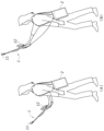
- FIG. 1 is an explanatory diagram showing a situation of a photographing operation performed by a user using the photographing system according to the first embodiment; An explanatory diagram showing a standard shooting state and a high-altitude shooting state.
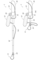
- FIG. 1 is a perspective view showing a support for the imaging device; A side view showing the expansion and contraction state of the support of the imaging device.
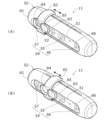
- FIG. 1 is a perspective view showing a sensor unit of an imaging device.
- FIG. 1 is a block diagram showing a schematic configuration of a photographing device and a control device. A block diagram showing an overview of the processing performed by the processor of the control device.
- FIG. 13 is an explanatory diagram showing a list of photographed data displayed on a display of a control device.
- FIG. 13 is an explanatory diagram showing a shooting standby screen displayed on a touch panel display of the shooting device.
- FIG. 13 is an explanatory diagram showing a screen displayed during shooting on a touch panel display of the shooting device.
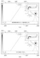
- FIG. 11 is an explanatory diagram showing the transition state of the available shooting time guide section on the shooting screen;
- FIG. 13 is an explanatory diagram showing the shooting screen with a message window displayed An explanatory diagram showing the contents and timing of messages displayed in the message window
- FIG. 13 is an explanatory diagram showing a confirmation screen for confirming the end of imaging, which is displayed on a touch panel display of the imaging device;
- FIG. 13 is an explanatory diagram showing a self-position lost notification screen displayed on a touch panel display of the imaging device;
- the first invention made to solve the above problem is an imaging device that images a location to be measured in order to perform a three-dimensional measurement process that generates three-dimensional spatial information of the location to be measured, and includes a sensor unit including a camera that images the location to be measured, a display input panel unit including a touch panel display that displays a screen to assist the user in the imaging operation and detects screen operations by the user, and a rod-shaped support body that supports the sensor unit and the display input panel unit, the support body having a grip portion that the user holds with one hand, the sensor portion being fixed to the end of the support body opposite the grip portion, and the display input panel portion being fixed to a position on the support body between the grip portion and the sensor portion.
- a sensor unit including a camera that images the location to be measured
- a display input panel unit including a touch panel display that displays a screen to assist the user in the imaging operation and detects screen operations by the user
- a rod-shaped support body that supports the sensor unit and the display input panel unit, the support body having
- the support has an extendable rod portion that changes the position of the sensor portion relative to the grip portion.
- the overall length of the imaging device is shortened, making it easier to carry and store the imaging device when not in use.
- the third invention further includes a cable that connects the sensor unit and the display input panel unit.
- the sensor unit and the display input panel unit are connected via a cable, so the sensor unit and the display input panel unit can be placed apart.
- the display input panel unit includes a first connection terminal to which a first cable that connects the sensor unit and the display input panel unit is detachably coupled, and a second connection terminal to which a second cable that connects a control device that controls the device itself and the display input panel unit is detachably coupled.
- the display input panel unit may include a repeater that relays data communication between the control device and the sensor unit, and the second cable may be used for data communication between the control device and the display input unit and for data communication between the control device and the sensor unit.
- the sixth invention further includes a wireless communication unit that wirelessly communicates with an information processing device that generates display information for displaying a screen that assists the user in taking photographs on the touch panel display, and the wireless communication unit is configured to transmit photographing information including an image taken by the camera and to receive the display information from the information processing device.
- the information processing device is placed in an appropriate location for use. This eliminates the inconvenience of the user having to constantly carry the information processing device, for example by hanging it on their shoulder, while taking pictures, as occurs when the photographing device is connected to the information processing device via a wire.
- the seventh invention is configured such that the camera takes color photographs, and the sensor unit has a neutral density filter that is movable between a position that covers the lens of the camera and a position that does not cover the lens of the camera.
- the eighth invention made to solve the above problem is an imaging system that includes an imaging device that images the location to be measured and a processor that controls the imaging device in order to perform 3D measurement processing to generate 3D spatial information of the location to be measured
- the imaging device includes a sensor unit including a camera that images the location to be measured, a display input panel unit including a touch panel display that displays a screen to assist the user in the imaging work and detects screen operations by the user, and a support body that supports the sensor unit and the display input panel unit, the support body having a grip part that the user holds in one hand, the display input panel unit being disposed in the vicinity of the grip part, and the processor being configured to display on the touch panel display at least an operation screen on which the user gives an instruction to start imaging.
- the imaging device By holding the grip part with one hand, the imaging device can be held stably with one hand, and the other hand can be used to easily operate the touch panel display to give instructions and make settings related to imaging.
- the processor that controls the imaging device may be provided in a control device separate from the imaging device, or may be provided in the imaging device itself.
- the ninth invention is configured such that the processor causes the touch panel display to display, as the operation screen, a shooting standby screen, a shooting in progress screen, and a shooting end confirmation screen in a sequential manner in response to a user's instruction.
- the tenth invention is configured such that the processor displays the shooting standby screen including an operation unit that allows the user to select one of a plurality of shooting modes having different control conditions for the camera.
- the processor is configured to notify the user of the saving of the captured image data and the return to the capture standby screen when capture ends, and to display the capture end confirmation screen including an operation unit for the user to input confirmation.
- the sixteenth invention is configured such that the processor detects a connection failure on the communication path between the camera and the touch panel display and the processor, and causes the touch panel display to display a screen notifying the user of the occurrence of the connection failure.
- this allows the user to hold the imaging device stably in one hand by grasping the grip portion with the other hand, and therefore allows the user to easily operate the touch panel display to give instructions and make settings regarding imaging with the other hand.
- the control device 2 is configured as a laptop or tablet PC that can be carried by the user (worker). In the example shown in FIG. 1, the control device 2 is stored in a shoulder bag and can be carried by the user, but the manner in which the user carries the control device 2 is not limited to this.
- the user holds the imaging device 1 in his/her hand and walks through the location to be measured, causing the imaging device 1 to capture images of the location to be measured. At this time, the user can change the position (height) of the sensor unit 11 by moving the arm holding the imaging device 1.
- the user can take a picture by positioning the sensor unit 11 at approximately the same height as the user's eye level by extending the arm holding the imaging device 1 slightly forward (standard imaging state).
- the user can take a picture by positioning the sensor unit 11 at a higher position than the user's eye level by raising the arm holding the imaging device 1 (high altitude imaging state).
- Figure 3 is a perspective view showing the support 13.
- Figure 4 is a side view showing the expansion and contraction state of the support 13.
- the support 13 of the imaging device 1 includes a main body 31, an extendable rod 32, a sensor mounting section 33, a panel mounting section 34, and a grip section 35.
- the display input panel section 12 includes a touch panel display 36.
- the panel mounting section 34 is provided on the main body section 31.
- the panel mounting section 34 includes a joint 41 (ball joint) that connects the display input panel section 12 and the main body section 31.
- the joint 41 can change the orientation of the display input panel section 12, that is, the orientation of the display surface of the touch panel display 36.
- the display input panel section 12 can perform a tilt operation that changes the orientation of the display input panel section 12 up and down and a pan operation that changes the orientation of the display input panel section 12 left and right by rotating the display input panel section 12 around two axes A1 and A2 that pass through the center of the joint 41 (ball joint).
- the panel mounting section 34 is also provided with a fixing knob 42. The user can fix the orientation of the display input panel section 12 by operating the fixing knob 42.
- the joint 41 is a ball joint, the orientation of the display input panel section 12 can be adjusted to any direction within a predetermined angle range.
- the user can adjust the orientation of the display input panel unit 12 as appropriate, improving the visibility and operability of the touch panel display 36.
- adjusting the orientation of the display input panel unit 12 in the tilt direction makes it easier to view and operate the screen of the touch panel display 36.
- adjusting the orientation of the display input panel unit 12 in the pan direction so that the screen of the touch panel display 36 faces to the left, where the user's face and left hand that operates the screen are located, makes it easier to view and operate the screen of the touch panel display 36.
- the sensor mounting section 33 is provided at the tip of the telescopic rod section 32.
- the sensor mounting section 33 has a joint 43 (hinge joint) that connects the sensor section 11 to the tip of the telescopic rod section 32.
- This joint 43 allows the orientation of the sensor section 11 to be changed.
- the sensor section 11 can be caused to perform a tilting operation that changes the orientation of the sensor section 11 up and down by rotating the sensor section 11 around the central axis A3 of the joint 43 (hinge joint).
- the sensor mounting section 33 is provided with a fixing knob 44. The user can fix the orientation of the sensor section 11 by operating the fixing knob 44.
- the display input panel unit 12 can be tilted and panned by the joint 41 made of a ball joint in the panel mounting portion 34, but the display input panel unit 12 may be tilted and panned by a combination of multiple hinge joints.
- the joint 43 in the sensor mounting section 33 is a hinge joint, which allows only a tilting motion to change the orientation of the sensor section 11 up and down, but it may also allow a panning motion to change the orientation of the sensor section 11 left and right.
- the joint 43 may be a ball joint or a combination of multiple hinge joints.
- the telescopic rod section 32 is configured to be telescopic in the axial direction.
- the telescopic rod section 32 has a structure in which multiple sheath tubes with gradually decreasing diameters are slidably connected.
- the user can change the position of the sensor portion 11 relative to the grip portion 35 held by the hand. That is, as shown in FIG. 4(A), when the telescopic rod portion 32 is extended (extended state), the sensor portion 11 is separated from the grip portion 35. This allows the sensor portion 11 to be positioned at a high position when photographing at high altitudes (see FIG. 2(B)).
- FIG. 4(B) when the telescopic rod portion 32 is retracted and most of the telescopic rod portion 32 is stored in the main body portion 31 (stored state), the overall length of the imaging device 1 is shortened, making it easier to carry and store the imaging device 1 when not in use.
- the user can hold the imaging device 1 stably in one hand by grasping the grip portion 35 with the hand. Therefore, the user can take pictures by orienting the sensor unit 11 in any direction by changing the orientation of the arm or body holding the imaging device 1 while taking pictures. In addition, the user can adjust the position of the sensor unit 11 by extending and retracting the extendable rod even while taking pictures, and can also adjust the orientation of the display input panel unit 12.
- the display input panel unit 12 is fixed to the main body unit 31, but the display input panel unit 12 may be fixed to the middle of the extendable rod unit 32 so that the position of the display input panel unit 12 relative to the grip unit 35 can be adjusted.
- the display input panel unit 12 may be fixed to the main body unit 31 via a movable member (not shown) separate from the extendable rod unit 32 to which the sensor unit 11 is fixed at its tip.
- Figure 5 is a perspective view showing the sensor unit 11.
- the sensor section 11 includes a sensor unit 51 and a sensor cover 52.
- the sensor unit 51 includes a visible camera 53 and a depth sensor 54.
- the visible camera 53 (color camera) captures color images of the subject.
- the depth sensor 54 includes an infrared projector 55 and left and right infrared cameras 56, 57 (stereo cameras).
- the infrared projector 55 irradiates the subject with infrared light.
- the left and right infrared cameras 56, 57 detect the reflected light of the infrared light irradiated onto the subject.
- the depth sensor 54 may be a sensor capable of acquiring depth information using other methods, such as LiDAR (Light Detection And Ranging), in addition to a stereo camera.
- LiDAR Light Detection And Ranging
- the visible camera 53 In the sensor unit 51, the visible camera 53, the left and right infrared cameras 56 and 57, and the infrared projector 55 are arranged side by side (approximately horizontally).
- the housing of the sensor unit 51 is elongated in the horizontal direction.
- the sensor cover 52 has a cover body 61 and a filter member 62.
- the cover body 61 covers the sensor unit 51. During shooting, the sensor section 11 may collide with surrounding objects while the shooting device 1 is being moved, and the cover body 61 is provided to protect the sensor unit 51 from the impact of this collision.
- the cover body 61 has an opening 66 that exposes the cover glass on the front side of the visible camera 53, the infrared projector 55, and the infrared cameras 56 and 57.
- the filter member 62 is attached to the cover body 61 so as to be slidable in the longitudinal direction of the sensor unit 51, i.e., in the arrangement direction of the visible camera 53, the infrared projector 55, and the infrared cameras 56 and 57.
- the filter member 62 has a first ring portion 63 and a second ring portion 64.
- An ND (Neutral Density) filter 65 (neutral density filter) is attached to the first ring portion 63.
- the filter member 62 is slidably disposed between a first position shown in FIG. 5(A) and a second position shown in FIG. 5(B). A user can grasp the filter member 62 with his or her fingers and slide it. In the first position shown in FIG. 5(A), the ND filter 65 does not cover the visible camera 53. In the second position shown in FIG. 5(B), the ND filter 65 covers the visible camera 53.
- the first ring portion 63 to which the ND filter 65 is attached is positioned between the visible camera 53 and one of the infrared cameras 57, and the second ring portion 64 is positioned to surround the lens of one of the infrared cameras 57.
- the filter member 62 none of the visible camera 53, the infrared projector 55, and the infrared cameras 56 and 57 are covered by the filter member 62.
- the first ring portion 63 is positioned at a position corresponding to the visible camera 53, and the second ring portion 64 is positioned at a position between the visible camera 53 and one of the infrared cameras 57.
- the filter member 62 covers only the visible camera 53, and neither the infrared projector 55 nor the infrared cameras 56 and 57 are covered by the filter member 62.
- the filter member 62 When the second ring portion 64 hits the inner periphery of the opening of the cover body 61, the filter member 62 is positioned at the first position shown in FIG. 5(A).
- a groove (not shown) is formed on the underside of the cover body 61, extending in the direction of movement of the filter member 62.
- a protrusion on the filter member 62 fits into this groove, thereby defining the range of movement of the filter member 62 and positioning the filter member 62 at the second position shown in FIG. 5(B).
- the user adjusts the filter member 62 to the second position (see FIG. 5B) where the ND filter 65 covers the visible camera 53.
- the user adjusts the filter member 62 to the first position (see FIG. 5A) where the ND filter 65 does not cover the visible camera 53.
- This makes it possible to adjust the brightness of the entire photographed image by reducing the amount of light input to the camera when photographing outdoors. It is also possible to avoid the problem of the entire photographed image being colored purple.
- the visible camera 53 color camera
- FIG. 6 is a block diagram showing the general configuration of the photographing device 1 and the control device 2.
- FIG. 7 is a block diagram showing an overview of the processing performed by the processor 86 of the control device 2.
- the sensor unit 11 of the imaging device 1 includes a visible camera 53, a depth sensor 54, an IMU 71 (Inertial Measurement Unit), an input/output interface 72, and a connection terminal 73.
- IMU 71 Inertial Measurement Unit
- the visible camera 53 (color camera) takes color photographs and outputs color images.
- the depth sensor 54 outputs depth information (distance image) as the detection result based on the images captured by the left and right infrared cameras 56, 57 (see Figure 5).
- the IMU 71 detects the motion state of the device itself, specifically, the three-dimensional angular velocity and acceleration. Based on the detection results of the IMU 71, the position, orientation, and velocity of the sensor unit 11 can be detected.
- the input/output interface 72 inputs and outputs data to and from the control device 2 via the display input panel unit 12. Specifically, detection data from the visible camera 53, the depth sensor 54, and the IMU 71 is transmitted.
- the input/output interface 72 may be based on the USB (registered trademark) standard.
- the first cable 21 that connects the sensor unit 11 and the display input panel unit 12 is detachably connected to the connection terminal 73.
- the visible camera 53, the depth sensor 54, and the IMU 71 may not be integrated into the sensor unit 51 (see FIG. 5). Alternatively, the depth sensor 54 and the IMU 71 may be omitted, and only the visible camera 53 may be provided. Alternatively, either the depth sensor 54 or the IMU 71 may be provided, and the visible camera 53 may be provided.
- the display input panel section 12 of the imaging device 1 includes a touch panel display 36, a repeater 74, an input/output interface 75, a first connection terminal 76, and a second connection terminal 77.
- the touch panel display 36 displays screens and the like that assist the user in taking photographs, based on the control of the control device 2.
- the repeater 74 relays data communication between the control device 2 and the sensor unit 11.
- the repeater 74 may be a hub based on the USB (registered trademark) standard.
- the input/output interface 75 inputs and outputs data between the control device 2. Specifically, it receives display information, such as a screen that supports the user's photographing operation, from the control device 2.
- the input/output interface 75 may be based on the USB (registered trademark) standard.
- a first cable 21 that connects the sensor unit 11 and the display input panel unit 12 is detachably connected to the first connection terminal 76.
- a second cable 22 that connects the display input panel unit 12 and the control device 2 is detachably connected to the second connection terminal 87.
- the first cable 21 is used for data communication between the control device 2 and the sensor unit 11 via the display input panel unit 12.
- the shooting data (shooting information) output from the sensor unit 11 is transmitted to the control device 2.
- the shooting data includes the image captured by the visible camera 53, the detection result (distance information) of the depth sensor 54, the detection result of the IMU 71, and the shooting time.
- the second cable 22 is used for data communication between the control device 2 and the display input panel unit 12 and data communication between the control device 2 and the sensor unit 11.
- display information of the screen to be displayed on the touch panel display 36 is transmitted from the control device 2, and user operation information detected on the touch panel display 36 is transmitted to the control device 2.
- the shooting data details screen 121 is provided with an image display section 122 and a shooting date and time display section 123.
- the image display section 122 plays back the captured images (key frames) included in the shooting data in sequence.
- the shooting date and time display section 123 displays the shooting date and time of the captured image displayed in the image display section 122.
- a frame in which a large change in visibility appears is extracted as a key frame, and the key frame is reflected in the point cloud.
- the point cloud generation process P14 is cancelled, and the screen returns to the shooting data details screen 121 (see FIG. 9).
- the point cloud generation process P14 is completed, the screen returns to the shooting data details screen 121.
- Figure 12 is an explanatory diagram showing the setting screen 181.
- a setting screen 181 shown in FIG. 12 (A) pops up on the shooting data list screen 101.
- the setting screen 181 also has a camera setting section 183.
- the camera setting section 183 has input sections 192, 193, and 194 for the resolution of the visible camera 53, the resolution of the depth sensor 54, and the frame rate of the visible camera 53.
- a pull-down menu (not shown) is displayed. The user can select the resolution of the visible camera 53, the resolution of the depth sensor 54, and the frame rate of the visible camera 53 in the pull-down menu.
- the setting screen 181 also has a device information display section 184.
- information related to the sensor unit 51 is displayed, including registration information for each item of the name (camera name), serial number, and firmware version of the sensor unit 51, as well as the date and time when the previous calibration process was performed.
- the device information display section 184 also has a "forced restart” button 195. When the user operates the “forced restart” button 195, the sensor unit 51 is forcibly restarted.
- the device information display section 184 also has an "execute” button 196. When the user operates the "execute” button 196, a device calibration screen 201 shown in FIG. 12(B) is popped up on the setting screen 181.
- the setting screen 181 also has a "Done” button 185.
- the setting process is executed based on the input contents on the setting screen 181, and the screen returns to the shooting data list screen 101 (see FIG. 8).
- the device calibration screen 201 displays a message encouraging the user to keep the image capture device 1 still in a stable location for a specified time for the calibration process, and the remaining time.
- the device calibration screen 201 also displays a progress bar 202 indicating the progress of the calibration process.
- the device calibration screen 201 also has a "Cancel" button 203. When the user operates the "Cancel" button 203, the calibration process is cancelled and the screen returns to the setting screen 181 (see FIG. 12(A)). When the calibration process is completed, the screen returns to the setting screen 181.
- FIG. 13 is an explanatory diagram showing the pause screen 221.
- Figure 14 is an explanatory diagram showing the poor connection notification screens 231 and 241.
- the screen transitions to the pause screen 221 shown in FIG. 13.
- the pause screen 221 displays a message indicating that the mode has been switched to shooting mode, and a message indicating that the screen can be displayed and operated on the display 82 of the control device 2 by performing an operation to end the shooting mode on the screen displayed on the touch panel display 36 of the shooting device 1.
- a poor connection notification screen 231, 241 (error screen) shown in FIG. 14 will pop up on the shooting data list screen 101 depending on the cause of the failure.
- the poor connection notification screen 231 shown in FIG. 14 (A) will be displayed.
- the poor connection notification screen 241 shown in FIG. 14 (B) will be displayed.
- a pause screen 301 is displayed on the touch panel display 36 of the photographing device 1.
- the pause screen 301 displays a message indicating that the device is in non-photographing mode, i.e., that the display 82 of the control device 2 is displaying and operating the photographing data list screen 101 (see FIG. 8 ).
- the pause screen 301 also displays a message indicating that the device will switch to photographing mode by performing an operation to start photographing on the screen displayed on the display 82 of the control device 2.
- the shooting standby screen 311 has an image display section 312.
- the image display section 312 displays the image captured by the visible camera 53 in real time.
- the shooting standby screen 311 also has a shooting mode selection section 313.
- a pull-down menu 314 is displayed as shown in FIG. 16(B).
- the pull-down menu 314 allows the user to select from a number of shooting modes with different control conditions (processing conditions for image signal processing) for the visible camera 53.
- the user can select from "indoor” (indoor shooting mode), "outdoor” (first outdoor shooting mode), or "outdoor + ND filter” (second outdoor shooting mode) as the shooting mode.
- the brightness correction table used in image signal processing image correction processing
- image correction processing differs in each shooting mode.
- the shooting standby screen 311 also has a brightness adjustment bar 315.
- the user can adjust the brightness of the captured image by operating the slider of the brightness adjustment bar 315. Brightness adjustment can be performed separately for each shooting mode.
- the shooting standby screen 311 also has a shooting start button 316.
- shooting start button 316 When the user operates the shooting start button 316, shooting starts and the screen transitions to a shooting in progress screen 331 (see FIG. 17).
- the shooting standby screen 311 also has an "End shooting” button 317.
- the shooting mode ends, the mode switches to a non-shooting mode, and the screen transitions to the pause screen 301 (see FIG. 15).
- FIG. 17 is an explanatory diagram showing the shooting screen 331.
- FIG. 18 is an explanatory diagram showing the transition status of the shooting time guide section 336 on the shooting screen 331.
- FIG. 19 is an explanatory diagram showing the shooting screen 331 with a message window 337 displayed.
- FIG. 20 is an explanatory diagram showing the contents of the message displayed in the message window 337 and the display timing.
- the shooting screen 331 has a main window 332 (first image display frame) and a sub-window 333 (second image display frame).
- the main window 332 and the sub-window 333 have different display magnifications, with the main window 332 displaying an enlarged image and the sub-window 333 displaying a reduced image.
- the main window 332 and sub window 333 also display either a real-time image 341 captured by the visible camera 53 or a shooting path image 342 that represents the shooting path at the location to be measured.
- the shooting path image 342 is obtained by superimposing a line 344 representing the shooting path on a point cloud image 343 that represents the location to be measured.
- the point cloud image is an image (rendering) of each point of the generated point cloud data as viewed from a specified viewpoint.
- FIG. 17(A) is in the standard state.
- the shooting image 341 is displayed enlarged in the main window 332, and the shooting path image 342 is displayed reduced in the sub-window 333.
- the example shown in FIG. 17(B) is in the expanded shooting path state.
- the shooting path image 342 is displayed enlarged in the main window 332, and the shooting image 341 is displayed reduced in the sub-window 333.
- the user can switch between the standard state shown in FIG. 17(A) and the expanded shooting path state shown in FIG. 17(B) by operating the sub-window 333. That is, when the sub-window 333 is operated in the standard state shown in FIG. 17(A), the state transitions to the expanded shooting path state shown in FIG. 17(B), and the shooting path image 342 is enlarged and displayed in the main window 332. Also, when the sub-window 333 is operated in the expanded shooting path state shown in FIG. 17(B), the state transitions to the standard state shown in FIG. 17(A), and the shooting image 341 is enlarged and displayed in the main window 332.
- a mesh image may be superimposed on the captured image 341 within the point cloud generation range.
- the mesh image can be obtained by converting the generated point cloud data into mesh data and then performing processing to image the mesh data with the same angle of view as the captured image 341.
- the shooting screen 331 also has a speed bar 334.
- the speed bar 334 visualizes and displays the speed at which the user moves the sensor unit 11. Specifically, the speed is expressed by color. For example, the speed bar 334 is drawn with a gradation from green to orange, with the proportion of orange increasing as the speed increases. This allows the user to easily check whether the speed at which the sensor unit 11 is moved is appropriate, specifically, whether the speed at which the sensor unit 11 is moved is not too fast. This makes it possible to prevent the user from moving the sensor unit 11 too fast, which causes blurring and reduces the accuracy of the three-dimensional measurement.
- the shooting screen 331 also has an elapsed time display section 335.
- the elapsed time display section 335 displays the time that has elapsed since shooting began up to the present.
- a shooting time guide section 336 is displayed on the shooting in progress screen 331. Whereas the elapsed time display section 335 is constantly displayed, the shooting time guide section 336 is displayed only for a predetermined period of time at a predetermined timing. Note that the shooting time guide section 336 is not limited to being displayed only for a predetermined period of time, but can be set to be constantly displayed by the user's operation.
- the shooting time guide 336 is displayed for a predetermined time (e.g., 5 seconds) from the start of shooting.
- the shooting time guide 336 displays the available shooting time (e.g., 15 minutes).
- the shooting time indicator 336 is displayed for a predetermined time (e.g., 5 seconds). In this case, the remaining shooting time is displayed in the shooting time indicator 336.
- the timing for displaying the shooting time indicator 336 is not limited to once. For example, the shooting time indicator 336 may be displayed when the remaining shooting time is 3 minutes and when the remaining shooting time is 2 minutes.
- the shooting time indicator 336 continues to be displayed until the remaining shooting time runs out.
- the shooting time indicator 336 displays the remaining shooting time.
- the shooting time indicator 336 is displayed in a manner different from the state shown in FIG. 18(A) and (B). For example, the shooting time indicator 336 is highlighted by changing the color of the background and frame of the shooting time indicator 336.
- a message window 337 is displayed on the shooting screen 331. Messages to notify the user are displayed in the message window 337. Specifically, messages regarding shooting instructions and various warnings are displayed.
- the example shown in FIG. 19 (A) is an information message.
- Information messages provide the user with information that is helpful for the user's shooting work or information that calls attention to the user's attention.
- the example shown in FIG. 19 (B) is a warning message. Warning messages prompt the user to take action to improve the state of shooting work that needs to be improved immediately.
- the message window 337 may be displayed at a different position on the shooting screen 331 depending on the type of message (information, warning, etc.). For example, in the example shown in FIG. 19(B), the message window 337 for a warning message is displayed at the bottom of the shooting screen 331, similar to the information message shown in FIG. 19(A), but the warning message may also be displayed in the center of the shooting screen 331 so that the user can immediately check it.
- FIG. 20 shows examples of information messages and warning messages displayed in the message window 337.
- Information messages include a message indicating successful recovery from a self-position loss, a message indicating completion of position correction processing when loop closing (circular movement) is detected, and a message urging the user to stop the image capture device 1 for position correction processing when loop closing is detected.
- Warning messages include a message urging the user to stop the image capture device 1 if the user moves the image capture device 1 while loop closing is detected and position correction processing is being performed, a message urging the user to move the image capture device 1 slowly if the user is moving the image capture device 1 too quickly, a message urging the user to change the subject to be captured if few feature points are extracted from the captured image, and a message urging the user to maintain an appropriate distance from the subject if the user gets too close.
- Figure 21 is an explanatory diagram showing the end-of-shooting confirmation screens 351, 361.
- an end shooting button 339 is provided on the shooting-in-progress screen 331.
- a process for ending shooting and saving the captured data is executed, and a shooting end confirmation screen 351 is popped up on the shooting-in-progress screen 331, as shown in FIG. 21 (A).
- the end-of-shooting confirmation screen 351 displays a message that shooting has ended and the shooting data has been saved, and a message that returns to the shooting standby screen 311 (see FIG. 16).
- the end-of-shooting confirmation screen 351 also has an "OK" button 352. When the user operates the "OK” button 352, the screen transitions to the shooting standby screen 311.
- shooting time (the time elapsed from the start of shooting) exceeds a predetermined available shooting time
- shooting is forcibly ended and a process for saving the shooting data is executed.
- a confirmation screen 361 for ending shooting due to shooting time exceeding is popped up on the shooting in progress screen 331.
- the end of shooting confirmation screen 361 displays a message that shooting has been forcibly ended due to the time limit being exceeded and that the shooting data has been saved, and a message that the screen will return to the shooting standby screen 311 (see FIG. 16).
- the end of shooting confirmation screen 361 also has an "OK" button 362. When the user operates the "OK” button 362, the screen transitions to the shooting standby screen 311.
- shooting is forcibly terminated when the shooting time exceeds a predetermined shooting time, but such forced termination may not be performed, and the user may be allowed to select a mode in which forced termination is performed and a mode in which forced termination is not performed.
- Fig. 22 is an explanatory diagram showing a self-position lost notification screen 371.
- Fig. 23 is an explanatory diagram showing a recovery in progress screen 381.
- Fig. 24 is an explanatory diagram showing a last position acquisition point enlarged screen 391.
- Fig. 25 is an explanatory diagram showing a recovery failure notification screen 401.
- a self-location loss may occur in which the self-location is lost during tracking processing P12 (self-location estimation processing).
- tracking processing P12 self-location estimation processing
- a self-location lost notification screen 371 is popped up on the shooting screen 331 on the touch panel display 36 of the image capture device 1, as shown in FIG. 22.
- the self-location lost notification screen 371 notifies the user that the self-location has been lost and displays a message urging the user to return to the point where the last location was acquired.
- the self-location lost notification screen 371 also has an "OK" button 372. When the user operates the "OK” button 372, the screen transitions to a returning screen 381 shown in FIG. 23. At this time, the processor 86 of the control device 2 starts a process to detect that the image capture device 1 has returned to the point where the last location was acquired.
- the example shown in Fig. 23(A) is the standard state, similar to the example shown in Fig. 17(A), where an image 341 captured by the visible camera 53 is displayed in an enlarged form in the main window 332 (first image display frame), and a shooting path image 342 is displayed in a reduced form in the sub-window 333 (second image display frame).
- the example shown in Fig. 23(B) is the enlarged shooting path state, similar to the example shown in Fig. 17(B), where an image capture path image 342 is displayed in an enlarged form in the main window 332, and a captured image 341 is displayed in a reduced form in the sub-window 333.
- the return screen 381 is provided with another sub-window 382 (third image display frame).
- the photographed image of the final position acquisition point is displayed in the sub-window 382. This allows the user to easily grasp the final position acquisition point.
- the recovery screen 381 also displays a message window 383. Similar to the self-location lost notification screen 371 (see FIG. 22), the message window 383 displays a message notifying the user that their own location has been lost and encouraging them to return to the point where their last location was obtained.
- a last position acquisition point enlarged screen 391 is popped up on the returning screen 381, as shown in FIG. 24.
- the last position acquisition point enlarged screen 391 displays an enlarged image of the last position acquisition point.
- an "X" button 392 is displayed on the last position acquisition point enlarged screen 391.
- the screen will transition to the shooting screen 331 (see FIG. 17).
- a message notifying the user that the device has returned to the last location acquisition point may be displayed on the returning screen 381, and then the screen may transition to the shooting screen 331.
- a recovery failure notification screen 401 is popped up on the recovering screen 381, as shown in FIG. 25.
- the recovery failure notification screen 401 displays a message indicating that recovery from a state where its own position has been lost has failed ("Tracking recovery has failed.”).
- the recovery failure notification screen 401 also has an "OK" button 402. When the user operates the "OK” button 402, shooting is forcibly terminated, and the screen transitions to the shooting standby screen 311 (see FIG. 16).
- Figure 26 is an explanatory diagram showing the poor connection notification screen 411.
- a poor connection notification screen 411 (error screen) shown in FIG. 26 is displayed as a pop-up on the shooting screen 331.
- the poor connection notification screen 411 displays a message to the effect that the sensor unit 11, including the visible camera 53, cannot be detected, and a message urging the user to check the condition of the sensor unit 11 and the cable connecting the display input panel unit 12 and the sensor unit 11.
- the poor connection notification screen 411 is provided with a "retry” button 412 and a “cancel” button 413.
- the user operates the "retry” button 412 after performing the work to resolve the poor connection of the cable connecting the display input panel unit 12 and the sensor unit 11 of the image capture device 1.
- the screen transitions to the image capture standby screen 311 (see FIG. 16).
- the screen transitions from the image capture mode to the list mode.
- the touch panel display 36 of the image capture device 1 transitions to the pause screen 301 (see FIG. 15).
- the display 82 of the control device 2 transitions from the pause screen 221 (see FIG. 13) to the image capture data list screen 101 (see FIG. 8).
- the second cable 22 connecting the display input panel unit 12 of the imaging device 1 and the control device 2 may become disconnected. In this case, the screen will no longer be displayed on the touch panel display 36 of the imaging device 1.
- a screen (not shown) notifying the user of the poor connection is popped up on the pause screen 221 (see FIG. 13).
- the screen notifying the user of the poor connection has an "OK" button. When the user operates the "OK” button, the screen transitions to the imaging data list screen 101 (see FIG. 8).
- FIG. 27 is an explanatory diagram showing the shooting mode end confirmation screen 421.
- the shooting mode end confirmation screen 421 displays a message asking the user whether or not to end the shooting mode and return to the list mode.
- the shooting mode end confirmation screen 421 also has an "OK" button 422 and a "Cancel” button 423.
- the screen returns to the shooting standby screen 311 (see FIG. 16).
- the shooting mode ends and the screen returns to the list mode.
- the touch panel display 36 of the shooting device 1 transitions to the pause screen 301 (see FIG. 15).
- the display 82 of the control device 2 transitions from the pause screen 221 (see FIG. 13) to the shooting data list screen 101 (see FIG. 8).
- Fig. 28 is a block diagram showing a schematic configuration of an image capture device 1 and a control device 2 according to the second embodiment.
- the photographing device 1 and the control device 2 are connected by wire, but in this embodiment, the photographing device 1 and the control device 2 are connected wirelessly.
- the photographing device 1 has a wireless communication unit 78.
- the control device 2 (information processing device) has a wireless communication unit 88.
- the wireless communication unit 78 of the photographing device 1 and the wireless communication unit 88 of the control device 2 perform wireless communication using an appropriate wireless communication method such as wireless LAN.
- an input/output interface 79 is provided to input and output data between the sensor unit 11, which has the same configuration as in the first embodiment.
- the control device 2 can be placed in an appropriate location, such as the location to be measured or nearby, during imaging, eliminating the need for the user to carry the control device 2 around with them.
- the photography system is composed of the photography device 1 held by the user in the hand and the control device 2 carried by the user, but the display input panel unit 12 of the photography device 1 may be configured to include all or part of the functions of the control device 2.
- the process of generating simple point cloud data for the user to check the photography situation may be performed by the photography device 1, since it is a relatively small load and needs to be performed in real time during photography.
- the process of generating regular point cloud data to be obtained as a 3D measurement result is a relatively large load and only needs to be performed after photography, so it may be performed by a separately provided server device with high processing capabilities.
- control device 2 may be configured on-premise or in the cloud.
- server device may be configured on-premise or in the cloud.
- the imaging device disclosed herein has the effect of allowing the user to easily continue imaging without placing a heavy burden on the user, even when the imaging range is wide or imaging from high places is required, and is useful as an imaging device for imaging a measurement target location in order to perform three-dimensional measurement processing that generates three-dimensional spatial information of the measurement target location.
- Photographing device 2 Control device (information processing device) 11: Sensor section 12: Display input panel section 13: Support 21: First cable 22: Second cable 31: Main body section 32: Telescopic rod section 33: Sensor mounting section 34: Panel mounting section 35: Grip section 36: Touch panel display 41: Joint 42: Fixed knob 43: Joint 44: Fixed knob 51: Sensor unit 52: Sensor cover 53: Visible camera 54: Depth sensor 61: Cover body 62: Filter member 65: ND filter 101: Shooting data list screen 121: Shooting data details screen 231: Connection failure notification screen 241: Connection failure notification screen 311: Shooting standby screen 331: Shooting in progress screen 335: Elapsed time display section 336: Shooting time guide section 351: Shooting end confirmation screen 361: Shooting end confirmation screen 371: Self-position lost notification screen 381: Recovery in progress screen 411: Connection failure notification screen 421: Shooting mode end confirmation screen
Landscapes
- Engineering & Computer Science (AREA)
- Multimedia (AREA)
- Signal Processing (AREA)
- Physics & Mathematics (AREA)
- General Physics & Mathematics (AREA)
- Radar, Positioning & Navigation (AREA)
- Remote Sensing (AREA)
- Studio Devices (AREA)
Abstract
【課題】撮影範囲が広範囲に及ぶ場合や、高所撮影が必要な場合などにおいても、ユーザに大きな負担を強いることなくユーザが容易に撮影を継続できるようにする。 【解決手段】計測対象場所を撮影するカメラを含むセンサ部11と、ユーザの撮影作業を支援する画面を表示する共にユーザによる画面操作を検出するタッチパネルディスプレイ36を含む表示入力パネル部12と、センサ部および表示入力パネル部を支持する棒状の支持体13と、を備え、支持体は、ユーザが片手で把持するグリップ部35を有し、センサ部は、支持体におけるグリップ部とは相反する側の端部に固定され、表示入力パネル部は、支持体におけるグリップ部とセンサ部の間の位置に固定された。特に、支持体は、グリップ部に対するセンサ部の位置を変化させる伸縮ロッド部32を有する。また、表示入力パネル部は、パンおよびチルトの方向で向きを調整可能に支持体に固定される。
Description
本開示は、計測対象場所の3次元空間情報を生成する3次元計測処理を行うために、計測対象場所を撮影する撮影装置に関するものである。
計測対象物を撮影した撮影画像に基づいて、3次元空間上に計測対象物を表す点群を生成する3次元計測の技術が知られている。この3次元計測では、近年、SLAM(Simultaneous Localization And Mapping)法が注目されている。SLAM法では、移動体(例えば作業者)に撮影装置を保持させて計測対象物を種々の方向から撮影した撮影画像に基づいて、自機の位置情報を取得する自己位置推定と、3次元空間上に計測対象物を表す点群を生成するマッピングとが行われる。
このようなSLAM法に関連する技術として、従来、ユーザが保持した撮影装置(センサ)の移動方向や移動速度を表す矢印の画像や、計測済み領域の方向と未計測領域の方向とを識別する画像により、撮影が不十分なエリアをユーザに提示する技術が知られている(特許文献1参照)。
従来の技術によれば、計測対象場所を撮影する撮影装置として、距離センサ及び可視カメラが搭載されたタブレットPC(計測装置本体)が用いられ、ユーザが撮影装置を両手で保持して計測対象場所内を歩くことで計測対象場所の撮影が行われる。
このような撮影装置でも、撮影範囲が狭く、比較的短時間で撮影を終えることができる場合には支障は少ない。しかしながら、撮影範囲が広範囲に及ぶ場合があり、このような場合には、ユーザの負担が大きいため、ユーザの負担を軽減できる構成が望まれる。また、人物の視点より高い位置から撮影する高所撮影が必要な場合があり、このような場合には、高所撮影をユーザが容易に行える構成が望まれる。
そこで、本開示は、撮影範囲が広範囲に及ぶ場合や、高所撮影が必要な場合などにおいても、ユーザに大きな負担を強いることなくユーザが容易に撮影を継続することができる撮影装置を提供することを主な目的とする。
本開示の撮影装置は、計測対象場所の3次元空間情報を生成する3次元計測処理を行うために、計測対象場所を撮影する撮影装置であって、計測対象場所を撮影するカメラを含むセンサ部と、ユーザの撮影作業を支援する画面を表示する共にユーザによる画面操作を検出するタッチパネルディスプレイを含む表示入力パネル部と、前記センサ部および前記表示入力パネル部を支持する棒状の支持体と、を備え、前記支持体は、ユーザが片手で把持するグリップ部を有し、前記センサ部は、前記支持体における前記グリップ部と相反する側の端部に固定され、前記表示入力パネル部は、前記支持体における前記グリップ部と前記センサ部の間の位置に固定された構成とする。
本開示によれば、一方の手でグリップ部を把持することで、片手で撮影装置を安定して保持することができる。また、センサ部と表示入力パネル部とが別々に配置されるため、ユーザが見やすいように表示入力パネル部を手元に配置したまま、センサ部を手元から離れた位置に配置することができる。これにより、撮影範囲が広範囲に及ぶ場合や、高所撮影が必要な場合などにおいても、ユーザに大きな負担を強いることなくユーザが容易に撮影を継続することができる。
前記課題を解決するためになされた第1の発明は、計測対象場所の3次元空間情報を生成する3次元計測処理を行うために、計測対象場所を撮影する撮影装置であって、計測対象場所を撮影するカメラを含むセンサ部と、ユーザの撮影作業を支援する画面を表示する共にユーザによる画面操作を検出するタッチパネルディスプレイを含む表示入力パネル部と、前記センサ部および前記表示入力パネル部を支持する棒状の支持体と、を備え、前記支持体は、ユーザが片手で把持するグリップ部を有し、前記センサ部は、前記支持体における前記グリップ部と相反する側の端部に固定され、前記表示入力パネル部は、前記支持体における前記グリップ部と前記センサ部の間の位置に固定された構成とする。
これによると、一方の手でグリップ部を把持することで、片手で撮影装置を安定して保持することができる。また、センサ部と表示入力パネル部とが別々に配置されるため、ユーザが見やすいように表示入力パネル部を手元に配置したまま、センサ部を手元から離れた位置に配置することができる。これにより、撮影範囲が広範囲に及ぶ場合や、高所撮影が必要な場合などにおいても、ユーザに大きな負担を強いることなくユーザが容易に撮影を継続することができる。
また、第2の発明は、前記支持体は、前記グリップ部に対する前記センサ部の位置を変化させる伸縮ロッド部を有する構成とする。
これによると、ユーザが、撮影時に状況に応じて適宜にグリップ部に対するセンサ部の位置を調整することができる。また、伸縮ロッド部を縮めることで撮影装置の全長が短くなるため、不使用時の撮影装置の持ち運びや保管が容易になる。
また、第3の発明は、更に、前記センサ部と前記表示入力パネル部とを接続するケーブルを備える構成とする。
これによると、センサ部と表示入力パネル部とがケーブルを介して接続されるため、センサ部と表示入力パネル部とを離して配置することができる。
また、第4の発明は、前記表示入力パネル部は、パンおよびチルトの少なくともいずれかの方向で向きを調整可能に前記支持体に固定される構成とする。
これによると、ユーザが、適宜に表示入力パネル部の向きを調整することができるため、タッチパネルディスプレイの画面の閲覧や操作が容易になる。
また、第5の発明は、前記表示入力パネル部は、前記センサ部と前記表示入力パネル部とを接続する第1のケーブルが着脱可能に結合される第1の接続端子と、自装置を制御する制御装置と前記表示入力パネル部とを接続する第2のケーブルが着脱可能に結合される第2の接続端子と、を備える構成とする。
これによると、撮影装置の取り扱いが容易になる。この場合、表示入力パネル部が、制御装置とセンサ部との間のデータ通信を中継する中継器を備え、第2のケーブルが、制御装置と表示入力部との間のデータ通信と、制御装置とセンサ部との間のデータ通信とに利用される構成でもよい。
また、第6の発明は、更に、ユーザの撮影作業を支援する画面を前記タッチパネルディスプレイに表示させるための表示情報を生成する情報処理装置と無線通信を行う無線通信部を備え、前記無線通信部は、前記カメラによる撮影画像を含む撮影情報を送信すると共に、前記表示情報を前記情報処理装置から受信する構成とする。
これによると、情報処理装置が適宜な場所に静置して使用される。このため、撮影装置が情報処理装置と有線接続されている場合のように、撮影中にユーザが情報処理装置を肩にかけるなどして常時携行する面倒が解消される。
また、第7の発明は、前記カメラは、カラー撮影を行い、前記センサ部は、前記カメラのレンズを覆う位置と、前記カメラのレンズを覆わない位置との間で移動可能に設けられた減光フィルタを有する構成とする。
これによると、カメラに入力される光量を抑えることで撮影画像全体の明るさを調整することができる。また、カメラの特性により明るい環境で撮影画像全体に着色が発生する不具合を避けることができる。
前記課題を解決するためになされた第8の発明は、計測対象場所の3次元空間情報を生成する3次元計測処理を行うために、計測対象場所を撮影する撮影装置と、その撮影装置を制御するプロセッサとを備えた撮影システムであって、前記撮影装置は、計測対象場所を撮影するカメラを含むセンサ部と、ユーザの撮影作業を支援する画面を表示する共にユーザによる画面操作を検出するタッチパネルディスプレイを含む表示入力パネル部と、前記センサ部および前記表示入力パネル部を支持する支持体と、を備え、前記支持体は、ユーザが片手で把持するグリップ部を有し、前記表示入力パネル部は、前記グリップ部の近傍に配置され、前記プロセッサは、少なくとも撮影の開始の指示をユーザが行う操作画面を前記タッチパネルディスプレイに表示させる構成とする。
これによると、一方の手でグリップ部を把持することで、片手で撮影装置を安定して保持することができるため、タッチパネルディスプレイでの撮影に関する指示や設定のための画面操作をもう一方の手で容易に行うことができる。なお、撮影装置を制御するプロセッサは、撮影装置とは別の制御装置に設けられたものでもよく、また、撮影装置自体に設けられたものでもよい。
また、第9の発明は、前記プロセッサは、前記操作画面として、撮影待機画面、撮影中画面、および撮影終了確認画面を、ユーザの指示に応じて順次遷移するように前記タッチパネルディスプレイに表示させる構成とする。
これによると、ユーザが、撮影前、撮影中、撮影終了時の各段階で必要な設定や確認を適切に行うことができる。
また、第10の発明は、前記プロセッサは、前記カメラの制御条件が異なる複数の撮影モードのいずれかをユーザが選択する操作部を含む前記撮影待機画面を表示させる構成とする。
これによると、ユーザが、撮影開始前に、計測対象場所の特徴に応じて撮影モードを指定することができる。この場合、屋内撮影モードと屋外撮影モードとのいずれかが選択できるようにしてもよい。さらに、減光フィルタの有無に応じた2つの屋外撮影モードのいずれかが選択できるようにしてもよい。
また、第11の発明は、前記プロセッサは、前記カメラによる撮影画像、および前記撮影装置が移動した経路を表す撮影経路画像のうち、いずれか一方の画像を拡大して表示する第1の画像表示枠と、いずれか他方の画像を縮小して表示する第2の画像表示枠と、前記第1の画像表示枠および前記第2の画像表示枠に表示させる画像を切り替える操作部とを含む前記撮影中画面を表示させる構成とする。
これによると、ユーザが、必要に応じて拡大して表示させる画像と縮小して表示させる画像とを切り替えることができる。なお、第2の画像表示枠自体が操作部であってもよい。
また、第12の発明は、前記プロセッサは、撮影終了時に、撮影データの保存および前記撮影待機画面への復帰をユーザに通知すると共に、ユーザが確認したことを入力する操作部を含む前記撮影終了確認画面を表示させる構成とする。
これによると、ユーザが、撮影が終了したことを容易に確認することができる。
また、第13の発明は、前記プロセッサは、ユーザが前記センサ部を動かす速度を計測して、その速度が適切である否かを可視化した画像を含む前記撮影中画面を表示させる構成とする。
これによると、ユーザが、センサ部を動かす速度が適切である否かを容易に把握することができる。
また、第14の発明は、前記プロセッサは、撮影開始時に、所定の撮影可能時間を含む前記撮影中画面を表示させ、撮影中に、撮影開始からの経過時間を前記撮影可能時間から差し引いた撮影残り時間が所定値以下になったタイミングで、前記撮影残り時間を含む前記撮影中画面を表示させる構成とする。
これによると、ユーザが、撮影開始時に撮影可能時間を把握することができ、また、撮影残り時間が少なくなったタイミングで撮影残り時間を把握することができる。
また、第15の発明は、前記プロセッサは、トラッキング処理で前記撮影装置の現在位置を見失う自己位置ロストを検知すると、その自己位置ロストの発生をユーザに通知すると共に、最終位置取得地点をユーザに提示して、最終位置取得地点に戻るようにユーザを促す画面を前記タッチパネルディスプレイに表示させる構成とする。
これによると、自己位置ロストが発生した場合に、ユーザが速やかに最終位置取得地点に戻って撮影をやり直すことができる。
また、第16の発明は、前記プロセッサは、前記カメラおよび前記タッチパネルディスプレイと前記プロセッサとの間の通信経路上の接続不良を検知し、その接続不良の発生をユーザに通知する画面を前記タッチパネルディスプレイに表示させる構成とする。
これによると、ユーザが、接続不良により撮影装置が正常に動作しないことを容易に把握することができる。
また、第17の発明は、計測対象場所の3次元空間情報を生成する3次元計測処理を行うために、計測対象場所を撮影する撮影装置であって、計測対象場所を撮影するカメラを含むセンサ部と、ユーザの撮影作業を支援する画面を表示する共にユーザによる画面操作を検出するタッチパネルディスプレイを含む表示入力パネル部と、前記センサ部および前記表示入力パネル部を支持する支持体と、を備え、前記支持体は、ユーザが片手で把持するグリップ部を有し、前記表示入力パネル部は、前記グリップ部の近傍に配置され、前記タッチパネルディスプレイは、少なくとも撮影の開始の指示をユーザが行う操作画面を表示する構成とする。
これによると、第8の発明と同様に、一方の手でグリップ部を把持することで、片手で撮影装置を安定して保持することができるため、タッチパネルディスプレイでの撮影に関する指示や設定のための画面操作をもう一方の手で容易に行うことができる。
また、第18の発明は、計測対象場所の3次元空間情報を生成する3次元計測処理を行うために、計測対象場所を撮影する撮影装置を制御する処理をプロセッサにより実行する撮影制御方法であって、計測対象場所を撮影するカメラを含むセンサ部と、ユーザの撮影作業を支援する画面を表示する共にユーザによる画面操作を検出するタッチパネルディスプレイを含む表示入力パネル部と、前記センサ部および前記表示入力パネル部を支持する支持体と、を備え、前記支持体は、ユーザが片手で把持するグリップ部を有し、前記表示入力パネル部は、前記グリップ部の近傍に配置された前記撮影装置における前記タッチパネルディスプレイに対して、少なくとも撮影の開始を指示する操作をユーザが行う操作画面を表示させる構成とする。
これによると、第8の発明と同様に、一方の手でグリップ部を把持することで、片手で撮影装置を安定して保持することができるため、タッチパネルディスプレイでの撮影に関する指示や設定のための画面操作をもう一方の手で容易に行うことができる。
以下、本開示の実施の形態を、図面を参照しながら説明する。
(第1実施形態)
図1は、第1実施形態に係る撮影システムを用いてユーザが行う撮影作業の状況を示す説明図である。図2は、標準撮影状態と高所撮影状態とを示す説明図である。
図1は、第1実施形態に係る撮影システムを用いてユーザが行う撮影作業の状況を示す説明図である。図2は、標準撮影状態と高所撮影状態とを示す説明図である。
図1に示すように、撮影システムは、撮影装置1と、制御装置2(情報処理装置)とを備えている。
撮影装置1は、センサ部11と、表示入力パネル部12と、棒状の支持体13とを備えている。撮影装置1のセンサ部11と表示入力パネル部12とは第1のケーブル21を介して接続されている。撮影装置1の表示入力パネル部12と制御装置2は第2のケーブル22を介して接続されている。
制御装置2は、ユーザ(作業者)が携行可能なラップトップ型やタブレット型のPCで構成される。図1に示す例では、制御装置2が肩掛け式のバッグに収納されてユーザが携行できるが、ユーザが制御装置2を携行する態様はこれに限定されない。
ユーザは、撮影装置1を手で保持して計測対象場所を歩きながら撮影装置1に計測対象場所の撮影を行わせる撮影作業を行う。このとき、ユーザは、撮影装置1を保持する腕を動かすことで、センサ部11の位置(高さ)を変化させることができる。
例えば、図2(A)に示すように、ユーザは、撮影装置1を保持した腕を僅かに前に出すことで、センサ部11をユーザの目線の高さと概ね同じ位置に配置して撮影を行うことができる(標準撮影状態)。一方、図2(B)に示すように、ユーザは、撮影装置1を保持した腕を上げることで、センサ部11をユーザの目線より高い位置に配置して撮影を行うことができる(高所撮影状態)。
次に、撮影装置1の支持体13について説明する。図3は、支持体13を示す斜視図である。図4は、支持体13の伸縮状況を示す側面図である。
図3に示すように、撮影装置1の支持体13は、本体部31と、伸縮ロッド部32と、センサ取付部33と、パネル取付部34と、グリップ部35とを備えている。表示入力パネル部12は、タッチパネルディスプレイ36を備えている。
パネル取付部34は、本体部31に設けられている。パネル取付部34は、表示入力パネル部12と本体部31とを連結するジョイント41(ボールジョイント)を備えている。このジョイント41により、表示入力パネル部12の向き、すなわち、タッチパネルディスプレイ36の表示面の向きを変化させることができる。具体的には、ジョイント41(ボールジョイント)の中心を通る2本の軸A1,軸A2を中心にして表示入力パネル部12が回転することにより、表示入力パネル部12の向きを上下に変化させるチルト動作と、表示入力パネル部12の向きを左右に変化させるパン動作とを表示入力パネル部12に行わせることができる。また、パネル取付部34には、固定ノブ42が設けられている。ユーザが固定ノブ42を操作することで、表示入力パネル部12の向きを固定させることができる。なお、図3に示す例では、ジョイント41がボールジョイントであるため、所定の角度範囲で表示入力パネル部12の向きを任意の方向に調整することができる。
このように、ユーザが適宜に表示入力パネル部12の向きを調整することができるため、タッチパネルディスプレイ36の視認性および操作性が向上する。例えば、高所撮影の場合などで、棒状の支持体13の角度を変える場合には、表示入力パネル部12の向きをチルト方向に調整すると、タッチパネルディスプレイ36の画面の閲覧や操作が容易になる。また、例えば、ユーザが撮影装置1を右手で保持した場合、タッチパネルディスプレイ36の画面が、ユーザの顔や画面操作を行う左手がある左側を向くように、表示入力パネル部12の向きをパン方向に調整すると、タッチパネルディスプレイ36の画面の閲覧や操作が容易になる。
センサ取付部33は、伸縮ロッド部32の先端に設けられている。センサ取付部33は、センサ部11と伸縮ロッド部32の先端とを連結するジョイント43(ヒンジジョイント)を備えている。このジョイント43により、センサ部11の向きを変化させることができる。具体的には、ジョイント43(ヒンジジョイント)の中心軸A3を中心にしてセンサ部11が回転することにより、センサ部11の向きを上下に変化させるチルト動作をセンサ部11に行わせることができる。センサ取付部33には、固定ノブ44が設けられている。ユーザが固定ノブ44を操作することで、センサ部11の向きを固定させることができる。
なお、図3に示す例では、パネル取付部34において、ボールジョイントで構成されたジョイント41により表示入力パネル部12のチルト動作およびパン動作が可能であるが、複数のヒンジジョイントの組み合わせで表示入力パネル部12のチルト動作およびパン動作が可能になるようにしてもよい。
また、図3に示す例では、センサ取付部33において、ヒンジジョイントで構成されたジョイント43により、センサ部11の向きを上下に変化させるチルト動作のみが可能であるが、センサ部11の向きを左右に変化させるパン動作が可能になっていてもよい。この場合、ジョイント43は、ボールジョイントで構成されたり、複数のヒンジジョイントの組み合わせで構成されたりしてもよい。
伸縮ロッド部32は、軸方向に伸縮可能に構成されている。図4に示す例では、伸縮ロッド部32が、径が次第に小さくなる複数の鞘管がスライド可能に連結された構造をなしている。
ユーザは、伸縮ロッド部32を伸縮させることより、手で把持するグリップ部35に対するセンサ部11の位置を変更することができる。すなわち、図4(A)に示すように、伸縮ロッド部32が伸びた状態(伸長状態)では、センサ部11がグリップ部35から離れた状態となる。このため、高所撮影(図2(B)参照)において、センサ部11を高い位置に配置することができる。一方、図4(B)に示すように、伸縮ロッド部32が縮んで伸縮ロッド部32の大半が本体部31に収納された状態(収納状態)では、撮影装置1の全長が短くなるため、不使用時の撮影装置1の持ち運びや保管が容易になる。
このように本実施形態では、ユーザが、手でグリップ部35を把持することで、撮影装置1を片手で安定して保持することができる。このため、ユーザは、撮影中に撮影装置1を保持する腕や身体の向きを変えることで、センサ部11を任意の方向に向けて撮影を行うことができる。また、ユーザは、撮影中でも、伸縮ロッドを伸縮させてセンサ部11の位置を調整することができ、また、表示入力パネル部12の向きを調整することができる。
なお、本実施形態では、表示入力パネル部12が本体部31に固定されているが、表示入力パネル部12が伸縮ロッド部32の途中に固定されて、グリップ部35に対する表示入力パネル部12の位置を調整できる構成でもよい。また、センサ部11が先端に固定される伸縮ロッド部32とは別の可動部材(図示せず)を介して表示入力パネル部12が本体部31に固定されてもよい。
次に、撮影装置1のセンサ部11について説明する。図5は、センサ部11を示す斜視図である。
センサ部11は、センサユニット51と、センサカバー52とを備えている。
センサユニット51は、可視カメラ53と、デプスセンサ54とを備えている。可視カメラ53(カラーカメラ)は、被写体をカラー撮影する。デプスセンサ54は、赤外線プロジェクタ55と、左右の赤外線カメラ56,57(ステレオカメラ)とを備えている。赤外線プロジェクタ55は、被写体に赤外光を照射する。左右の赤外線カメラ56,57は、被写体に照射された赤外光の反射光を検出する。なお、デプスセンサ54には、ステレオカメラ以外にLiDAR(Light Detection And Ranging)など他の方式の深度情報が取得可能なセンサを用いてもよい。
センサユニット51では、可視カメラ53、左右の赤外線カメラ56,57および赤外線プロジェクタ55が横方向(略水平方向)に並べて配置される。センサユニット51の筐体は横方向に長い形状をなしている。
センサカバー52は、カバー本体61と、フィルタ部材62とを有している。
カバー本体61は、センサユニット51を覆う。撮影中には、撮影装置1を動かしている際にセンサ部11が周囲の物体に衝突することがあり、この衝突の衝撃からセンサユニット51を保護するためにカバー本体61が設けられている。カバー本体61は、可視カメラ53、赤外線プロジェクタ55、および赤外線カメラ56,57の前面側のカバーガラスを開放する開口66を有する。
フィルタ部材62は、センサユニット51の長手方向、すなわち可視カメラ53、赤外線プロジェクタ55、および赤外線カメラ56,57の配列方向にスライド可能にカバー本体61に取り付けられる。フィルタ部材62は、第1のリング部63と第2のリング部64とを備えている。第1のリング部63には、ND(Neutral Density)フィルタ65(減光フィルタ)が取り付けられている。
フィルタ部材62は、図5(A)に示す第1の位置と図5(B)に示す第2の位置との間でスライド可能に設けられている。ユーザはフィルタ部材62を指で把持してスライドさせることができる。図5(A)に示す第1の位置では、NDフィルタ65が可視カメラ53を覆わない状態となる。図5(B)に示す第2の位置では、NDフィルタ65が可視カメラ53を覆う状態となる。
ここで、図5(A)に示す第1の位置では、NDフィルタ65が取り付けられた第1のリング部63が可視カメラ53と一方の赤外線カメラ57との間の位置に配置され、第2のリング部64が一方の赤外線カメラ57のレンズを取り囲む位置に配置される。これにより、可視カメラ53、赤外線プロジェクタ55、および赤外線カメラ56,57のいずれもフィルタ部材62により覆われることがない。
一方、図5(B)に示す第2の位置では、第1のリング部63が可視カメラ53に対応する位置に配置され、第2のリング部64が可視カメラ53と一方の赤外線カメラ57との間の位置に配置される。これにより、可視カメラ53のみがNDフィルタ65により覆われ、赤外線プロジェクタ55、および赤外線カメラ56,57のいずれもフィルタ部材62により覆われることがない。
なお、第2のリング部64がカバー本体61の開口の内周部に突き当たることで、フィルタ部材62が、図5(A)に示す第1の位置に位置決めされる。また、カバー本体61の下面側に、溝(図示せず)がフィルタ部材62の移動方向に長く形成されており、この溝にフィルタ部材62に設けられた突起が嵌まり込むことで、フィルタ部材62の移動範囲が規定され、フィルタ部材62が、図5(B)に示す第2の位置に位置決めされる。
屋外撮影の場合には、ユーザは、フィルタ部材62を、NDフィルタ65が可視カメラ53を覆う第2の位置(図5(B)参照)に調整する。一方、屋内撮影の場合には、ユーザは、フィルタ部材62を、NDフィルタ65が可視カメラ53を覆わない第1の位置(図5(A)参照)に調整する。これにより、屋外撮影の場合にカメラに入力される光量を抑えることで撮影画像全体の明るさを調整することができる。また、撮影画像全体に紫色の着色が発生する不具合を避けることができる。また、可視カメラ53(カラーカメラ)のみがNDフィルタ65で覆われるため、赤外線カメラ56,57がNDフィルタ65で覆われることで生成点群の密度が低下する不具合を避けることができる。
次に、撮影装置1および制御装置2の概略構成について説明する。図6は、撮影装置1および制御装置2の概略構成を示すブロック図である。図7は、制御装置2のプロセッサ86で行われる処理の概要を示すブロック図である。
図6に示すように、撮影装置1のセンサ部11は、可視カメラ53と、デプスセンサ54と、IMU71(慣性計測装置:Inertial Measurement Unit)と、入出力インタフェース72と、接続端子73とを備えている。
可視カメラ53(カラーカメラ)は、カラー撮影を行い、カラーの撮影画像を出力する。
デプスセンサ54は、左右の赤外線カメラ56,57(図5参照)による撮影画像に基づいて、検出結果として深度情報(距離画像)を出力する。
IMU71は、自装置の運動状態、具体的には、3次元の角速度および加速度を検出する。IMU71の検出結果に基づいて、センサ部11の位置、姿勢、および速度を検出することができる。
入出力インタフェース72は、表示入力パネル部12を介した制御装置2との間でのデータの入出力を行う。具体的には、可視カメラ53、デプスセンサ54、およびIMU71の検出データが送信される。入出力インタフェース72は、USB(登録商標)の規格に基づくものであってもよい。
接続端子73には、センサ部11と表示入力パネル部12とを接続する第1のケーブル21が着脱可能に結合される。
なお、可視カメラ53、デプスセンサ54、およびIMU71は、センサユニット51(図5参照)として一体化されていない構成でもよい。また、デプスセンサ54およびIMU71が省略され、可視カメラ53のみが設けられた構成でもよい。また、デプスセンサ54またはIMU71のどちらか一方と可視カメラ53が設けられた構成でもよい。
撮影装置1の表示入力パネル部12は、タッチパネルディスプレイ36と、中継器74と、入出力インタフェース75と、第1の接続端子76と、第2の接続端子77とを備えている。
タッチパネルディスプレイ36は、制御装置2による制御に基づいて、ユーザの撮影作業を支援する画面などを表示する。
中継器74は、制御装置2とセンサ部11との間のデータ通信を中継する。中継器74は、USB(登録商標)の規格に基づくハブであってもよい。
入出力インタフェース75は、制御装置2との間でのデータの入出力を行う。具体的には、ユーザの撮影作業を支援する画面などの表示情報を制御装置2から受信する。入出力インタフェース75は、USB(登録商標)の規格に基づくものであってもよい。
第1の接続端子76には、センサ部11と表示入力パネル部12とを接続する第1のケーブル21が着脱可能に結合される。第2の接続端子87には、表示入力パネル部12と制御装置2とを接続する第2のケーブル22が着脱可能に結合される。
ところで、第1のケーブル21は、表示入力パネル部12を介した制御装置2とセンサ部11との間のデータ通信に利用される。このデータ通信では、例えば、センサ部11から出力される撮影データ(撮影情報)が制御装置2に送信される。撮影データには、可視カメラ53の撮影画像、デプスセンサ54の検出結果(距離情報)、IMU71の検出結果、および撮影時刻などが含まれる。第2のケーブル22は、制御装置2と表示入力パネル部12との間のデータ通信と、制御装置2とセンサ部11との間のデータ通信とに利用される。制御装置2と表示入力パネル部12との間のデータ通信では、例えば、タッチパネルディスプレイ36に表示させる画面の表示情報が制御装置2から送信され、タッチパネルディスプレイ36で検出されたユーザの操作情報が制御装置2に送信される。
制御装置2は、入出力インタフェース81と、ディスプレイ82と、入力デバイス83と、メモリ84と、記憶デバイス85と、プロセッサ86と、接続端子87とを備えている。
入出力インタフェース81は、撮影装置1との間でのデータの入出力を行う。入出力インタフェース81は、USB(登録商標)の規格に基づくものであってもよい。
ディスプレイ82は、過去に取得した撮影データの管理に関する画面や、撮影装置1の動作条件などの設定に関する画面などを表示する。
入力デバイス83は、ユーザが入力操作を行うものである。入力デバイス83は、キーボード、マウス、タッチパッド、タッチパネルなどであってもよい。なお、制御装置2がタブレットPCで構成される場合には、入力デバイス83としてのタッチパネルとディスプレイ82としての表示パネルとが一体化されたタッチパネルディスプレイ36が設けられる。
接続端子87には、制御装置2と撮影装置1の表示入力パネル部12とを接続する第2のケーブル22が着脱可能に結合される。
メモリ84は、プロセッサ86で実行されるプログラムなどを記憶する。
記憶デバイス85は、撮影装置1から取得した撮影データ(撮影情報)を記憶する。撮影データには、可視カメラ53の撮影画像、デプスセンサ54の検出結果(距離情報)、IMU71の検出結果、および撮影時刻などが含まれる。また、記憶デバイス85は、プロセッサ86で生成された3次元計測結果としての点群データを記憶する。
プロセッサ86は、メモリ84に記憶されたプログラムを実行することで各種の処理を行う。本実施形態では、プロセッサ86が、3次元計測処理P1を行う。
3次元計測処理P1では、プロセッサ16が、可視カメラ53による撮影画像などに基づいて、SLAM(Simultaneous Localization And Mapping)法を用いて、計測対象場所に関する3次元空間情報としての点群データ(環境地図)を生成する。また、3次元計測処理P1では、点群データの生成と併せて自己位置推定が行われ、各回の自己位置、すなわち、撮影地点の位置が取得される。
図7に示すように、3次元計測処理P1には、特徴抽出処理P11、トラッキング処理P12、位置姿勢補正処理P13、および点群生成処理P14が含まれる。
特徴抽出処理P11では、プロセッサ86が、可視カメラ53の撮影画像(フレーム)から特徴情報(特徴点など)を抽出する。
トラッキング処理P12では、プロセッサ86が、今回抽出された特徴点と以前抽出された特徴点とを比較して、撮影装置1の位置姿勢に関する遷移量を推定し、その遷移量に基づいて、位置姿勢軌跡データを更新する。なお、位置姿勢軌跡データは、撮影装置1の位置姿勢を追跡したものであり、各撮影画像(フレーム)の撮影時の位置姿勢の追跡結果、すなわち、撮影の各時刻における撮影装置1の位置姿勢に関する情報を含む。
位置姿勢補正処理P13では、プロセッサ86が、IMU23の検出データに基づいて、トラッキング処理P12で取得した位置姿勢軌跡データを補正する。ここでは、例えば壁や天井のように特徴が少ない箇所の計測結果を補うように位置姿勢軌跡データが補正される。
点群生成処理P14では、プロセッサ86が、デプスセンサ54の距離情報と、トラッキング処理P12および位置姿勢補正処理P13で取得した位置姿勢軌跡データとに基づいて、点群データを生成する。また、点群生成処理P14には、3次元計測結果として取得する正規の点群データを生成する処理(標準点群生成処理)と、撮影状況(点群生成状況)をユーザが確認するための簡易な点群データを生成する処理(簡易点群生成処理)とがある。簡易点群生成処理は撮影中にリアルタイムで実施される必要があるが、標準点群生成処理は撮影後に実施されてもよい。
また、図6に示すように、プロセッサ86は、図面生成処理P2、表示情報生成処理P3、および表示処理P4を行う。
図面生成処理P2では、プロセッサ86が、3次元計測処理P1により生成した対象場所の点群データに基づいて対象場所の3次元モデルを生成し、その対象場所の3次元モデルに基づいて対象場所のレイアウト図を生成する。このとき、3次元モデルを水平面に投影することで対象場所の2次元レイアウト図(平面図)が生成される。また、3次元モデルを所定の視線方向に基づいて投影することにより対象場所の3次元レイアウト図が生成される。
表示情報生成処理P3では、プロセッサ86が、制御装置2のディスプレイ82に表示させる画面の表示情報を生成する。ディスプレイ82では、撮影データの管理、撮影後の処理(点群生成処理P14、図面生成処理P2)の指示、および処理条件などに関する設定などの操作をユーザが行う画面(図8~図14参照)が表示される。また、プロセッサ86が、撮影装置1のタッチパネルディスプレイ36に表示させる画面の表示情報を生成する。タッチパネルディスプレイ36では、ユーザの撮影作業を支援する画面(図15~図19,図21から図27参照)が表示される。
表示処理P4では、プロセッサ86が、表示情報生成処理P3で生成された表示情報に基づいて、制御装置2のディスプレイ82に画面(図8~図14参照)を表示する。また、プロセッサ86が、撮影装置1のタッチパネルディスプレイ36に画面(図15~図19,図21から図27参照)を表示する。
ところで、本実施形態では、撮影待機画面311(図16参照)、撮影中画面331(図17参照)、および撮影終了確認画面351,361(図21参照)が、ユーザの指示に応じて順次遷移するように撮影装置1のタッチパネルディスプレイ36に表示される。これにより、ユーザは、撮影前、撮影中、撮影終了時の各段階で必要な設定や確認を適切に行うことができる。
また、本実施形態では、ユーザの操作に応じて非撮影モード(第1のモード)と撮影モード(第2のモード)とが切り替えられる。
非撮影モードでは、制御装置2のディスプレイ82に操作可能な画面として、撮影データの管理および処理の指示などをユーザが行う画面(図8~図14参照)が表示されると共に、撮影装置1のタッチパネルディスプレイ36に操作不能な休止画面301(図15参照)が表示される。
一方、撮影モードでは、撮影装置1を用いた撮影が可能になり、撮影装置1のタッチパネルディスプレイ36に操作可能な画面として、ユーザの撮影作業を支援する画面(図15~図19,図21から図27参照)、例えば撮影の開始および終了の指示を行う画面(図16,図17参照)が表示されると共に、制御装置2のディスプレイ82に操作不能な休止画面221(図13参照)が表示される。
また、図6に示すように、プロセッサ86は、接続不良検知処理P5、速度提示処理P6、撮影時間提示処理P7、および自己位置ロスト復帰処理P8を行う。
接続不良検知処理P5では、プロセッサ86が、センサユニット51およびタッチパネルディスプレイ36とプロセッサ86との間の通信経路上の接続不良を検知し、その接続不良の発生をユーザに通知する。具体的には、接続不良通知画面231,241(図14参照)が制御装置2のディスプレイ82に表示される。また、接続不良通知画面411(図26参照)が撮影装置1のタッチパネルディスプレイ36に表示される。
速度提示処理P6では、プロセッサ86が、IMU71の検出データ(加速度、角速度)に基づいて、ユーザがセンサ部11を動かす速度を計測して、その速度が適切である否かを可視化してユーザに提示する。具体的には、撮影中画面331(図17参照)において速度バー334が表示される。
撮影時間提示処理P7では、プロセッサ86が、撮影開始時に、予め設定された撮影可能時間をユーザに提示する。また、プロセッサ86が、撮影中に、撮影開始からの経過時間を撮影可能時間から差し引いた撮影残り時間が所定時間以下になったタイミングで、撮影残り時間をユーザに提示する。具体的には、撮影中画面331(図18参照)において、撮影開始時に撮影可能時間が提示され、ついで、撮影中に撮影残り時間が提示される。
自己位置ロスト復帰処理P8では、プロセッサ86が、トラッキング処理P12で撮影装置1の現在位置を見失う自己位置ロスト(トラッキングロスト)を検知すると、自己位置ロストの発生をユーザに通知すると共に、最終位置取得地点をユーザに提示して、最終位置取得地点に戻るようにユーザを促す復帰案内を行う。具体的には、自己位置ロスト通知画面371(図22参照)が表示され、ついで、最終位置取得地点の撮影画像を含む復帰中画面381(図23参照)が表示される。また、プロセッサ86が、撮影装置1が最終位置取得地点に戻ったことを検知すると、通常のトラッキング処理P12が再開される。
次に、制御装置2のディスプレイ82に表示される撮影データ一覧画面101について説明する。図8は、撮影データ一覧画面101を示す説明図である。
制御装置2において撮影アプリケーションが起動されると、撮影データ一覧画面101がディスプレイ82に表示される。
撮影データ一覧画面101には、一覧表示部102が設けられている。一覧表示部102には、計測場所や撮影日時が異なる複数の撮影データごとに撮影画像が一覧表示される。図8に示す例では、撮影データごとの撮影画像が日付別に並べて表示される。また、一覧表示部102では、撮影画像ごとに撮影日時が表示される。また、一覧表示部102では、点群生成処理P14が実施済みである場合には、その旨を表すチェックマーク111が表示され、また、図面生成処理P2が実施済みである場合には、その旨を表すチェックマーク112が表示される。
ユーザは、一覧表示部102に表示された撮影データごとの撮影画像のいずれかを操作することで撮影データを選択すると、選択された撮影データに関する撮影データ詳細画面121(図9参照)に遷移する。このとき、ユーザは、削除したい撮影データや、点群生成処理P14および図面生成処理P2を実行させたい撮影データを選択することができる。
なお、登録された撮影データがない場合には、一覧表示部102に、撮影データがない旨のメッセージ、例えば「撮影データがありません」の文字が表示される。
また、撮影データ一覧画面101には、設定ボタン103が設けられている。ユーザが設定ボタン103を操作すると、設定画面181(図12(A)参照)が撮影データ一覧画面101上にポップアップ表示される。
また、撮影データ一覧画面101には、「撮影を開始する」のボタン104が設けられている。ユーザが「撮影を開始する」のボタン104を操作すると、非撮影モードから撮影モードに移行する。このとき、制御装置2のディスプレイ82では、休止画面221(図13参照)に遷移する。一方、撮影装置1のタッチパネルディスプレイ36では、休止画面301(図15参照)から撮影待機画面311(図16参照)に遷移する。
次に、制御装置2のディスプレイ82に表示される撮影データ詳細画面121について説明する。図9は、撮影データ詳細画面121を示す説明図である。図10は、撮影データ詳細画面121上にポップアップ表示される画面を示す説明図である。図11は、撮影データ詳細画面121の要部の遷移状況を示す説明図である。
撮影データ詳細画面121には、画像表示部122と、撮影日時表示部123とが設けられている。画像表示部122では、撮影データに含まれる撮影画像(キーフレーム)が順番に再生される。撮影日時表示部123には、画像表示部122に表示された撮影画像の撮影日時が表示される。なお、SLAM法では、視界に大きな変化が現れたフレームがキーフレームとして抽出され、そのキーフレームが点群に反映される。
また、撮影データ詳細画面121には、再生操作部124が設けられている。再生操作部124には、シークバー131と、再生停止ボタン132と、コマ送りボタン133と、コマ戻しボタン134とが設けられている。ユーザはシークバー131のスライダーを操作することで、再生開始時刻を任意に指定することができる。また、ユーザは再生停止ボタン132を操作することで、撮影データの再生および停止を指示することができる。また、ユーザはコマ送りボタン133およびコマ戻しボタン134を操作することで、撮影データのコマ送りおよびコマ戻しを指示することができる。
また、撮影データ詳細画面121には、指示操作部125が設けられている。指示操作部125には、「点群生成」のボタン141と、「点群表示」のボタン142と、「図面生成」のボタン143と、「図面表示」のボタン144とが設けられている。
ユーザが「点群生成」のボタン141を操作すると、点群生成処理P14(標準点群生成処理)が開始され、図10(A)に示す点群生成中画面151が撮影データ詳細画面121上にポップアップ表示される。点群生成中画面151には、点群生成処理P14が実行中である旨のメッセージが表示される。また、点群生成中画面151には、プログレスバー152が設けられている。プログレスバー152では、点群生成処理P14の進捗状況が可視化される。また、点群生成中画面151には、「点群生成を中止する」のボタン153が設けられている。ユーザが「点群生成を中止する」のボタン153を操作すると、点群生成処理P14が中止されて、撮影データ詳細画面121(図9参照)に戻る。また、点群生成処理P14が終了すると、撮影データ詳細画面121に戻る。
また、図9に示す撮影データ詳細画面121において、ユーザが「点群表示」のボタン142を操作すると、点群表示アプリケーションが起動し、点群生成処理P14で生成された点群データが表示される。
また、ユーザが「図面生成」のボタン143を操作すると、図10(B)に示す図面生成中画面161が撮影データ詳細画面121上にポップアップ表示される。図面生成中画面161には、図面生成処理P2が実行中である旨のメッセージが表示される。また、図面生成中画面161には、「図面生成を中止する」のボタン162が設けられている。ユーザが「図面生成を中止する」のボタン162を操作すると、図面生成処理P2が中止されて、撮影データ詳細画面121(図9参照)に戻る。また、図面生成処理P2が終了すると、撮影データ詳細画面121に戻る。なお、図面生成中画面161に、図面生成処理P2が実行中であることを表すアニメーションが表示されてもよい。
また、図9に示す撮影データ詳細画面121において、ユーザが「図面表示」のボタン144を操作すると、図面表示アプリケーションが起動し、図面生成処理P2で生成された図面が表示される。
また、撮影データ詳細画面121には、「削除」のボタン145が設けられている。ユーザが「削除」のボタン145を操作すると、図10(C)に示す削除確認画面171が撮影データ詳細画面121上にポップアップ表示される。削除確認画面171には、撮影データの削除をユーザに確認させるメッセージが表示される。また、削除確認画面171には、「削除する」のボタン172と、「キャンセル」のボタン173とが設けられている。ユーザが「削除する」のボタン172を操作すると、撮影データが削除されて、撮影データ一覧画面101(図8参照)に戻る。また、ユーザが「キャンセル」のボタン173を操作すると、撮影データ詳細画面121(図9参照)に戻る。
ここで、図11に示すように、指示操作部125では、「点群生成」のボタン141、「点群表示」のボタン142、「図面生成」のボタン143、および「図面表示」のボタン144の状態が、点群生成処理P14および図面生成処理P2の前後で変化する。
まず、図11(A)に示すように、点群生成処理P14の実行前では、「点群生成」のボタン141のみが操作可能で、「点群表示」のボタン142、「図面生成」のボタン143、および「図面表示」のボタン144は操作不能である。点群生成処理P14が終了すると、図11(B)に示すように、点群生成処理P14が実行済みであることを表すチェックマーク146が表示される。また、この状態では、「点群表示」のボタン142、および「図面生成」のボタン143が操作可能で、「図面表示」のボタン144は操作不能である。図面生成処理P2が終了すると、図11(C)に示すように、図面生成処理P2が実行済みであることを表すチェックマーク147が表示される。また、この状態では、「図面表示」のボタン144が操作可能である。
また、図9に示すように、撮影データ詳細画面121には、「一覧へ戻る」のボタン126が設けられている。ユーザが「一覧へ戻る」のボタン126を操作すると、撮影データ一覧画面101(図8参照)に戻る。
次に、制御装置2のディスプレイ82に表示される設定画面181について説明する。図12は、設定画面181を示す説明図である。
撮影データ一覧画面101(図8参照)において、ユーザが設定ボタン103を操作すると、図12(A)に示す設定画面181が撮影データ一覧画面101上にポップアップ表示される。
設定画面181には、保存フォルダ設定部182が設けられている。保存フォルダ設定部182では、設定情報が格納された設定ファイルが保存される場所を表すフォルダパスが表示される。また、保存フォルダ設定部182には、「変更」のボタン191が設けられている。ユーザが「変更」のボタン191を操作すると、フォルダを指定する画面(図示せず)がポップアップ表示され、ここで、ユーザが設定ファイルを保存するフォルダを指定することができる。
また、設定画面181には、カメラ設定部183が設けられている。カメラ設定部183には、可視カメラ53の解像度、デプスセンサ54の解像度、および可視カメラ53のフレームレートの各項目に関する入力部192,193,194が設けられている。ユーザが入力部192,193,194の各々を操作すると、プルダウンメニュー(図示せず)が表示される。ユーザは、プルダウンメニューにおいて、可視カメラ53の解像度、デプスセンサ54の解像度、および可視カメラ53のフレームレートを選択することができる。
また、設定画面181には、デバイス情報表示部184が設けられている。デバイス情報表示部184では、センサユニット51に関する情報として、センサユニット51の名称(カメラ名)、シリアルナンバー、およびファームウェアバージョンの各項目に関する登録情報と、前回の較正処理が実施された日時とが表示される。また、デバイス情報表示部184には、「強制再起動」のボタン195が設けられている。ユーザが「強制再起動」のボタン195を操作すると、センサユニット51が強制的に再起動される。また、デバイス情報表示部184には、「実行」のボタン196が設けられている。ユーザが「実行」のボタン196を操作すると、図12(B)に示すデバイス較正画面201が設定画面181上にポップアップ表示される。
また、設定画面181には、「完了」のボタン185が設けられている。ユーザが「完了」のボタン185を操作すると、設定画面181の入力内容で設定処理が実行されて、撮影データ一覧画面101(図8参照)に戻る。
図12(B)に示すように、デバイス較正画面201には、較正処理のために撮影装置1を安定した場所に所定時間静止させておくように促すメッセージと、残り時間とが表示される。また、デバイス較正画面201には、較正処理の進捗状況を表す進捗バー202が表示される。また、デバイス較正画面201には、「中止」のボタン203が設けられている。ユーザが「中止」のボタン203を操作すると、較正処理が中止されて、設定画面181(図12(A)参照)に戻る。また、較正処理が終了すると、設定画面181に戻る。
次に、制御装置2のディスプレイ82に表示される休止画面221および接続不良通知画面231,241について説明する。図13は、休止画面221を示す説明図である。図14は、接続不良通知画面231,241を示す説明図である。
撮影データ一覧画面101(図8参照)において、ユーザが「撮影を開始する」のボタン104を操作すると、非撮影モードから撮影モードに移行する。
ここで、撮影モードへの移行が成功すると、図13に示す休止画面221に遷移する。休止画面221には、撮影モードに移行した旨のメッセージと、撮影装置1のタッチパネルディスプレイ36に表示された画面で撮影モードを終了させる操作を行うことで制御装置2のディスプレイ82での画面の表示および操作が可能になる旨のメッセージとが表示される。
一方、撮影モードへの移行が失敗すると、失敗の原因に応じて、図14に示す接続不良通知画面231,241(エラー画面)が撮影データ一覧画面101上にポップアップ表示される。ここで、撮影装置1の表示入力パネル部12と制御装置2とを接続する第2のケーブル22に関する接続不良が発生している場合には、図14(A)に示す接続不良通知画面231が表示される。一方、撮影装置1の表示入力パネル部12とセンサ部11とを接続する第1のケーブル21に関する接続不良が発生している場合には、図14(B)に示す接続不良通知画面241が表示される。
図14(A)に示す接続不良通知画面231には、撮影装置1の表示入力パネル部12と制御装置2との間の接続不良のために撮影モードに移行できない旨のメッセージと、接続不良箇所の確認をユーザに促すメッセージとが表示される。また、接続不良通知画面231には、「再試行」のボタン232と「キャンセル」のボタン233とが設けられている。ユーザは、第2のケーブル22の接続不良を解消する作業を行った上で、「再試行」のボタン232を操作する。これにより、撮影モードに移行する処理が再度実行される。一方、ユーザが「キャンセル」のボタン233を操作すると、撮影データ一覧画面101(図8参照)に戻る。
図14(B)に示す接続不良通知画面241には、撮影装置1の表示入力パネル部12とセンサ部11との間の接続不良のために撮影モードに移行できない旨のメッセージと、接続不良箇所の確認をユーザに促すメッセージとが表示される。また、接続不良通知画面241には、「再試行」のボタン242と「キャンセル」のボタン243とが設けられている。ユーザは、撮影装置1の表示入力パネル部12とセンサ部11とを接続する第1のケーブル21の接続不良を解消する作業を行った上で、「再試行」のボタン242を操作する。これにより、撮影モードに移行する処理が再度実行される。一方、ユーザが「キャンセル」のボタン243を操作すると、撮影データ一覧画面101(図8参照)に戻る。
次に、撮影装置1のタッチパネルディスプレイ36に表示される休止画面301について説明する。図15は、休止画面301を示す説明図である。
非撮影モード、すなわち、制御装置2においてユーザがディスプレイ82に撮影データ一覧画面101(図8参照)、撮影データ詳細画面121(図9参照)、および設定画面181(図12参照)などを表示させて画面操作を行っている最中には、撮影装置1のタッチパネルディスプレイ36に休止画面301が表示される。
休止画面301には、非撮影モード、すなわち、制御装置2のディスプレイ82において撮影データ一覧画面101(図8参照)などの表示および操作の最中である旨のメッセージが表示される。また、休止画面301には、制御装置2のディスプレイ82に表示された画面で撮影を開始させる操作を行うことで撮影モードに移行する旨のメッセージが表示される。
次に、撮影装置1のタッチパネルディスプレイ36に表示される撮影待機画面311について説明する。図16は、撮影待機画面311を示す説明図である。
図16(A)に示すように、撮影待機画面311には、画像表示部312が設けられている。画像表示部312には、可視カメラ53によるリアルタイムの撮影画像が表示される。
また、撮影待機画面311には、撮影モード指定部313が設けられている。ユーザが撮影モード指定部313を操作すると、図16(B)に示すように、プルダウンメニュー314が表示される。プルダウンメニュー314では、可視カメラ53の制御条件(画像信号処理の処理条件)が異なる複数の撮影モードをユーザが選択することができる。図16(B)に示す例では、撮影モードとして、「屋内」(屋内撮影モード)、「屋外」(第1の屋外撮影モード)、「屋外+NDフィルタ」(第2の屋外撮影モード)のいずれかをユーザが選択することができる。なお、各撮影モードでは、例えば画像信号処理(画像補正処理)で用いられる明るさの補正テーブルが異なる。
また、撮影待機画面311には、明るさ調整バー315が設けられている。ユーザは、明るさ調整バー315のスライダーを操作することで、撮影画像の明るさを調整することができる。明るさの調整は撮影モード別に行うことができる。
また、撮影待機画面311には、撮影開始ボタン316が設けられている。ユーザが撮影開始ボタン316を操作すると、撮影が開始されると共に、撮影中画面331(図17参照)に遷移する。
また、撮影待機画面311には、「撮影を終了する」のボタン317が設けられている。ユーザが「撮影を終了する」のボタン317を操作すると、撮影モードが終了されて非撮影モードに移行して、休止画面301(図15参照)に遷移する。
次に、撮影装置1のタッチパネルディスプレイ36に表示される撮影中画面331について説明する。図17は、撮影中画面331を示す説明図である。図18は、撮影中画面331における撮影時間案内部336の遷移状況を示す説明図である。図19は、メッセージウィンドウ337された状態の撮影中画面331を示す説明図である。図20は、メッセージウィンドウ337されるメッセージの内容および表示タイミングを示す説明図である。
図17(A),(B)に示すように、撮影中画面331には、メインウィンドウ332(第1の画像表示枠)と、サブウィンドウ333(第2の画像表示枠)とが設けられている。メインウィンドウ332とサブウィンドウ333とでは表示倍率が異なり、メインウィンドウ332では画像が拡大して表示され、サブウィンドウ333では画像が縮小して表示される。
また、メインウィンドウ332およびサブウィンドウ333には、可視カメラ53によるリアルタイムの撮影画像341と、計測対象場所における撮影経路を表す撮影経路画像342とのいずれかが表示される。撮影経路画像342は、計測対象場所を表す点群画像343上に撮影経路を表すライン344を重畳したものである。点群画像は、生成された点群データの各点を所定の視点から見た状態で画像化(レンダリング)したものである。
図17(A)に示す例は、標準状態の場合である。この場合、メインウィンドウ332に撮影画像341が拡大して表示され、サブウィンドウ333に撮影経路画像342が縮小して表示される。一方、図17(B)に示す例は、撮影経路拡大状態の場合である。この場合、メインウィンドウ332に撮影経路画像342が拡大して表示され、サブウィンドウ333に撮影画像341が縮小して表示される。
また、図17(A)に示す標準状態と、図17(B)に示す撮影経路拡大状態との切り替えは、ユーザがサブウィンドウ333を操作することで行うことができる。すなわち、図17(A)に示す標準状態において、サブウィンドウ333を操作すると、図17(B)に示す撮影経路拡大状態に遷移し、撮影経路画像342がメインウィンドウ332で拡大表示される。また、図17(B)に示す撮影経路拡大状態において、サブウィンドウ333を操作すると、図17(A)に示す標準状態に遷移し、撮影画像341がメインウィンドウ332で拡大表示される。
なお、撮影画像341には、点群生成範囲にメッシュ画像が重畳されてもよい。メッシュ画像は、生成された点群データをメッシュデータに変換して、そのメッシュデータに対して撮影画像341と同一の画角で画像化する処理を行うことで得ることができる。
また、撮影中画面331には、速度バー334が設けられている。速度バー334では、ユーザがセンサ部11を動かす速度が可視化して表示される。具体的には、速度が色で表現される。例えば、速度バー334が、緑色からオレンジ色までのグラデーションで描画され、速度が速くなるのに応じてオレンジ色の割合が大きくなる。このため、ユーザが、センサ部11を動かす速度が適切である否か、具体的には、センサ部11を動かす速度が速すぎないか否かを容易に確認することができる。これにより、ユーザがセンサ部11を動かす速度が速すぎるためにブラー(ボケ)が発生して3次元計測の精度が低下することを避けることができる。
また、撮影中画面331には、経過時間表示部335が設けられている。経過時間表示部335には、撮影が開始されてから現在までの経過時間が表示される。
また、図18に示すように、撮影中画面331では、撮影時間案内部336が表示される。経過時間表示部335は常時表示されるのに対して、撮影時間案内部336は所定のタイミングで所定時間だけ表示される。なお、撮影時間案内部336は、所定タイミングだけの表示に限らず、ユーザの操作により、常時表示されるように設定することができる。
まず、図18(A)に示すように、撮影が開始された際に、撮影開始時点から所定時間(例えば5秒間)だけ撮影時間案内部336が表示される。この場合、撮影時間案内部336には撮影可能時間(例えば15分間)が表示される。
次に、図18(B)に示すように、撮影残り時間(撮影開始からの経過時間を撮影可能時間から差し引いた時間)が所定時間以下になったタイミングで所定時間(例えば5秒間)だけ撮影時間案内部336が表示される。この場合、撮影時間案内部336には撮影残り時間が表示される。また、撮影時間案内部336を表示させるタイミングは1回に限らない。例えば、撮影残り時間が3分になったタイミング、および撮影残り時間が2分になったタイミングで、撮影時間案内部336が表示されてもよい。
次に、図18(C)に示すように、撮影残り時間がわずか(例えば1分)になったタイミングで撮影残り時間がなくなるまで撮影時間案内部336が継続して表示される。この場合、撮影時間案内部336には撮影残り時間が表示される。また、図18(A),(B)に示す状態とは異なる態様で撮影時間案内部336が表示される。例えば、撮影時間案内部336の背景および枠の色が変化することで、撮影時間案内部336が強調表示される。
また、撮影中画面331には、図19に示すように、メッセージウィンドウ337が表示される。メッセージウィンドウ337には、ユーザに通知するメッセージが表示される。具体的には、撮影作業の案内や各種の警告などに関するメッセージが表示される。
図19(A)に示す例は、情報メッセージの場合である。情報メッセージは、ユーザの撮影作業の参考となる情報や注意を喚起する情報をユーザに提供するものである。図19(B)に示す例は、警告メッセージの場合である。警告メッセージは、早急に改善する必要がある撮影作業の状態を改善するための動作をユーザに促すものである。
なお、メッセージウィンドウ337は、メッセージの種類(情報提供、警告など)に応じて、撮影中画面331における表示位置が異なるようにしてもよい。例えば、図19(B)に示す例では、警告メッセージの場合のメッセージウィンドウ337が、図19(A)に示す情報メッセージの場合と同様に、撮影中画面331の下部に表示されるが、警告メッセージをユーザが即座に確認できるように、撮影中画面331の中心部に表示されてもよい。
図20に、メッセージウィンドウ337に表示される情報メッセージおよび警告メッセージの一例を示す。情報メッセージには、自己位置ロストからの復帰が成功した旨のメッセージや、ループクロージング(周回移動)が検知された際の位置補正処理が完了した旨のメッセージや、ループクロージングが検知された際の位置補正処理のために撮影装置1を静止させるようにユーザを促すメッセージなどがある。警告メッセージには、ループクロージングが検知されて位置補正処理が実行されている最中にユーザが撮影装置1を動かした場合に撮影装置1を静止させるようにユーザを促すメッセージや、ユーザが撮影装置1を動かす速度が速すぎる場合に撮影装置1をゆっくり動かすようにユーザを促すメッセージや、撮影画像から抽出される特徴点が少ない場合に撮影対象を変えるようにユーザを促すメッセージや、被写体に近づきすぎた場合には被写体と適切な距離を保つようにユーザを促すメッセージなどがある。
次に、撮影装置1のタッチパネルディスプレイ36に表示される撮影終了確認画面351,361について説明する。図21は、撮影終了確認画面351,361を示す説明図である。
図17に示したように、撮影中画面331には、撮影終了ボタン339が設けられている。ユーザが撮影終了ボタン339を操作すると、撮影を終了して撮影データを保存する処理が実行されて、図21(A)に示すように、撮影終了確認画面351が撮影中画面331上にポップアップ表示される。
撮影終了確認画面351には、撮影が終了して撮影データの保存が完了した旨のメッセージと、撮影待機画面311(図16参照)に戻る旨のメッセージとが表示される。また、撮影終了確認画面351には、「OK」のボタン352が設けられている。ユーザが「OK」のボタン352を操作すると、撮影待機画面311に遷移する。
また、本実施形態では、撮影時間(撮影開始からの経過時間)が所定の撮影可能時間を超過すると、強制的に撮影が終了されて、撮影データを保存する処理が実行される。この場合、図21(B)に示すように、撮影時間超過による撮影終了確認画面361が撮影中画面331上にポップアップ表示される。
撮影終了確認画面361には、時間超過により強制的に撮影が終了して撮影データの保存が完了した旨のメッセージと、撮影待機画面311(図16参照)に戻る旨のメッセージとが表示される。また、撮影終了確認画面361には、「OK」のボタン362が設けられている。ユーザが「OK」のボタン362を操作すると、撮影待機画面311に遷移する。
なお、本実施形態では、撮影時間が所定の撮影可能時間を超過すると強制的に撮影を終了されるが、このような強制終了が実施されないようにしてもよく、また、強制終了が実施されるモードと強制終了が実施されないモードとをユーザが選択できるようにしてもよい。
次に、自己位置ロストが発生した際に撮影装置1のタッチパネルディスプレイ36に表示される画面について説明する。図22は、自己位置ロスト通知画面371を示す説明図である。図23は、復帰中画面381を示す説明図である。図24は、最終位置取得地点拡大画面391を示す説明図である。図25は、復帰失敗通知画面401を示す説明図である。
撮影中に、トラッキング処理P12(自己位置推定処理)において自己位置を見失う自己位置ロスト(トラッキングロスト)が発生することがある。この場合、最終位置取得地点、すなわち、正常な自己位置を推定できた最後の地点に戻ってトラッキング処理P12をやり直す必要がある。そこで、まず、自己位置ロストが発生したことをユーザに通知した後、最終位置取得地点に戻るようにユーザを支援し、最終位置取得地点に戻ったことが検知されると、トラッキング処理P12をやり直すようにする。
本実施形態では、自己位置ロストが検知されると、撮影装置1のタッチパネルディスプレイ36において、図22に示すように、自己位置ロスト通知画面371が撮影中画面331上にポップアップ表示される。
自己位置ロスト通知画面371では、自己位置ロストが発生したことをユーザに通知すると共に最終位置取得地点まで戻るようにユーザを促すメッセージが表示される。また、自己位置ロスト通知画面371には、「OK」のボタン372が設けられている。ユーザが「OK」のボタン372を操作すると、図23に示す復帰中画面381に遷移する。このとき、制御装置2のプロセッサ86では、撮影装置1が最終位置取得地点に戻ったことを検知する処理が開始される。
ここで、図23(A)に示す例は、図17(A)に示す例と同様に、標準状態の場合であり、メインウィンドウ332(第1の画像表示枠)に可視カメラ53による撮影画像341が拡大して表示され、サブウィンドウ333(第2の画像表示枠)に撮影経路画像342が縮小して表示される。また、図23(B)に示す例は、図17(B)に示す例と同様に、撮影経路拡大状態の場合であり、メインウィンドウ332に撮影経路画像342が拡大して表示され、サブウィンドウ333に撮影画像341が縮小して表示される。
また、復帰中画面381には、撮影画像341や撮影経路画像342が縮小して表示されるサブウィンドウ333(第2の画像表示枠)とは別に、もう一つのサブウィンドウ382(第3の画像表示枠)が設けられている。サブウィンドウ382には、最終位置取得地点の撮影画像が表示される。これにより、ユーザが最終位置取得地点を容易に把握することができる。
また、復帰中画面381では、メッセージウィンドウ383が表示される。メッセージウィンドウ383には、自己位置ロスト通知画面371(図22参照)と同様に、自己位置ロストが発生したことを通知すると共に最終位置取得地点まで戻るように促すメッセージが表示される。
最終位置取得地点の撮影画像が表示されたサブウィンドウ382を操作すると、図24に示すように、最終位置取得地点拡大画面391が復帰中画面381上にポップアップ表示される。最終位置取得地点拡大画面391では、最終位置取得地点の撮影画像が拡大して表示される。また、最終位置取得地点拡大画面391には「×」のボタン392が表示される。ユーザが「×」のボタン392を操作すると、最終位置取得地点拡大画面391が閉じられて復帰中画面381に戻る。
ここで、自己位置ロストからの復帰、すなわち、最終位置取得地点まで戻ることに成功すると、撮影中画面331(図17参照)に遷移する。なお、最終位置取得地点に戻ったことが検知されたタイミングで、復帰中画面381に、最終位置取得地点に戻ったことを通知するメッセージが表示された後に、撮影中画面331に遷移するようにしてもよい。
一方、所定時間が経過しても自己位置ロストからの復帰ができない場合には、図25に示すように、復帰失敗通知画面401が復帰中画面381上にポップアップ表示される。復帰失敗通知画面401には、自己位置ロストからの復帰が失敗した旨のメッセージ(「トラッキング復帰が失敗しました。」)が表示される。また、復帰失敗通知画面401には、「OK」のボタン402が設けられている。ユーザが「OK」のボタン402を操作すると、撮影が強制終了されて、撮影待機画面311(図16参照)に遷移する。
次に、撮影装置1のタッチパネルディスプレイ36に表示される接続不良通知画面411について説明する。図26は、接続不良通知画面411を示す説明図である。
撮影中に、表示入力パネル部12とセンサ部11とを接続する第1のケーブル21が外れる場合がある。この場合、図26に示す接続不良通知画面411(エラー画面)が撮影中画面331上にポップアップ表示される。
接続不良通知画面411には、可視カメラ53などを含むセンサ部11が検知できない旨のメッセージと、センサ部11や、表示入力パネル部12とセンサ部11とを接続するケーブルの状態を確認するようにユーザに促すメッセージとが表示される。
また、接続不良通知画面411には、「再試行」のボタン412と、「キャンセル」のボタン413とが設けられている。ユーザは、撮影装置1の表示入力パネル部12とセンサ部11とを接続するケーブルの接続不良を解消する作業を行った上で、「再試行」のボタン412を操作する。ここで接続不良が解消されると、撮影待機画面311(図16参照)に遷移する。また、ユーザが「キャンセル」のボタン413を操作すると、撮影モードから一覧モードに移行する。このとき、撮影装置1のタッチパネルディスプレイ36では、休止画面301(図15参照)に遷移する。一方、制御装置2のディスプレイ82では、休止画面221(図13参照)から撮影データ一覧画面101(図8参照)に遷移する。
なお、撮影装置1の表示入力パネル部12と制御装置2とを接続する第2のケーブル22が外れる場合がある。この場合、撮影装置1のタッチパネルディスプレイ36では画面が表示されなくなる。一方、制御装置2のディスプレイ82には、接続不良をユーザに通知する画面(図示せず)が休止画面221(図13参照)上にポップアップ表示される。接続不良をユーザに通知する画面には「OK」のボタンが設けられている。ユーザが「OK」のボタンを操作すると、撮影データ一覧画面101(図8参照)に遷移する。
次に、撮影装置1のタッチパネルディスプレイ36に表示される撮影モード終了確認画面421について説明する。図27は、撮影モード終了確認画面421を示す説明図である。
図16に示す撮影待機画面311において、ユーザが「撮影を終了する」のボタン317を操作すると、図27に示す撮影モード終了確認画面421が撮影待機画面311上にポップアップ表示される。
撮影モード終了確認画面421には、撮影モードを終了して一覧モードに戻ることの可否をユーザに問い合わせるメッセージが表示される。また、撮影モード終了確認画面421には、「OK」のボタン422と「キャンセル」のボタン423とが設けられている。ユーザが「キャンセル」のボタン423を操作すると、撮影待機画面311(図16参照)に戻る。また、ユーザが「OK」のボタン422を操作すると、撮影モードが終了されて一覧モードに戻る。このとき、撮影装置1のタッチパネルディスプレイ36では、休止画面301(図15参照)に遷移する。一方、制御装置2のディスプレイ82では、休止画面221(図13参照)から撮影データ一覧画面101(図8参照)に遷移する。
(第2実施形態)
次に、第2実施形態について説明する。なお、ここで特に言及しない点は前記の実施形態と同様である。図28は、第2実施形態に係る撮影装置1および制御装置2の概略構成を示すブロック図である。
次に、第2実施形態について説明する。なお、ここで特に言及しない点は前記の実施形態と同様である。図28は、第2実施形態に係る撮影装置1および制御装置2の概略構成を示すブロック図である。
第1実施形態では、撮影装置1と制御装置2とが有線接続されているが、本実施形態では、撮影装置1と制御装置2とが無線接続されている。具体的には、撮影装置1は、無線通信部78を備えている。また、制御装置2(情報処理装置)は、無線通信部88を備えている。撮影装置1の無線通信部78と制御装置2の無線通信部88とは、無線LANなどの適宜な無線通信方式で無線通信を行う。なお、図28に示す例では、第1実施形態と同様の構成のセンサ部11との間でデータの入出力を行うために入出力インタフェース79が設けられている。
このように撮影装置1と制御装置2とが無線接続されていると、撮影中に制御装置2は適宜な場所、例えば計測対象場所やその近傍に静置しておけばよく、ユーザは制御装置2を携行する面倒がなくなる。
ところで、第1実施形態および第2実施形態では、撮影システムが、ユーザが手で保持する撮影装置1と、ユーザが携行する制御装置2とで構成されるが、撮影装置1の表示入力パネル部12に制御装置2の機能の全部または一部が含まれる構成であってもよい。この場合、撮影状況(点群生成状況)をユーザが確認するための簡易な点群データを生成する処理(簡易点群生成処理)は、負荷が比較的小さく且つ撮影中にリアルタイムで実施される必要があるため、撮影装置1で実施されてもよい。また、3次元計測結果として取得する正規の点群データを生成する処理(標準点群生成処理)は、負荷が比較的大きく且つ撮影後に実施されればよいため、別に設けられた処理能力の高いサーバ装置で実施されてもよい。
また、第2実施形態のように撮影装置1と制御装置2とが無線接続されている構成では、制御装置2がオンプレミスで構成される他にクラウドで構成されてもよい。また、制御装置2の機能の一部を有する撮影装置1とサーバ装置とが無線接続されている構成でも、サーバ装置がオンプレミスで構成されてもよく、またクラウドで構成されてもよい。
以上のように、本出願において開示する技術の例示として、実施形態を説明した。しかしながら、本開示における技術は、これに限定されず、変更、置き換え、付加、省略などを行った実施形態にも適用できる。また、上記の実施形態で説明した各構成要素を組み合わせて、新たな実施形態とすることも可能である。
本開示に係る撮影装置は、撮影範囲が広範囲に及ぶ場合や、高所撮影が必要な場合などにおいても、ユーザに大きな負担を強いることなくユーザが容易に撮影を継続することができる効果を有し、計測対象場所の3次元空間情報を生成する3次元計測処理を行うために、計測対象場所を撮影する撮影装置などとして有用である。
1:撮影装置
2:制御装置(情報処理装置)
11:センサ部
12:表示入力パネル部
13:支持体
21:第1のケーブル
22:第2のケーブル
31:本体部
32:伸縮ロッド部
33:センサ取付部
34:パネル取付部
35:グリップ部
36:タッチパネルディスプレイ
41:ジョイント
42:固定ノブ
43:ジョイント
44:固定ノブ
51:センサユニット
52:センサカバー
53:可視カメラ
54:デプスセンサ
61:カバー本体
62:フィルタ部材
65:NDフィルタ
101:撮影データ一覧画面
121:撮影データ詳細画面
231:接続不良通知画面
241:接続不良通知画面
311:撮影待機画面
331:撮影中画面
335:経過時間表示部
336:撮影時間案内部
351:撮影終了確認画面
361:撮影終了確認画面
371:自己位置ロスト通知画面
381:復帰中画面
411:接続不良通知画面
421:撮影モード終了確認画面
2:制御装置(情報処理装置)
11:センサ部
12:表示入力パネル部
13:支持体
21:第1のケーブル
22:第2のケーブル
31:本体部
32:伸縮ロッド部
33:センサ取付部
34:パネル取付部
35:グリップ部
36:タッチパネルディスプレイ
41:ジョイント
42:固定ノブ
43:ジョイント
44:固定ノブ
51:センサユニット
52:センサカバー
53:可視カメラ
54:デプスセンサ
61:カバー本体
62:フィルタ部材
65:NDフィルタ
101:撮影データ一覧画面
121:撮影データ詳細画面
231:接続不良通知画面
241:接続不良通知画面
311:撮影待機画面
331:撮影中画面
335:経過時間表示部
336:撮影時間案内部
351:撮影終了確認画面
361:撮影終了確認画面
371:自己位置ロスト通知画面
381:復帰中画面
411:接続不良通知画面
421:撮影モード終了確認画面
Claims (18)
- 計測対象場所の3次元空間情報を生成する3次元計測処理を行うために、計測対象場所を撮影する撮影装置であって、
計測対象場所を撮影するカメラを含むセンサ部と、
ユーザの撮影作業を支援する画面を表示する共にユーザによる画面操作を検出するタッチパネルディスプレイを含む表示入力パネル部と、
前記センサ部および前記表示入力パネル部を支持する棒状の支持体と、を備え、
前記支持体は、ユーザが片手で把持するグリップ部を有し、
前記センサ部は、前記支持体における前記グリップ部と相反する側の端部に固定され、
前記表示入力パネル部は、前記支持体における前記グリップ部と前記センサ部の間の位置に固定されたことを特徴とする撮影装置。 - 前記支持体は、前記グリップ部に対する前記センサ部の位置を変化させる伸縮ロッド部を有することを特徴とする請求項1に記載の撮影装置。
- 更に、前記センサ部と前記表示入力パネル部とを接続するケーブルを備えることを特徴とする請求項1に記載の撮影装置。
- 前記表示入力パネル部は、パンおよびチルトの少なくともいずれかの方向で向きを調整可能に前記支持体に固定されることを特徴とする請求項1に記載の撮影装置。
- 前記表示入力パネル部は、前記センサ部と前記表示入力パネル部とを接続する第1のケーブルが着脱可能に結合される第1の接続端子と、自装置を制御する制御装置と前記表示入力パネル部とを接続する第2のケーブルが着脱可能に結合される第2の接続端子と、を備えることを特徴とする請求項1に記載の撮影装置。
- 更に、ユーザの撮影作業を支援する画面を前記タッチパネルディスプレイに表示させるための表示情報を生成する情報処理装置と無線通信を行う無線通信部を備え、
前記無線通信部は、前記カメラによる撮影画像を含む撮影情報を送信すると共に、前記表示情報を前記情報処理装置から受信することを特徴とする請求項1に記載の撮影装置。 - 前記カメラは、カラー撮影を行い、
前記センサ部は、前記カメラのレンズを覆う位置と、前記カメラのレンズを覆わない位置との間で移動可能に設けられた減光フィルタを有することを特徴とする請求項1に記載の撮影装置。 - 計測対象場所の3次元空間情報を生成する3次元計測処理を行うために、計測対象場所を撮影する撮影装置と、その撮影装置を制御するプロセッサとを備えた撮影システムであって、
前記撮影装置は、
計測対象場所を撮影するカメラを含むセンサ部と、
ユーザの撮影作業を支援する画面を表示する共にユーザによる画面操作を検出するタッチパネルディスプレイを含む表示入力パネル部と、
前記センサ部および前記表示入力パネル部を支持する支持体と、を備え、
前記支持体は、ユーザが片手で把持するグリップ部を有し、
前記表示入力パネル部は、前記グリップ部の近傍に配置され、
前記プロセッサは、少なくとも撮影の開始の指示をユーザが行う操作画面を前記タッチパネルディスプレイに表示させることを特徴とする撮影システム。 - 前記プロセッサは、
前記操作画面として、撮影待機画面、撮影中画面、および撮影終了確認画面を、ユーザの指示に応じて順次遷移するように前記タッチパネルディスプレイに表示させることを特徴とする請求項8に記載の撮影システム。 - 前記プロセッサは、
前記カメラの制御条件が異なる複数の撮影モードのいずれかをユーザが選択する操作部を含む前記撮影待機画面を表示させることを特徴とする請求項9に記載の撮影システム。 - 前記プロセッサは、
前記カメラによる撮影画像、および前記撮影装置が移動した経路を表す撮影経路画像のうち、いずれか一方の画像を拡大して表示する第1の画像表示枠と、いずれか他方の画像を縮小して表示する第2の画像表示枠と、前記第1の画像表示枠および前記第2の画像表示枠に表示させる画像を切り替える操作部とを含む前記撮影中画面を表示させることを特徴とする請求項9に記載の撮影システム。 - 前記プロセッサは、
撮影終了時に、撮影終了時に、撮影データの保存および前記撮影待機画面への復帰をユーザに通知すると共に、ユーザが確認したことを入力する操作部を含む前記撮影終了確認画面を表示させることを特徴とする請求項9に記載の撮影システム。 - 前記プロセッサは、
ユーザが前記センサ部を動かす速度を計測して、その速度が適切である否かを可視化した画像を含む前記撮影中画面を表示させることを特徴とする請求項9に記載の撮影システム。 - 前記プロセッサは、
撮影開始時に、所定の撮影可能時間を含む前記撮影中画面を表示させ、
撮影中に、撮影開始からの経過時間を前記撮影可能時間から差し引いた撮影残り時間が所定値以下になったタイミングで、前記撮影残り時間を含む前記撮影中画面を表示させることを特徴とする請求項9に記載の撮影システム。 - 前記プロセッサは、
トラッキング処理で前記撮影装置の現在位置を見失う自己位置ロストを検知すると、その自己位置ロストの発生をユーザに通知すると共に、最終位置取得地点をユーザに提示して、最終位置取得地点に戻るようにユーザを促す画面を前記タッチパネルディスプレイに表示させることを特徴とする請求項8に記載の撮影システム。 - 前記プロセッサは、
前記カメラおよび前記タッチパネルディスプレイと前記プロセッサとの間の通信経路上の接続不良を検知し、その接続不良の発生をユーザに通知する画面を前記タッチパネルディスプレイに表示させることを特徴とする請求項8に記載の撮影システム。 - 計測対象場所の3次元空間情報を生成する3次元計測処理を行うために、計測対象場所を撮影する撮影装置であって、
計測対象場所を撮影するカメラを含むセンサ部と、
ユーザの撮影作業を支援する画面を表示する共にユーザによる画面操作を検出するタッチパネルディスプレイを含む表示入力パネル部と、
前記センサ部および前記表示入力パネル部を支持する支持体と、を備え、
前記支持体は、ユーザが片手で把持するグリップ部を有し、
前記表示入力パネル部は、前記グリップ部の近傍に配置され、
前記タッチパネルディスプレイは、少なくとも撮影の開始の指示をユーザが行う操作画面を表示することを特徴とする撮影装置。 - 計測対象場所の3次元空間情報を生成する3次元計測処理を行うために、計測対象場所を撮影する撮影装置を制御する処理をプロセッサにより実行する撮影制御方法であって、
計測対象場所を撮影するカメラを含むセンサ部と、ユーザの撮影作業を支援する画面を表示する共にユーザによる画面操作を検出するタッチパネルディスプレイを含む表示入力パネル部と、前記センサ部および前記表示入力パネル部を支持する支持体と、を備え、前記支持体は、ユーザが片手で把持するグリップ部を有し、前記表示入力パネル部は、前記グリップ部の近傍に配置された前記撮影装置における前記タッチパネルディスプレイに対して、
少なくとも撮影の開始を指示する操作をユーザが行う操作画面を表示させることを特徴とする撮影制御方法。
Applications Claiming Priority (4)
| Application Number | Priority Date | Filing Date | Title |
|---|---|---|---|
| JP2023-220348 | 2023-12-27 | ||
| JP2023-220343 | 2023-12-27 | ||
| JP2023220348A JP7720535B2 (ja) | 2023-12-27 | 2023-12-27 | 撮影システム、撮影装置、および撮影制御方法 |
| JP2023220343A JP2025103172A (ja) | 2023-12-27 | 2023-12-27 | 撮影装置 |
Publications (1)
| Publication Number | Publication Date |
|---|---|
| WO2025143003A1 true WO2025143003A1 (ja) | 2025-07-03 |
Family
ID=96219131
Family Applications (1)
| Application Number | Title | Priority Date | Filing Date |
|---|---|---|---|
| PCT/JP2024/045865 Pending WO2025143003A1 (ja) | 2023-12-27 | 2024-12-25 | 撮影システム、撮影装置、および撮影制御方法 |
Country Status (1)
| Country | Link |
|---|---|
| WO (1) | WO2025143003A1 (ja) |
Citations (10)
| Publication number | Priority date | Publication date | Assignee | Title |
|---|---|---|---|---|
| JPH07192620A (ja) * | 1993-11-17 | 1995-07-28 | Toshiba Corp | パターンずれ認識装置及びこれを用いたパターンずれ補正装置 |
| JP2013145291A (ja) * | 2012-01-13 | 2013-07-25 | Nikon Corp | 撮像装置 |
| JP2015211258A (ja) * | 2014-04-24 | 2015-11-24 | 株式会社日立プラントコンストラクション | 現場記録システム |
| US20160005229A1 (en) * | 2014-07-01 | 2016-01-07 | Samsung Electronics Co., Ltd. | Electronic device for providing map information |
| JP2017151026A (ja) * | 2016-02-26 | 2017-08-31 | 東急建設株式会社 | 三次元情報取得装置、三次元情報取得方法、及びプログラム |
| WO2018185972A1 (ja) * | 2017-04-03 | 2018-10-11 | 三菱電機株式会社 | マップデータ生成装置および方法 |
| JP2019016089A (ja) * | 2017-07-05 | 2019-01-31 | カシオ計算機株式会社 | 自律移動装置、自律移動方法及びプログラム |
| JP2020135850A (ja) * | 2019-02-13 | 2020-08-31 | キム イェスルKIM, Ye Seul | 携帯端末用スタンド |
| JP2022027295A (ja) * | 2020-07-31 | 2022-02-10 | 株式会社Zmp | マップデータ作成システム |
| JP2022074298A (ja) * | 2020-11-04 | 2022-05-18 | 基幹構造株式会社 | 測量方法 |
-
2024
- 2024-12-25 WO PCT/JP2024/045865 patent/WO2025143003A1/ja active Pending
Patent Citations (10)
| Publication number | Priority date | Publication date | Assignee | Title |
|---|---|---|---|---|
| JPH07192620A (ja) * | 1993-11-17 | 1995-07-28 | Toshiba Corp | パターンずれ認識装置及びこれを用いたパターンずれ補正装置 |
| JP2013145291A (ja) * | 2012-01-13 | 2013-07-25 | Nikon Corp | 撮像装置 |
| JP2015211258A (ja) * | 2014-04-24 | 2015-11-24 | 株式会社日立プラントコンストラクション | 現場記録システム |
| US20160005229A1 (en) * | 2014-07-01 | 2016-01-07 | Samsung Electronics Co., Ltd. | Electronic device for providing map information |
| JP2017151026A (ja) * | 2016-02-26 | 2017-08-31 | 東急建設株式会社 | 三次元情報取得装置、三次元情報取得方法、及びプログラム |
| WO2018185972A1 (ja) * | 2017-04-03 | 2018-10-11 | 三菱電機株式会社 | マップデータ生成装置および方法 |
| JP2019016089A (ja) * | 2017-07-05 | 2019-01-31 | カシオ計算機株式会社 | 自律移動装置、自律移動方法及びプログラム |
| JP2020135850A (ja) * | 2019-02-13 | 2020-08-31 | キム イェスルKIM, Ye Seul | 携帯端末用スタンド |
| JP2022027295A (ja) * | 2020-07-31 | 2022-02-10 | 株式会社Zmp | マップデータ作成システム |
| JP2022074298A (ja) * | 2020-11-04 | 2022-05-18 | 基幹構造株式会社 | 測量方法 |
Non-Patent Citations (2)
| Title |
|---|
| ANONYMOUS: "POP 3D SCANNER - User Manual (V3.0)", REVOPOINT, 1 October 2022 (2022-10-01), XP093330926, Retrieved from the Internet <URL:https://download.revopoint3d.com/support/download/pop/pop-usermanual-en-v3.0.pdf> * |
| HERON: "How to set up HERON LITE Color", 8 September 2020 (2020-09-08), XP093330927, Retrieved from the Internet <URL:https://www.youtube.com/watch?v=98c4fnseOkY> * |
Similar Documents
| Publication | Publication Date | Title |
|---|---|---|
| US10306134B2 (en) | System and method for controlling an equipment related to image capture | |
| JP5659304B2 (ja) | 画像生成装置および画像生成方法 | |
| JP5659305B2 (ja) | 画像生成装置および画像生成方法 | |
| JP5865388B2 (ja) | 画像生成装置および画像生成方法 | |
| WO2013069049A1 (ja) | 画像生成装置および画像生成方法 | |
| CN107925713A (zh) | 摄像系统及摄像控制方法 | |
| CN110786005A (zh) | 延时摄影的控制方法及控制装置、成像系统及存储介质 | |
| WO2017015959A1 (zh) | 一种控制移动设备拍摄的方法、控制装置及控制系统 | |
| JP7435599B2 (ja) | 情報処理装置、情報処理方法、及びプログラム | |
| CN110291777A (zh) | 图像采集方法、设备及机器可读存储介质 | |
| WO2018191969A1 (zh) | 云台的控制方法及装置 | |
| CN112189333B (zh) | 跟随拍摄、云台控制方法、拍摄装置、手持云台和拍摄系统 | |
| JP5750637B2 (ja) | 撮影装置 | |
| KR101600699B1 (ko) | 비행 촬영 시스템 및 그 운용 방법 | |
| JP7720535B2 (ja) | 撮影システム、撮影装置、および撮影制御方法 | |
| WO2025143003A1 (ja) | 撮影システム、撮影装置、および撮影制御方法 | |
| JP7081198B2 (ja) | 撮影システム及び撮影制御装置 | |
| JP2021069008A (ja) | 電子機器、電子機器の制御方法、プログラム及び記憶媒体 | |
| JP2025103172A (ja) | 撮影装置 | |
| WO2018008101A1 (ja) | 画像提供システム、画像提供方法、およびプログラム | |
| JP2019129463A (ja) | 撮像装置 | |
| JP6657929B2 (ja) | 携帯可能な装置、システム、制御方法、並びにプログラム | |
| JP2010200243A (ja) | カメラ | |
| JP7138472B2 (ja) | 撮像システム及びその制御方法、撮像装置、プログラム、記憶媒体 | |
| JPWO2020044924A1 (ja) | 情報処理装置、情報処理方法および情報処理プログラム |
Legal Events
| Date | Code | Title | Description |
|---|---|---|---|
| 121 | Ep: the epo has been informed by wipo that ep was designated in this application |
Ref document number: 24912889 Country of ref document: EP Kind code of ref document: A1 |