WO2025146830A1 - Dispositif d'entrée - Google Patents
Dispositif d'entrée Download PDFInfo
- Publication number
- WO2025146830A1 WO2025146830A1 PCT/JP2025/007545 JP2025007545W WO2025146830A1 WO 2025146830 A1 WO2025146830 A1 WO 2025146830A1 JP 2025007545 W JP2025007545 W JP 2025007545W WO 2025146830 A1 WO2025146830 A1 WO 2025146830A1
- Authority
- WO
- WIPO (PCT)
- Prior art keywords
- knob
- surface portion
- central axis
- input device
- panel
- Prior art date
- Legal status (The legal status is an assumption and is not a legal conclusion. Google has not performed a legal analysis and makes no representation as to the accuracy of the status listed.)
- Pending
Links
Images









Classifications
-
- H—ELECTRICITY
- H01—ELECTRIC ELEMENTS
- H01H—ELECTRIC SWITCHES; RELAYS; SELECTORS; EMERGENCY PROTECTIVE DEVICES
- H01H23/00—Tumbler or rocker switches, i.e. switches characterised by being operated by rocking an operating member in the form of a rocker button
- H01H23/02—Details
- H01H23/12—Movable parts; Contacts mounted thereon
- H01H23/14—Tumblers
-
- H—ELECTRICITY
- H01—ELECTRIC ELEMENTS
- H01H—ELECTRIC SWITCHES; RELAYS; SELECTORS; EMERGENCY PROTECTIVE DEVICES
- H01H23/00—Tumbler or rocker switches, i.e. switches characterised by being operated by rocking an operating member in the form of a rocker button
- H01H23/28—Tumbler or rocker switches, i.e. switches characterised by being operated by rocking an operating member in the form of a rocker button with three operating positions
- H01H23/30—Tumbler or rocker switches, i.e. switches characterised by being operated by rocking an operating member in the form of a rocker button with three operating positions with stable centre positions and one or both end positions unstable
Definitions
- the present invention relates to an input device.
- Patent Documents 1 and 2 disclose an in-vehicle switch device that includes a switch, a swinging knob, and a panel member, and in which the switch is pressed when the knob swings due to the operating force from the user, and the signal generated thereby drives an electric mechanism.
- the entire top surface of the knob is exposed to the operating surface.
- the operating portion of the knob protrudes above the panel member.
- the input device can reduce the possibility of erroneous operation and increase the safety of vehicle occupants.
- FIG. 2 is an external perspective view of a knob included in an input device according to an embodiment, as viewed obliquely from above;
- FIG. 1 is an external perspective view of a knob included in an input device according to an embodiment, viewed from diagonally below;
- FIG. 1 is a top view of a knob included in an input device according to an embodiment;
- FIG. 1 is a bottom view of a knob included in an input device according to an embodiment;
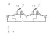
- FIG. 1 is a top view of a housing of an input device according to an embodiment;
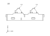
- FIG. 1 is a side view of a housing of an input device according to an embodiment;
- FIG. 1 is a bottom view of a housing of an input device according to an embodiment;
- FIG. 11 is a cross-sectional view illustrating the position of a shaft portion according to one embodiment.
- FIG. 1 is a perspective view showing an example of suitable dimensions of an input device according to an embodiment
- FIG. 13 is a top perspective view of a first modified example of a knob included in an input device according to an embodiment
- FIG. 1 is a top view of a first modified example of a knob included in an input device according to an embodiment
- FIG. 13 is a bottom view of a first modified example of a knob included in the input device according to the embodiment
- FIG. 11 is a cross-sectional view illustrating a second rib of a first modified example of a knob according to an embodiment.
- FIG. 11 is a cross-sectional view illustrating a through hole of a second modified example of a knob according to an embodiment of the present invention.
- FIG. 13 is a top perspective view of a first modified example of a knob included in an input device according to an embodiment
- FIG. 1 is a top view of a first modified example of a knob included in an input device according to an embodiment
- FIG. 13 is a bottom view of
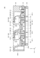
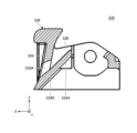
- the knob 130 is positioned very close to the panel top portion 121, but since the first inclined portion 134A and the second inclined portion 134B, which will be described in detail later, are formed at the upper end portion of the base portion 134 of the knob 130, the swinging knob 130 does not interfere with the panel top portion 121. This makes it easy to increase the distance in the vertical direction (Z-axis direction) from the position where the knob 130 and the actuator 150 that shifts in the vertical direction abut to the push switch 142 without increasing the distance from the panel upper surface portion 121 to the front of the upper surface 140A.
- the direction of the moment generated when the operating force is transmitted from the second pressing portion 133B to the tip portion 151 of the actuator 150-2 can be reduced to the vertical direction (Z-axis direction). This makes it easy to design the operating feel and the operating load because the operating force is efficiently transmitted from the knob 130 to the actuator 150-2. This also makes it possible to reduce the possibility that the force lost when the operating force is transmitted will damage the knob 130.
- the housing 110 has a pair of guide parts 112 arranged side by side in the front and rear for each of the two knobs 130 and the two knobs 230.
- the housing 110 has a total of eight guide parts 112.
- Each guide part 112 has a cylindrical shape that extends in the vertical direction.
- the panel member 120 is a resin box-shaped member having a hollow structure.
- the housing 110 and the base 134 of the knob 130 are disposed inside the hollow structure.
- the panel member 120 has a substantially rectangular parallelepiped shape.
- the housing 110, two knobs 130, and two knobs 230 are housed inside the panel member 120. That is, the panel member 120 is provided above the housing 110 and covers the housing 110.
- the panel member 120 is, for example, a member that constitutes a console for the driver's seat of a vehicle.
- the panel member 120 and the housing 110 are directly in contact with each other and fixed by a snap-in connection, but the panel member 120 and the housing 110 may be indirectly fixed via another member.
- the panel member 120 has a panel top surface 121 that is flat and parallel to the XY plane.
- a rectangular opening 122 is formed in the panel top surface 121 of the panel member 120, with the longitudinal direction being the left-right direction (Y-axis direction) when viewed in a plan view from above (positive Z-axis direction).
- the panel top surface 121 has two openings 122 formed side-by-side, one in front of the other.
- the openings 122 are holes into which the operator inserts his or her finger when pulling the operating portion 136 of the knob 130 to operate it.
- the operating portion 136 of the knob 130 is exposed and positioned at the rear of the opening 122, and receives the operating force from the operator.
- the panel member 120 has a part (front end 122A) of the panel upper surface portion 121 that constitutes the front (X-axis positive direction) side of the opening 122, a bottom wall portion 123 that is provided below the opening 122 and approximately parallel to the XY plane, and a connection portion 123A that extends downward from the front end portion 122A and connects the front end portion 122A and the bottom wall portion 123.
- the bottom wall portion 123 and the connection portion 123A have a curved shape and cover the front side (X-axis positive side) and lower side (Z-axis negative side) of the space 120A below the openings 122 in the panel member 120.
- Each of the two knobs 130 and the two knobs 230 is a resin member that swings in response to an operating force from an operator.
- Each of the two knobs 130 and the two knobs 230 has an approximately rectangular parallelepiped shape and has a hollow structure.
- the support part 111 of the housing 110 is inserted into the hollow structure from the lower side.
- Each of the two knobs 130 and the two knobs 230 is disposed above the housing 110 and connected to the corresponding support part 111 of the housing 110, thereby being supported so as to be swingable relative to the housing 110.
- Each knob 130 has a bearing hole 131 on each of the left and right side surfaces.
- Each knob 130 is supported so as to be rotatable relative to the housing 110 with the pair of left and right shaft parts 111B as a virtual swing center axis by fitting each of the pair of left and right bearing holes 131 into each of the pair of left and right shaft parts 111B provided on the support part 111.
- the range of the rotation stroke of each knob 130 is determined by the mechanical stopper 124 (described later in detail) and the lower end of the stroke of the push switch 142-1.
- the knob 130 rotates, the operating portion 136 swings upward (Z-axis positive direction) and downward (Z-axis negative direction).
- Each knob 130 has two ribs 134C (see FIGS. 8 and 9) parallel to the XZ plane.
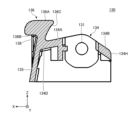
- Each knob 130 also has a front wall portion 135 formed continuously with the end portion 134D (an example of "one end") on the front side of the base portion 134. As shown in FIG. 2, the front wall portion 135 closes the X-axis positive side of the knob 130.
- the front wall 135 has a plate shape that is approximately parallel to the YZ plane, but the front wall 135 does not necessarily have to have a planar shape.
- the front wall 135 may, for example, include a curved shape in part, may have an undulating shape, or may include a wavy shape in part. As shown in FIG. 1 and FIG. 7, the front wall 135 extends from an end 134D on the front (X-axis positive direction) side of the base 134 toward the rear side of the opening 122.
- the upper end of the front wall 135 has an operation unit 136 that extends parallel to the XY plane and accepts operations by an operator. It is preferable that the operation unit 136 extends in a direction that intersects with the front wall 135 and in a direction parallel to the virtual swing center axis, and the operation unit 136 does not need to extend parallel to the XY plane.
- the operation unit 136 When the operation unit 136 is extended parallel to the XY plane, the operation unit 136 is easily visible from above even when the dimensions are set small.
- the operation unit 136 In the neutral state, the operation unit 136 is disposed along the end of the rear side of the opening 122.
- the front wall portion 135 is extended from the end portion 134D of the knob 130 toward substantially the upper side.
- the panel member 120 has an opposing portion 121A (an example of a "first opposing surface portion") that is provided in a portion on the X-axis negative side of the inner wall 121B that constitutes the opening 122, facing the operation unit 136 of the knob 130 and formed in a direction that diagonally intersects with the panel upper surface portion 121.
- the operation unit 136 that is parallel to the panel upper surface portion 121 is formed at the upper end of the front wall portion 135 of the knob 130, and the operation unit 136 is disposed on the rear side of the opening 122.
- the operation unit 136 is disposed opposite the facing portion 121A of the panel upper surface portion 121 constituting the rear side of the opening 122, and is disposed in front of the facing portion 121A (X-axis positive direction).
- the operating unit 136 has a facing portion 136C (an example of a "second facing surface portion”) disposed opposite the facing portion 121A on the X-axis negative side.
- the cover 140 is fixed to the housing 110 with the upper surface 140A parallel to the XY plane by engaging the multiple engagement claws 141 with each of the multiple openings 114 formed on the side of the housing 110.
- the cover 140 is described as a single member, but the cover 140 may be a combination of a substrate and a resin member.
- the input device 100 has a front (X-axis positive side) actuator 150-1 and a rear (X-axis negative side) actuator 150-2 for each of the four push switches 142.
- the tip 151 of actuator 150-1 abuts against the first pressing portion 133A of knob 130, and the bottom surface 152 abuts against the top surface of push switch 142-1.
- the tip 151 of actuator 150-2 abuts against the second pressing portion 133B of knob 130, and the bottom surface 152 abuts against the top surface of push switch 142-2.
- the knob 130 swings upward toward the front, and the second pressing portion 133B of the knob 130 presses the push switch 142-2 via the actuator 150-2. This switches the push switch 142-2 to the on state and outputs a detection signal.
- the knob 130 swings downward and the first pressing portion 133A of the knob 130 presses the push switch 142-1 via the actuator 150-1. This switches the push switch 142-1 to the on state and outputs a detection signal.
- the knob 130 uses the biasing force from the push switch 142-1 or the push switch 142-2 to return to the neutral state and maintain the neutral state.
- the knob 130 has a virtual pivot axis that is pivotally supported by the support portion 111 of the housing 110, and has a base portion 134 that is covered by the panel top surface portion 121.
- the knob 130 also has a front wall 135 and an operating part 136.
- the front wall 135 has a plate shape parallel to the axial direction of the imaginary swing center axis, and at least a portion of it extends from one end of the base 134 closer to the opening 122 toward the opening 122.
- the operating part 136 is provided at the end of the front wall 135 on the opening 122 side, and receives an operating force from the operator.
- the operation portion 136 of the knob 130 has a pressing operation surface portion 136A, a pulling operation surface portion 136B, and a first rib 137.
- the pressing operation surface portion 136A has a planar shape. In a neutral state in which the operating force applied to the operation portion 136 is released, the pressing operation surface portion 136A is provided on the same plane as the panel upper surface portion 121.
- the pulling operation surface portion 136B is formed on the rear side of the pressing operation surface portion 136A in the operation portion 136, and intersects with the front wall portion 135 to form a concave portion. In other words, the pulling operation surface portion 136B is an interior angle formed by the intersection of the operation portion 136 and the front wall portion 135 when viewed from the Y-axis direction.
- the pulling operation surface portion 136B forms a concave portion on the rear side of the pressing operation surface portion 136A and on the side farther from the virtual swing central axis (through hole 131A).
- the first rib 137 is provided in the concave portion, and extends in a plane direction perpendicular to the axial direction of the virtual swing central axis, connecting the front wall portion 135 and the pulling operation surface portion 136B.
- the first rib 137 is provided in a pair on one edge portion and the other edge portion of the front wall portion 135 in the axial direction of the virtual swing central axis. In other words, the first rib 137 is provided in a pair on the front wall portion 135, spaced apart in the direction of the virtual swing central axis.
- the operator's finger when an operator uses his/her finger to pull up the operation unit 136, the operator's finger can be securely hooked onto the pulling operation surface unit 136B, thereby enabling the operation to be performed reliably.
- the operation unit 136 has a generally quarter-circular shape when viewed from the left-right direction (Y-axis direction), and the pull operation surface portion 136B, which is the lower surface of the operation unit 136, is a horizontal surface.
- the input device 100 can prevent the operator's finger from slipping off the pull operation surface portion 136B when the operator uses his/her finger to pull up the operation unit 136, thereby enabling the operation to be performed more reliably.
- the pressing operation surface 136A of the operation unit 136 has a planar shape parallel to the XY plane, and is on the same plane as the panel top surface 121 of the panel member 120.
- the input device 100 can prevent the operation unit 136 from protruding beyond the panel top surface 121, making it difficult for objects to get caught on the operation unit 136, thereby preventing accidental lifting of the operation unit 136.
- the pressing operation surface portion 136A of the knob 130 in the neutral state is positioned at a position 0.1 mm higher in the up-down direction than the panel top surface portion 121 when the pressing operation surface portion 136A is pressed downward to shift by 1.4 mm, and when the pressing operation surface portion 136A is pressed downward by 1.5 mm or more (an example of "above a predetermined amount"), the push switch 142-1 generates a signal.
- the amount of pressure applied by knob 130 to push switch 142-1 is less than 1.5 mm, which is the predetermined amount for generating a signal, so push switch 142-1 does not generate a signal. If the height position of press operation surface 136A is originally set to a position lower than the height position of panel top surface 121, press operation surface 136A is not pressed and does not shift even if the operator places his/her elbow on panel top surface 121, so push switch 142-1 does not generate a signal.
- the panel top surface 121 covers the top of the base 134 of the knob 130, so when the operator does something like resting their elbow on the panel top surface 121, there is no possibility that the knob 130 will accidentally rotate in the opposite direction to that described above, and there is no risk of the rear push switch 142-2 being pressed.
- the base 134 of the knob 130 When viewed in the axial direction (i.e., Y-axis direction) of the imaginary swing central axis of the knob 130, the base 134 of the knob 130 has a mountain shape with a first inclined surface portion 134A that is provided in front (X-axis positive side) of the imaginary swing central axis (i.e., bearing hole 131) and inclined downward to the front, and a second inclined surface portion 134B that is provided behind (X-axis negative side) the imaginary swing central axis (i.e., bearing hole 131) and inclined downward to the rear.
- the base 134 when viewed in the axial direction (Y-axis direction) of the imaginary swing central axis of the knob 130, the base 134 has a first inclined surface portion 134A that is provided closer to the panel top surface portion 121 and closer to the opening 122 than the imaginary swing central axis of the knob 130 and inclined in a direction in which the distance from the panel top surface portion 121 increases as the distance from the opening 122 becomes closer to the panel top surface portion 121.
- the base 134 when viewed from the axial direction (Y-axis direction) of the imaginary pivot axis of the knob 130, the base 134 has a second inclined surface 134B that is provided on the side of the panel upper surface 121 opposite the first inclined surface 134A with respect to the imaginary pivot axis of the knob 130, and is inclined in a direction in which the distance from the panel upper surface 121 increases as the distance from the opening 122 increases with respect to the panel upper surface 121.
- the first inclined surface 134A has a flat shape, but the first inclined surface 134A may have a curved shape as long as the tendency of the inclination with respect to the panel upper surface 121 is the same as above. The same is true for the second inclined surface 134B.
- the input device 100 can bring the virtual swing center axis of the knob 130 (i.e., the bearing hole 131) closer to the panel top surface 121 (i.e., the height position of the virtual swing center axis of the knob 130 can be increased), and since the base 134 has the mountain shape, the base 134 can be prevented from interfering with the panel top surface 121 when the knob 130 swings.
- the panel upper surface portion 121 of the panel member 120 has a protruding mechanical stopper 124 provided on the lower surface of the panel upper surface portion 121 (the surface facing the first inclined surface portion 134A of the knob 130) and on the rear side of the opening 122 (negative side of the X-axis) so as to protrude toward the first inclined surface portion 134A.
- the mechanical stopper 124 faces the first inclined surface portion 134A of the base portion 134 of the knob 130 at a predetermined distance, and abuts against the front end portion (positive end portion of the X-axis) of the first inclined surface portion 134A when the knob 130 swings upward by a predetermined amount.
- the input device 100 can restrict the amount of upward swing of the knob 130 to a predetermined amount. Furthermore, the input device 100 according to one embodiment can abut the mechanical stopper 124 against the front end of the first inclined surface portion 134A of the base 134 (i.e., near the operating portion 136), thereby efficiently transmitting the restraining force of the mechanical stopper 124 to the operator's finger, and can prevent the entire knob 130 from bending, thereby preventing damage to the knob 130.
- the knob 130 has a pair of first ribs 137 provided at a corner 138 formed by the front wall 135 and the operating part 136, at both ends in the axial direction (Y-axis direction) of the imaginary central axis of the swing of the knob 130.
- the first rib 137 has a vertical, approximately triangular plate shape, with an upper edge connected to the operating part 136 and a rear edge connected to the front wall 135.
- the interior angle formed by the intersection of the operation unit 136 on the back side (negative Z-axis side) of the operation unit 136 and the side farther from the virtual swing center axis of the knob 130 (positive X-axis side) and the front wall portion 135 is an acute angle.
- the shape formed by the front wall portion 135 and the operating portion 136 resembles the Arabic numeral "7.”
- the width L2 When the width L2 is set to 10 mm or less, it is difficult to set the operation load when performing a pressing operation and the operation load when performing a pulling operation to the same magnitude, and therefore the balance of the operation feel is poor.
- the width L2 When the width L2 is set to 14 mm or more, the input device becomes large.
- the base 134 has a first slope portion 134A and a second slope portion 134B, making it easy to set the width L2 to a suitable value.
- the dimension (width L3) of the opening 122 in the front-rear direction (X-axis direction) minus the width L1 is 22 mm. That is, the ratio of the dimension L3 of the opening 122 minus the width L1 to the dimension L1 of the operation unit 136 is 22:6. From the viewpoint of market needs for miniaturization, it is preferable that the width L3 is set as small as possible while maintaining a size that allows an adult male to insert his fingertip into the opening 122.
- the shape from the front end 122A to the connection unit 123A has a curved shape with a predetermined curvature radius so that the operator can easily find the position to operate by relying on the touch when operating by blind touch without looking at the input device 100. If a curved shape is formed from the front end 122A to the connection unit 123A, it becomes easier for the operator to find the operation unit 136 by relying on the touch. If no curved surface is formed from front end 122A to connection 123A, the minimum dimension required for width L3 is 11 mm. Width L3 is set large depending on the radius of curvature of the curved surface provided at connection 123A.
- Fig. 17 is a top perspective view of a first modified example of the knob 130 included in the input device according to one embodiment.
- Fig. 18 is a top view of the first modified example of the knob 130 included in the input device according to one embodiment.
- Fig. 19 is a bottom view of the first modified example of the knob 130 included in the input device according to one embodiment.
- Fig. 20 is a cross-sectional view illustrating a second rib 238 of the first modified example of the knob 130 according to one embodiment.
- the knob 230 shown in Figures 17 to 20 is a first modified example of the knob 130 according to one embodiment.
- the knob 230 has a second rib 238 extending parallel to the XZ plane from the front wall portion 235 toward the negative X-axis direction.
- the upper end face (positive Z-axis side) of the second rib 238 is a first inclined surface portion 234A.
- the first inclined surface portion 234A is provided on the positive X-axis side of the imaginary swing center axis (i.e., the bearing hole 231) of the base 234 of the knob 230.
- knob 230 This allows the knob 230 to reinforce the front wall portion 235 and the base portion 234, and suppresses deformation of the front wall portion 235 when the operating portion 236 receives an operation.
- the knob 230 has a configuration that is superior in productivity to other embodiments of the present application.
- the directions (W1 direction, W2 direction) parallel to the XZ plane shown in FIG. 20 are the directions in which the mold is removed when the knob 230 is manufactured using a resin molding method. All shapes constituting the knob 230 except the bearing hole 231 do not collide with the direction in which the mold is removed (W1 direction, W2 direction). In order to reduce the work force required to remove the mold, it is preferable that all shapes constituting the knob 230 except the bearing hole 231 are set to a shape that intersects obliquely with the direction in which the mold is removed (W1 direction, W2 direction shown in FIG. 20).
- the interior angle formed by the intersection of the operating part 236 and the front wall part 235 is set to an acute angle.
- the interior angle formed by the intersection of the front wall part 235 and the first inclined surface part 234A is set to an acute angle.
- the operating portion 236, the front wall portion 235, and the first slope portion 234A have a shape similar to the letter "Z.”
- FIG. 23 is an external perspective view of an input device 500 including a fourth modified knob 130 according to an embodiment.
- FIG. 24 is a perspective view of the fourth modified knob 130 according to an embodiment.
- the input device 500 includes a knob 530 (an example of a "knob") without a light guide hole. Therefore, the input device 500 does not have an illumination display function.
- the knob 530 of the input device 500 does not have a through hole for light guide in the base 534, and the first inclined surface portion 534A and the second inclined surface portion 534B are continuous, so that the base 534 is structurally stronger than the bases in other embodiments.
Landscapes
- Switches With Compound Operations (AREA)
- Tumbler Switches (AREA)
Abstract
Dans la présente invention : un élément panneau comporte une partie surface supérieure de panneau et des ouvertures; une protubérance comporte une partie de base, une partie paroi avant et une partie d'actionnement; la partie d'actionnement comporte une partie surface d'actionnement de pression qui doit être pressée par un opérateur; lorsqu'elle est vue depuis une direction d'axe central de pivot virtuel, dans un état neutre dans lequel il n'y a pas de force d'actionnement, la position relative de la partie surface d'actionnement de pression dans la direction verticale par rapport à la partie surface supérieure de panneau se trouve au-dessus de la partie surface supérieure de panneau; lorsque la partie surface d'actionnement de pression est pressée par une force d'actionnement à partir de l'état neutre, et que la partie surface d'actionnement de pression se déplace vers le même plan que la partie surface supérieure de panneau, la quantité de pression au niveau d'un point de contact par la protubérance devient inférieure à une quantité prescrite, et le point de contact est disposé à une position où aucun signal n'est généré; et, lorsque la partie surface d'actionnement de pression est à nouveau pressée à la suite d'une force de pression et se déplace sous la partie surface supérieure de panneau, la quantité de pression au niveau du point de contact par la protubérance devient supérieure à la quantité prescrite, et le point de contact est disposé à une position où un signal est généré.
Applications Claiming Priority (2)
| Application Number | Priority Date | Filing Date | Title |
|---|---|---|---|
| JP2024-000829 | 2024-01-05 | ||
| JP2024000829A JP2025107076A (ja) | 2024-01-05 | 2024-01-05 | 入力装置 |
Publications (1)
| Publication Number | Publication Date |
|---|---|
| WO2025146830A1 true WO2025146830A1 (fr) | 2025-07-10 |
Family
ID=96300444
Family Applications (1)
| Application Number | Title | Priority Date | Filing Date |
|---|---|---|---|
| PCT/JP2025/007545 Pending WO2025146830A1 (fr) | 2024-01-05 | 2025-03-03 | Dispositif d'entrée |
Country Status (2)
| Country | Link |
|---|---|
| JP (1) | JP2025107076A (fr) |
| WO (1) | WO2025146830A1 (fr) |
Citations (3)
| Publication number | Priority date | Publication date | Assignee | Title |
|---|---|---|---|---|
| JPS6292737U (fr) * | 1985-11-29 | 1987-06-13 | ||
| JP2006221929A (ja) * | 2005-02-09 | 2006-08-24 | Omron Corp | スイッチ装置 |
| JP2013243035A (ja) * | 2012-05-21 | 2013-12-05 | Tokai Rika Co Ltd | スイッチ装置 |
-
2024
- 2024-01-05 JP JP2024000829A patent/JP2025107076A/ja active Pending
-
2025
- 2025-03-03 WO PCT/JP2025/007545 patent/WO2025146830A1/fr active Pending
Patent Citations (3)
| Publication number | Priority date | Publication date | Assignee | Title |
|---|---|---|---|---|
| JPS6292737U (fr) * | 1985-11-29 | 1987-06-13 | ||
| JP2006221929A (ja) * | 2005-02-09 | 2006-08-24 | Omron Corp | スイッチ装置 |
| JP2013243035A (ja) * | 2012-05-21 | 2013-12-05 | Tokai Rika Co Ltd | スイッチ装置 |
Also Published As
| Publication number | Publication date |
|---|---|
| JP2025107076A (ja) | 2025-07-17 |
Similar Documents
| Publication | Publication Date | Title |
|---|---|---|
| JP3758129B2 (ja) | スイッチ装置 | |
| JP5555015B2 (ja) | 車載用入力装置 | |
| US20030038020A1 (en) | Switch | |
| JP4682618B2 (ja) | 押しボタンスイッチ | |
| US20250065227A1 (en) | Input device | |
| US20250065225A1 (en) | Input device | |
| JP5859884B2 (ja) | ステアリングスイッチ装置 | |
| WO2025146830A1 (fr) | Dispositif d'entrée | |
| US20250050203A1 (en) | Input device and top member of operation stick | |
| US5225970A (en) | Twist-in mounting for electromechanical component | |
| JP4464846B2 (ja) | スイッチ装置 | |
| JP4395035B2 (ja) | 揺動操作型電気部品 | |
| JP7758756B2 (ja) | 入力デバイス | |
| JP7601314B2 (ja) | 入力装置 | |
| JP2007042431A (ja) | 操作ボタンの取り付け構造及びこれを備えた画像形成装置 | |
| JP7732336B2 (ja) | 車両用ドアハンドル装置 | |
| JP7648033B2 (ja) | スイッチ装置 | |
| JP4713425B2 (ja) | ステアリングスイッチ装置 | |
| US11915893B2 (en) | Multi-directional operation switch device | |
| US20240267048A1 (en) | Input Device | |
| US20250060792A1 (en) | Input device and cover of input device | |
| US20250060794A1 (en) | Input device and exterior cover of input device | |
| US20250060837A1 (en) | Input device and operation stick unit | |
| JP4463500B2 (ja) | 操作スイッチユニット | |
| JP7491044B2 (ja) | 押釦構造および電子機器 |
Legal Events
| Date | Code | Title | Description |
|---|---|---|---|
| 121 | Ep: the epo has been informed by wipo that ep was designated in this application |
Ref document number: 25736483 Country of ref document: EP Kind code of ref document: A1 |