WO2025146830A1 - 入力装置 - Google Patents
入力装置 Download PDFInfo
- Publication number
- WO2025146830A1 WO2025146830A1 PCT/JP2025/007545 JP2025007545W WO2025146830A1 WO 2025146830 A1 WO2025146830 A1 WO 2025146830A1 JP 2025007545 W JP2025007545 W JP 2025007545W WO 2025146830 A1 WO2025146830 A1 WO 2025146830A1
- Authority
- WO
- WIPO (PCT)
- Prior art keywords
- knob
- surface portion
- central axis
- input device
- panel
- Prior art date
- Legal status (The legal status is an assumption and is not a legal conclusion. Google has not performed a legal analysis and makes no representation as to the accuracy of the status listed.)
- Pending
Links
Images









Classifications
-
- H—ELECTRICITY
- H01—ELECTRIC ELEMENTS
- H01H—ELECTRIC SWITCHES; RELAYS; SELECTORS; EMERGENCY PROTECTIVE DEVICES
- H01H23/00—Tumbler or rocker switches, i.e. switches characterised by being operated by rocking an operating member in the form of a rocker button
- H01H23/02—Details
- H01H23/12—Movable parts; Contacts mounted thereon
- H01H23/14—Tumblers
-
- H—ELECTRICITY
- H01—ELECTRIC ELEMENTS
- H01H—ELECTRIC SWITCHES; RELAYS; SELECTORS; EMERGENCY PROTECTIVE DEVICES
- H01H23/00—Tumbler or rocker switches, i.e. switches characterised by being operated by rocking an operating member in the form of a rocker button
- H01H23/28—Tumbler or rocker switches, i.e. switches characterised by being operated by rocking an operating member in the form of a rocker button with three operating positions
- H01H23/30—Tumbler or rocker switches, i.e. switches characterised by being operated by rocking an operating member in the form of a rocker button with three operating positions with stable centre positions and one or both end positions unstable
Definitions
- the present invention relates to an input device.
- Patent Documents 1 and 2 disclose an in-vehicle switch device that includes a switch, a swinging knob, and a panel member, and in which the switch is pressed when the knob swings due to the operating force from the user, and the signal generated thereby drives an electric mechanism.
- the entire top surface of the knob is exposed to the operating surface.
- the operating portion of the knob protrudes above the panel member.
- the input device can reduce the possibility of erroneous operation and increase the safety of vehicle occupants.
- FIG. 2 is an external perspective view of a knob included in an input device according to an embodiment, as viewed obliquely from above;
- FIG. 1 is an external perspective view of a knob included in an input device according to an embodiment, viewed from diagonally below;
- FIG. 1 is a top view of a knob included in an input device according to an embodiment;
- FIG. 1 is a bottom view of a knob included in an input device according to an embodiment;
- FIG. 1 is a top view of a housing of an input device according to an embodiment;
- FIG. 1 is a side view of a housing of an input device according to an embodiment;
- FIG. 1 is a bottom view of a housing of an input device according to an embodiment;
- FIG. 11 is a cross-sectional view illustrating the position of a shaft portion according to one embodiment.
- FIG. 1 is a perspective view showing an example of suitable dimensions of an input device according to an embodiment
- FIG. 13 is a top perspective view of a first modified example of a knob included in an input device according to an embodiment
- FIG. 1 is a top view of a first modified example of a knob included in an input device according to an embodiment
- FIG. 13 is a bottom view of a first modified example of a knob included in the input device according to the embodiment
- FIG. 11 is a cross-sectional view illustrating a second rib of a first modified example of a knob according to an embodiment.
- FIG. 11 is a cross-sectional view illustrating a through hole of a second modified example of a knob according to an embodiment of the present invention.
- FIG. 13 is a top perspective view of a first modified example of a knob included in an input device according to an embodiment
- FIG. 1 is a top view of a first modified example of a knob included in an input device according to an embodiment
- FIG. 13 is a bottom view of
- the knob 130 is positioned very close to the panel top portion 121, but since the first inclined portion 134A and the second inclined portion 134B, which will be described in detail later, are formed at the upper end portion of the base portion 134 of the knob 130, the swinging knob 130 does not interfere with the panel top portion 121. This makes it easy to increase the distance in the vertical direction (Z-axis direction) from the position where the knob 130 and the actuator 150 that shifts in the vertical direction abut to the push switch 142 without increasing the distance from the panel upper surface portion 121 to the front of the upper surface 140A.
- the direction of the moment generated when the operating force is transmitted from the second pressing portion 133B to the tip portion 151 of the actuator 150-2 can be reduced to the vertical direction (Z-axis direction). This makes it easy to design the operating feel and the operating load because the operating force is efficiently transmitted from the knob 130 to the actuator 150-2. This also makes it possible to reduce the possibility that the force lost when the operating force is transmitted will damage the knob 130.
- the housing 110 has a pair of guide parts 112 arranged side by side in the front and rear for each of the two knobs 130 and the two knobs 230.
- the housing 110 has a total of eight guide parts 112.
- Each guide part 112 has a cylindrical shape that extends in the vertical direction.
- the panel member 120 is a resin box-shaped member having a hollow structure.
- the housing 110 and the base 134 of the knob 130 are disposed inside the hollow structure.
- the panel member 120 has a substantially rectangular parallelepiped shape.
- the housing 110, two knobs 130, and two knobs 230 are housed inside the panel member 120. That is, the panel member 120 is provided above the housing 110 and covers the housing 110.
- the panel member 120 is, for example, a member that constitutes a console for the driver's seat of a vehicle.
- the panel member 120 and the housing 110 are directly in contact with each other and fixed by a snap-in connection, but the panel member 120 and the housing 110 may be indirectly fixed via another member.
- the panel member 120 has a panel top surface 121 that is flat and parallel to the XY plane.
- a rectangular opening 122 is formed in the panel top surface 121 of the panel member 120, with the longitudinal direction being the left-right direction (Y-axis direction) when viewed in a plan view from above (positive Z-axis direction).
- the panel top surface 121 has two openings 122 formed side-by-side, one in front of the other.
- the openings 122 are holes into which the operator inserts his or her finger when pulling the operating portion 136 of the knob 130 to operate it.
- the operating portion 136 of the knob 130 is exposed and positioned at the rear of the opening 122, and receives the operating force from the operator.
- the panel member 120 has a part (front end 122A) of the panel upper surface portion 121 that constitutes the front (X-axis positive direction) side of the opening 122, a bottom wall portion 123 that is provided below the opening 122 and approximately parallel to the XY plane, and a connection portion 123A that extends downward from the front end portion 122A and connects the front end portion 122A and the bottom wall portion 123.
- the bottom wall portion 123 and the connection portion 123A have a curved shape and cover the front side (X-axis positive side) and lower side (Z-axis negative side) of the space 120A below the openings 122 in the panel member 120.
- Each of the two knobs 130 and the two knobs 230 is a resin member that swings in response to an operating force from an operator.
- Each of the two knobs 130 and the two knobs 230 has an approximately rectangular parallelepiped shape and has a hollow structure.
- the support part 111 of the housing 110 is inserted into the hollow structure from the lower side.
- Each of the two knobs 130 and the two knobs 230 is disposed above the housing 110 and connected to the corresponding support part 111 of the housing 110, thereby being supported so as to be swingable relative to the housing 110.
- Each knob 130 has a bearing hole 131 on each of the left and right side surfaces.
- Each knob 130 is supported so as to be rotatable relative to the housing 110 with the pair of left and right shaft parts 111B as a virtual swing center axis by fitting each of the pair of left and right bearing holes 131 into each of the pair of left and right shaft parts 111B provided on the support part 111.
- the range of the rotation stroke of each knob 130 is determined by the mechanical stopper 124 (described later in detail) and the lower end of the stroke of the push switch 142-1.
- the knob 130 rotates, the operating portion 136 swings upward (Z-axis positive direction) and downward (Z-axis negative direction).
- Each knob 130 has two ribs 134C (see FIGS. 8 and 9) parallel to the XZ plane.
- Each knob 130 also has a front wall portion 135 formed continuously with the end portion 134D (an example of "one end") on the front side of the base portion 134. As shown in FIG. 2, the front wall portion 135 closes the X-axis positive side of the knob 130.
- the front wall 135 has a plate shape that is approximately parallel to the YZ plane, but the front wall 135 does not necessarily have to have a planar shape.
- the front wall 135 may, for example, include a curved shape in part, may have an undulating shape, or may include a wavy shape in part. As shown in FIG. 1 and FIG. 7, the front wall 135 extends from an end 134D on the front (X-axis positive direction) side of the base 134 toward the rear side of the opening 122.
- the upper end of the front wall 135 has an operation unit 136 that extends parallel to the XY plane and accepts operations by an operator. It is preferable that the operation unit 136 extends in a direction that intersects with the front wall 135 and in a direction parallel to the virtual swing center axis, and the operation unit 136 does not need to extend parallel to the XY plane.
- the operation unit 136 When the operation unit 136 is extended parallel to the XY plane, the operation unit 136 is easily visible from above even when the dimensions are set small.
- the operation unit 136 In the neutral state, the operation unit 136 is disposed along the end of the rear side of the opening 122.
- the front wall portion 135 is extended from the end portion 134D of the knob 130 toward substantially the upper side.
- the panel member 120 has an opposing portion 121A (an example of a "first opposing surface portion") that is provided in a portion on the X-axis negative side of the inner wall 121B that constitutes the opening 122, facing the operation unit 136 of the knob 130 and formed in a direction that diagonally intersects with the panel upper surface portion 121.
- the operation unit 136 that is parallel to the panel upper surface portion 121 is formed at the upper end of the front wall portion 135 of the knob 130, and the operation unit 136 is disposed on the rear side of the opening 122.
- the operation unit 136 is disposed opposite the facing portion 121A of the panel upper surface portion 121 constituting the rear side of the opening 122, and is disposed in front of the facing portion 121A (X-axis positive direction).
- the operating unit 136 has a facing portion 136C (an example of a "second facing surface portion”) disposed opposite the facing portion 121A on the X-axis negative side.
- the cover 140 is fixed to the housing 110 with the upper surface 140A parallel to the XY plane by engaging the multiple engagement claws 141 with each of the multiple openings 114 formed on the side of the housing 110.
- the cover 140 is described as a single member, but the cover 140 may be a combination of a substrate and a resin member.
- the input device 100 has a front (X-axis positive side) actuator 150-1 and a rear (X-axis negative side) actuator 150-2 for each of the four push switches 142.
- the tip 151 of actuator 150-1 abuts against the first pressing portion 133A of knob 130, and the bottom surface 152 abuts against the top surface of push switch 142-1.
- the tip 151 of actuator 150-2 abuts against the second pressing portion 133B of knob 130, and the bottom surface 152 abuts against the top surface of push switch 142-2.
- the knob 130 swings upward toward the front, and the second pressing portion 133B of the knob 130 presses the push switch 142-2 via the actuator 150-2. This switches the push switch 142-2 to the on state and outputs a detection signal.
- the knob 130 swings downward and the first pressing portion 133A of the knob 130 presses the push switch 142-1 via the actuator 150-1. This switches the push switch 142-1 to the on state and outputs a detection signal.
- the knob 130 uses the biasing force from the push switch 142-1 or the push switch 142-2 to return to the neutral state and maintain the neutral state.
- the knob 130 has a virtual pivot axis that is pivotally supported by the support portion 111 of the housing 110, and has a base portion 134 that is covered by the panel top surface portion 121.
- the knob 130 also has a front wall 135 and an operating part 136.
- the front wall 135 has a plate shape parallel to the axial direction of the imaginary swing center axis, and at least a portion of it extends from one end of the base 134 closer to the opening 122 toward the opening 122.
- the operating part 136 is provided at the end of the front wall 135 on the opening 122 side, and receives an operating force from the operator.
- the operation portion 136 of the knob 130 has a pressing operation surface portion 136A, a pulling operation surface portion 136B, and a first rib 137.
- the pressing operation surface portion 136A has a planar shape. In a neutral state in which the operating force applied to the operation portion 136 is released, the pressing operation surface portion 136A is provided on the same plane as the panel upper surface portion 121.
- the pulling operation surface portion 136B is formed on the rear side of the pressing operation surface portion 136A in the operation portion 136, and intersects with the front wall portion 135 to form a concave portion. In other words, the pulling operation surface portion 136B is an interior angle formed by the intersection of the operation portion 136 and the front wall portion 135 when viewed from the Y-axis direction.
- the pulling operation surface portion 136B forms a concave portion on the rear side of the pressing operation surface portion 136A and on the side farther from the virtual swing central axis (through hole 131A).
- the first rib 137 is provided in the concave portion, and extends in a plane direction perpendicular to the axial direction of the virtual swing central axis, connecting the front wall portion 135 and the pulling operation surface portion 136B.
- the first rib 137 is provided in a pair on one edge portion and the other edge portion of the front wall portion 135 in the axial direction of the virtual swing central axis. In other words, the first rib 137 is provided in a pair on the front wall portion 135, spaced apart in the direction of the virtual swing central axis.
- the operator's finger when an operator uses his/her finger to pull up the operation unit 136, the operator's finger can be securely hooked onto the pulling operation surface unit 136B, thereby enabling the operation to be performed reliably.
- the operation unit 136 has a generally quarter-circular shape when viewed from the left-right direction (Y-axis direction), and the pull operation surface portion 136B, which is the lower surface of the operation unit 136, is a horizontal surface.
- the input device 100 can prevent the operator's finger from slipping off the pull operation surface portion 136B when the operator uses his/her finger to pull up the operation unit 136, thereby enabling the operation to be performed more reliably.
- the pressing operation surface 136A of the operation unit 136 has a planar shape parallel to the XY plane, and is on the same plane as the panel top surface 121 of the panel member 120.
- the input device 100 can prevent the operation unit 136 from protruding beyond the panel top surface 121, making it difficult for objects to get caught on the operation unit 136, thereby preventing accidental lifting of the operation unit 136.
- the pressing operation surface portion 136A of the knob 130 in the neutral state is positioned at a position 0.1 mm higher in the up-down direction than the panel top surface portion 121 when the pressing operation surface portion 136A is pressed downward to shift by 1.4 mm, and when the pressing operation surface portion 136A is pressed downward by 1.5 mm or more (an example of "above a predetermined amount"), the push switch 142-1 generates a signal.
- the amount of pressure applied by knob 130 to push switch 142-1 is less than 1.5 mm, which is the predetermined amount for generating a signal, so push switch 142-1 does not generate a signal. If the height position of press operation surface 136A is originally set to a position lower than the height position of panel top surface 121, press operation surface 136A is not pressed and does not shift even if the operator places his/her elbow on panel top surface 121, so push switch 142-1 does not generate a signal.
- the panel top surface 121 covers the top of the base 134 of the knob 130, so when the operator does something like resting their elbow on the panel top surface 121, there is no possibility that the knob 130 will accidentally rotate in the opposite direction to that described above, and there is no risk of the rear push switch 142-2 being pressed.
- the base 134 of the knob 130 When viewed in the axial direction (i.e., Y-axis direction) of the imaginary swing central axis of the knob 130, the base 134 of the knob 130 has a mountain shape with a first inclined surface portion 134A that is provided in front (X-axis positive side) of the imaginary swing central axis (i.e., bearing hole 131) and inclined downward to the front, and a second inclined surface portion 134B that is provided behind (X-axis negative side) the imaginary swing central axis (i.e., bearing hole 131) and inclined downward to the rear.
- the base 134 when viewed in the axial direction (Y-axis direction) of the imaginary swing central axis of the knob 130, the base 134 has a first inclined surface portion 134A that is provided closer to the panel top surface portion 121 and closer to the opening 122 than the imaginary swing central axis of the knob 130 and inclined in a direction in which the distance from the panel top surface portion 121 increases as the distance from the opening 122 becomes closer to the panel top surface portion 121.
- the base 134 when viewed from the axial direction (Y-axis direction) of the imaginary pivot axis of the knob 130, the base 134 has a second inclined surface 134B that is provided on the side of the panel upper surface 121 opposite the first inclined surface 134A with respect to the imaginary pivot axis of the knob 130, and is inclined in a direction in which the distance from the panel upper surface 121 increases as the distance from the opening 122 increases with respect to the panel upper surface 121.
- the first inclined surface 134A has a flat shape, but the first inclined surface 134A may have a curved shape as long as the tendency of the inclination with respect to the panel upper surface 121 is the same as above. The same is true for the second inclined surface 134B.
- the input device 100 can bring the virtual swing center axis of the knob 130 (i.e., the bearing hole 131) closer to the panel top surface 121 (i.e., the height position of the virtual swing center axis of the knob 130 can be increased), and since the base 134 has the mountain shape, the base 134 can be prevented from interfering with the panel top surface 121 when the knob 130 swings.
- the panel upper surface portion 121 of the panel member 120 has a protruding mechanical stopper 124 provided on the lower surface of the panel upper surface portion 121 (the surface facing the first inclined surface portion 134A of the knob 130) and on the rear side of the opening 122 (negative side of the X-axis) so as to protrude toward the first inclined surface portion 134A.
- the mechanical stopper 124 faces the first inclined surface portion 134A of the base portion 134 of the knob 130 at a predetermined distance, and abuts against the front end portion (positive end portion of the X-axis) of the first inclined surface portion 134A when the knob 130 swings upward by a predetermined amount.
- the input device 100 can restrict the amount of upward swing of the knob 130 to a predetermined amount. Furthermore, the input device 100 according to one embodiment can abut the mechanical stopper 124 against the front end of the first inclined surface portion 134A of the base 134 (i.e., near the operating portion 136), thereby efficiently transmitting the restraining force of the mechanical stopper 124 to the operator's finger, and can prevent the entire knob 130 from bending, thereby preventing damage to the knob 130.
- the knob 130 has a pair of first ribs 137 provided at a corner 138 formed by the front wall 135 and the operating part 136, at both ends in the axial direction (Y-axis direction) of the imaginary central axis of the swing of the knob 130.
- the first rib 137 has a vertical, approximately triangular plate shape, with an upper edge connected to the operating part 136 and a rear edge connected to the front wall 135.
- the interior angle formed by the intersection of the operation unit 136 on the back side (negative Z-axis side) of the operation unit 136 and the side farther from the virtual swing center axis of the knob 130 (positive X-axis side) and the front wall portion 135 is an acute angle.
- the shape formed by the front wall portion 135 and the operating portion 136 resembles the Arabic numeral "7.”
- the width L2 When the width L2 is set to 10 mm or less, it is difficult to set the operation load when performing a pressing operation and the operation load when performing a pulling operation to the same magnitude, and therefore the balance of the operation feel is poor.
- the width L2 When the width L2 is set to 14 mm or more, the input device becomes large.
- the base 134 has a first slope portion 134A and a second slope portion 134B, making it easy to set the width L2 to a suitable value.
- the dimension (width L3) of the opening 122 in the front-rear direction (X-axis direction) minus the width L1 is 22 mm. That is, the ratio of the dimension L3 of the opening 122 minus the width L1 to the dimension L1 of the operation unit 136 is 22:6. From the viewpoint of market needs for miniaturization, it is preferable that the width L3 is set as small as possible while maintaining a size that allows an adult male to insert his fingertip into the opening 122.
- the shape from the front end 122A to the connection unit 123A has a curved shape with a predetermined curvature radius so that the operator can easily find the position to operate by relying on the touch when operating by blind touch without looking at the input device 100. If a curved shape is formed from the front end 122A to the connection unit 123A, it becomes easier for the operator to find the operation unit 136 by relying on the touch. If no curved surface is formed from front end 122A to connection 123A, the minimum dimension required for width L3 is 11 mm. Width L3 is set large depending on the radius of curvature of the curved surface provided at connection 123A.
- Fig. 17 is a top perspective view of a first modified example of the knob 130 included in the input device according to one embodiment.
- Fig. 18 is a top view of the first modified example of the knob 130 included in the input device according to one embodiment.
- Fig. 19 is a bottom view of the first modified example of the knob 130 included in the input device according to one embodiment.
- Fig. 20 is a cross-sectional view illustrating a second rib 238 of the first modified example of the knob 130 according to one embodiment.
- the knob 230 shown in Figures 17 to 20 is a first modified example of the knob 130 according to one embodiment.
- the knob 230 has a second rib 238 extending parallel to the XZ plane from the front wall portion 235 toward the negative X-axis direction.
- the upper end face (positive Z-axis side) of the second rib 238 is a first inclined surface portion 234A.
- the first inclined surface portion 234A is provided on the positive X-axis side of the imaginary swing center axis (i.e., the bearing hole 231) of the base 234 of the knob 230.
- knob 230 This allows the knob 230 to reinforce the front wall portion 235 and the base portion 234, and suppresses deformation of the front wall portion 235 when the operating portion 236 receives an operation.
- the knob 230 has a configuration that is superior in productivity to other embodiments of the present application.
- the directions (W1 direction, W2 direction) parallel to the XZ plane shown in FIG. 20 are the directions in which the mold is removed when the knob 230 is manufactured using a resin molding method. All shapes constituting the knob 230 except the bearing hole 231 do not collide with the direction in which the mold is removed (W1 direction, W2 direction). In order to reduce the work force required to remove the mold, it is preferable that all shapes constituting the knob 230 except the bearing hole 231 are set to a shape that intersects obliquely with the direction in which the mold is removed (W1 direction, W2 direction shown in FIG. 20).
- the interior angle formed by the intersection of the operating part 236 and the front wall part 235 is set to an acute angle.
- the interior angle formed by the intersection of the front wall part 235 and the first inclined surface part 234A is set to an acute angle.
- the operating portion 236, the front wall portion 235, and the first slope portion 234A have a shape similar to the letter "Z.”
- FIG. 23 is an external perspective view of an input device 500 including a fourth modified knob 130 according to an embodiment.
- FIG. 24 is a perspective view of the fourth modified knob 130 according to an embodiment.
- the input device 500 includes a knob 530 (an example of a "knob") without a light guide hole. Therefore, the input device 500 does not have an illumination display function.
- the knob 530 of the input device 500 does not have a through hole for light guide in the base 534, and the first inclined surface portion 534A and the second inclined surface portion 534B are continuous, so that the base 534 is structurally stronger than the bases in other embodiments.
Landscapes
- Switches With Compound Operations (AREA)
- Tumbler Switches (AREA)
Abstract
パネル部材は、パネル上面部と、開口部とを有し、ノブは、基部と、前壁部と、操作部とを有し、操作部は、操作者に押圧される押圧操作面部を有し、仮想揺動中心軸方向から視たとき、押圧操作面部のパネル上面部に対する上下方向の相対位置は、操作力から解放された中立状態ではパネル上面部より上方に位置し、中立状態から操作力によって押圧された押圧操作面部がパネル上面部と同一平面上になるまで遷移した時には、ノブによる接点の押圧量が所定の量より小さくなり、接点が信号を生成しない位置に設けられ、操作力によってさらに押圧された押圧操作面部がパネル上面部よりも下方に遷移した時には、ノブによる接点の押圧量が所定の量以上となり、接点が信号を生成する位置に設けられる。
Description
本発明は、入力装置に関する。
下記特許文献1および特許文献2には、スイッチと、揺動するノブと、パネル部材とを備え、ユーザからの操作力によってノブが揺動した時にスイッチが押圧され、それにより生成された信号が電動機構を駆動させる車載スイッチ装置が開示されている。
しかしながら、特許文献1に開示されている車載スイッチ装置は、ノブの上面の全てが操作面に対して露出していた。また、特許文献2に開示されている車載スイッチ装置は、ノブの操作部がパネル部材よりも上方まで飛び出していた。そのため、例えば子どもの悪戯などによって操作面に対して意図せぬ力が加えられた時、ノブが揺動してスイッチが信号を生成してしまうため、電動機構が駆動して車両の乗員の身が危険に晒されてしまう虞があった。
一実施形態に係る入力装置は、筐体と、筐体を覆うパネル部材と、操作者によって操作されるノブと、ノブによって所定の押圧量以上に押圧された際に、信号を生成する接点とを備え、パネル部材は、平面形状を有するパネル上面部と、パネル上面部に形成され、ノブの少なくとも一部を露出する開口部とを有し、ノブは、筐体によって支持される仮想揺動中心軸を有し、パネル上面部によって覆われて仮想揺動中心軸の周りを揺動する基部と、基部に設けられ、開口部の下方から開口部に向けて延在する前壁部と、前壁部の端部に設けられ、開口部から露出して操作者からの操作力を受け付ける操作部とを有し、操作部は、操作者に押圧される押圧操作面部を有し、仮想揺動中心軸方向から視たとき、押圧操作面部のパネル上面部に対する上下方向の相対位置は、操作力から解放された中立状態ではパネル上面部より上方に位置し、中立状態から操作力によって押圧された押圧操作面部がパネル上面部と同一平面上になるまで遷移した時には、ノブによる接点の押圧量が所定の量より小さくなり、接点が信号を生成しない位置に設けられ、操作力によってさらに押圧された押圧操作面部がパネル上面部よりも下方に遷移した時には、ノブによる接点の押圧量が所定の量以上となり、接点が信号を生成する位置に設けられる。
一実施形態に係る入力装置によれば、誤操作が行われる可能性を減らし、車両の乗員の安全性を高めることができる。
以下、図面を参照して、一実施形態について説明する。なお、以降の説明では、便宜上、図中X軸方向(ノブ130の仮想揺動中心軸と直交する方向)を、前後方向とし、図中Y軸方向(ノブ130の仮想揺動中心軸と平行な方向)を、左右方向とし、図中Z軸方向(ノブ130の仮想揺動中心軸と直交する方向)を、上下方向とする。但し、X軸正方向を前方向とし、Y軸正方向を右方向とし、Z軸正方向を上方向とする。これらは、装置内の相対的な位置関係を示すものであり、装置の設置方向や操作方向を限定するものではなく、装置内の相対的な位置関係が同等なものは、設置方向や操作方向が異なっているものも全て、本発明の権利範囲に含まれるものである。
(入力装置100の構成)
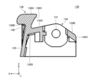
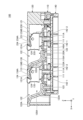
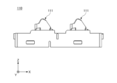
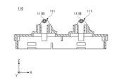
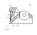
図1は、図10に示す切取り線A-Aにより切断した一実施形態に係る入力装置100が備えるノブ130の断面図である。図2は、一実施形態に係る入力装置100の外観斜視図である。図3は、一実施形態に係る入力装置100の平面図である。図4は、一実施形態に係る入力装置100の左側面図である。図5は、一実施形態に係る入力装置100の図2に示すA-A断面線による断面図である。図6は、一実施形態に係る入力装置100の分解斜視図である。図7は、一実施形態に係る入力装置100の図2に示すB-B断面線による断面図である。図8は、一実施形態に係る入力装置100が備えるノブ130の斜め上方から視た外観斜視図である。図9は、一実施形態に係る入力装置100が備えるノブ130の斜め下方から視た外観斜視図である。図10は、一実施形態に係る入力装置100が備えるノブ130の上面図である。図11は、一実施形態に係る入力装置100が備えるノブ130の下面図である。図12は、一実施形態に係る入力装置100が備える筐体110の上面図である。図13は、一実施形態に係る入力装置100が備える筐体110の側方図である。図14は、一実施形態に係る入力装置100が備える筐体110の下面図である。図15は、一実施形態に係る軸部111Bの位置を説明する断面図である。
図1は、図10に示す切取り線A-Aにより切断した一実施形態に係る入力装置100が備えるノブ130の断面図である。図2は、一実施形態に係る入力装置100の外観斜視図である。図3は、一実施形態に係る入力装置100の平面図である。図4は、一実施形態に係る入力装置100の左側面図である。図5は、一実施形態に係る入力装置100の図2に示すA-A断面線による断面図である。図6は、一実施形態に係る入力装置100の分解斜視図である。図7は、一実施形態に係る入力装置100の図2に示すB-B断面線による断面図である。図8は、一実施形態に係る入力装置100が備えるノブ130の斜め上方から視た外観斜視図である。図9は、一実施形態に係る入力装置100が備えるノブ130の斜め下方から視た外観斜視図である。図10は、一実施形態に係る入力装置100が備えるノブ130の上面図である。図11は、一実施形態に係る入力装置100が備えるノブ130の下面図である。図12は、一実施形態に係る入力装置100が備える筐体110の上面図である。図13は、一実施形態に係る入力装置100が備える筐体110の側方図である。図14は、一実施形態に係る入力装置100が備える筐体110の下面図である。図15は、一実施形態に係る軸部111Bの位置を説明する断面図である。
図2~図7に示す入力装置100は、自動車等の車両に設置され、電気的に駆動される車載装置(例えば、電動パワーウインドウ)の操作を行うための入力装置として利用することができる。
図2および図3に示すように、入力装置100は、前側(X軸正側)に左右方向(Y軸方向)に並べて設けられた2つのノブ130を備えており、後側(X軸負側)に左右方向(Y軸方向)に並べて設けられた2つのノブ230を備えている。入力装置100は、当該2つのノブ130および当該2つのノブ230に対して押圧する操作または引き上げる操作を行うことによって、4つの操作対象(例えば、電動パワーウインドウ)を駆動させることができる。
図2~図7に示すように、入力装置100は、筐体110、パネル部材120、2つのノブ130、2つのノブ230、カバー140、および8つのアクチュエータ150を備える。
筐体110は、下部が開口した中空構造を有する樹脂製且つ箱状の部材である。本実施形態では、筐体110は、略直方体形状を有する。例えば、筐体110は、射出成型法によって成形される。筐体110の内部には、カバー140が収容される。筐体110の上部には、2つのノブ130および2つのノブ230を揺動可能に支持するための、4つの支持部111が設けられている。4つの支持部111の各々は、板形状を有し、左右方向(Y軸方向)から視たとき、筐体110の上面110Aから上方(Z軸正方向)に突出した山形状を有して設けられている。
4つの支持部111の各々は、2つのノブ130および2つのノブ230の各々と対応する位置に設けられている。すなわち、4つの支持部111のうちの2つの支持部111は、筐体110の上面110Aにおける前側(X軸正側)に、左右方向(Y軸方向)に並べて設けられている。また、4つの支持部111のうちの他の2つの支持部111は、筐体110の上面110Aにおける後側(X軸負側)に、左右方向(Y軸方向)に並べて設けられている。
各支持部111は、上下方向(Z軸方向)に延設された略四角筒状を有する。各支持部111は、上記四角筒状を構成する、左右一対の垂直な壁状の外壁部111Aを有する。各支持部111は、左右一対の外壁部111Aの各々から内側に突出して設けられた一対の軸部111Bを有する。軸部111Bは、円柱形状を有し、ノブ130に形成される軸受孔131に嵌合され、ノブ130を揺動可能に支持する形状である。軸受孔131は、ノブ130の基部134に設けられた板形状を有するリブ134Cに形成される。軸受孔131は「仮想揺動中心軸」の一例である。軸部111Bおよび軸受孔131は、左右方向(Y軸方向)と平行に設けられる。ノブ130の基部134には、筐体110の支持部111と対向配置され、支持部111に対してリブ134Cとは反対の側に設けられる側壁部134Eを有する。側壁部134Eは、軸部111Bと軸受孔131とを外力から保護する保護壁であり、基部134の側方部の全体に設けられることによって基部134の物理的強度を補強する構造壁である。側壁部134Eには、Y軸方向において軸受孔131と対応する位置に設けられた貫通孔131Aが形成される。貫通孔131Aは、組立て工程において軸部111Bと軸受孔131との嵌合状態を目視で検査し易くするための覗き穴である。貫通孔131Aは、軸受孔131と同軸上に設けられることが好ましい。基部134の上部には、基部134を上下方向(Z軸方向)に貫通した貫通孔134Fが形成される。貫通孔134Fは、リブ134Cと側壁部134Eとによって構成されたZ軸方向に貫通した貫通孔である。貫通孔134Fを設けることによって、リブ134Cは弾性変形し易くなるため組立て易くなる。また、貫通孔134Fを設けた場合、例えば組立後に何かしらの不具合を発見して筐体110とノブ130とを分解したくなった時、支持部111とリブ134Cとの間に分解用の工具を差し込み易い。基部134の上部には、基部134を上下方向(Z軸方向)に貫通した貫通孔134Gが設けられる。貫通孔134Gは、カバー140上に設けられ、貫通孔134Gの下方に配置された光源(非図示)からの光を導光する導光穴である。
支持部111とリブ134Cとは板形状を有することにより、組立後、例えばノブ130に強い力が加えられて軸部111Bと軸受孔131とに高い負荷が掛かった時、支持部111とリブ134Cとは弾性変形することによって互いに追随して嵌合状態を維持する。このことによれば、筐体110とノブ130とは分解し難くなる。
図13~図15に示すように、本実施形態の筐体110の支持部111は、Y軸方向から視たとき、頂点を有する山形状を有している。そして、軸部111Bは、該山形状の頂部に設けられる。
図1に示すように、軸受孔131は、基部134の上部(Z軸正方向の部位)に設けられ、基部134および軸受孔131の強度が許容される限界までパネル上面部121との距離が小さくなるように調整される。
このことによって、図7に示すように、筐体110の軸部111Bとパネル上面部121とは、組立て後における貫通孔131Aとパネル上面部121との距離が基部134とパネル上面部121と緩衝しない限界値まで小さくなる。別の言葉で言いかえると、ノブ130の基部134に設けられた仮想揺動中心軸(貫通孔131A)は、パネル上面部121の下方の空間のうち、上下方向(Z軸方向)における最も高い位置に配置される。つまり、ノブ130は、パネル上面部121のすぐ近くに配置されるが、詳しくは後述する第1斜面部134Aと第2斜面部134Bとがノブ130の基部134の上端部に形成されることよって、揺動するノブ130はパネル上面部121と干渉することは無い。このことによれば、パネル上面部121から上面140A前の距離を増やすこと無く、ノブ130と上下方向にシフトするアクチュエータ150とが当接する位置からプッシュスイッチ142までの、上下方向(Z軸方向)における距離を大きくすることが容易となる。そのため、X軸方向における軸受孔131と第2押圧部133Bとの距離を近づけた場合であっても、第2押圧部133Bからアクチュエータ150-2の先端部151へと操作力が伝達される時に発生するモーメントの向きを上下方向(Z軸方向)に近づけることができる。このことによれば、ノブ130からアクチュエータ150-2へと効率的に操作力が伝達されるため、操作感触や操作荷重の設計が容易になる。また、このことによれば、操作力が伝達される際に損失する力がノブ130を破損させる可能性を小さくできる。また、力の損失による操作荷重の違和感が発生しない状態を維持したまま、X軸方向における軸受孔131と第2押圧部133Bとの距離を小さく設定することが容易になるため、入力装置100をX軸方向に小型化し易くなる。また、力の損失による操作荷重の違和感が発生しない状態を維持したまま、前後方向(X軸方向)における第2押圧部133Bの配置を調整し易くなるので、引っ張り操作を行った時の操作荷重の設計自由度が高くなる。そのため、例えば、押圧操作を行った時の操作荷重と引っ張り操作を行った時の操作荷重とを同程度に設定する等の手法によって、操作感触の観点においてバランスに配慮した設計をし易くなる。また、第1斜面部134Aと第2斜面部134Bとを設けることによって、ノブ130とパネル上面部121とが互いに緩衝し難くなった時、第2押圧部133Bとアクチュエータ150-1の先端部151とが接触する角度と、第1押圧部133Aとアクチュエータ150-2の先端部151とが接触する角度と、を揃えることは容易になる。このことによれば、操作部136を押圧操作する時の操作荷重と、操作部136を引っ張り操作する時の操作荷重と、を調整することは容易になる。例えば、押圧操作を行う時に必要となる操作力と引っ張り操作を行う時に必要となる力とを同じ大きさに揃えることは容易になる。
筐体110は、2つのノブ130および2つのノブ230の各々に対して、前後に並べて設けられた一対のガイド部112を有する。すなわち、筐体110は、合計で8つのガイド部112を有する。各ガイド部112は、上下方向に延設された円筒状を有する。
パネル部材120は、中空構造を有する樹脂製且つ箱状の部材である。該中空構造の内部には筐体110とノブ130の基部134とが配置される。本実施形態では、パネル部材120は、略直方体形状を有する。パネル部材120の内部には、筐体110および2つのノブ130および2つのノブ230が収容される。すなわち、パネル部材120は、筐体110の上方に設けられ、筐体110を覆う。パネル部材120は、例えば、車両の運転席のコンソールを構成する部材である。本実施形態において、パネル部材120と筐体110とは直接接してスナップイン結合で固定されるが、パネル部材120と筐体110とは他の部材を介して間接的に固定されていても良い。
パネル部材120は、XY平面に対して平行な平面形状のパネル上面部121を有する。パネル部材120のパネル上面部121には、上方(Z軸正方向)からの平面視にて左右方向(Y軸方向)を長手方向とする長方形状の開口部122が形成されている。特に、パネル上面部121には、2つの開口部122が、前後に並べて形成されている。開口部122は、操作者がノブ130の操作部136を引っ張り操作する際に指を差し入れる穴である。ノブ130の操作部136は、開口部122の後部に露出して配置されており、操作者からの操作力を受け付ける。
また、パネル部材120は、2つの開口部122の各々に対し、開口部122の前方(X軸正方向)の側を構成するパネル上面部121の一部(前端部122A)と、開口部122の下方にXY平面と略平行に設けられた底壁部123と、前端部122Aから下方へ延設され前端部122Aと底壁部123とを接続する接続部123Aと、を有する。図5および図7に示すように、底壁部123と接続部123Aとは、湾曲した形状を有しており、パネル部材120における開口部122の下方の空間120Aの前側(X軸正側)および下側(Z軸負側)を覆う。
2つのノブ130および2つのノブ230の各々は、操作者からの操作力を受け付けて揺動する樹脂製の部材である。2つのノブ130および2つのノブ230の各々は、略直方体形状を有しており、中空構造を有する。組立工程において、該中空構造には、下方の側から筐体110の支持部111が差し込まれる。2つのノブ130および2つのノブ230の各々は、筐体110の上方に配置され、筐体110の対応する支持部111に接続されることにより、筐体110に対して揺動可能に支持される。各ノブ130は、左右両側面の各々に、軸受孔131を有する。各ノブ130は、左右一対の軸受孔131の各々が、支持部111に設けられている左右一対の軸部111Bの各々に嵌め込まれることにより、筐体110に対して、左右一対の軸部111Bを仮想揺動中心軸として回転可能に支持される。各ノブ130は、詳しくは後述するメカストッパ124とプッシュスイッチ142-1のストロークの下端とによって回転ストロークの範囲が規定される。ノブ130が回転する時、操作部136は上方(Z軸正方向)および下方(Z軸負方向)に揺動する。各ノブ130は、XZ平面と平行なリブ134C(図8および図9参照)を2つ有している。2つのリブ134Cは、の該中空構造の左方の側と右方の側とにそれぞれ配置される。軸受孔131は、当該リブ134CをY軸方向に貫通するように形成されている。また、各ノブ130は、基部134の前方側の端部134D(「一端」の一例)と連続して形成される前壁部135を有する。図2に示すように、前壁部135は、ノブ130のX軸正方向の側を閉塞している。本実施形態では、前壁部135はYZ平面と略平行な板形状を有しているが、前壁部135は必ずしも平面形状を有している必要性は無い。前壁部135は、例えば、一部に曲面形状を含んでいても良く、起伏を有した形状でも良く、一部に波打った形状を含んでいても良い。図1および図7に示すように、前壁部135は、基部134の前方(X軸正方向)の側の端部134Dから開口部122の後方の側に向けて延設される。前壁部135の上方の側の端部には、XY平面と平行に延設され、操作者による操作を受け付ける操作部136を有する。なお、操作部136は、前壁部135と交差する方向、且つ、仮想揺動中心軸と平行な方向に延在していることが好ましく、操作部136はXY平面と平行に延設される必要は無い。操作部136をXY平面と平行に延設した場合、操作部136は寸法を小さく設定した場合であっても上方から視認し易くなる。操作部136は、中立状態において、開口部122の後方の側の端部に沿って配置される。別の言葉で言い換えると、前壁部135は、ノブ130の端部134Dから略上方に向けて延設される。図5~図7に示すように、パネル部材120は、開口部122を構成する内壁121BのX軸負側の部分に、ノブ130の操作部136と対向して設けられ、パネル上面部121と斜めに交差する向きに形成される対向部121A(「第1対向面部」)の一例)を有する。ノブ130の前壁部135の上方側の端部にはパネル上面部121と平行な操作部136が形成され、操作部136は、開口部122の後方の側に配置される。別の言葉で言い換えると、操作部136は、開口部122の後方の側を構成するパネル上面部121の対向部121Aと対向して配置され、対向部121Aの前方(X軸正方向)に配置される。操作部136のX軸負方向の側には対向部121Aと対向配置される対向部136C(「第2対向面部」)の一例)を有する。異物の侵入を抑制するため、中立状態において、対向部121Aと対向部136Cとの距離は、互いに干渉しないだけの大きさを保って可能な限り小さくなるように設定されることが好ましい。パネル部材120の対向部121A、および、ノブ130の対向部136Cは、微小な隙間を有して互いに平行な平面形状または曲面形状を有している。パネル部材120の対向部121A、および、ノブ130の対向部136Cの角度は、完全に平行である必要性は無く、ノブ130の動作を阻害しない範囲内であればズレがあっても良い。また、対向部121Aと対向部136Cとの距離を小さくする観点において、パネル部材120の対向部121A、および、ノブ130の対向部136Cは、ノブ130の仮想揺動中心軸を中心とした円柱の側面と同じ曲率を有し、この円柱の側面と重なる曲面形状を有していることが好ましい。図7に示すように、パネル部材120の対向部121A、および、ノブ130の対向部136Cは、パネル上面部121の成す平面方向(XY平面方向)に対して斜めに形成されることが好ましい。このことによれば、塵や水が貫通孔134Gから装置内へ侵入する可能性をより小さくできる。また、ノブ130とパネル上面部121との間に異物が挟まることによってノブ130の回動がスタックしてしまう不具合が発生する可能性を小さくできる。また、前壁部135は、ノブ130の端部134Dから略下方に向けて延設され基部134の前方側を閉塞する。図1に示すように、本実施形態において、概ね前壁部135は平面形状を有しているが、前壁部135は一部に曲面形状を有していても良い。
ノブ130の内部空間130Aにおいて、左右一対の軸受孔131よりも前側(X軸正側)には、第1押圧部133Aが設けられている。第1押圧部133Aは、下向きの水平な平面部分であり、アクチュエータ150-1の先端部151に当接しており、ノブ130が下方(Z軸負方向)に揺動したときに、アクチュエータ150-1を押圧する。
ノブ130の内部空間130Aにおいて、左右一対の軸受孔131よりも後側(X軸負側)には、第2押圧部133Bが設けられている。第2押圧部133Bは、下向きの水平な平面部分であり、アクチュエータ150-2の先端部151に当接しており、ノブ130が上方(Z軸正方向)に揺動したときに、アクチュエータ150-2を押圧する。
カバー140は、筐体110の下側開口部110Bに嵌め込まれることにより、下側開口部110Bを閉塞する、硬質な樹脂製且つ平板状の部材である。カバー140は、上方からの平面視にて、前後方向(X軸方向)を長手方向とする長方形状を有する。カバー140の上面140Aは、基板として機能し、各種電子部品が実装される。カバー140の側面には、複数の係合爪141が設けられている。
カバー140は、複数の係合爪141が、筐体110の側面に形成されている複数の開口部114の各々に係合することにより、上面140AがXY平面に対して平行となる姿勢で、筐体110に固定される。本実施形態において、カバー140は一つの部材として説明するが、カバー140は基板と樹脂部材とを組み合わせたものであっても良い。
カバー140の上面140Aにおいて、2つのノブ130および2つのノブ230の各々の下側には、プッシュスイッチ142-1を前側(X軸正側)にして、2つのプッシュスイッチ142-1,142-2が、前後方向(X軸方向)に並べて配置されている。すなわち、カバー140の上面140Aには、合計8つのプッシュスイッチ142(「ノブによって押圧される接点」の一例)が配置されている。プッシュスイッチ142は、所定の押圧量以上に押圧された際に、信号を生成するスイッチ機構である。なお、本実施形態では、プッシュスイッチ142の一例として、タクトスイッチ(登録商標)を用いているが、プッシュスイッチ142は、ノブ130が回転した時に切り替わる電気的要素であれば良く、タクトスイッチ(登録商標)でなくても良い。プッシュスイッチ142はラバードームスイッチであっても良い。プッシュスイッチ142は、反転動作可能な2つの復帰部材を内蔵するダブルアクションタイプのタクトスイッチ(登録商標)であっても良い。また、本願の接点は、上記のような接点機構の内部に接点部材と復帰部材とが内蔵されたものに限らず、連動するように設定された接点部材と復帰部材との組合せであってもよい。例えば、プッシュスイッチ142は、圧力センサーと復帰部材とを組み合わせて構成された信号生成機構であっても良い。プッシュスイッチ142は、例えばノブ130の回転ストロークを上面140Aと平行な直線ストロークに置き換える力変換部材と摺動接点機構と復帰部材とを組み合わせて構成された検出信号生成機構であっても良い。プッシュスイッチ142は、例えば赤外線センサー等を含んでノブ130とカバー140の上面140Aとの距離を検出可能な光学検出機構と復帰部材とを組み合わせて構成される信号生成機構であっても良い。
8つのアクチュエータ150の各々は、対応するプッシュスイッチ142の上方に配置される、樹脂製且つ円柱状の部材である。各アクチュエータ150は、筐体110のガイド部112内に、上下方向(Z軸方向)に移動可能に配置される。アクチュエータ150は、曲面状の先端部151が上向きとなるように、ガイド部112の内部に配置される。
入力装置100は、4つのプッシュスイッチ142の各々に対して、前側(X軸正側)のアクチュエータ150-1と、後側(X軸負側)のアクチュエータ150-2とを有する。
アクチュエータ150-1は、先端部151が、ノブ130の第1押圧部133Aに当接しており、下面152が、プッシュスイッチ142-1の上面に当接している。アクチュエータ150-2は、先端部151が、ノブ130第2押圧部133Bに当接しており、下面152が、プッシュスイッチ142-2の上面に当接している。
(入力装置100の動作)
以上のように構成された入力装置100は、ノブ130の操作がなされていないとき、ノブ130の第1押圧部133Aおよび第2押圧部133Bに対し、プッシュスイッチ142-1およびプッシュスイッチ142-2から、アクチュエータ150-1およびアクチュエータ150-2介して、前後均等に上方へ付勢されている。これにより、ノブ130の操作がなされていないとき、ノブ130は、中立状態を維持できる。
以上のように構成された入力装置100は、ノブ130の操作がなされていないとき、ノブ130の第1押圧部133Aおよび第2押圧部133Bに対し、プッシュスイッチ142-1およびプッシュスイッチ142-2から、アクチュエータ150-1およびアクチュエータ150-2介して、前後均等に上方へ付勢されている。これにより、ノブ130の操作がなされていないとき、ノブ130は、中立状態を維持できる。
そして、操作者によってノブ130の操作部136を引き上げる操作がなされたとき、ノブ130が前上がりに揺動し、ノブ130の第2押圧部133Bが、アクチュエータ150-2を介して、プッシュスイッチ142-2を押圧する。これにより、プッシュスイッチ142-2は、スイッチオン状態に切り替わり、検出信号を出力する。
また、操作者によってノブ130の操作部136を押し下げる操作がなされたとき、ノブ130が前下がりに揺動し、ノブ130の第1押圧部133Aが、アクチュエータ150-1を介して、プッシュスイッチ142-1を押圧する。これにより、プッシュスイッチ142-1は、スイッチオン状態に切り替わり、検出信号を出力する。
さらに、ノブ130の操作が解除されたとき、ノブ130は、プッシュスイッチ142-1またはプッシュスイッチ142-2からの付勢力を利用して、中立状態に復帰し、中立状態を維持する。
ここで、一実施形態に係る入力装置100において、ノブ130は、筐体110が有する支持部111によって揺動可能に支持される仮想揺動中心軸を有し、パネル上面部121によって覆われる基部134を有する。
また、ノブ130は、前壁部135と、操作部136とを有する。前壁部135は、仮想揺動中心軸の軸方向と平行な板形状を有し、少なくとも一部が基部134の開口部122に近い側の一端から開口部122に向けて延在する。操作部136は、前壁部135の開口部122の側の端部に設けられ、操作者からの操作力を受け付ける。
そして、ノブ130の操作部136は、押圧操作面部136Aと、引っ張り操作面部136Bと、第1のリブ137と、を有する。押圧操作面部136Aは、平面形状を有する。押圧操作面部136Aは、操作部136に対する操作力から解放された中立状態において、パネル上面部121と同一平面上に設けられる。引っ張り操作面部136Bは、操作部136における押圧操作面部136Aの背面側に形成され、前壁部135と交差して凹形状部を形成する。別の言葉で言い換えると、引っ張り操作面部136Bは、Y軸方向から視たとき、操作部136と前壁部135とが交差して成す内角である。引っ張り操作面部136Bは、押圧操作面部136Aの背面側、且つ、仮想揺動中心軸(貫通孔131A)から遠い側に、凹形状部を形成する。第1のリブ137は、上記凹形状部に設けられ、前壁部135と引っ張り操作面部136Bとを繋いで仮想揺動中心軸の軸方向と垂直な平面方向に延在する。第1のリブ137は、仮想揺動中心軸の軸方向における前壁部135の一方側の縁部と他方側の縁部とに一対設けられる。別の言葉で言い換えると、第1のリブ137は、仮想揺動中心軸方向に離間して前壁部135に一対設けられる。
これにより、一実施形態に係る入力装置100は、操作者の指によって操作部136の引き上げる操作を行う際に、引っ張り操作面部136Bによって操作者の指を確実に掛止することができ、よって、当該操作を確実に行うことができる。
特に、本実施形態では、操作部136は、左右方向(Y軸方向)から視て略四半円形状を有しており、操作部136の下面である引っ張り操作面部136Bは、水平面となっている。これにより、一実施形態に係る入力装置100は、操作者の指によって操作部136の引き上げる操作を行う際に、引っ張り操作面部136Bからの操作者の指の滑り落ちを抑制することができ、よって、当該操作をより確実に行うことができる。
また、操作部136の押圧操作面部136Aは、XY平面に対して平行な平面状を有しており、且つ、パネル部材120のパネル上面部121と同一平面上にある。
これにより、一実施形態に係る入力装置100は、操作部136がパネル上面部121よりも突出しないようにすることができ、操作部136に物体が引っ掛かり難くすることができるため、操作部136の引き上げる操作が誤操作されてしまうことを抑制することができる。
なお、「同一平面上」とは、押圧操作面部136Aの高さ位置とパネル上面部121の高さ位置とが完全に一致する場合に限らず、押圧操作面部136Aの高さ位置がパネル上面部121の高さ位置よりも僅かに高い位置にある場合、および、押圧操作面部136Aの高さ位置がパネル上面部121の高さ位置よりも僅かに低い位置にある場合も含む。本実施形態において、中立状態のノブ130の押圧操作面部136Aは、パネル上面部121に対する上下方向の相対位置がパネル上面部121より0.1mm高い位置に配置されている。また、本実施形態では、押圧操作面部136Aを下方へ押圧して1.4mm遷移させた時、プッシュスイッチ142-1は1.5mm以上(「所定の量以上」の一例)押圧されると、信号を生成する。そのため、例えば、操作者がパネル上面部121の上に肘をつく等の行為を行うことによって押圧操作面部136Aが押圧され、押圧操作面部136Aがパネル上面部121と同じ高さまで0.1mm遷移した時には、ノブ130のプッシュスイッチ142-1への押圧量は、信号を生成するための所定の量である1.5mmよりも小さいため、プッシュスイッチ142-1は信号を生成しない。もともと押圧操作面部136Aの高さ位置がパネル上面部121の高さ位置よりも低い位置に設定される場合には、操作者がパネル上面部121の上に肘をついても押圧操作面部136Aは押圧されず遷移しないので、プッシュスイッチ142-1が信号を生成することは無い。なお、本実施形態の構成では、パネル上面部121がノブ130の基部134の上方を覆っているため、操作者がパネル上面部121の上に肘をつく等の行為を行った時、ノブ130が誤って上記とは反対の方向に回転してしまう可能性は無いので、後側のプッシュスイッチ142-2が押圧される虞は無い。
また、ノブ130の基部134は、ノブ130の仮想揺動中心軸の軸方向(すなわち、Y軸方向)から視たときに、仮想揺動中心軸(すなわち、軸受孔131)よりも前側(X軸正側)に設けられ、前下がりに傾斜した第1斜面部134Aと、仮想揺動中心軸(すなわち、軸受孔131)よりも後側(X軸負側)に設けられ、後下がりに傾斜した第2斜面部134Bとを有する山形状を有する。同じことを別の言葉で表現すると、基部134は、ノブ130の仮想揺動中心軸の軸方向(Y軸方向)から視たとき、ノブ130の仮想揺動中心軸よりもパネル上面部121の側で、且つ、開口部122に近い側に設けられ、パネル上面部121に対して開口部122との距離が近くなるにつれパネル上面部121との距離が大きくなる向きに傾斜した第1斜面部134Aを有する。また、基部134は、ノブ130の仮想揺動中心軸の軸方向(Y軸方向)から視たとき、パネル上面部121の側の、ノブ130の仮想揺動中心軸に対して第1斜面部134Aとは反対の側に設けられ、パネル上面部121に対して開口部122との距離が遠くなるにつれパネル上面部121との距離が大きくなる向きに傾斜した第2斜面部134Bとを有する。本実施形態において、第1斜面部134Aは平面形状を有しているが、パネル上面部121に対する傾斜する向きの傾向が上記と同じであれば良く、第1斜面部134Aは曲面形状を有していても良い。第2斜面部134Bも同様である。
これにより、一実施形態に係る入力装置100は、ノブ130の仮想揺動中心軸(すなわち、軸受孔131)を、パネル上面部121により近づけることができ(すなわち、ノブ130の仮想揺動中心軸の高さ位置をより高めることができ)、且つ、基部134が上記山形状を有することによって、ノブ130の揺動時に基部134がパネル上面部121に干渉しないようにすることができる。
また、図5および図7に示すように、パネル部材120のパネル上面部121は、当該パネル上面部121の下面(ノブ130の第1斜面部134Aと対向配置される側の面)、且つ、開口部122の後側(X軸負側)に、第1斜面部134Aに向けて突出して設けられた突起状のメカストッパ124を有する。メカストッパ124は、ノブ130の基部134の第1斜面部134Aと所定距離離間して対向しており、ノブ130が上方に所定量揺動したときに、第1斜面部134Aの前端部(X軸正側の端部)と当接する。
これにより、一実施形態に係る入力装置100は、ノブ130の上方への揺動量を所定量に規制することができる。また、一実施形態に係る入力装置100は、メカストッパ124を、基部134の第1斜面部134Aにおける前端部(すなわち、操作部136の近傍)に当接させることで、メカストッパ124による抑止力を効率的に操作者の指に伝達することができ、ノブ130全体が撓むことを抑制できるため、ノブ130の破損を抑制できる。
また、図8および図9に示すように、ノブ130は、前壁部135と操作部136とが成す角部138に設けられた一対の第1のリブ137を、ノブ130の仮想揺動中心軸の軸方向(Y軸方向)における両端部に有する。本実施形態では、一例として、第1のリブ137は、垂直な略三角形状の板状を有しており、上辺が操作部136に接続されており、後辺が前壁部135に接続されている。
これにより、一実施形態に係る入力装置100は、操作部136の強度を高めることができ、操作部136の破損を防止することができる。また、一実施形態に係る入力装置100は、一対の第1のリブ137のノブ130の仮想揺動中心軸の軸方向(Y軸方向)における両端部に設けたため、操作者の指によって操作部136の引き上げる操作を行う際に、一対の第1のリブ137の間に操作者の指を挿し込むことができ、一対の第1のリブ137が当該操作の邪魔にならないようにすることができる。なお、前壁部135と操作部136とが成す角部138は、「凹形状部」の一例であり、鋭角である。別の言葉で言い換えると、操作部136の裏面側(Z軸負方向の側)、且つ、ノブ130の仮想揺動中心軸から遠い側(X軸正方向の側)の操作部136と前壁部135とが交差して成す内角は鋭角である。別の言葉で言い換えると、図1に示すように、Y軸方向から視たとき、前壁部135と操作部136とが成す形状は、アラビア数字の「7」と似た形状になる。
(好適な寸法の一例)
図16は、一実施形態に係る入力装置100における好適な寸法の一例を示す透過図である。図16の図中に描かれた点線は、パネル上面部121の下方に配置される基部134とその後端部134Hとの位置を示している。
図16は、一実施形態に係る入力装置100における好適な寸法の一例を示す透過図である。図16の図中に描かれた点線は、パネル上面部121の下方に配置される基部134とその後端部134Hとの位置を示している。
図16に示すように、前後方向(X軸方向)における操作部136の寸法を幅L1とし、ノブ130全体の寸法から操作部136が占める幅の寸法を差し引いた寸法を幅L2とする。また、前後方向(X軸方向)における開口部122の寸法からL1を差し引いた寸法を幅L3とする。幅L1は、平均的な成人男性が操作部136を指先で押圧操作する際、違和感無く押圧するために最低限必要となる寸法に設定されることが好ましい。幅L3は、成人男性が引っ張り操作を行う際、開口部122に指先を差し込むために必要な寸法に設定される。幅L2は、幅L1、幅L3、押圧操作を行った時の操作荷重、引っ張り操作を行った時の操作荷重、基部134の後端部134Hとパネル部材120の前端部122Aとが干渉しない条件を考慮した上で設定される。一般的な市場ニーズとして入力装置は小型であることが求められる傾向を考慮すると、幅L2は可能な限り小さく設定されることが好ましい。
本実施形態では、前後方向(X軸方向)における操作部136の幅L1は6mmである。また、前後方向(X軸方向)におけるノブ130全体の寸法から操作部136の寸法を差し引いた幅L2は、12mmである。すなわち、操作部136の幅L1と、ノブ130全体の寸法から操作部136の寸法を差し引いた幅L2との比は、6:12である。なお、幅L1が6mmである場合、幅L2は11mmから13mmの間であることが好ましい。別の言葉で説明すると、寸法比を比較する場合、幅L1の値を1とすると、幅L2の値は1.8~2.2の間であることが好ましい。幅L2を10mm以下に設定した場合、押圧操作を行った時の操作荷重と引っ張り操作を行った時の操作荷重とを同程度の大きさに設定することは困難となるため、操作感触のバランスが悪くなる。幅L2を14mm以上に設定した場合、入力装置は大型化する。本実施形態の入力装置100は、基部134が第1斜面部134A、第2斜面部134Bを有するため、幅L2を好適な値に設定し易い。
また、本実施形態では、前後方向(X軸方向)における開口部122の寸法(28mm)から幅L1を差し引いた寸法(幅L3)は、22mmである。すなわち、開口部122の寸法から幅L1を差し引いた寸法L3と、操作部136の寸法L1との比は、22:6である。幅L3は、小型化を求める市場ニーズの観点から、成人男性が開口部122に指先を差し込むことが可能なだけの大きさを保って、可能な限り小さく設定されることが好ましい。一方、操作者が入力装置100を目視せずにブラインドタッチで操作を行う際、触感を頼りに操作を行うべき位置を探し易くなるように、前端部122Aから接続部123Aにかけての形状は所定の曲率半径を有した曲面形状を有していることが好ましい。前端部122Aから接続部123Aにかけて曲面形状が形成されている場合、操作者は触感を頼りに操作部136を探し当てることが容易になる。前端部122Aから接続部123Aにかけて曲面形状を形成しない場合、幅L3が必要とする最低限の寸法は11mmである。接続部123Aに設けられる曲面の曲率半径の大きさ如何によって幅L3は大きく設定される。操作性を良好に保つ観点において、幅L3は、11mmから22mmの範囲に設定されることが好ましい。別の言葉で説明すると、寸法比を比較する場合、幅L1の値を1とすると、幅L3の値は1.8~3.7の間であることが好ましい。
(ノブ130の変形例1)
図17は、一実施形態に係る入力装置が備えるノブ130の変形例1の上方斜視図である。図18は、一実施形態に係る入力装置が備えるノブ130の変形例1の上面図である。図19は、一実施形態に係る入力装置が備えるノブ130の変形例1の下面図である。図20は、一実施形態に係るノブ130の変形例1が有する第2のリブ238を説明する断面図である。
図17は、一実施形態に係る入力装置が備えるノブ130の変形例1の上方斜視図である。図18は、一実施形態に係る入力装置が備えるノブ130の変形例1の上面図である。図19は、一実施形態に係る入力装置が備えるノブ130の変形例1の下面図である。図20は、一実施形態に係るノブ130の変形例1が有する第2のリブ238を説明する断面図である。
図17~図20に示すノブ230は、一実施形態に係るノブ130の変形例1である。図17~図20に示すように、ノブ230は、前壁部235からX軸負方向の側に、XZ平面と平行に延在する第2のリブ238を有する。第2のリブ238の上方側(Z軸正側)の端面は、第1斜面部234Aとなっている。ノブ230のY軸方向から視たとき、第1斜面部234Aは、ノブ230の基部234の仮想揺動中心軸(すなわち、軸受孔231)よりもX軸正側に設けられる。また、ノブ230は、基部234の仮想揺動中心軸(すなわち、軸受孔131)よりも後側(X軸負側)に設けられ、後下がりに傾斜した第2斜面部234Bを有する。図17~図20に示す例では、ノブ230は、Y軸方向に並べて設けられた4つの第2のリブ238を有する。4つの第2のリブ238の各々は、仮想揺動中心軸の軸方向(Y軸方向)に対して垂直な壁となっている。
これにより、ノブ230は、前壁部235と基部234とを補強することができ、操作部236が操作を受け付けたときの前壁部235の変形を抑制することができる。
ノブ230は、本願の他の実施形態よりも生産性において優れた構成を有する。図20に示すXZ平面と平行な方向(W1方向、W2方向)は、樹脂成形法を用いてノブ230を製造する時に金型を抜く方向である。軸受孔231を除いたノブ230を構成する全ての形状は、金型を抜く方向(W1方向、W2方向)と衝突しない。金型を抜くために必要とされる作業力を小さくするため、軸受孔231を除いたノブ230を構成する全ての形状は、金型を抜く方向(図20に示すW1方向、W2方向)に対して斜め交差する形状に設定されることが好ましい。仮想揺動中心軸の軸方向(Y軸方向)から視たとき、操作部236と前壁部235とが交差して成す内角は鋭角に設定される。また、仮想揺動中心軸の軸方向(Y軸方向)から視たとき、前壁部235と第1斜面部234Aとが交差して成す内角は鋭角に設定される。仮想揺動中心軸の軸方向(Y軸方向)から視たとき、操作部236と前壁部235と第1斜面部234Aとは、アルファベットの「Z」と似た形状になる。
(ノブ130の変形例2)
図21は、一実施形態に係るノブ130の変形例2が有する貫通孔を説明する断面図である。図21に示すノブ330は、一実施形態に係るノブ130の変形例2である。図21に示すように、ノブ330は、前壁部335における端部334Dよりも操作部336の側に、前壁部335を貫通する貫通孔335Aを有する。これにより、ノブ330は、前壁部335と第1斜面部334Aとの間に浸入した水を貫通孔335Aから排出することができる。別の言葉で言い換えると、ノブ330の前壁部335には、操作部336とパネル上面部121との隙間から被水した水をノブ330の外側に排水するための貫通孔335Aが形成される。
図21は、一実施形態に係るノブ130の変形例2が有する貫通孔を説明する断面図である。図21に示すノブ330は、一実施形態に係るノブ130の変形例2である。図21に示すように、ノブ330は、前壁部335における端部334Dよりも操作部336の側に、前壁部335を貫通する貫通孔335Aを有する。これにより、ノブ330は、前壁部335と第1斜面部334Aとの間に浸入した水を貫通孔335Aから排出することができる。別の言葉で言い換えると、ノブ330の前壁部335には、操作部336とパネル上面部121との隙間から被水した水をノブ330の外側に排水するための貫通孔335Aが形成される。
(ノブ130の変形例3)
図22は、一実施形態に係るノブ130の変形例3が有する貫通孔を説明する断面図である。図22に示すノブ430は、一実施形態に係るノブ130の変形例3である。ノブ430は、Y軸方向に対して垂直に設けられた一対の側壁部434Eを有する。図22に示すように、ノブ430は、側壁部434Eにおける端部434Dよりも操作部436の側に側壁部434Eを貫通する貫通孔434Iを有する。これにより、ノブ430は、壁部435と第1斜面部434Aとの間に浸入した水を貫通孔434Iから排出することができる。別の言葉で言い換えると、ノブ430の仮想揺動中心軸方向(Y軸方向)に垂直な側壁部434Eには操作部436とパネル上面部121との隙間から被水した水をノブ430の外側に排水するための貫通孔434Iが形成される。
図22は、一実施形態に係るノブ130の変形例3が有する貫通孔を説明する断面図である。図22に示すノブ430は、一実施形態に係るノブ130の変形例3である。ノブ430は、Y軸方向に対して垂直に設けられた一対の側壁部434Eを有する。図22に示すように、ノブ430は、側壁部434Eにおける端部434Dよりも操作部436の側に側壁部434Eを貫通する貫通孔434Iを有する。これにより、ノブ430は、壁部435と第1斜面部434Aとの間に浸入した水を貫通孔434Iから排出することができる。別の言葉で言い換えると、ノブ430の仮想揺動中心軸方向(Y軸方向)に垂直な側壁部434Eには操作部436とパネル上面部121との隙間から被水した水をノブ430の外側に排水するための貫通孔434Iが形成される。
(入力装置100の変形例)
図23は、一実施形態に係るノブ130の変形例4を備える入力装置500の外観斜視図である。図24は、一実施形態に係るノブ130の変形例4の斜視図である。入力装置500は、導光穴の無いノブ530(「ノブ」の一例)を備えている。そのため、入力装置500は照光表示機能を有していない。図24に示すように、入力装置500のノブ530は、基部534に導光のための貫通孔が形成されておらず、第1斜面部534Aと第2斜面部534Bとが連続しているため、基部534は他の実施形態における基部よりも構造的に強い。このため、特に第2斜面部534Bの周辺部における構造的な強度に余裕があるため、基部534の後端部534Hを寸法的に前側に切り詰めても第2斜面部534Bの周辺部が破壊する虞は小さくなる。即ち、前後方向(X軸方向)における基部534の寸法を小さくできるので、入力装置500の寸法を小さくできる。また、入力装置100のパネル上面部121は、平面視した時の外輪郭の大きさがパネル部材120全体の外輪郭と同じであったが、平面視した時の入力装置500のパネル上面部521(「パネル上面部」の一例)は、パネル部材520の外輪郭の大きさよりも小さい。入力装置500のその他の構成については、入力装置100と同様である。
図23は、一実施形態に係るノブ130の変形例4を備える入力装置500の外観斜視図である。図24は、一実施形態に係るノブ130の変形例4の斜視図である。入力装置500は、導光穴の無いノブ530(「ノブ」の一例)を備えている。そのため、入力装置500は照光表示機能を有していない。図24に示すように、入力装置500のノブ530は、基部534に導光のための貫通孔が形成されておらず、第1斜面部534Aと第2斜面部534Bとが連続しているため、基部534は他の実施形態における基部よりも構造的に強い。このため、特に第2斜面部534Bの周辺部における構造的な強度に余裕があるため、基部534の後端部534Hを寸法的に前側に切り詰めても第2斜面部534Bの周辺部が破壊する虞は小さくなる。即ち、前後方向(X軸方向)における基部534の寸法を小さくできるので、入力装置500の寸法を小さくできる。また、入力装置100のパネル上面部121は、平面視した時の外輪郭の大きさがパネル部材120全体の外輪郭と同じであったが、平面視した時の入力装置500のパネル上面部521(「パネル上面部」の一例)は、パネル部材520の外輪郭の大きさよりも小さい。入力装置500のその他の構成については、入力装置100と同様である。
以上、本発明の一実施形態について詳述したが、本発明はこれらの実施形態に限定されるものではなく、特許請求の範囲に記載された本発明の要旨の範囲内において、種々の変形または変更が可能である。
本国際出願は、2024年1月5日に出願した日本国特許出願第2024-000829号に基づく優先権を主張するものであり、当該出願の全内容を本国際出願に援用する。
100,100-2 入力装置
110 筐体
110A 上面
110B 下側開口部
111 支持部
111A 外壁部
111B 軸部
111C 基部
112 ガイド部
114 開口部
120 パネル部材
120A 空間
121 パネル上面部
121A 対向部
122 開口部
123 底壁部
124 メカストッパ
130 ノブ
130A 内部空間
131 軸受孔
133A 第1押圧部
133B 第2押圧部
134 基部
134A 第1斜面部
134B 第2斜面部
134C リブ
134D 端部(一端)
134E 側壁部
134F 貫通孔
134G 貫通孔
134H 後端部
135 前壁部
136 操作部
136A 押圧操作面部
136B 引っ張り操作面部
136C 対向部
137 第1のリブ
138 角部
140 カバー
140A 上面
141 係合爪
142,142-1,142-2 プッシュスイッチ(接点)
150,150-1,150-2 アクチュエータ
151 先端部
152 下面
230 ノブ
234A 第1斜面部
234D 端部(一端)
235 前壁部
238 第2のリブ
330 ノブ
335 前壁部
334A 第1斜面部
334D 端部(一端)
335A 貫通孔
338 第2のリブ
430 ノブ
434E 側壁部
434I 貫通孔
500 入力装置
530 ノブ
534 基部
534A 第1斜面部
534B 第2斜面部
534H 後端部
110 筐体
110A 上面
110B 下側開口部
111 支持部
111A 外壁部
111B 軸部
111C 基部
112 ガイド部
114 開口部
120 パネル部材
120A 空間
121 パネル上面部
121A 対向部
122 開口部
123 底壁部
124 メカストッパ
130 ノブ
130A 内部空間
131 軸受孔
133A 第1押圧部
133B 第2押圧部
134 基部
134A 第1斜面部
134B 第2斜面部
134C リブ
134D 端部(一端)
134E 側壁部
134F 貫通孔
134G 貫通孔
134H 後端部
135 前壁部
136 操作部
136A 押圧操作面部
136B 引っ張り操作面部
136C 対向部
137 第1のリブ
138 角部
140 カバー
140A 上面
141 係合爪
142,142-1,142-2 プッシュスイッチ(接点)
150,150-1,150-2 アクチュエータ
151 先端部
152 下面
230 ノブ
234A 第1斜面部
234D 端部(一端)
235 前壁部
238 第2のリブ
330 ノブ
335 前壁部
334A 第1斜面部
334D 端部(一端)
335A 貫通孔
338 第2のリブ
430 ノブ
434E 側壁部
434I 貫通孔
500 入力装置
530 ノブ
534 基部
534A 第1斜面部
534B 第2斜面部
534H 後端部
Claims (17)
- 筐体と、
前記筐体を覆うパネル部材と、
操作者によって操作されるノブと、
前記ノブによって所定の押圧量以上に押圧された際に、信号を生成する接点と
を備え、
前記パネル部材は、
平面形状を有するパネル上面部と、
前記パネル上面部に形成され、前記ノブの少なくとも一部を露出する開口部と
を有し、
前記ノブは、
前記筐体によって支持される仮想揺動中心軸を有し、前記パネル上面部によって覆われて前記仮想揺動中心軸の周りを揺動する基部と、
前記基部に設けられ、前記開口部の下方から前記開口部に向けて延在する前壁部と、
前記前壁部の端部に設けられ、前記開口部から前記露出して前記操作者からの操作力を受け付ける操作部と
を有し、
前記操作部は、前記操作者に押圧される押圧操作面部を有し、
前記仮想揺動中心軸方向から視たとき、前記押圧操作面部の前記パネル上面部に対する上下方向の相対位置は、前記操作力から解放された中立状態では前記パネル上面部より上方に位置し、前記中立状態から前記操作力によって押圧された前記押圧操作面部が前記パネル上面部と同一平面上になるまで遷移した時には、前記ノブによる前記接点の前記押圧量が前記所定の量より小さくなり、前記接点が前記信号を生成しない位置に設けられ、
前記操作力によってさらに押圧された前記押圧操作面部が前記パネル上面部よりも下方に遷移した時には、前記ノブによる前記接点の前記押圧量が前記所定の量以上となり、前記接点が前記信号を生成する位置に設けられる
ことを特徴とする入力装置。 - 前記基部は、
前記仮想揺動中心軸方向から視たとき、前記仮想揺動中心軸よりも前記パネル上面部の側で、且つ、前記開口部に近い側に設けられ、前記パネル上面部に対して前記開口部との距離が近くなるにつれ前記パネル上面部との距離が大きくなる向きに傾斜した第1斜面部と、
前記仮想揺動中心軸方向から視たとき、前記仮想揺動中心軸に対して前記第1斜面部とは前後方向の反対の側に設けられ、前記パネル上面部に対して前記開口部との距離が遠くなるにつれ前記パネル上面部との距離が大きくなる向きに傾斜した第2斜面部と
を有する
ことを特徴とする請求項1に記載の入力装置。 - 前記仮想揺動中心軸方向から視たとき、前記操作部の前記押圧操作面部の裏面側、且つ、前記仮想揺動中心軸から遠い側の前記操作部と前記前壁部とが交差して成す内角は鋭角である
ことを特徴とする請求項1に記載の入力装置。 - 前後方向における、前記操作部の幅の値を1としたとき、前記ノブの前後方向の全体の寸法から前記操作部の幅の寸法を差し引いた寸法の値は1.8~2.2の間である
ことを特徴とする請求項1に記載の入力装置。 - 前後方向における、前記操作部の幅を6mmとしたとき、前記ノブの前後方向の全体の寸法から前記操作部の幅の寸法を差し引いた寸法は、12mmである
ことを特徴とする請求項4に記載の入力装置。 - 前後方向における、前記操作部の幅の値を1としたとき、前記開口部の前後方向の全体の寸法から前記操作部の幅の寸法を差し引いた寸法の値は1.8~3.7の間である
ことを特徴とする請求項1に記載の入力装置。 - 前後方向における、前記操作部の幅を6mmとしたとき、前記開口部の前後方向の全体の寸法から前記操作部の幅の寸法を差し引いた寸法は、22mmである
ことを特徴とする請求項6に記載の入力装置。 - 前記ノブは、
前記仮想揺動中心軸方向から視たとき、前記操作部と前記前壁部とが交差して成す内角で、前記操作部の前記押圧操作面部の背面側、且つ、前記仮想揺動中心軸から遠い側に、凹形状部を形成して引っ張り操作面部と成し、
前記凹形状部内に設けられ、前記前壁部と前記引っ張り操作面部とを繋いで前記仮想揺動中心軸方向と垂直な平面方向に延在する第1のリブと、を有する
ことを特徴とする請求項2に記載の入力装置。 - 前記第1のリブは、前記仮想揺動中心軸方向に離間して前記前壁部に一対設けられる
ことを特徴とする請求項8に記載の入力装置。 - 前記ノブは、
前記前壁部に設けられ、端面が前記基部の前記第1斜面部を成す、前記仮想揺動中心軸方向と垂直な平面方向に延在する第2のリブを有する
ことを特徴とする請求項2に記載の入力装置。 - 前記パネル部材は、
前記ノブの前記第1斜面部に向けて延在し、前記ノブが前記引っ張り操作面部に対する引っ張り操作にて所定量揺動したときに前記ノブの前記第1斜面部と当接するメカストッパを有する
ことを特徴とする請求項8に記載の入力装置。 - 前記ノブの前記前壁部には、前記操作部と前記パネル上面部の前記開口部との隙間から被水した水を前記ノブの外側に排水するための貫通孔が形成される
ことを特徴とする請求項2に記載の入力装置。 - 前記ノブは前記仮想揺動中心軸方向に垂直な一対の側壁部を有し、前記側壁部には前記操作部と前記パネル上面部の前記開口部との隙間から被水した水を前記ノブの外側に排水するための貫通孔が形成される
ことを特徴とする請求項2に記載の入力装置。 - 前記パネル部材は、前記開口部を構成する内壁に前記ノブの前記操作部と対向して設けられ、前記パネル上面部と斜めに交差する向きに形成される第1対向面部を有し、
前記ノブの前記操作部は、前記中立状態において、前記第1対向面部と微小な隙間を有して平行となる第2対向面部を有する
ことを特徴とする請求項1に記載の入力装置。 - 前記押圧操作面部は、平面形状を有し、前記中立状態において、前記パネル上面部と平行に設けられる
ことを特徴とする請求項1に記載の入力装置。 - 筐体と、
前記筐体を覆うパネル部材と、
操作者によって操作されるノブと、
前記ノブによって所定の押圧量以上に押圧された際に、信号を生成する接点と
を備え、
前記パネル部材は、
平面形状を有するパネル上面部と、
前記パネル上面部に形成され、前記ノブの少なくとも一部を露出する開口部と
を有し、
前記ノブは、
前記筐体によって支持される仮想揺動中心軸を有し、前記パネル上面部によって覆われて前記仮想揺動中心軸の周りを揺動する基部と、
前記基部に設けられ、前記基部の前記開口部の側のから前記開口部に向けて延在する前壁部と、
前記前壁部に設けられ、前記開口部から前記露出し、前記操作者からの操作力を受け付ける操作部と
を有し、
前記操作部の前記仮想揺動中心軸の側は、前記仮想揺動中心軸を中心とした円柱の側面と同じ曲率を有し、前記円柱の側面と重なる曲面形状を有している
ことを特徴とする入力装置。 - 筐体と、
前記筐体を覆うパネル部材と、
操作者によって操作されるノブと、
前記ノブによって所定の押圧量以上に押圧された際に、信号を生成する接点と
を備え、
前記パネル部材は、
平面形状を有するパネル上面部と、
前記パネル上面部に形成され、前記ノブの少なくとも一部を露出する開口部と
を有し、
前記ノブは、
前記筐体によって支持される仮想揺動中心軸を有し、前記パネル上面部によって覆われて前記仮想揺動中心軸の周りを揺動する基部と、
前記基部に設けられ、前記基部の前記開口部の側のから前記開口部に向けて延在する前壁部と、
前記前壁部に設けられ、前記開口部から前記露出し、前記操作者からの操作力を受け付ける操作部と
を有し、
前記基部は、
前記仮想揺動中心軸方向から視たとき、前記仮想揺動中心軸よりも前記パネル上面部の側で、且つ、前記開口部に近い側に設けられ、前記パネル上面部に対して前記開口部との距離が近くなるにつれ前記パネル上面部との距離が大きくなる向きに傾斜した第1斜面部と、
前記仮想揺動中心軸方向から視たとき、前記仮想揺動中心軸に対して前記第1斜面部とは前後方向の反対の側に設けられ、前記パネル上面部に対して前記開口部との距離が遠くなるにつれ前記パネル上面部との距離が大きくなる向きに傾斜した第2斜面部と
を有する
ことを特徴とする入力装置。
Applications Claiming Priority (2)
| Application Number | Priority Date | Filing Date | Title |
|---|---|---|---|
| JP2024000829A JP2025107076A (ja) | 2024-01-05 | 2024-01-05 | 入力装置 |
| JP2024-000829 | 2024-01-05 |
Publications (1)
| Publication Number | Publication Date |
|---|---|
| WO2025146830A1 true WO2025146830A1 (ja) | 2025-07-10 |
Family
ID=96300444
Family Applications (1)
| Application Number | Title | Priority Date | Filing Date |
|---|---|---|---|
| PCT/JP2025/007545 Pending WO2025146830A1 (ja) | 2024-01-05 | 2025-03-03 | 入力装置 |
Country Status (2)
| Country | Link |
|---|---|
| JP (1) | JP2025107076A (ja) |
| WO (1) | WO2025146830A1 (ja) |
Citations (3)
| Publication number | Priority date | Publication date | Assignee | Title |
|---|---|---|---|---|
| JPS6292737U (ja) * | 1985-11-29 | 1987-06-13 | ||
| JP2006221929A (ja) * | 2005-02-09 | 2006-08-24 | Omron Corp | スイッチ装置 |
| JP2013243035A (ja) * | 2012-05-21 | 2013-12-05 | Tokai Rika Co Ltd | スイッチ装置 |
-
2024
- 2024-01-05 JP JP2024000829A patent/JP2025107076A/ja active Pending
-
2025
- 2025-03-03 WO PCT/JP2025/007545 patent/WO2025146830A1/ja active Pending
Patent Citations (3)
| Publication number | Priority date | Publication date | Assignee | Title |
|---|---|---|---|---|
| JPS6292737U (ja) * | 1985-11-29 | 1987-06-13 | ||
| JP2006221929A (ja) * | 2005-02-09 | 2006-08-24 | Omron Corp | スイッチ装置 |
| JP2013243035A (ja) * | 2012-05-21 | 2013-12-05 | Tokai Rika Co Ltd | スイッチ装置 |
Also Published As
| Publication number | Publication date |
|---|---|
| JP2025107076A (ja) | 2025-07-17 |
Similar Documents
| Publication | Publication Date | Title |
|---|---|---|
| JP3758129B2 (ja) | スイッチ装置 | |
| JP5555015B2 (ja) | 車載用入力装置 | |
| US20030038020A1 (en) | Switch | |
| JP4682618B2 (ja) | 押しボタンスイッチ | |
| US20250065227A1 (en) | Input device | |
| US20250065225A1 (en) | Input device | |
| JP5859884B2 (ja) | ステアリングスイッチ装置 | |
| WO2025146830A1 (ja) | 入力装置 | |
| US20250050203A1 (en) | Input device and top member of operation stick | |
| US5225970A (en) | Twist-in mounting for electromechanical component | |
| JP2021072190A (ja) | シーソースイッチ | |
| JP4464846B2 (ja) | スイッチ装置 | |
| JP4395035B2 (ja) | 揺動操作型電気部品 | |
| JP7758756B2 (ja) | 入力デバイス | |
| JP7601314B2 (ja) | 入力装置 | |
| JP7732336B2 (ja) | 車両用ドアハンドル装置 | |
| JP7648033B2 (ja) | スイッチ装置 | |
| JP4713425B2 (ja) | ステアリングスイッチ装置 | |
| US11915893B2 (en) | Multi-directional operation switch device | |
| US20240267048A1 (en) | Input Device | |
| US20250060792A1 (en) | Input device and cover of input device | |
| US20250060794A1 (en) | Input device and exterior cover of input device | |
| US20250060837A1 (en) | Input device and operation stick unit | |
| JP4463500B2 (ja) | 操作スイッチユニット | |
| JP7491044B2 (ja) | 押釦構造および電子機器 |
Legal Events
| Date | Code | Title | Description |
|---|---|---|---|
| 121 | Ep: the epo has been informed by wipo that ep was designated in this application |
Ref document number: 25736483 Country of ref document: EP Kind code of ref document: A1 |