CN111691925A - Air engine and air engine system like breathing air movement - Google Patents
Air engine and air engine system like breathing air movement Download PDFInfo
- Publication number
- CN111691925A CN111691925A CN202010587204.5A CN202010587204A CN111691925A CN 111691925 A CN111691925 A CN 111691925A CN 202010587204 A CN202010587204 A CN 202010587204A CN 111691925 A CN111691925 A CN 111691925A
- Authority
- CN
- China
- Prior art keywords
- air
- cylinder
- cover
- piston
- exhaust
- Prior art date
- Legal status (The legal status is an assumption and is not a legal conclusion. Google has not performed a legal analysis and makes no representation as to the accuracy of the status listed.)
- Granted
Links
- 230000029058 respiratory gaseous exchange Effects 0.000 title claims abstract description 19
- 230000033001 locomotion Effects 0.000 title claims abstract description 14
- 230000005540 biological transmission Effects 0.000 claims description 17
- 238000007789 sealing Methods 0.000 claims description 15
- 230000003139 buffering effect Effects 0.000 claims description 5
- 238000004519 manufacturing process Methods 0.000 abstract description 6
- 230000005611 electricity Effects 0.000 description 3
- 238000005265 energy consumption Methods 0.000 description 3
- 230000007613 environmental effect Effects 0.000 description 3
- 238000000034 method Methods 0.000 description 3
- 238000004064 recycling Methods 0.000 description 2
- 238000006243 chemical reaction Methods 0.000 description 1
- 125000004122 cyclic group Chemical group 0.000 description 1
- 230000007547 defect Effects 0.000 description 1
- 238000012986 modification Methods 0.000 description 1
- 230000004048 modification Effects 0.000 description 1
- 238000010248 power generation Methods 0.000 description 1
Images



Classifications
-
- F—MECHANICAL ENGINEERING; LIGHTING; HEATING; WEAPONS; BLASTING
- F01—MACHINES OR ENGINES IN GENERAL; ENGINE PLANTS IN GENERAL; STEAM ENGINES
- F01B—MACHINES OR ENGINES, IN GENERAL OR OF POSITIVE-DISPLACEMENT TYPE, e.g. STEAM ENGINES
- F01B29/00—Machines or engines with pertinent characteristics other than those provided for in preceding main groups
- F01B29/08—Reciprocating-piston machines or engines not otherwise provided for
- F01B29/10—Engines
-
- F—MECHANICAL ENGINEERING; LIGHTING; HEATING; WEAPONS; BLASTING
- F01—MACHINES OR ENGINES IN GENERAL; ENGINE PLANTS IN GENERAL; STEAM ENGINES
- F01B—MACHINES OR ENGINES, IN GENERAL OR OF POSITIVE-DISPLACEMENT TYPE, e.g. STEAM ENGINES
- F01B31/00—Component parts, details or accessories not provided for in, or of interest apart from, other groups
Landscapes
- Engineering & Computer Science (AREA)
- Mechanical Engineering (AREA)
- General Engineering & Computer Science (AREA)
- Compressors, Vaccum Pumps And Other Relevant Systems (AREA)
- Valve Device For Special Equipments (AREA)
Abstract
An air engine and an air engine system moving like breathing air, the air engine comprises an air engine main body, a piston, a movable air valve sleeve, an exhaust valve plate, an exhaust cover, an air valve ejector rod, a cam shaft seat, a cam shaft with a cam, a cam shaft cover, a connecting rod, a crankshaft and the like. The invention also includes an air motor system that resembles breathing air movement. The air engine of the present invention has stable work, simple structure, low production cost, low power consumption, environment friendship and other advantages.
Description
Technical Field
The invention relates to an air motor and an air motor system like breathing air movement.
Background
The air engine is a power device widely used in the fields of automobile power, power generation and the like. The air inlet of the driving piston of the existing air engine is controlled by an air flow switch or a valve, such as the air engine related to the combination of the pneumatic cycle air pressure pump and the air engine disclosed in CN109854306A, which has the following defects: when the pressure of the compressed air is high or low, the air engine does unstable work along with the change of the pressure of the air inlet of the engine; and the structure is relatively complex and the manufacturing cost is high.
Disclosure of Invention
The invention aims to solve the technical problem of providing an air engine which has stable work application, simple structure and low manufacturing cost and an air engine system which moves like breathing air.
The technical scheme adopted by the invention for solving the technical problems is as follows: an air engine comprises an air engine main body, a piston, a movable air valve sleeve, an exhaust valve plate, an exhaust cover, an air valve ejector rod, a camshaft seat, a camshaft with a cam, a camshaft cover, a connecting rod and a crankshaft;
the air engine main body is internally provided with an air cylinder buffer air storage cavity and an air cylinder, the air cylinder is communicated with the air cylinder buffer air storage cavity, the piston is sleeved with the air cylinder and is connected with the crankshaft through a connecting rod, and the air engine main body is provided with an air inlet hole of the air cylinder buffer air storage cavity; the movable air valve is provided with an exhaust hole I, is assembled and connected with the movable air valve sleeve through a movable air valve sealing ring and is positioned above the air cylinder; the movable valve sleeve is provided with an exhaust port and sleeved with the movable valve, and the movable valve sleeve is arranged on the air engine main body; the exhaust valve plate is provided with an exhaust hole II, the exhaust valve plate is arranged on the movable valve sleeve, a sealing gasket is arranged between the exhaust valve plate and the movable valve sleeve, and the sealing gasket is connected with the movable valve; the exhaust cover is provided with an exhaust hole III, the exhaust cover is arranged on an exhaust valve plate, and the valve ejector rod penetrates through the exhaust cover, the exhaust valve plate and the sealing gasket to be connected with the movable valve; the exhaust valve comprises a camshaft base, a camshaft cover, an exhaust valve plate, a movable valve cover and a connecting piece, wherein the camshaft base is arranged on an exhaust cover, the camshaft with a cam is arranged on the camshaft base and is positioned above a valve ejector rod, the camshaft cover is arranged on the camshaft base, and the camshaft cover, the camshaft base, the exhaust cover, the exhaust valve plate and the movable valve cover are fixedly connected through the connecting piece.
Further, the camshaft with the cam is connected with a power starting device. The power starting means may be an electric motor or the like.
An air engine system which is composed of the air engines and moves like breathing air comprises an air engine, an air compressor, a motor, a low-pressure air storage tank and a high-pressure air storage tank;
the air compressor comprises a screw rod, a screw nut, a nut moving frame, an air compressor base, a piston moving shaft, a left air cylinder base frame, a right air cylinder base frame, a left air cylinder piston, a right air cylinder piston, a left air cylinder, a right air cylinder, a left air cylinder cover and a right air cylinder cover, wherein the screw rod, the left air cylinder base frame and the right air cylinder base frame are connected with the air compressor base, the screw rod is matched with the screw nut, the screw nut is connected with the nut moving frame, the nut moving frame is connected with the piston moving shaft, the piston moving shaft is connected with the left air cylinder piston and the right air cylinder piston, the left air cylinder is sleeved with the left air cylinder piston and is connected with the left air cylinder cover and the left air cylinder base frame, the right air cylinder is sleeved with the right air cylinder piston and is connected with the right air cylinder cover and the right air cylinder base frame, a left, A right cylinder exhaust port;
the motor is connected with the lead screw of air compressor machine, the exhaust hole of low pressure gas holder passes through gas-supply pipe I with the right cylinder air inlet of air compressor machine main part and is connected, the right cylinder gas vent of air compressor machine main part passes through gas-supply pipe II with high pressure gas holder and is connected, the exhaust hole of high pressure gas holder passes through gas-supply pipe III with the inlet port of air engine main part and is connected, the exhaust hole of air engine main part passes through gas-supply pipe IV with the inlet port of low pressure gas holder and is connected, the left cylinder gas vent of air compressor machine main part passes through gas-supply pipe V.
Furthermore, the left cylinder seat frame, the right cylinder seat frame, the left cylinder piston, the right cylinder piston, the left cylinder, the right cylinder, the left cylinder cover and the right cylinder cover are more than two groups and are respectively connected with the nut moving frame through piston moving shafts.
An air engine system which is composed of the air engines and moves like breathing air comprises an air engine, an air compressor, a forward and reverse gear box, a starting air source electric air pump, a low-pressure air storage tank and a return air storage tank;
the air compressor comprises a screw rod, a screw nut, a nut moving frame, an air compressor base, a piston moving shaft, a left air cylinder base frame, a right air cylinder base frame, a left air cylinder piston, a right air cylinder piston, a left air cylinder, a right air cylinder, a left air cylinder cover and a right air cylinder cover, wherein the screw rod, the left air cylinder base frame and the right air cylinder base frame are connected with the air compressor base, the screw rod is matched with the screw nut, the screw nut is connected with the nut moving frame, the nut moving frame is connected with the piston moving shaft, the piston moving shaft is connected with the left air cylinder piston and the right air cylinder piston, the left air cylinder is sleeved with the left air cylinder piston and is connected with the left air cylinder cover and the left air cylinder base frame, the right air cylinder is sleeved with the right air cylinder piston and is connected with the right air cylinder cover and the right air cylinder base frame, a left, A right cylinder exhaust port;
the electronic air pump of start air supply links to each other with the low pressure gas holder, the exhaust hole and the air engine cylinder buffering gas storage chamber inlet port of low pressure gas holder pass through gas-supply pipe VI and are connected, air engine exhaust cover exhaust hole is connected through gas-supply pipe VII with return air gas holder inlet port, return air gas holder exhaust hole is connected through gas-supply pipe VIII with air compressor machine right side cylinder air inlet, the right cylinder gas vent and the low pressure gas holder inlet port of air compressor machine main part pass through gas-supply pipe IX and are connected, the left cylinder gas vent of air compressor machine main part passes through gas-supply pipe X with the inlet port of low pressure gas holder and is connected, air engine's bent axle is connected with the lead screw.
Further, the forward and reverse rotation gear box comprises a gear box shell, a driving gear shaft, a driving gear, a driving half-edge gear, a driven half-edge gear, a driven gear shaft, a transmission gear shaft, an output gear and an output gear shaft, wherein the driving gear shaft is connected with the gear box shell, the driving gear and the driving half-edge gear, the transmission gear shaft is connected with the gear box shell and the transmission gear, the output gear shaft is connected with the gear box shell and the output gear, the driving gear is meshed with the driven gear, the driving half-edge gear and the driven half-edge gear are meshed with the transmission gear, and the transmission gear is meshed with the output gear.
Furthermore, the left cylinder seat frame, the right cylinder seat frame, the left cylinder piston, the right cylinder piston, the left cylinder, the right cylinder, the left cylinder cover and the right cylinder cover are more than two groups and are respectively connected with the nut moving frame through piston moving shafts.
Compared with the existing air engine, the air engine of the invention utilizes the air cylinder to buffer the air storage cavity, adopts the cam and the valve ejector rod to control the air inlet of the air engine cylinder piston, ensures that the compressed air drives the air engine piston and the crankshaft to do work stably, and has the advantages of simple structure, low manufacturing cost, low energy consumption, environmental protection and the like.
The air engine system moving like breathing air has the advantages of stable work application, simple structure, low manufacturing cost, low energy consumption, environmental protection and the like, and can be widely applied to the power fields of traffic automobiles, ships, electric air generators, air power stations and the like.
Drawings
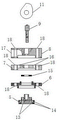
FIG. 1 is a schematic view of an air motor according to the present invention;
FIG. 2 is an exploded view of a portion of the air motor shown in FIG. 1;
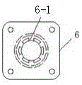
FIG. 3 is a top view of a moving valve cover of the air engine of FIG. 1;
FIG. 4 is a schematic illustration of the air engine-exhaust operating condition of FIG. 1;
FIG. 5 is a schematic structural view of an air compressor;
FIG. 6 is a schematic view of the structure of an air motor system of a motor driven air compressor driven by a breathing air movement
FIG. 7 is a schematic view of an air motor system configured to drive an air compressor, such as a breathing air movement gear;
FIG. 8 is a schematic view of the forward and reverse gearbox of the system of FIG. 7;
FIG. 9 is a side view of a counter-rotating gearbox;
in the figure: 1-an air engine main body, 2-an air cylinder buffer air storage cavity, 3-a piston, 4-an air cylinder, 5-a movable air valve, 6-a movable air valve sleeve, 6-1-an air exhaust port, 7-an air exhaust valve plate, 8-an air exhaust cover, 9-an air valve ejector rod, 10-a camshaft seat, 11-a cam shaft with a cam, 12-a camshaft cover, 13-an air exhaust hole I, 14-a movable air valve sealing ring, 15-a sealing gasket, 16-an air exhaust hole II, 17-an air exhaust hole III, 18-a screw hole, 19-a connecting rod, 20-a crankshaft and 21-an air cylinder buffer air storage cavity air inlet hole;
22-air compressor, 23-screw, 24-screw nut, 25-nut moving frame, 26-air compressor base, 27-piston moving shaft, 28-left cylinder seat frame, 29-right cylinder seat frame, 30-1-first left cylinder piston, 30-2-second left cylinder piston, 30-3-first right cylinder piston, 30-4-second right cylinder piston, 31-1-first left cylinder, 31-2-second left cylinder, 31-3-first right cylinder, 31-4-second right cylinder, 32-1-first left cylinder cover, 32-2-second left cylinder cover, 32-3-first right cylinder cover, 32-4-second right cylinder cover, 33-1-left cylinder air inlet I, 33-2-left cylinder air inlet II, 33-3-right cylinder air inlet I, 33-4-right cylinder air inlet II, 34-1-left cylinder air outlet I, 34-2-left cylinder air outlet II, 34-3-right cylinder air outlet I, 34-4-right cylinder air outlet II;
35-forward and reverse gear box, 36-gear box shell, 37-driving gear shaft, 38-driving gear, 39-driving half-toothed gear, 40-driven gear, 41-driven half-toothed gear, 42-driven gear shaft, 43-transmission gear, 44-transmission gear shaft, 45-output gear, 46-output gear shaft, 47-1-air engine, air compressor and gear set, 47-2-air engine and air compressor, 48-starting air source electric air pump, 49-low pressure air storage tank, 50-air pipe I (low pressure air inlet compressor), 51-air pipe II (high pressure air inlet tank of air compressor), 52-high pressure air storage tank, 53-air pipe III (air inlet tank buffer air storage cavity of high pressure air storage tank), 54-air conveying pipe IV (an air inlet hole of air engine exhaust air into low pressure air storage tank), 55-air conveying pipe V (an air inlet hole of air compressor into low pressure air storage tank), 56-motor, 57-return air storage tank, 58-air conveying pipe VI, 59-air conveying pipe VII, 60-air conveying pipe VIII, 61-air conveying pipe IX and 62-air conveying pipe X.
Detailed Description
The invention is further explained with reference to the drawings and the embodiments.
Examples
Referring to fig. 1 to 4, an air engine includes an air engine body 1, a piston 3, a movable valve 5, a movable valve cover 6, an exhaust valve plate 7, an exhaust cover 8, a valve lift 9, a camshaft base 10, a camshaft with cam 11, a camshaft cover 12, a connecting rod 19, and a crankshaft 20;
an air cylinder buffer air storage cavity 2 and an air cylinder 4 are arranged in the air engine main body 1, the air cylinder 4 is communicated with the air cylinder buffer air storage cavity 2, the piston 3 is sleeved with the air cylinder 4 and is connected with a crankshaft 20 through a connecting rod 19, and an air cylinder buffer air storage cavity air inlet 21 is arranged on the air engine main body 1; an exhaust hole I13 is formed in the movable valve 5, and the movable valve 5 is assembled and connected with the movable valve sleeve 6 through a movable valve sealing ring 14 and is positioned above the cylinder 4; the movable valve sleeve 6 is provided with an exhaust port 6-1 and sleeved with the movable valve 5, and the movable valve sleeve 6 is arranged on the air engine main body 1; an exhaust hole II 16 is formed in the exhaust valve plate 7, the exhaust valve plate 7 is installed on the movable valve sleeve 6, a sealing gasket 15 is arranged between the exhaust valve plate 7 and the movable valve sleeve 6, and the sealing gasket 15 is connected with the movable valve 5; the exhaust cover 8 is provided with an exhaust hole III 17, the exhaust cover 8 is arranged on the exhaust valve plate 7, and the valve ejector rod 9 penetrates through the exhaust cover 8, the exhaust valve plate 7 and the sealing gasket 15 to be connected with the movable valve 5; the exhaust valve comprises a camshaft base 10, a camshaft 11 with a cam, a valve ejector rod 9, a camshaft cover 12, an exhaust valve plate 7, a movable valve sleeve 6 and an exhaust cover 10, wherein the camshaft base 10 is installed on an exhaust cover 8, the camshaft 11 with the cam is installed on the camshaft base 10 and is located above the valve ejector rod 9, the camshaft cover 12 is installed on the camshaft base 10, and the camshaft cover 12, the camshaft base 10, the exhaust cover 8, the exhaust valve plate 7 and the movable valve sleeve 6 are tightly screwed through screw.
In the present embodiment, the cam shaft 11 is connected to an electric motor.
The working process is as follows: compressed air in the high-pressure air storage tank enters the air cylinder buffering air storage cavity 2 through an air delivery pipe, the electric motor drives the cam shaft 11 of the cam to rotate, when the highest point of the cam shaft 11 leaves the valve ejector rod 9, the movable valve 5 moves upwards, and high-pressure air in the air cylinder buffering air storage cavity 2 enters the air cylinder 4 to drive the piston 3 to drive the crankshaft 20 to rotate through the connecting rod 19; when the piston 3 moves to the bottommost end of the cylinder 4, the highest point of the cam shaft 11 contacts the valve ejector rod 9, the valve ejector rod 9 pushes the movable valve 5 to move downwards, the movable valve 5 and the movable valve sealing ring 14 seal the cylinder 4, at the moment, compressed air in the cylinder 4 passes through the exhaust hole 13 on the movable valve 5, passes through the exhaust port 6-1 and the exhaust valve plate 7 and is exhausted from the exhaust hole 17 of the exhaust cover 8, the piston moves upwards, and on the basis, reciprocating circular motion is carried out.
The air inlet of the existing air engine driving piston is controlled by an airflow switch or a valve, and has no discontinuity matched with the circumferential motion of a crankshaft, so that the air engine does not work stably when the pressure of compressed air is high or low and the air inlet of the engine changes along with the pressure.
Referring to fig. 1 to 6, an air engine system using the above-described air engine, which is constructed like a breathing air movement, includes an air engine, an air compressor 22, a motor 56, a low pressure air tank 49 and a high pressure air tank 52;
the air compressor 22 comprises a screw 23, a screw nut 24, a nut moving frame 25, an air compressor base 26, a piston moving shaft 27, a left cylinder base frame 28, a right cylinder base frame 29, left cylinder pistons (a first left cylinder piston 30-1 and a second left cylinder piston 30-2), right cylinder pistons (a first right cylinder piston 30-3 and a second right cylinder piston 30-4), left cylinders (a first left cylinder 31-1 and a second left cylinder 31-2), right cylinders (a first right cylinder 31-3 and a second right cylinder 31-4), left cylinder covers (a first left cylinder cover 32-1 and a second left cylinder cover 32-2) and right cylinder covers (a first right cylinder cover 32-3 and a second right cylinder cover 32-4), wherein the screw 23, the left cylinder base frame 28 and the right cylinder base frame 29 are connected with the air compressor base 26, the screw 23 is matched with a screw nut 24, the screw nut 24 is connected with a nut moving frame 25, the nut moving frame 25 is connected with a piston moving shaft 27, the piston moving shaft 27 is connected with a left cylinder piston and a right cylinder piston, the left cylinder and the left cylinder piston are sleeved with each other, and is connected with a left cylinder cover and a left cylinder seat frame 28, the right cylinder is sleeved with a right cylinder piston, and is connected with a right cylinder cover and a right cylinder seat frame 29, a left cylinder is provided with a left cylinder inlet (a left cylinder inlet I33-1, a left cylinder inlet II 33-2) and a left cylinder exhaust (a left cylinder exhaust I34-1, a left cylinder exhaust II 34-2), the right cylinder is provided with a right cylinder air inlet (a right cylinder air inlet I33-3, a right cylinder air inlet II 33-4) and a right cylinder air outlet (a right cylinder air outlet I34-3 and a right cylinder air outlet II 34-4);
the motor 56 is connected with the screw 23 of the air compressor 22, the exhaust hole of the low-pressure air storage tank 49 is connected with the air inlet of the right cylinder (the air inlet I33-3 of the right cylinder and the air inlet II 33-4 of the right cylinder) of the air compressor main body 22 through an air pipe I50, the right cylinder exhaust port (the right cylinder exhaust port I34-3 and the right cylinder exhaust port II 34-4) of the air compressor main body 22 is connected with a high-pressure air storage tank 52 through an air conveying pipe II 51, the exhaust hole of the high-pressure air storage tank 52 is connected with the air inlet hole of the air engine main body 1 through an air pipe III 53, the exhaust hole of the air engine main body 1 is connected with the air inlet hole of the low-pressure air storage tank 49 through an air conveying pipe IV 54, and the left air cylinder exhaust port (a left air cylinder exhaust port I34-1 and a left air cylinder exhaust port II 34-2) of the air compressor main body 22 is connected with the air inlet hole of the low-pressure air storage tank 49 through an air conveying pipe V55.
Working process; the motor 56 drives the screw rod 23 of the air compressor 22 to move the piston moving shaft 27 to reciprocate to compress air, meanwhile, the exhaust gas of the air engine enters the low-pressure air storage tank 49, the air is sucked from the air inlet of the right air cylinder of the air compressor, compressed and discharged to enter the high-pressure air storage tank 52, the exhaust gas of the high-pressure air storage tank 52 enters the air engine to be supplied, the purpose of recycling the compressed air is achieved, meanwhile, the crankshaft of the air engine drives the generator to generate electricity and convert the electricity into electric energy, and the purpose of mutually circularly converting the electric energy, the air energy and the mechanical.
Referring to fig. 7 to 9, an air engine system using the above-described air engine for making up a motion like breathing air includes an air engine, an air compressor 22, a forward and reverse gear box 35, a starting air source electric air pump 48, a low pressure air tank 49 and a return air tank 57;
the air compressor 22 comprises a screw 23, a screw nut 24, a nut moving frame 25, an air compressor base 26, a piston moving shaft 27, a left cylinder base frame 28, a right cylinder base frame 29, left cylinder pistons (a first left cylinder piston 30-1 and a second left cylinder piston 30-2), right cylinder pistons (a first right cylinder piston 30-3 and a second right cylinder piston 30-4), left cylinders (a first left cylinder 31-1 and a second left cylinder 31-2), right cylinders (a first right cylinder 31-3 and a second right cylinder 31-4), left cylinder covers (a first left cylinder cover 32-1 and a second left cylinder cover 32-2) and right cylinder covers (a first right cylinder cover 32-3 and a second right cylinder cover 32-4), wherein the screw 23, the left cylinder base frame 28 and the right cylinder base frame 29 are connected with the air compressor base 26, the screw 23 is matched with a screw nut 24, the screw nut 24 is connected with a nut moving frame 25, the nut moving frame 25 is connected with a piston moving shaft 27, the piston moving shaft 27 is connected with a left cylinder piston and a right cylinder piston, the left cylinder and the left cylinder piston are sleeved with each other, and is connected with a left cylinder cover and a left cylinder seat frame 28, the right cylinder is sleeved with a right cylinder piston, and is connected with a right cylinder cover and a right cylinder seat frame 29, a left cylinder air inlet (a left cylinder air inlet I33-1, a left cylinder air inlet II 33-2) and a left cylinder air outlet (a left cylinder air outlet I34-1, a left cylinder air outlet II 34-2) are arranged on the left cylinder, the right cylinder is provided with a right cylinder air inlet (a right cylinder air inlet I33-3, a right cylinder air inlet II 33-4) and a right cylinder air outlet (a right cylinder air outlet I34-3 and a right cylinder air outlet II 34-4);
the starting air source electric air pump 48 is connected with the low-pressure air storage tank 49, an exhaust hole of the low-pressure air storage tank 49 is connected with an air inlet 21 of a buffering air storage cavity of an air engine cylinder through an air conveying pipe VI 58, an exhaust hole 17 of an exhaust cover of the air engine is connected with an air inlet of a return air storage tank 57 through an air conveying pipe VII 59, an exhaust hole of the return air storage tank 57 is connected with a right cylinder air inlet (a right cylinder air inlet I33-3 and a right cylinder air inlet II 33-4) of the air compressor 22 through an air conveying pipe VIII 60, a right cylinder exhaust port (a right cylinder exhaust port I34-3 and a right cylinder exhaust port II 34-4) of the air compressor main body 22 is connected with an air inlet of the low-pressure air storage tank 49 through an air conveying pipe IX 61, a left cylinder exhaust port (a left cylinder exhaust port I34-1 and a left cylinder exhaust port II 34, the crankshaft 20 of the air engine is connected with a screw 23 of an air compressor 22 through a forward and reverse rotation gear box 35.
The forward and reverse rotation gearbox 35 comprises a gearbox shell 36, a driving gear shaft 37, a driving gear 38, a driving half-edge gear 39, a driven gear 40, a driven half-edge gear 41, a driven gear shaft 42, a transmission gear 43, a transmission gear shaft 44, an output gear 45 and an output gear shaft 46, wherein the driving gear shaft 37 is connected with the gearbox shell 36, the driving gear 38 and the driving half-edge gear 39, the transmission gear shaft 43 is connected with the gearbox shell 36 and the transmission gear 44, the output gear shaft 46 is connected with the gearbox shell 36 and the output gear 46, the driving gear 38 is meshed with the driven gear 40, the driving half-edge gear 39 and the driven half-edge gear 41 are meshed with the transmission gear 43, and the transmission gear 43 is meshed with the output gear 45.
Working process; the electric energy of the motor is converted into mechanical energy to compress air, the compressed air drives the air engine to be converted into mechanical energy, the left side of a crankshaft of the air engine drives a forward and reverse gear, an output shaft of the forward and reverse gear drives a screw rod of an air compressor to move a piston moving shaft to reciprocate to compress air, meanwhile, the exhaust gas of the air engine enters a return gas storage tank, is sucked into a gas inlet of a right cylinder of the air compressor to be compressed and discharged into a low-pressure gas storage tank, the purpose of recycling the compressed air is achieved, meanwhile, a right transmission generator of the crankshaft of the air engine generates electricity to be converted into electric energy, the mutual cyclic conversion of the electric energy, the air.
The air engine system moving like breathing air has the advantages of stable work doing, simple structure, low production cost, low energy consumption, environmental protection and the like.
The above description is only for the purpose of illustrating the preferred embodiments of the present invention and is not to be construed as limiting the invention, and any modifications, equivalents and the like that are within the spirit and principle of the present invention are included in the present invention.
Claims (8)
1. An air engine, includes air engine main part, piston, its characterized in that: the device is also provided with a movable air valve, a movable air valve sleeve, an exhaust valve plate, an exhaust cover, an air valve ejector rod, a cam shaft seat, a cam shaft with a cam, a cam shaft cover, a connecting rod and a crankshaft;
the air engine main body is internally provided with an air cylinder buffer air storage cavity and an air cylinder, the air cylinder is communicated with the air cylinder buffer air storage cavity, the piston is sleeved with the air cylinder and is connected with the crankshaft through a connecting rod, and the air engine main body is provided with an air inlet hole of the air cylinder buffer air storage cavity; the movable air valve is provided with an exhaust hole I, is assembled and connected with the movable air valve sleeve through a movable air valve sealing ring and is positioned above the air cylinder; the movable valve sleeve is provided with an exhaust port and sleeved with the movable valve, and the movable valve sleeve is arranged on the air engine main body; the exhaust valve plate is provided with an exhaust hole II, the exhaust valve plate is arranged on the movable valve sleeve, a sealing gasket is arranged between the exhaust valve plate and the movable valve sleeve, and the sealing gasket is connected with the movable valve; the exhaust cover is provided with an exhaust hole III, the exhaust cover is arranged on an exhaust valve plate, and the valve ejector rod penetrates through the exhaust cover, the exhaust valve plate and the sealing gasket to be connected with the movable valve; the exhaust valve comprises a camshaft base, a camshaft cover, an exhaust valve plate, a movable valve cover and a connecting piece, wherein the camshaft base is arranged on an exhaust cover, the camshaft with a cam is arranged on the camshaft base and is positioned above a valve ejector rod, the camshaft cover is arranged on the camshaft base, and the camshaft cover, the camshaft base, the exhaust cover, the exhaust valve plate and the movable valve cover are fixedly connected through the connecting piece.
2. The air engine of claim 1, wherein: the camshaft with the cam is connected with the power starting device.
3. The air engine of claim 2, wherein: the power starting device is an electric motor.
4. An air motor system for moving like breathing air using the air motor of claim 1, comprising an air motor, an air compressor, an electric motor, a low pressure air tank and a high pressure air tank;
the air compressor comprises a screw rod, a screw nut, a nut moving frame, an air compressor base, a piston moving shaft, a left air cylinder base frame, a right air cylinder base frame, a left air cylinder piston, a right air cylinder piston, a left air cylinder, a right air cylinder, a left air cylinder cover and a right air cylinder cover, wherein the screw rod, the left air cylinder base frame and the right air cylinder base frame are connected with the air compressor base, the screw rod is matched with the screw nut, the screw nut is connected with the nut moving frame, the nut moving frame is connected with the piston moving shaft, the piston moving shaft is connected with the left air cylinder piston and the right air cylinder piston, the left air cylinder is sleeved with the left air cylinder piston and is connected with the left air cylinder cover and the left air cylinder base frame, the right air cylinder is sleeved with the right air cylinder piston and is connected with the right air cylinder cover and the right air cylinder base frame, a left, A right cylinder exhaust port;
the motor is connected with the lead screw of air compressor machine, the exhaust hole of low pressure gas holder passes through gas-supply pipe I with the right cylinder air inlet of air compressor machine main part and is connected, the right cylinder gas vent of air compressor machine main part passes through gas-supply pipe II with high pressure gas holder and is connected, the exhaust hole of high pressure gas holder passes through gas-supply pipe III with the inlet port of air engine main part and is connected, the exhaust hole of air engine main part passes through gas-supply pipe IV with the inlet port of low pressure gas holder and is connected, the left cylinder gas vent of air compressor machine main part passes through gas-supply pipe V.
5. Air engine system like breathing air movement according to claim 4, characterized in that: the left cylinder seat frame, the right cylinder seat frame, the left cylinder piston, the right cylinder piston, the left cylinder, the right cylinder, the left cylinder cover and the right cylinder cover are more than two groups and are respectively connected with the nut moving frame through piston moving shafts.
6. An air motor system that uses the air motor of claim 1 to create a motion like breathing air, characterized by: the device comprises an air engine, an air compressor, a forward and reverse gear box, a starting air source electric air pump, a low-pressure air storage tank and a return air storage tank;
the air compressor comprises a screw rod, a screw nut, a nut moving frame, an air compressor base, a piston moving shaft, a left air cylinder base frame, a right air cylinder base frame, a left air cylinder piston, a right air cylinder piston, a left air cylinder, a right air cylinder, a left air cylinder cover and a right air cylinder cover, wherein the screw rod, the left air cylinder base frame and the right air cylinder base frame are connected with the air compressor base, the screw rod is matched with the screw nut, the screw nut is connected with the nut moving frame, the nut moving frame is connected with the piston moving shaft, the piston moving shaft is connected with the left air cylinder piston and the right air cylinder piston, the left air cylinder is sleeved with the left air cylinder piston and is connected with the left air cylinder cover and the left air cylinder base frame, the right air cylinder is sleeved with the right air cylinder piston and is connected with the right air cylinder cover and the right air cylinder base frame, a left, A right cylinder exhaust port;
the electronic air pump of start air supply links to each other with the low pressure gas holder, the exhaust hole and the air engine cylinder buffering gas storage chamber inlet port of low pressure gas holder pass through gas-supply pipe VI and are connected, air engine exhaust cover exhaust hole is connected through gas-supply pipe VII with return air gas holder inlet port, return air gas holder exhaust hole is connected through gas-supply pipe VIII with air compressor machine right side cylinder air inlet, the right cylinder gas vent and the low pressure gas holder inlet port of air compressor machine main part pass through gas-supply pipe IX and are connected, the left cylinder gas vent of air compressor machine main part passes through gas-supply pipe X with the inlet port of low pressure gas holder and is connected, air engine's bent axle is connected with the lead screw.
7. Air engine system like breathing air movement according to claim 6, characterized in that: the positive and negative rotation gear box comprises a gear box shell, a driving gear shaft, a driving gear, a driving half-edge gear, a driven half-edge gear, a driven gear shaft, a transmission gear shaft, an output gear and an output gear shaft, wherein the driving gear shaft is connected with the gear box shell, the driving gear and the driving half-edge gear, the transmission gear shaft is connected with the gear box shell and the transmission gear, the output gear shaft is connected with the gear box shell and the output gear, the driving gear is meshed with the driven gear, the driving half-edge gear and the driven half-edge gear are meshed with the transmission gear, and the transmission gear is meshed with the output gear.
8. Air engine system like breathing air movement according to claim 6, characterized in that: the left cylinder seat frame, the right cylinder seat frame, the left cylinder piston, the right cylinder piston, the left cylinder, the right cylinder, the left cylinder cover and the right cylinder cover are more than two groups and are respectively connected with the nut moving frame through piston moving shafts.
Priority Applications (1)
| Application Number | Priority Date | Filing Date | Title |
|---|---|---|---|
| CN202010587204.5A CN111691925B (en) | 2020-06-24 | 2020-06-24 | Air engine |
Applications Claiming Priority (1)
| Application Number | Priority Date | Filing Date | Title |
|---|---|---|---|
| CN202010587204.5A CN111691925B (en) | 2020-06-24 | 2020-06-24 | Air engine |
Publications (2)
| Publication Number | Publication Date |
|---|---|
| CN111691925A true CN111691925A (en) | 2020-09-22 |
| CN111691925B CN111691925B (en) | 2021-11-09 |
Family
ID=72483085
Family Applications (1)
| Application Number | Title | Priority Date | Filing Date |
|---|---|---|---|
| CN202010587204.5A Active CN111691925B (en) | 2020-06-24 | 2020-06-24 | Air engine |
Country Status (1)
| Country | Link |
|---|---|
| CN (1) | CN111691925B (en) |
Cited By (1)
| Publication number | Priority date | Publication date | Assignee | Title |
|---|---|---|---|---|
| CN117052474A (en) * | 2023-10-12 | 2023-11-14 | 张谭伟 | A double crankshaft compressed air engine |
Citations (32)
| Publication number | Priority date | Publication date | Assignee | Title |
|---|---|---|---|---|
| EP0151313A1 (en) * | 1984-01-25 | 1985-08-14 | Pewa Technic Ag | Gas powered engine |
| CN1174937A (en) * | 1996-11-23 | 1998-03-04 | 周可忠 | Air engine |
| US20010032469A1 (en) * | 2000-03-31 | 2001-10-25 | Aisin Seiki Kabushiki Kaisha | Pulse tube refrigerator |
| CA2486227A1 (en) * | 2002-04-22 | 2003-10-30 | Mdi Motor Development International S.A. | Variable flow reducing valve and gradual control valve distribution system for a compressed air injection engine operating on mono or multi energy and other engines or compressors |
| US20030209013A1 (en) * | 2002-05-09 | 2003-11-13 | Yu-Chi Tsai | Piston air engine |
| DE102004014518A1 (en) * | 2004-03-25 | 2005-10-20 | Eduard Menrath | Air control method for a cylinder in a piston engine driven by compressed air and for a piston engine driven by compressed air controls the supply of compressed air |
| US20070101712A1 (en) * | 2003-11-17 | 2007-05-10 | Guy Negre | Engine with an active mono-energy and/or bi-energy chamber with compressed air and/or additional energy and thermodynamic cycle thereof |
| CN101092948A (en) * | 2006-01-24 | 2007-12-26 | 高阳 | Piston type four cycle engine of reciprocating air motor power, electromagnetic repellent force, and inertia force |
| CN101096913A (en) * | 2006-06-26 | 2008-01-02 | 常绪芝 | Hot air engine used in car |
| US20080047265A1 (en) * | 2004-08-06 | 2008-02-28 | Microgen Energy Limited | Linear Free Piston Stirling Machine |
| US20080276615A1 (en) * | 2007-05-11 | 2008-11-13 | The Regents Of The University Of California | Harmonic engine |
| CN101413403A (en) * | 2008-11-05 | 2009-04-22 | 周登荣 | Air power engine assembly |
| CN101435343A (en) * | 2008-12-09 | 2009-05-20 | 南昌航空大学 | Automatic air intake and discharge pneumatic engine |
| CN101526011A (en) * | 2009-04-15 | 2009-09-09 | 武睿 | Atmospheric exhaust variable-cylinder air engine |
| US20100071640A1 (en) * | 2008-09-25 | 2010-03-25 | Rez Mustafa | Internal combustion engine with dual-chamber cylinder |
| EP2450528A1 (en) * | 2009-06-30 | 2012-05-09 | Guangzhou Pengshuo Electromechanical Technology Co., Ltd. | Piston type pneumatic engine |
| CN102817637A (en) * | 2012-08-06 | 2012-12-12 | 北京航空航天大学 | Gas distribution mechanism of pneumatic automobile engine based on sliding valves |
| CN103306727A (en) * | 2012-03-13 | 2013-09-18 | 周登荣 | Gearbox used for V-shaped multi-cylinder aerodynamic engine |
| WO2014026423A1 (en) * | 2012-08-17 | 2014-02-20 | Peng Xuejun | Turbine engine using compressed air as working energy source |
| CN103821578A (en) * | 2014-03-14 | 2014-05-28 | 大连理工大学 | Hydraulic control high-pressure air inlet system of compressed air engine |
| CN103967525A (en) * | 2013-01-30 | 2014-08-06 | 祥天控股(集团)有限公司 | Micro aerodynamic engine |
| EP2772611A1 (en) * | 2011-10-28 | 2014-09-03 | Beijing Xiangtian Huachuang Aerodynamic Force Technology Research Institute Company Limited | Two-stroke air-powered engine assembly |
| CN104100371A (en) * | 2013-04-10 | 2014-10-15 | 张楠希 | Traditional air cylinder piston high-speed rotor engine |
| CN104131842A (en) * | 2013-05-03 | 2014-11-05 | 张楠希 | Air circulating rotor engine |
| CN203962046U (en) * | 2014-07-17 | 2014-11-26 | 襄阳分数线机械设计有限公司 | A kind of piston type air energy motor of overhead camshaft |
| CN203978502U (en) * | 2014-07-26 | 2014-12-03 | 王朋 | Air-powered motor |
| CN104895613A (en) * | 2015-04-03 | 2015-09-09 | 康柱 | Air-powered engine |
| CN205805703U (en) * | 2016-05-11 | 2016-12-14 | 张昭贵 | Hybrid power cylinder and hybrid power engine |
| CN106285784A (en) * | 2016-08-30 | 2017-01-04 | 武汉理工大学 | There is the compressed air engine of energy-storage system |
| US20170211435A1 (en) * | 2014-05-22 | 2017-07-27 | Cyril Negre | Compressed-air engine with an integrated active chamber and with active intake distribution |
| CN109854306A (en) * | 2018-12-27 | 2019-06-07 | 张谭伟 | A kind of assembly of pneumatic circulating air pressure pump and air engine |
| CN110242537A (en) * | 2019-06-27 | 2019-09-17 | 张谭伟 | A kind of feed screw nut's air compressor machine |
-
2020
- 2020-06-24 CN CN202010587204.5A patent/CN111691925B/en active Active
Patent Citations (32)
| Publication number | Priority date | Publication date | Assignee | Title |
|---|---|---|---|---|
| EP0151313A1 (en) * | 1984-01-25 | 1985-08-14 | Pewa Technic Ag | Gas powered engine |
| CN1174937A (en) * | 1996-11-23 | 1998-03-04 | 周可忠 | Air engine |
| US20010032469A1 (en) * | 2000-03-31 | 2001-10-25 | Aisin Seiki Kabushiki Kaisha | Pulse tube refrigerator |
| CA2486227A1 (en) * | 2002-04-22 | 2003-10-30 | Mdi Motor Development International S.A. | Variable flow reducing valve and gradual control valve distribution system for a compressed air injection engine operating on mono or multi energy and other engines or compressors |
| US20030209013A1 (en) * | 2002-05-09 | 2003-11-13 | Yu-Chi Tsai | Piston air engine |
| US20070101712A1 (en) * | 2003-11-17 | 2007-05-10 | Guy Negre | Engine with an active mono-energy and/or bi-energy chamber with compressed air and/or additional energy and thermodynamic cycle thereof |
| DE102004014518A1 (en) * | 2004-03-25 | 2005-10-20 | Eduard Menrath | Air control method for a cylinder in a piston engine driven by compressed air and for a piston engine driven by compressed air controls the supply of compressed air |
| US20080047265A1 (en) * | 2004-08-06 | 2008-02-28 | Microgen Energy Limited | Linear Free Piston Stirling Machine |
| CN101092948A (en) * | 2006-01-24 | 2007-12-26 | 高阳 | Piston type four cycle engine of reciprocating air motor power, electromagnetic repellent force, and inertia force |
| CN101096913A (en) * | 2006-06-26 | 2008-01-02 | 常绪芝 | Hot air engine used in car |
| US20080276615A1 (en) * | 2007-05-11 | 2008-11-13 | The Regents Of The University Of California | Harmonic engine |
| US20100071640A1 (en) * | 2008-09-25 | 2010-03-25 | Rez Mustafa | Internal combustion engine with dual-chamber cylinder |
| CN101413403A (en) * | 2008-11-05 | 2009-04-22 | 周登荣 | Air power engine assembly |
| CN101435343A (en) * | 2008-12-09 | 2009-05-20 | 南昌航空大学 | Automatic air intake and discharge pneumatic engine |
| CN101526011A (en) * | 2009-04-15 | 2009-09-09 | 武睿 | Atmospheric exhaust variable-cylinder air engine |
| EP2450528A1 (en) * | 2009-06-30 | 2012-05-09 | Guangzhou Pengshuo Electromechanical Technology Co., Ltd. | Piston type pneumatic engine |
| EP2772611A1 (en) * | 2011-10-28 | 2014-09-03 | Beijing Xiangtian Huachuang Aerodynamic Force Technology Research Institute Company Limited | Two-stroke air-powered engine assembly |
| CN103306727A (en) * | 2012-03-13 | 2013-09-18 | 周登荣 | Gearbox used for V-shaped multi-cylinder aerodynamic engine |
| CN102817637A (en) * | 2012-08-06 | 2012-12-12 | 北京航空航天大学 | Gas distribution mechanism of pneumatic automobile engine based on sliding valves |
| WO2014026423A1 (en) * | 2012-08-17 | 2014-02-20 | Peng Xuejun | Turbine engine using compressed air as working energy source |
| CN103967525A (en) * | 2013-01-30 | 2014-08-06 | 祥天控股(集团)有限公司 | Micro aerodynamic engine |
| CN104100371A (en) * | 2013-04-10 | 2014-10-15 | 张楠希 | Traditional air cylinder piston high-speed rotor engine |
| CN104131842A (en) * | 2013-05-03 | 2014-11-05 | 张楠希 | Air circulating rotor engine |
| CN103821578A (en) * | 2014-03-14 | 2014-05-28 | 大连理工大学 | Hydraulic control high-pressure air inlet system of compressed air engine |
| US20170211435A1 (en) * | 2014-05-22 | 2017-07-27 | Cyril Negre | Compressed-air engine with an integrated active chamber and with active intake distribution |
| CN203962046U (en) * | 2014-07-17 | 2014-11-26 | 襄阳分数线机械设计有限公司 | A kind of piston type air energy motor of overhead camshaft |
| CN203978502U (en) * | 2014-07-26 | 2014-12-03 | 王朋 | Air-powered motor |
| CN104895613A (en) * | 2015-04-03 | 2015-09-09 | 康柱 | Air-powered engine |
| CN205805703U (en) * | 2016-05-11 | 2016-12-14 | 张昭贵 | Hybrid power cylinder and hybrid power engine |
| CN106285784A (en) * | 2016-08-30 | 2017-01-04 | 武汉理工大学 | There is the compressed air engine of energy-storage system |
| CN109854306A (en) * | 2018-12-27 | 2019-06-07 | 张谭伟 | A kind of assembly of pneumatic circulating air pressure pump and air engine |
| CN110242537A (en) * | 2019-06-27 | 2019-09-17 | 张谭伟 | A kind of feed screw nut's air compressor machine |
Non-Patent Citations (2)
| Title |
|---|
| 孙珺朋等: "气动发动机工作过程建模及性能分析", 《液压与气动》 * |
| 高新等: "新型空气动力发动机进气门的研究", 《内燃机与动力装置》 * |
Cited By (2)
| Publication number | Priority date | Publication date | Assignee | Title |
|---|---|---|---|---|
| CN117052474A (en) * | 2023-10-12 | 2023-11-14 | 张谭伟 | A double crankshaft compressed air engine |
| CN117052474B (en) * | 2023-10-12 | 2025-10-31 | 张谭伟 | Double-crankshaft compressed air engine |
Also Published As
| Publication number | Publication date |
|---|---|
| CN111691925B (en) | 2021-11-09 |
Similar Documents
| Publication | Publication Date | Title |
|---|---|---|
| CN103069111B (en) | Efficient motors powered by compressed air or other compressible gases | |
| CN111691925A (en) | Air engine and air engine system like breathing air movement | |
| CN103758637B (en) | A kind of self balancing high speed free-piston generator | |
| CN209818241U (en) | Magnetic reciprocating piston compressor | |
| CN105134567A (en) | Horizontally-opposite diaphragm type electric vacuum pump | |
| CN102287293A (en) | Engine with closed cylinder port | |
| CN112377384A (en) | Controllable two-stage compression air compressor | |
| RU2576722C1 (en) | Method of charging hydraulic accumulator of drive system of distribution valve internal combustion engine using piezoelectric pump | |
| CN214366585U (en) | Hydraulic air compressor | |
| CN214887544U (en) | Gas supercharging device | |
| CN218407698U (en) | Six-cylinder plunger pump | |
| US20250122804A1 (en) | Vacuum Engine | |
| CN201326590Y (en) | Pneumatic reciprocating supercharger | |
| CN2310861Y (en) | Spiral rotor engine | |
| CN104131842A (en) | Air circulating rotor engine | |
| CN209810478U (en) | Hydraulic paint spraying pump | |
| US20200224535A1 (en) | Pressure controlled hydraulic engine | |
| CN107218119B (en) | Single-supercharger double-cylinder engine | |
| CN2414217Y (en) | Bidirectional infaltor | |
| CN109356810A (en) | A cam type multi-stage compression miniature high pressure air pump | |
| CN219587725U (en) | Miniature piston type oil-free compressor for oxygen production | |
| CN215521171U (en) | Single-phase variable frequency air compressor | |
| HK40113431A (en) | Vacuum engine | |
| CN218717306U (en) | Double-stage compression reciprocating vacuum pump | |
| CN203978502U (en) | Air-powered motor |
Legal Events
| Date | Code | Title | Description |
|---|---|---|---|
| PB01 | Publication | ||
| PB01 | Publication | ||
| SE01 | Entry into force of request for substantive examination | ||
| SE01 | Entry into force of request for substantive examination | ||
| GR01 | Patent grant | ||
| GR01 | Patent grant |