CN115727770A - Speckle shearing interference-based method for measuring out-of-plane displacement of curved surface object - Google Patents
Speckle shearing interference-based method for measuring out-of-plane displacement of curved surface object Download PDFInfo
- Publication number
- CN115727770A CN115727770A CN202211454063.5A CN202211454063A CN115727770A CN 115727770 A CN115727770 A CN 115727770A CN 202211454063 A CN202211454063 A CN 202211454063A CN 115727770 A CN115727770 A CN 115727770A
- Authority
- CN
- China
- Prior art keywords
- phase
- speckle
- plane displacement
- measured
- ccd camera
- Prior art date
- Legal status (The legal status is an assumption and is not a legal conclusion. Google has not performed a legal analysis and makes no representation as to the accuracy of the status listed.)
- Granted
Links
Images


Landscapes
- Length Measuring Devices By Optical Means (AREA)
Abstract
本发明涉及一种基于散斑剪切干涉的计量曲面物体离面位移方法,步骤包括:1、获被测物调制后的正弦条纹图并进行灰度处理;2、得到绝对相位信息,获取物体相对相机的三维坐标,获取物体相对相机的三维坐标;3、计算出被测物表面法向量相对CCD相机光轴的夹角


The invention relates to a method for measuring the out-of-plane displacement of a curved surface object based on speckle shear interference. Relative to the three-dimensional coordinates of the camera, obtain the three-dimensional coordinates of the object relative to the camera; 3. Calculate the angle between the surface normal vector of the measured object and the optical axis of the CCD camera
Description
技术领域technical field
本发明设计光学测量检测领域,具体涉及一种基于散斑剪切干涉的计量曲面物体离面位移方法。The invention relates to the field of optical measurement and detection, and specifically relates to a method for measuring the out-of-plane displacement of a curved surface object based on speckle shear interference.
背景技术Background technique
激光散斑剪切干涉技术作为光测力学技术,具有高精度、非接触、全场、实时测量等特点,其优异的抗震性能使其广泛应用在位移测量、应变测量、震动测量、变形测量、温度测量以及工程材料的内部缺陷检测等领域,利用激光散斑剪切技术测量因内部缺陷引起的面外变形量来间接获取缺陷属性是对材料性能判断的方法之一。Laser speckle shearing interferometry technology, as a photomechanical technology, has the characteristics of high precision, non-contact, full-field, real-time measurement, etc. Its excellent seismic performance makes it widely used in displacement measurement, strain measurement, vibration measurement, deformation measurement, In the fields of temperature measurement and internal defect detection of engineering materials, using laser speckle shearing technology to measure the out-of-plane deformation caused by internal defects to indirectly obtain defect attributes is one of the methods for judging material properties.
激光散斑剪切干涉技术通过采集被测物形变前后的散斑图做差处理得到离面位移,该离面位移是沿相机光轴方向,对于曲面(斜面)物体的离面位移测量,被测物体每点的变形方向不一定平行于光轴,所测得的离面位移并不是曲面每点实际的变形量。上海大学李晓东等人通过构建三种波长不同的激光测量光路,使用一台CCD彩色相机一次记录三种光路获得的散斑干涉图像来测量物体的三维变形,但该方法光路复杂,同时需要多种激光光源,操作较为繁琐;山东师范大学孙勇明等人将数字散斑相关法和电子散斑干涉术结合在一起测量物体的三维变形,该方法只能测量平面物体的三维变形;上海交通大学李鹏飞等人,利用激光散斑偏转法求取曲面物体的三维形貌,并结合曲面变形前后的散斑图获得离面形变信息,但是该方法需要高精度的光源偏转仪器,抗干扰性能较差。The laser speckle shearing interference technology obtains the out-of-plane displacement by collecting the speckle images before and after the deformation of the measured object, and the out-of-plane displacement is along the optical axis of the camera. The deformation direction of each point of the measured object is not necessarily parallel to the optical axis, and the measured out-of-plane displacement is not the actual deformation of each point on the surface. Li Xiaodong of Shanghai University and others built three laser measurement optical paths with different wavelengths, and used a CCD color camera to record the speckle interference images obtained by the three optical paths at one time to measure the three-dimensional deformation of the object. Laser light source, the operation is relatively cumbersome; Sun Yongming of Shandong Normal University and others combined digital speckle correlation method and electronic speckle interferometry to measure the three-dimensional deformation of objects. This method can only measure three-dimensional deformation of planar objects; Li Pengfei of Shanghai Jiaotong University et al. used the laser speckle deflection method to obtain the three-dimensional shape of the curved surface object, and combined the speckle images before and after the surface deformation to obtain the out-of-plane deformation information. However, this method requires a high-precision light source deflection instrument and has poor anti-interference performance.
因此,提出一种通过抗干扰性能强的三维形貌和离面形变的组合测量,得到对曲面、斜面的面外形变的计量方法具有十分重要的意义。Therefore, it is of great significance to propose a combined measurement of three-dimensional shape and out-of-plane deformation with strong anti-interference performance to obtain the measurement method for the surface deformation of curved surfaces and inclined surfaces.
发明内容Contents of the invention
针对上述现有问题,本发明提供了一种基于散斑剪切干涉的计量曲面物体离面位移方法,采用剪切散斑干涉与数字条纹投影相结合,以检测出曲面(斜面)物体内部缺陷的同时,并能获取其离面位移信息用于分析其缺陷属性。In view of the above existing problems, the present invention provides a method for measuring the out-of-plane displacement of curved surface objects based on speckle shear interference, which uses the combination of shear speckle interference and digital fringe projection to detect internal defects of curved (slope) objects At the same time, its out-of-plane displacement information can be obtained to analyze its defect properties.
为了实现上述目的,本发明采用的技术方案为:In order to achieve the above object, the technical scheme adopted in the present invention is:
一种基于散斑剪切干涉的计量曲面物体离面位移方法,包括如下步骤:A method for measuring the out-of-plane displacement of a curved surface object based on speckle shear interference, comprising the following steps:
S1、投影仪投出正弦条纹到被测物表面,由CCD相机采集受被测物调制后的正弦条纹图并进行灰度处理;S1. The projector casts sinusoidal fringes to the surface of the measured object, and the CCD camera collects the sinusoidal fringe pattern modulated by the measured object and performs grayscale processing;
S2、利用相移法对CCD相机采集的受调制的投影条纹图像提取包裹相位,结合多频外插法进行解包裹计算,得到绝对相位信息,获取物体相对相机的三维坐标,结合相机与标定的投影系统参数求取物体相对相机的三维坐标;S2. Use the phase shift method to extract the wrapped phase from the modulated projected fringe image collected by the CCD camera, combine the multi-frequency extrapolation method to perform unwrapped calculations, obtain absolute phase information, and obtain the three-dimensional coordinates of the object relative to the camera. Combine the camera with the calibrated Projection system parameters to obtain the three-dimensional coordinates of the object relative to the camera;
S3、利用PCL(Point Cloud Learning)对重建的点云数据集中的三维模型进行法向量估计,并计算出被测物表面法向量相对CCD相机光轴的夹角![]()
![]()
S4、激光器投射激光到被测物表面,通过对被测物施加外部载荷,由CCD相机分别采集被测物表面变形前后的散斑包裹相位图并进行灰度处理和滤波处理;S4. The laser projects laser light onto the surface of the measured object, and by applying an external load to the measured object, the CCD camera collects the speckle wrapping phase images before and after the surface deformation of the measured object, and performs grayscale processing and filtering processing;
S5、利用相移法对CCD相机采集的散斑包裹相位图提取相位,并利用最小二乘解包裹算法对散斑包裹相位图进行相位展开,获得解包后相位分布信息,代入波长、剪切量等参数计算得到所测得的表面离面位移信息(即光程差![]()
![]()
S6、建立激光散斑所测的离面位移测量值(即光程差![]()
![]()
![]()
![]()
S7、根据S6中的几何关系,利用被测物体表面法向量相对CCD相机光轴的夹角![]()

![]()
作为优选的技术方案:As a preferred technical solution:
如上所述的一种基于散斑剪切干涉的计量曲面物体离面位移方法,在步骤S2中,求解绝对相位信息的过程如下:As mentioned above, a method for measuring the out-of-plane displacement of a curved surface object based on speckle shear interference, in step S2, the process of solving the absolute phase information is as follows:
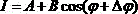
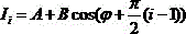
相机采集的相位条纹图的数学表达式为:The mathematical expression of the phase fringe pattern collected by the camera is:

式中,![]()


![]()
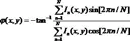
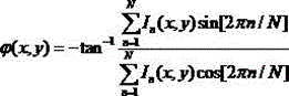
使用相移法求取相位

利用多频外插方法对其相位展开得到绝对相位

式中:

![]()
![]()
![]()
![]()
![]()
![]()
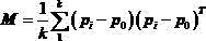
如上所述的一种基于散斑剪切干涉的计量曲面物体离面位移方法,在步骤S3中,对点云数据集进行法向量估计,基于局部平面拟合,创建任一点临近元素的协方差矩阵,求其最小特征值对应的特征向量即为该局部平面法向量![]()
![]()
![]()
![]()
![]()
![]()


式中,![]()
![]()
![]()

![]()


![]()
![]()
![]()
![]()
如上所述的一种基于散斑剪切干涉的计量曲面物体离面位移方法,在步骤S3中,计算被测物表面法向量相对CCD相机光轴的夹角![]()
![]()

式中,![]()
![]()
![]()
![]()
如上所述的一种基于散斑剪切干涉的计量曲面物体离面位移方法,在步骤S5中,通过对散斑包裹相位图进行解包裹计算,得到相位分布信息

![]()
![]()

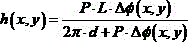
对其积分求解离面位移即光程差![]()
![]()
式中,![]()
![]()
![]()
![]()
![]()
![]()
![]()
![]()
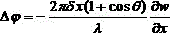
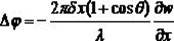
如上所述的一种基于散斑剪切干涉的计量曲面物体离面位移方法,在步骤S6中,激光剪切散斑法测量离面位移信息是将变化前后的相位信息进行相减,得到光轴方向的离面位移信息(即光程差),而物体发生微小离面形变时其方向是沿表面法向量方向,故所测得光程差![]()
![]()
![]()
![]()

如上所述的一种基于散斑剪切干涉的计量曲面物体离面位移方法,在步骤S5中,对散斑包裹相位图进行解包裹计算的过程为:As mentioned above, a method for measuring the out-of-plane displacement of a curved surface object based on speckle shear interference, in step S5, the process of unwrapping and calculating the speckle wrapping phase map is as follows:
变形前的散斑图的光强表达式为

变形后的光强表达式![]()
![]()
将变形前后的条纹图进行相减得到四幅相位包裹图![]()
![]()

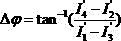
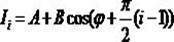
根据四部相移原理,得到变形前后相位变化量:According to the four-part phase shift principle, the phase change before and after deformation is obtained:

需要对其进行解包裹处理得到展开相位图,得到相位分布信息

![]()
![]()

对其积分求解离面位移即光程差![]()
![]()
如上所述的一种基于散斑剪切干涉的计量曲面物体离面位移方法,在步骤S1和S4中,均由同一CCD相机(或光轴平行的两组CCD相机)分别获取被调制的正弦条纹图和散斑包裹相位图,投影仪投出正弦条纹到被测物体表面,光路经由透镜、剪切干涉系统被CCD相机采集,此时剪切干涉系统未处于干涉状态,计算机模块处理得到被测物的三维信息,激光发生器发出的激光阵列经扩束装置后照射在被测物表面,光路由剪切干涉系统分为两束光在空间上形成干涉,由CCD相机采集到散斑包裹相位图。As mentioned above, a method for measuring the out-of-plane displacement of a curved surface object based on speckle shearing interference, in steps S1 and S4, the same CCD camera (or two groups of CCD cameras with parallel optical axes) respectively acquires the modulated sinusoidal The fringe pattern and the speckle wrapped phase pattern, the projector casts sinusoidal fringes to the surface of the measured object, the optical path is collected by the CCD camera through the lens and the shearing interference system. At this time, the shearing interference system is not in the interference state, and the computer module processes it For the three-dimensional information of the measured object, the laser array emitted by the laser generator is irradiated on the surface of the measured object after passing through the beam expander. phase diagram.
本发明还提供一种用于实现上述方法的复用光路系统,如图2所示,所述系统包括扩束镜、投影仪、剪切干涉仪、CCD相机、激光器发生器、计算机模块、反光镜、调节镜、相移器,所述计算机能够控制投影仪和激光器发生器向被测物体表面投影相移编码条纹和激光;所述CCD相机用于捕获被测物表面放射形成的图像,发送给所述计算机生成调制图片组并排序,所述计算机还用于对所述的调制图像进行相位展开,实现对被测物体表面的点云数据重建和被测物表面的离面变形重构,利用点云数据获取被测物表面法向量与光轴的夹角来对离面位移值进行修正。The present invention also provides a multiplexing optical path system for realizing the above method, as shown in Figure 2, the system includes a beam expander, a projector, a shear interferometer, a CCD camera, a laser generator, a computer module, a reflective Mirror, adjusting mirror, phase shifter, the computer can control the projector and the laser generator to project phase-shift coded stripes and laser light on the surface of the measured object; the CCD camera is used to capture the image formed by radiation on the surface of the measured generating and sorting the modulated picture group for the computer, and the computer is also used to phase unwrap the modulated images to realize point cloud data reconstruction of the surface of the measured object and out-of-plane deformation reconstruction of the surface of the measured object, The angle between the surface normal vector of the measured object and the optical axis is obtained by using the point cloud data to correct the out-of-plane displacement value.
与现有技术相比,本发明的有益效果为:Compared with prior art, the beneficial effect of the present invention is:
本发明通过结合面结构光的三维测量和剪切散斑干涉的离面位移测量技术,控制调节镜来实现面结构光与剪切散斑系统的切换,能够实现对三维形貌和离面形变的组合测量,将三维形貌的法向量信息引入离面位移的测量中,实现测量曲面物体的离面位移信息,本发明具有结构简单、能够实现快速测量、抗干扰能力强,能够实现全场、非接触测量。The present invention combines the three-dimensional measurement of surface structured light and the out-of-plane displacement measurement technology of shear speckle interference, and controls the adjustment mirror to realize the switching between surface structured light and shear speckle system, which can realize the three-dimensional shape and out-of-plane deformation The combined measurement of the three-dimensional shape normal vector information is introduced into the measurement of the out-of-plane displacement to realize the measurement of the out-of-plane displacement information of the curved surface object. The invention has the advantages of simple structure, fast measurement, strong anti-interference ability, and full field , Non-contact measurement.
附图说明Description of drawings
图1为本发明的方法流程示意图;Fig. 1 is a schematic flow chart of the method of the present invention;
图2为本发明的离面位移测量方法中的装置及光路系统示意图;Fig. 2 is a schematic diagram of the device and the optical path system in the out-of-plane displacement measuring method of the present invention;
图3为被测物体变形时离面位移与CCD相机所测离面位移的几何关系示意图;Fig. 3 is a schematic diagram of the geometric relationship between the out-of-plane displacement and the out-of-plane displacement measured by the CCD camera when the measured object is deformed;
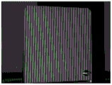
图4为CCD相机采集的条纹光栅图;Fig. 4 is the fringe raster image that CCD camera collects;
图5为重建被测物体的三维点云图;Figure 5 is a three-dimensional point cloud image of the reconstructed object to be measured;
图6为加载变形的散斑包裹相位图;Figure 6 is the speckle wrapping phase diagram of loading deformation;
图7为对散斑包裹相位图解包裹得到的相位图;Fig. 7 is the phase diagram obtained by wrapping the speckle wrapping phase diagram;
图8为激光散斑测得的离面位移信息;Figure 8 shows the out-of-plane displacement information measured by laser speckle;
图9为修正后的离面位移信息;Figure 9 shows the corrected out-of-plane displacement information;
图中:1-激光发生器,2-扩束镜,3-被测物表面,4-投影仪,5-计算机模块,6-CCD相机,7-剪切干涉仪,8-反光镜,9-调节镜,10-相移器。In the figure: 1-laser generator, 2-beam expander, 3-surface of object to be measured, 4-projector, 5-computer module, 6-CCD camera, 7-shearing interferometer, 8-mirror, 9 - adjustment mirror, 10 - phase shifter.
具体实施方式Detailed ways
下面结合具体实施方式,进一步阐述本发明。应理解,这些实施例仅用于说明本发明而不用于限制本发明的范围。此外应理解,在阅读了本发明讲授的内容之后,本领域技术人员可以对本发明作各种改动或修改,这些等价形式同样落于本申请所附权利要求书所限定的范围。The present invention will be further described below in combination with specific embodiments. It should be understood that these examples are only used to illustrate the present invention and are not intended to limit the scope of the present invention. In addition, it should be understood that after reading the teachings of the present invention, those skilled in the art can make various changes or modifications to the present invention, and these equivalent forms also fall within the scope defined by the appended claims of the present application.
一种基于散斑剪切干涉的计量曲面物体离面位移方法,如图1所示,步骤如下:A method of measuring the out-of-plane displacement of a curved surface object based on speckle shear interference, as shown in Figure 1, the steps are as follows:
S1、投影仪4投影光栅条纹到被测物体3上,调节调节镜9使剪切干涉仪7不处于干涉状态,CCD相机6采集受被测物调制后的正弦条纹图并进行灰度处理;S1. The
S2、计算机模块5通过相移法对CCD相机采集的受调制的投影条纹图像提取包裹相位,结合多频外插法进行解包裹计算,得到绝对相位信息,计算机模块5结合相机与标定的投影系统参数求取物体相对相机的三维坐标;S2. The
其中,求解绝对相位信息的过程如下:Among them, the process of solving the absolute phase information is as follows:
相机采集的相位条纹图的数学表达式为:The mathematical expression of the phase fringe pattern collected by the camera is:

式中,![]()


![]()
使用相移法求取相位
利用多频外插方法对其相位展开得到绝对相位
式中:

![]()
![]()
![]()
![]()
![]()
![]()
S3、利用PCL(Point Cloud Learning)对重建的点云数据集中的三维模型进行法向量估计,并计算出被测物表面法向量相对CCD相机光轴的夹角![]()
![]()
其中,法向量估计方法为:对点云数据集进行法向量估计,基于局部平面拟合,创建任一点临近元素的协方差矩阵,求其最小特征值对应的特征向量即为该局部平面法向量![]()
![]()
![]()
![]()
![]()
![]()
式中,![]()
![]()
![]()

![]()


![]()
![]()
![]()
![]()
计算被测物表面法向量相对CCD相机光轴的夹角![]()
![]()

式中,![]()
![]()
![]()
![]()
S4、激光发生器1投射激光到被测物表面3,通过对被测物施加外部载荷,由CCD相机分别采集被测物表面变形前后的散斑包裹相位图并进行灰度处理和滤波处理;S4. The
S5、计算机模块5利用相移法对CCD相机采集的散斑包裹相位图提取相位,并利用最小二乘解包裹算法对散斑包裹相位图进行相位展开,获得解包后相位分布信息,代入波长、剪切量等参数计算得到所测得的表面离面位移信息(即光程差![]()
![]()
其中,通过对散斑包裹相位图进行解包裹计算,Among them, by unwrapping the speckle wrapped phase map,
对散斑包裹相位图进行解包裹计算的过程为:The process of unwrapping the speckle wrapping phase map is as follows:
变形前的散斑图的光强表达式为
变形后的光强表达式![]()
![]()

将变形前后的条纹图进行相减得到四幅相位包裹图![]()
![]()

根据四部相移原理,得到变形前后相位变化量:According to the four-part phase shift principle, the phase change before and after deformation is obtained:
需要对其进行解包裹处理得到展开相位图,得到相位分布信息

![]()
![]()
对其积分求解离面位移即光程差![]()
![]()
式中,![]()
![]()
![]()
![]()
![]()
![]()
![]()
![]()
S6、建立激光散斑所测的离面位移测量值(即光程差![]()
![]()
![]()
![]()
其中,激光剪切散斑法测量离面位移信息是将变化前后的相位信息进行相减,得到光轴方向的离面位移信息(即光程差),而物体发生微小离面形变时其方向是沿表面法向量方向,故所测得光程差![]()
![]()
![]()
![]()

S7、根据S6中的几何关系,利用被测物体表面法向量相对CCD相机光轴的夹角![]()

![]()
在步骤S1和S4,中均由同一CCD相机(或光轴平行的两组CCD相机)分别获取被调制的正弦条纹图和散斑包裹相位图,投影仪投出正弦条纹到被测物体表面,光路经由透镜、剪切干涉系统被CCD相机采集,此时剪切干涉系统未处于干涉状态,计算机模块处理得到被测物的三维信息,激光发生器发出的激光阵列经扩束装置后照射在被测物表面,光路由剪切干涉系统分为两束光在空间上形成干涉,由CCD相机采集到散斑包裹相位图。In steps S1 and S4, the same CCD camera (or two sets of CCD cameras whose optical axes are parallel) obtains the modulated sinusoidal fringe pattern and the speckle wrapping phase pattern respectively, and the projector projects the sinusoidal fringe pattern onto the surface of the measured object. The optical path is collected by the CCD camera through the lens and the shearing interference system. At this time, the shearing interference system is not in the interference state. The computer module processes and obtains the three-dimensional information of the measured object. On the surface of the object to be measured, the light is divided into two beams by the shearing interference system to form interference in space, and the speckle wrapping phase map is collected by the CCD camera.
虽然本发明所揭露的实施方式如上,但所述的内容只是为了便于理解本发明而采用的实施方式,并非用以限定本发明。任何本发明所属技术领域内的技术人员,在不脱离本发明所揭露的精神和范围的前提下,可以在实施的形式及细节上作任何的修改与变化,但本发明的专利保护范围,仍须以所附的权利要求书所界定的范围为准。Although the embodiments disclosed in the present invention are as above, the described content is only an embodiment adopted for the convenience of understanding the present invention, and is not intended to limit the present invention. Anyone skilled in the technical field to which the present invention belongs can make any modifications and changes in the form and details of the implementation without departing from the spirit and scope disclosed in the present invention, but the patent protection scope of the present invention remains the same. The scope defined by the appended claims shall prevail.
Claims (8)


Priority Applications (1)
| Application Number | Priority Date | Filing Date | Title |
|---|---|---|---|
| CN202211454063.5A CN115727770B (en) | 2022-11-21 | 2022-11-21 | A method for measuring off-plane displacement of curved surface objects based on speckle shearing interferometry |
Applications Claiming Priority (1)
| Application Number | Priority Date | Filing Date | Title |
|---|---|---|---|
| CN202211454063.5A CN115727770B (en) | 2022-11-21 | 2022-11-21 | A method for measuring off-plane displacement of curved surface objects based on speckle shearing interferometry |
Publications (2)
| Publication Number | Publication Date |
|---|---|
| CN115727770A true CN115727770A (en) | 2023-03-03 |
| CN115727770B CN115727770B (en) | 2025-10-14 |
Family
ID=85296915
Family Applications (1)
| Application Number | Title | Priority Date | Filing Date |
|---|---|---|---|
| CN202211454063.5A Active CN115727770B (en) | 2022-11-21 | 2022-11-21 | A method for measuring off-plane displacement of curved surface objects based on speckle shearing interferometry |
Country Status (1)
| Country | Link |
|---|---|
| CN (1) | CN115727770B (en) |
Cited By (4)
| Publication number | Priority date | Publication date | Assignee | Title |
|---|---|---|---|---|
| CN116429680A (en) * | 2023-03-31 | 2023-07-14 | 北京京仪自动化装备技术股份有限公司 | Adhesion measurement system, method and electronic device |
| CN120160551A (en) * | 2025-02-20 | 2025-06-17 | 华中科技大学 | A method and system for detecting warpage of electronic packaging based on background schlieren |
| CN120871411A (en) * | 2025-09-22 | 2025-10-31 | 苏州大学 | Interference fringe generating element, generating device and defect detecting method |
| CN121409130A (en) * | 2025-12-26 | 2026-01-27 | 深圳北理莫斯科大学 | Deformation measurement methods, devices and electronic equipment |
Citations (5)
| Publication number | Priority date | Publication date | Assignee | Title |
|---|---|---|---|---|
| JP2003139515A (en) * | 2001-11-02 | 2003-05-14 | Fukuoka Prefecture | Method for measuring absolute value of deformation quantity using speckle |
| CN1916563A (en) * | 2005-08-19 | 2007-02-21 | 韩国轮胎株式会社 | Tyre touchdown shape measuring device using laser disperse spot shearing interference method |
| CN106226313A (en) * | 2016-07-01 | 2016-12-14 | 华南理工大学 | A kind of depth of defect detection method interfered based on speckle-shearing |
| CN108106556A (en) * | 2018-02-02 | 2018-06-01 | 上海交通大学 | Based on the curved face object of digital speckle interference from face distortion measurement method and device |
| CN114527129A (en) * | 2021-12-10 | 2022-05-24 | 桂林电子科技大学 | Small workpiece internal defect detection device and method based on shearing speckle interference |
-
2022
- 2022-11-21 CN CN202211454063.5A patent/CN115727770B/en active Active
Patent Citations (5)
| Publication number | Priority date | Publication date | Assignee | Title |
|---|---|---|---|---|
| JP2003139515A (en) * | 2001-11-02 | 2003-05-14 | Fukuoka Prefecture | Method for measuring absolute value of deformation quantity using speckle |
| CN1916563A (en) * | 2005-08-19 | 2007-02-21 | 韩国轮胎株式会社 | Tyre touchdown shape measuring device using laser disperse spot shearing interference method |
| CN106226313A (en) * | 2016-07-01 | 2016-12-14 | 华南理工大学 | A kind of depth of defect detection method interfered based on speckle-shearing |
| CN108106556A (en) * | 2018-02-02 | 2018-06-01 | 上海交通大学 | Based on the curved face object of digital speckle interference from face distortion measurement method and device |
| CN114527129A (en) * | 2021-12-10 | 2022-05-24 | 桂林电子科技大学 | Small workpiece internal defect detection device and method based on shearing speckle interference |
Cited By (6)
| Publication number | Priority date | Publication date | Assignee | Title |
|---|---|---|---|---|
| CN116429680A (en) * | 2023-03-31 | 2023-07-14 | 北京京仪自动化装备技术股份有限公司 | Adhesion measurement system, method and electronic device |
| CN116429680B (en) * | 2023-03-31 | 2026-03-27 | 北京京仪自动化装备技术股份有限公司 | Adhesion force measurement system, method and electronic equipment |
| CN120160551A (en) * | 2025-02-20 | 2025-06-17 | 华中科技大学 | A method and system for detecting warpage of electronic packaging based on background schlieren |
| CN120871411A (en) * | 2025-09-22 | 2025-10-31 | 苏州大学 | Interference fringe generating element, generating device and defect detecting method |
| CN121409130A (en) * | 2025-12-26 | 2026-01-27 | 深圳北理莫斯科大学 | Deformation measurement methods, devices and electronic equipment |
| CN121409130B (en) * | 2025-12-26 | 2026-04-03 | 深圳北理莫斯科大学 | Deformation measurement method and device and electronic equipment |
Also Published As
| Publication number | Publication date |
|---|---|
| CN115727770B (en) | 2025-10-14 |
Similar Documents
| Publication | Publication Date | Title |
|---|---|---|
| CN115727770A (en) | Speckle shearing interference-based method for measuring out-of-plane displacement of curved surface object | |
| CN113237435B (en) | High-light-reflection surface three-dimensional vision measurement system and method | |
| Quan et al. | Shape measurement of small objects using LCD fringe projection with phase shifting | |
| CN100520285C (en) | Vision measuring method for projecting multiple frequency grating object surface tri-dimensional profile | |
| CN105783775B (en) | A kind of minute surface and class minute surface object surface appearance measuring device and method | |
| CN102589416B (en) | Wavelength scanning interferometer and method for aspheric measurement | |
| CN111307063B (en) | A Method to Eliminate Symbol Ambiguity in Single-frame Interference Fringe Wavefront Restoration | |
| CN106767427B (en) | The method and system of object acoplanarity displacement are measured using vortex optical arrays Strange properties | |
| CN106840027A (en) | The astigmatic compensation type interference checking device and detection method of freeform optics surface | |
| CN108955575B (en) | A method of corrugated is accurately restored based on single width interference fringe | |
| CN103727891A (en) | Synchronous three-dimensional speckle interferometric measurement system and method | |
| CN109780992A (en) | Interferometer measuration system error calibrating method based on the processing of optical flat stripe pattern | |
| CN106197322A (en) | A kind of area-structure light three-dimension measuring system | |
| CN101915559A (en) | Method and system for measuring three-dimensional surface shape of object by using electronic speckle phase shift technology | |
| CN104279981A (en) | Mirror surface/mirror-surface-like object absolute surface shape measuring method and device based on stripe reflection | |
| CN111815697B (en) | A dynamic three-dimensional measurement method for thermal deformation | |
| CN115218810A (en) | Single-camera three-dimensional deformation measurement system and method capable of resisting interference of strong light and strong heat radiation | |
| Guan et al. | An improved geometrical calibration method for stereo deflectometry by using speckle pattern | |
| CN111412850A (en) | High-temperature three-dimensional digital image correlation measurement system and method based on single camera | |
| CN113946117A (en) | Device, method and medium for measuring three-dimensional displacement in scattered light field holographic range | |
| CN115077390A (en) | Large-range picometer displacement measurement system and method based on dual-wavelength vortex optical rotation self-conjugate interference | |
| CN116147518B (en) | Full-field dynamic three-dimensional deformation measurement method and system based on polarization multiplexing | |
| CN112268520A (en) | A non-contact flexible measurement method of gear tooth surface shape error | |
| CN112268521B (en) | Variable-angle synchronous phase shift interferometry method for gear tooth surface shape error | |
| CN117848237B (en) | A three-dimensional surface topography measurement and calculation method based on ellipse fitting |
Legal Events
| Date | Code | Title | Description |
|---|---|---|---|
| PB01 | Publication | ||
| PB01 | Publication | ||
| SE01 | Entry into force of request for substantive examination | ||
| SE01 | Entry into force of request for substantive examination | ||
| GR01 | Patent grant | ||
| GR01 | Patent grant |