EP0000717B1 - Dispositif de fixation pour cloisons - Google Patents
Dispositif de fixation pour cloisons Download PDFInfo
- Publication number
- EP0000717B1 EP0000717B1 EP78100460A EP78100460A EP0000717B1 EP 0000717 B1 EP0000717 B1 EP 0000717B1 EP 78100460 A EP78100460 A EP 78100460A EP 78100460 A EP78100460 A EP 78100460A EP 0000717 B1 EP0000717 B1 EP 0000717B1
- Authority
- EP
- European Patent Office
- Prior art keywords
- bed
- partition wall
- sliding
- fastening unit
- pressing
- Prior art date
- Legal status (The legal status is an assumption and is not a legal conclusion. Google has not performed a legal analysis and makes no representation as to the accuracy of the status listed.)
- Expired
Links
- 238000005192 partition Methods 0.000 title claims description 80
- 238000003825 pressing Methods 0.000 claims description 46
- 125000006850 spacer group Chemical group 0.000 claims description 11
- 238000009435 building construction Methods 0.000 claims description 3
- 230000001939 inductive effect Effects 0.000 claims description 2
- 230000006835 compression Effects 0.000 description 11
- 238000007906 compression Methods 0.000 description 11
- 238000010276 construction Methods 0.000 description 6
- 230000004048 modification Effects 0.000 description 6
- 238000012986 modification Methods 0.000 description 6
- 238000000034 method Methods 0.000 description 5
- 230000007246 mechanism Effects 0.000 description 4
- 230000009471 action Effects 0.000 description 3
- 230000000694 effects Effects 0.000 description 2
- 230000008569 process Effects 0.000 description 2
- 238000007634 remodeling Methods 0.000 description 2
- 239000012858 resilient material Substances 0.000 description 2
- 238000007789 sealing Methods 0.000 description 2
- 238000000638 solvent extraction Methods 0.000 description 2
- 238000003466 welding Methods 0.000 description 2
- 230000032683 aging Effects 0.000 description 1
- 230000008602 contraction Effects 0.000 description 1
- 230000006866 deterioration Effects 0.000 description 1
- 239000013536 elastomeric material Substances 0.000 description 1
- 230000006872 improvement Effects 0.000 description 1
- 238000007689 inspection Methods 0.000 description 1
- 238000004519 manufacturing process Methods 0.000 description 1
- 230000000149 penetrating effect Effects 0.000 description 1
Images


Classifications
-
- E—FIXED CONSTRUCTIONS
- E04—BUILDING
- E04B—GENERAL BUILDING CONSTRUCTIONS; WALLS, e.g. PARTITIONS; ROOFS; FLOORS; CEILINGS; INSULATION OR OTHER PROTECTION OF BUILDINGS
- E04B2/00—Walls, e.g. partitions, for buildings; Wall construction with regard to insulation; Connections specially adapted to walls
- E04B2/74—Removable non-load-bearing partitions; Partitions with a free upper edge
- E04B2/82—Removable non-load-bearing partitions; Partitions with a free upper edge characterised by the manner in which edges are connected to the building; Means therefor; Special details of easily-removable partitions as far as related to the connection with other parts of the building
- E04B2/821—Connections between two opposed surfaces (i.e. floor and ceiling) by means of a device offering a restraining force acting in the plane of the partition
- E04B2/822—Elastic connections, e.g. inflated joints
-
- E—FIXED CONSTRUCTIONS
- E04—BUILDING
- E04B—GENERAL BUILDING CONSTRUCTIONS; WALLS, e.g. PARTITIONS; ROOFS; FLOORS; CEILINGS; INSULATION OR OTHER PROTECTION OF BUILDINGS
- E04B2/00—Walls, e.g. partitions, for buildings; Wall construction with regard to insulation; Connections specially adapted to walls
- E04B2/74—Removable non-load-bearing partitions; Partitions with a free upper edge
- E04B2002/7461—Details of connection of sheet panels to frame or posts
- E04B2002/7468—Details of connection of sheet panels to frame or posts using magnets
-
- E—FIXED CONSTRUCTIONS
- E04—BUILDING
- E04B—GENERAL BUILDING CONSTRUCTIONS; WALLS, e.g. PARTITIONS; ROOFS; FLOORS; CEILINGS; INSULATION OR OTHER PROTECTION OF BUILDINGS
- E04B2/00—Walls, e.g. partitions, for buildings; Wall construction with regard to insulation; Connections specially adapted to walls
- E04B2/74—Removable non-load-bearing partitions; Partitions with a free upper edge
- E04B2002/7496—Removable non-load-bearing partitions; Partitions with a free upper edge using wedges to level or hold the partition in place
Definitions
- the present invention relates to a partition wall fastening unit for fixing a partition wall between a ceiling and a floor of a building construction, comprising a vertically movable pressing bed and actuating means for effecting such vertical movement of said pressing bed and including a threaded bolt.
- panel type partition walls are fitted to either ceilings or floors or walls by fitting parts which are bolted with insert beds which are from the beginning embedded in slabs forming structural parts of buildings or houses. This means that the selection of layout is extremely limited, when the panel type partition wall in the prior art is utilized, because such a wall can be fitted only at the place where insert beds have been embedded from the beginning.
- a method which utilizes air pressure has been proposed.
- a pair of frames consisting of an upper and a lower frame and containing an airtight bag made of a resilient material is mounted on top of a partition wall.
- the resilient airtight bag pushes the upper frame against the under surface of a ceiling, when it is inflated with the air blown into the bag. Since this method relies predominantly on the air pressure in the bag, however, it is not necessarily reliable due to the inherently unavoidable deterioration of the resilient material which forms the bag. Further, it is very possible that this type of partition wall will cause a variety of unexpected accidents.
- a partition wall had become known in which the upper border of the partition wall consists of an upper cross rail which is vertically slidably mounted between the outer panels of the partition wall.
- the upper cross rail bears on its upper side a strip of a resilient elastomeric material which comes into engagement with the ceiling when the upper cross rail is pressed upwardly by spring means.
- the cross rail may be pulled downwards with the aid of a linkage which is controlled by a toggle.
- This construction merely substantially allows to install those partition walls within rooms wherein the difference between the height of the ceiling and the upper end of the cross rail in its lowered position is small and does not substantially differ within the room.
- the number of links may be arbitrarily determined in dependence on the magnitude of pressure to be applicable between a ceiling and the partition wall fastening unit.
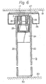
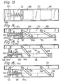
- the pressing bed 4 has sliding portions 4a and 4b which are held in engaging guide portions 1 a and 1 b of the lower frame 1, respectively. When the pressing bed 4 is moved in an upward direction, the sliding portion 4a is engaged with the guide portion 1 a. When the pressing bed 4 is moved in a downward direction, the sliding portion 4b is engaged with the guide portion 1 b.
- Indicated as 8 is a bracket rigidly fitted on one end of the sliding bed 3 by some suitable means such as welding, and with an opening for screw 9 penetrating the sliding bed 3 from side to side. It is of course possible to make the bracket 8 and the sliding bed 3 integral.
- Indicated as 10 is a bracket arranged at one end of the lower frame 1. An opening 11 formed in the bracket 10 allows a bolt 12 to reach an opening 9 formed in the bracket 8 where the bolt 12 is screwed into the bracket 8. A bolt stopper 13 is located between the bracket 8 and the bracket 10. Indicated as 14 is a recess in which the head of the bolt 12 is held. Indicated as 15 is a plurality of spring supporting rods. The upper end of each spring supporting rod 15 is rigidly fitted to the lower surface of the upper frame 2 by some suitable means such as welding, and the lower end of each spring supporting rod 15 suspends the pressing bed 4.
- compression springs 16 are arranged along the spring supporting rod 15 between the lower surface of the upper frame 2 and the upper surface of the pressing bed 4, the pressing bed 4 urges the compression springs 16 upward for thereby raising the upper frame 2 to fix the partition wall between the ceiling and the floor.
- Indicated as 17 is a spacer placed between the upper surface of the upper frame 2 and the ceiling 19.
- Indicated as 18 is a hole formed in the side wall of the lower frame 1 for inspection of the inside thereof.
- Fig. 5 is a sectional view of the partition wall fastening unit showing a state in which the pressing bed 4 is raised to cause the upper frame 2 to urge the ceiling 19 through the spacer 17.
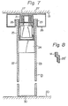
- the bolt 12 is rotated clockwise by means of a tool such as a wrench (not shown in the drawings)
- the bracket 8 as well as the sliding bed 3 is pulled towards the bracket 10.
- the sliding portion 4a of the pressing bed 4 is engaged to the guide portion 1 a of the lower frame 1, and the links 5 which are clockwise rotated by the action of the sliding portion 4a push up the pressing bed 4. Since the number of the links 5 is more than one, the upper surface of the pressing bed 4 is kept parallel with the upper surface of the lower frame 1.
- the sliding bed 3 when the sliding bed 3 is fitted at a position where the pressing bed 4 does not urge the upper frame 2, it is possible to float it with a constant pressure applied therein. In this case, since it makes a flexible construction, it can absorb any strain such as expansion or contraction due to earthquakes or ageing.
Landscapes
- Engineering & Computer Science (AREA)
- Architecture (AREA)
- Physics & Mathematics (AREA)
- Electromagnetism (AREA)
- Civil Engineering (AREA)
- Structural Engineering (AREA)
- Specific Sealing Or Ventilating Devices For Doors And Windows (AREA)
Claims (8)
Applications Claiming Priority (2)
| Application Number | Priority Date | Filing Date | Title |
|---|---|---|---|
| JP93029/77 | 1977-08-04 | ||
| JP9302977A JPS5428411A (en) | 1977-08-04 | 1977-08-04 | Device for fixing room partition wall |
Publications (2)
| Publication Number | Publication Date |
|---|---|
| EP0000717A1 EP0000717A1 (fr) | 1979-02-21 |
| EP0000717B1 true EP0000717B1 (fr) | 1981-12-30 |
Family
ID=14071058
Family Applications (1)
| Application Number | Title | Priority Date | Filing Date |
|---|---|---|---|
| EP78100460A Expired EP0000717B1 (fr) | 1977-08-04 | 1978-07-20 | Dispositif de fixation pour cloisons |
Country Status (6)
| Country | Link |
|---|---|
| US (1) | US4205498A (fr) |
| EP (1) | EP0000717B1 (fr) |
| JP (1) | JPS5428411A (fr) |
| AU (1) | AU528890B2 (fr) |
| CA (1) | CA1083772A (fr) |
| DE (1) | DE2861466D1 (fr) |
Families Citing this family (32)
| Publication number | Priority date | Publication date | Assignee | Title |
|---|---|---|---|---|
| NZ214968A (en) * | 1985-02-05 | 1989-04-26 | Alec David Ward | Screen retained between spaced apart rails |
| SE454582B (sv) * | 1985-11-12 | 1988-05-16 | Cassetteboats Ab | Lasanordning exv for hoplasning av kasettartade pontoner |
| DE3619393A1 (de) * | 1986-06-09 | 1987-12-10 | Hueppe Gmbh | Zweischaliges teleskopelement fuer eine bewegliche trennwand |
| DE3619392A1 (de) * | 1986-06-09 | 1987-12-10 | Hueppe Gmbh | Zweischaliges teleskopelement einer beweglichen trennwand |
| DE4026098C1 (en) * | 1990-08-17 | 1991-12-12 | Hueppe Form Sonnenschutz- Und Raumtrennsysteme Gmbh, 2900 Oldenburg, De | Room partition of displaceable wall elements - which have support bolts, each horizontally, slidably mounted w.r.t. another one |
| US5406761A (en) * | 1992-06-19 | 1995-04-18 | Huppe Form Sonnenschutzund Raumtrennsysteme Gmbh | Room-space partition made of movable wall elements |
| FR2705708B1 (fr) * | 1993-05-24 | 1995-08-18 | Tognoni Marcello | Dispositif d'isolation phonique de bâtiment. |
| FR2755160B1 (fr) * | 1996-10-31 | 1999-01-15 | Dra Associes | Procede de realisation d'un cloisonnement demontable ainsi que le dispositif de mise en oeuvre |
| US20030221392A1 (en) * | 2002-05-30 | 2003-12-04 | Alexander Furman | Paneling system and method of installing |
| US10563399B2 (en) | 2007-08-06 | 2020-02-18 | California Expanded Metal Products Company | Two-piece track system |
| US10619347B2 (en) | 2007-08-22 | 2020-04-14 | California Expanded Metal Products Company | Fire-rated wall and ceiling system |
| US8671632B2 (en) | 2009-09-21 | 2014-03-18 | California Expanded Metal Products Company | Wall gap fire block device, system and method |
| US10184246B2 (en) | 2010-04-08 | 2019-01-22 | California Expanded Metal Products Company | Fire-rated wall construction product |
| US8381448B2 (en) * | 2010-05-04 | 2013-02-26 | Special-Lite, Inc. | Adjustable door sweep |
| US12215498B2 (en) | 2012-01-20 | 2025-02-04 | Cemco, Llc | Fire-rated joint system |
| US10077550B2 (en) | 2012-01-20 | 2018-09-18 | California Expanded Metal Products Company | Fire-rated joint system |
| AT512642B1 (de) * | 2012-04-19 | 2013-10-15 | Jan Werner | Flexibles Wandsystem |
| US9920522B2 (en) * | 2013-08-19 | 2018-03-20 | Rogers Athletic Company, Inc. | Demountable barrier system |
| DE102015108663A1 (de) * | 2015-06-01 | 2016-12-01 | Dorma Deutschland Gmbh | Trennwandelement |
| WO2019152887A1 (fr) | 2018-02-01 | 2019-08-08 | Oldcastle Building Envelope, Inc. | Système et procédé de paroi démontable |
| US10753084B2 (en) | 2018-03-15 | 2020-08-25 | California Expanded Metal Products Company | Fire-rated joint component and wall assembly |
| US11162259B2 (en) | 2018-04-30 | 2021-11-02 | California Expanded Metal Products Company | Mechanically fastened firestop flute plug |
| US11111666B2 (en) | 2018-08-16 | 2021-09-07 | California Expanded Metal Products Company | Fire or sound blocking components and wall assemblies with fire or sound blocking components |
| US10914065B2 (en) | 2019-01-24 | 2021-02-09 | California Expanded Metal Products Company | Wall joint or sound block component and wall assemblies |
| US11268274B2 (en) | 2019-03-04 | 2022-03-08 | California Expanded Metal Products Company | Two-piece deflection drift angle |
| US11920343B2 (en) * | 2019-12-02 | 2024-03-05 | Cemco, Llc | Fire-rated wall joint component and related assemblies |
| CN111502331B (zh) * | 2020-05-11 | 2021-12-24 | 河北福榕筑建设工程有限公司 | 一种建筑房屋非承重墙免钻高稳定性拆卸方法 |
| US12454824B2 (en) | 2020-08-19 | 2025-10-28 | Cemco, Llc | Building joint with compressible firestopping component |
| US12024881B1 (en) | 2021-01-20 | 2024-07-02 | Gordon Sales, Inc. | Telescoping wall gap filler assembly |
| US12209407B1 (en) | 2021-01-20 | 2025-01-28 | Gordon Sales, Inc. | Narrow gap filling structure |
| US12607009B2 (en) | 2021-12-27 | 2026-04-21 | Cemco, Llc | Fire-rated gaskets and wall assemblies |
| CN115162570B (zh) * | 2022-08-01 | 2024-03-12 | 杭州鼎梦建设有限公司 | 一种装配式室内装饰隔墙及其施工方法 |
Family Cites Families (16)
| Publication number | Priority date | Publication date | Assignee | Title |
|---|---|---|---|---|
| US1311127A (en) * | 1919-07-22 | And one-eigkhth to john s | ||
| CA847012A (en) * | 1970-07-21 | R. Mcnair Graham | Clamping device for demountable partition | |
| US1561195A (en) * | 1922-12-07 | 1925-11-10 | Szymkowiak Anton | Weather stop |
| FR629701A (fr) * | 1927-02-23 | 1927-11-16 | Voor Controle Bureau | Bourrelet-joint réglable pour portes et autres analogues |
| GB274376A (en) * | 1927-02-26 | 1927-07-21 | Voor Controle Associate En Tru | Adjustable draught, dust and weather excluder for doors and the like |
| US1709419A (en) * | 1928-03-19 | 1929-04-16 | John E Sward | Automatic weather strip |
| FR1164454A (fr) * | 1957-01-15 | 1958-10-09 | D App Electr S E C A M Soc D E | Plinthe d'étanchéité, automatique, pour portes et analogues |
| US2949983A (en) * | 1958-01-16 | 1960-08-23 | Gartner Fritz | Means for supporting and clamping a hollow metal post relatively to ceilings or walls |
| US3292321A (en) * | 1963-12-24 | 1966-12-20 | Schans Paul A Vander | Mobile partition |
| US3250314A (en) * | 1964-02-17 | 1966-05-10 | Wayne Iron Works | Seal for folding partition |
| US3327439A (en) * | 1964-10-21 | 1967-06-27 | Ralph W Eatough | Wall panel locking actuator |
| US3638376A (en) * | 1970-01-05 | 1972-02-01 | Hough Mfg Corp | Portable partition |
| JPS5238019Y2 (fr) * | 1971-09-25 | 1977-08-30 | ||
| JPS4926977U (fr) * | 1972-06-12 | 1974-03-07 | ||
| BE818269A (fr) * | 1973-07-31 | 1974-11-18 | Parois se supportant d'elles-memes | |
| JPS609356Y2 (ja) * | 1975-03-01 | 1985-04-03 | 台太郎 佐藤 | 遮音スライデイングウオ−ル |
-
1977
- 1977-08-04 JP JP9302977A patent/JPS5428411A/ja active Granted
-
1978
- 1978-05-10 US US05/904,712 patent/US4205498A/en not_active Expired - Lifetime
- 1978-07-04 CA CA306,692A patent/CA1083772A/fr not_active Expired
- 1978-07-11 AU AU37931/78A patent/AU528890B2/en not_active Expired
- 1978-07-20 EP EP78100460A patent/EP0000717B1/fr not_active Expired
- 1978-07-20 DE DE7878100460T patent/DE2861466D1/de not_active Expired
Also Published As
| Publication number | Publication date |
|---|---|
| AU3793178A (en) | 1980-01-17 |
| JPS5540748B2 (fr) | 1980-10-20 |
| AU528890B2 (en) | 1983-05-19 |
| JPS5428411A (en) | 1979-03-03 |
| CA1083772A (fr) | 1980-08-19 |
| US4205498A (en) | 1980-06-03 |
| DE2861466D1 (en) | 1982-02-18 |
| EP0000717A1 (fr) | 1979-02-21 |
Similar Documents
| Publication | Publication Date | Title |
|---|---|---|
| EP0000717B1 (fr) | Dispositif de fixation pour cloisons | |
| US3465846A (en) | Installation for approaching portions of an airplane | |
| JPH01142149A (ja) | 建築用外装システム | |
| US4846443A (en) | Floor covering installation tool | |
| US5181694B1 (en) | Floor covering installation tool | |
| ITTR940003U1 (it) | Monoblocco cm1 | |
| EP1249548A1 (fr) | Elément de paroi d'une paroi coulissante | |
| JP6735141B2 (ja) | 扉装置における補強中柱の設置構造 | |
| GB2417046A (en) | Hinged access cover | |
| KR102697001B1 (ko) | 커튼월용 연결 장치 및 이를 포함하는 커튼 월 | |
| US3755967A (en) | Hydraulically operated window unit | |
| JP6489748B2 (ja) | 防水扉 | |
| JP3872941B2 (ja) | 間仕切壁 | |
| JP2591447Y2 (ja) | 枠体の取付け装置 | |
| JP6735373B2 (ja) | 防水扉 | |
| JPH0455196Y2 (fr) | ||
| JPH0433352B2 (fr) | ||
| JP2002194942A (ja) | 移動式パネル装置 | |
| JP2002038635A (ja) | 間仕切壁 | |
| CN222749928U (zh) | 一种便于调节的悬挂式动力柜 | |
| JPH076459Y2 (ja) | 受付用カウンター | |
| JPH0348973B2 (fr) | ||
| JPH07119230A (ja) | カーテンウォールのパネル取付方法 | |
| JPS6244007Y2 (fr) | ||
| JP3808848B2 (ja) | 外壁用エキスパンション・ジョイント |
Legal Events
| Date | Code | Title | Description |
|---|---|---|---|
| PUAI | Public reference made under article 153(3) epc to a published international application that has entered the european phase |
Free format text: ORIGINAL CODE: 0009012 |
|
| AK | Designated contracting states |
Designated state(s): CH DE FR GB NL |
|
| 17P | Request for examination filed | ||
| GRAA | (expected) grant |
Free format text: ORIGINAL CODE: 0009210 |
|
| AK | Designated contracting states |
Designated state(s): CH DE FR GB NL |
|
| REF | Corresponds to: |
Ref document number: 2861466 Country of ref document: DE Date of ref document: 19820218 |
|
| PGFP | Annual fee paid to national office [announced via postgrant information from national office to epo] |
Ref country code: FR Payment date: 19840724 Year of fee payment: 7 |
|
| PGFP | Annual fee paid to national office [announced via postgrant information from national office to epo] |
Ref country code: DE Payment date: 19840830 Year of fee payment: 7 |
|
| PGFP | Annual fee paid to national office [announced via postgrant information from national office to epo] |
Ref country code: CH Payment date: 19841029 Year of fee payment: 7 |
|
| PGFP | Annual fee paid to national office [announced via postgrant information from national office to epo] |
Ref country code: NL Payment date: 19870731 Year of fee payment: 10 |
|
| PG25 | Lapsed in a contracting state [announced via postgrant information from national office to epo] |
Ref country code: GB Effective date: 19890720 |
|
| PG25 | Lapsed in a contracting state [announced via postgrant information from national office to epo] |
Ref country code: CH Effective date: 19890731 |
|
| PG25 | Lapsed in a contracting state [announced via postgrant information from national office to epo] |
Ref country code: NL Effective date: 19900201 |
|
| GBPC | Gb: european patent ceased through non-payment of renewal fee | ||
| NLV4 | Nl: lapsed or anulled due to non-payment of the annual fee | ||
| PG25 | Lapsed in a contracting state [announced via postgrant information from national office to epo] |
Ref country code: FR Free format text: LAPSE BECAUSE OF NON-PAYMENT OF DUE FEES Effective date: 19900330 |
|
| REG | Reference to a national code |
Ref country code: CH Ref legal event code: PL |
|
| PG25 | Lapsed in a contracting state [announced via postgrant information from national office to epo] |
Ref country code: DE Effective date: 19900403 |
|
| REG | Reference to a national code |
Ref country code: FR Ref legal event code: ST |
|
| PLBE | No opposition filed within time limit |
Free format text: ORIGINAL CODE: 0009261 |
|
| STAA | Information on the status of an ep patent application or granted ep patent |
Free format text: STATUS: NO OPPOSITION FILED WITHIN TIME LIMIT |