EP0001014B1 - Perfectionnements concernant la réduction des vibrations de mécanismes - Google Patents
Perfectionnements concernant la réduction des vibrations de mécanismes Download PDFInfo
- Publication number
- EP0001014B1 EP0001014B1 EP78300315A EP78300315A EP0001014B1 EP 0001014 B1 EP0001014 B1 EP 0001014B1 EP 78300315 A EP78300315 A EP 78300315A EP 78300315 A EP78300315 A EP 78300315A EP 0001014 B1 EP0001014 B1 EP 0001014B1
- Authority
- EP
- European Patent Office
- Prior art keywords
- axis
- engine
- nodal
- support means
- force
- Prior art date
- Legal status (The legal status is an assumption and is not a legal conclusion. Google has not performed a legal analysis and makes no representation as to the accuracy of the status listed.)
- Expired
Links
- 230000007246 mechanism Effects 0.000 title claims description 84
- 230000009467 reduction Effects 0.000 title description 4
- 230000033001 locomotion Effects 0.000 claims description 19
- 230000009471 action Effects 0.000 claims description 18
- 125000004122 cyclic group Chemical group 0.000 claims description 15
- 230000010355 oscillation Effects 0.000 claims description 15
- 230000005540 biological transmission Effects 0.000 claims description 12
- 238000006073 displacement reaction Methods 0.000 claims description 8
- 238000013016 damping Methods 0.000 claims description 4
- 239000012530 fluid Substances 0.000 claims description 2
- 238000002955 isolation Methods 0.000 description 9
- 239000000725 suspension Substances 0.000 description 9
- 230000000694 effects Effects 0.000 description 6
- 239000000872 buffer Substances 0.000 description 5
- 238000010276 construction Methods 0.000 description 4
- 238000002485 combustion reaction Methods 0.000 description 3
- 230000006835 compression Effects 0.000 description 3
- 238000007906 compression Methods 0.000 description 3
- 230000005484 gravity Effects 0.000 description 3
- 230000006978 adaptation Effects 0.000 description 2
- 230000008901 benefit Effects 0.000 description 2
- 230000008859 change Effects 0.000 description 2
- 238000006243 chemical reaction Methods 0.000 description 2
- 230000008878 coupling Effects 0.000 description 2
- 238000010168 coupling process Methods 0.000 description 2
- 238000005859 coupling reaction Methods 0.000 description 2
- 230000001419 dependent effect Effects 0.000 description 2
- 238000010586 diagram Methods 0.000 description 2
- 230000006698 induction Effects 0.000 description 2
- 230000001502 supplementing effect Effects 0.000 description 2
- 230000001052 transient effect Effects 0.000 description 2
- 230000001010 compromised effect Effects 0.000 description 1
- 238000000034 method Methods 0.000 description 1
- 230000003534 oscillatory effect Effects 0.000 description 1
Images


Classifications
-
- B—PERFORMING OPERATIONS; TRANSPORTING
- B62—LAND VEHICLES FOR TRAVELLING OTHERWISE THAN ON RAILS
- B62M—RIDER PROPULSION OF WHEELED VEHICLES OR SLEDGES; POWERED PROPULSION OF SLEDGES OR SINGLE-TRACK CYCLES; TRANSMISSIONS SPECIALLY ADAPTED FOR SUCH VEHICLES
- B62M7/00—Motorcycles characterised by position of motor or engine
- B62M7/02—Motorcycles characterised by position of motor or engine with engine between front and rear wheels
-
- B—PERFORMING OPERATIONS; TRANSPORTING
- B27—WORKING OR PRESERVING WOOD OR SIMILAR MATERIAL; NAILING OR STAPLING MACHINES IN GENERAL
- B27B—SAWS FOR WOOD OR SIMILAR MATERIAL; COMPONENTS OR ACCESSORIES THEREFOR
- B27B17/00—Chain saws; Equipment therefor
- B27B17/0033—Devices for attenuation of vibrations
-
- F—MECHANICAL ENGINEERING; LIGHTING; HEATING; WEAPONS; BLASTING
- F16—ENGINEERING ELEMENTS AND UNITS; GENERAL MEASURES FOR PRODUCING AND MAINTAINING EFFECTIVE FUNCTIONING OF MACHINES OR INSTALLATIONS; THERMAL INSULATION IN GENERAL
- F16F—SPRINGS; SHOCK-ABSORBERS; MEANS FOR DAMPING VIBRATION
- F16F7/00—Vibration-dampers; Shock-absorbers
- F16F7/10—Vibration-dampers; Shock-absorbers using inertia effect
- F16F7/104—Vibration-dampers; Shock-absorbers using inertia effect the inertia member being resiliently mounted
-
- B—PERFORMING OPERATIONS; TRANSPORTING
- B60—VEHICLES IN GENERAL
- B60G—VEHICLE SUSPENSION ARRANGEMENTS
- B60G2202/00—Indexing codes relating to the type of spring, damper or actuator
- B60G2202/20—Type of damper
- B60G2202/25—Dynamic damper
Definitions
- This invention relates to apparatus that comprises support or carrier means to which is attached a mechanism having at least one element rotating at a fundamental or first-order frequency and one or more cyclically displaceable further elements directly or indirectly mechanically connected to said at least one element, the displacement of said cyclically displaceable element or elements producing a cyclic linear force of fundamental frequency and harmonics thereof acting on the same line and in which mechanism are rotary balancing means integral with or attached to said rotating element or elements.
- the invention is concerned with means by which a mechanism for transmitting power can be mounted to be freely displaceable on the support means by such cyclic exciting forces without the mechanism being unduly sensitive to forces generated by the power transmission.
- ACLEF cyclic linear force of fundamental frequency together with any harmonics thereof acting along the same line
- ACLEF aggregate cyclic linear exciting force
- the mechanism comprises a rotary crank, connecting rod and slider-the slider being a reciprocating piston- as in internal combustion engines, and fluid motors and compressors.
- a rotary crank, connecting rod and slider-the slider being a reciprocating piston- as in internal combustion engines, and fluid motors and compressors.
- the mechanism comprises a multiplicity of sliders (e.g. six pistons in an in-line engine), or an integral mirror image construction (e.g. the Ariel "Square four" motor cycle engine), or a non-power contributing balancer piston, or one or more contrarotating masses, or other additional moving elements.
- the line of action of the ACLEF may pass through the centre of gravity of the mechanism of which the cyclically displaceable elements are a part but more usually said line of action will be spaced from the centre of gravity of the complete mechanism that these elements are a part of, and there will be other elements, such as induction and exhaust means, a drive output transmission and the like, which cannot be normally be disposed symmetrically.
- the construction is arranged to permit pivotal oscillation about an axis coincident with the axis of the engine drive chain sprocket or substantially on a line between that sprocket axis and the axis of the driven sprocket on the rear wheel.
- the present invention provides a solution to this problem for apparatus comprising a mechanism having at least one element arranged to rotate at a fundamental or first order frequency and one or more cyclically displaceable further elements mechanically connected to said at least one element, the displacements of said cyclically displaceable element or elements producing an aggregate cyclic linear force of fundamental frequency and harmonics thereof acting on the same line, said line of action of the force being close to but spaced from the centre of mass of the mechanism.
- the mechanism comprises rotary balancing means integral with or attached to said rotatable element or elements for balancing at least the major part of any rotating force of said fundamental frequency produced by said rotatable element or elements, and is mounted on support means through constraining means that confine movements of the mechanism relative to the support means to movements about an axis at or adjacent a nodal axis about which the mechanism will tend to move under the action of the aggregate linear exiting force, whereby the transmission of said aggregate linear exciting force to said support means is at least substantially reduced, power transmitting means connecting the mechanism to a member also mounted on said support means, said power transmitting means being so disposed that the forces developed by the transmission of power through said transmitting means between the mechanism and said member produce substantially no torque component about the nodal axis.
- the mechanism cannot ordinarily be allowed unlimited freedom of movement in the one degree permitted by the attachment means. Unless the disposition of the mechanism relative to the support means is such that gravity urges the mechanism to a suitable median position, it will then be necessary to establish the median position by elastic means between the mechanism and the support means.
- the stiffness of the elastic means is preferably less than that which could sustain a natural frequency of the mechanism as a whole relative to the support means below a minimum frequency of the lowest order of the ACLEF within the normal range of operation of the mechanism.
- Figure 1 illustrates a dynamic system in which a mass M, here regarded as being freely suspended in space without gravitational force acting on it, has a centre of mass C.
- An impulse P acts on the mass at a radial distance h from C.
- the mass swings about some point X a distance x from C along an extension of the same radius.
- Figure 1 shows also equal and opposite impulses P' and P" both of the same magnitude as P and acting through the centre of mass parallel to P.
- the impulses P and P' constitute a couple or moment Ph, whence where I is the rotational moment of inertia of the mass about C and a is the angular velocity about C.
- the impulse P" acting at the centre of mass will produce a linear displacement, whence where v is the translational velocity at the centre of mass C.
- the mass is a mechanism with one or more displaceable elements that, by their movement, generate a linear cyclic force, by mounting the mechanism on a support or carrier means so that it is constrained to be able only to pivot about the nodal axis X, none of that force will be transmitted to the support means.
- FIG. 2 illustrates an embodiment of the dynamic system of Figure 1 as a reciprocating piston engine 20 which may have a single cylinder, or a two cylinder in line configuration. Shown in schematic outline is crank 21 a rotating on crankshaft axis 20a, connecting rod 21 b and piston or slider 21 c reciprocating in cylinder 20b, as well as a balancing mass 21 d rotating with the crank.
- crank 21 a rotating on crankshaft axis 20a
- connecting rod 21 b and piston or slider 21 c reciprocating in cylinder 20b
- balancing mass 21 d rotating with the crank.
- These parts may be generally conventional, except that as already indicated and balancing mass is arranged to balance substantially all the out-of-balance rotating force of the fundamental or first order frequency represented by the frequency of rotation of the crank. Similar arrangements apply in the other mechanisms to be described below and further illustration is therefore not necessary, it being understood that the balancing means may be of any conventional form provided it is arranged to fulfil the function now required of it.
- the ending 20 has an output drive chain 22 to drive sprocket 24 having a mounting point 26a on support or carrier means 26.
- a pair of pivot links 28, 30 extending from further mounting points 26b, 26c connect the engine to the mounting 26. Both ends of the links are pivoted on axes perpendicular to the plane of the drawing, so that all movements out of the driving plane are prevented and the engine is constrained effectively to a single degree of freedom, pivoting about the nodal axis.
- the weight of the engine is supported through the links and a tension spring 32 between it and mounting point 26d on the support means.
- the spring preferably has a low rate (force/displacement characteristic) or even a zero rate.
- both links are put in compression by the forces generated in running the engine, but one or both may be disposed on the opposite side of the engine, while still being located on axial lines radiating from the nodal axis, and will then be in tension.
- Figure 3 illustrates a motor cycle in which a single-cylinder engine and gearbox power unit 102 that may be of generally conventional form, is mounted on the vehicle main frame 104 through pivot links 106, 108 that have pivot axes 106a, 106b, 108a, 108b, perpendicular to the plane of the drawing.
- the links have longitudinal axes that intersect at the nodal axis X.
- the disposition of the links means they are put in compression by the tension in the chain drive 110 to rear wheel 112 mounted on radius arm 114 in conventional manner, and the links constrain the unit 102 so that it can only move pivotally about X.
- a piston damper 120 shown connected between the unit and the cycle frame is a friction damper having a damping effect substantially independent of its displacement or velocity.
- the engine and its drive are so arranged that the tensioned length of the drive chain 110 through which the engine torque is transmitted is itself on a line passing through the nodal axis X.
- Figure 3 shows a separate suspension spring 116 for the power unit, it is possible to employ the engine exhaust pipe, secured by brackets to the main frame of the bicycle, as a low-rate suspension spring in place of, or supplementing, the spring 116. It is possible to employ an air induction pipe of the engine in a similar manner.
- the effective stiffness of the resilient suspension should be less than that which would sustain a natural frequency of oscillation of the mechanism relative to the support means equal to the minimum fundamental frequency of the ACLEF within the range of operation of the mechanism. In general when the invention is employed with reciprocating piston engines and motors it will be practical to arrange that this frequency is considerably lower than the fundamental frequency of the ACLEF.
- the buffer 118 is able to act as a resilient over-travel stop supplementing the action of the damper. It may be preferred to adjust or disengage the damper, e.g.
- damping means may remain operative and serve a useful purpose in limiting the effects of any significant transient external disturbances, such as may occur when travelling over an uneven surface.
- any over-travel buffers such as the buffer 118
- the rotary out-of-balance forces that the mechanism, i.e. the unit 102, generates will preferably be completely balanced when the mechanism is running.
- the ACLEF P acting a spacing from the centre of Mass C of the mechanism, will cause the mechanism to oscillate about the nodal axis.
- the masses generating this force form a relatively small part of the total mass of the mechanism so that the amplitude of oscillation in normal running conditions will be very small. For example, if the crank and piston in this single cylinder engine have 5% of the mass of the unit and the piston stroke is 10 cm, the opposite movement of the unit will be 0.5 cm. Because of the low rate of the spring and the characteristics of the damper only a negligible portion of the force P will be transmitted to the frame through these components so that it is substantially isolated from the vibration of the mechanism.
- the low amplitude of oscillation allows the actual axis of pivoting to be offset from the exact nodal axis to some extent without unduly affecting the efficiency with which the vibration induced by the ACLEF is isolated from the support frame.
- it is thus possible still to obtain a useful advantage of a pivot axis is provided only approximately in the region of the nodal axis.
- FIG. 4 illustrates in plan view a shaft drive arrangement with a single cylinder engine constrained to be able only to pivot about the nodal axis, as already described, by an upper link 28 and a parallel pair of lower links 30.
- the axis of the output shaft 36 projecting from the engine crankcase is perpendicular to the nodal axis and is provided with a coupling 38, e.g. a universal coupling, for a shaft (not shown) separately supported by the support means that are here indicated only by the pivot mountings of the pivot links.
- the shaft axis is in a plane perpendicular to the nodal axis. Changes of the torque load on the shaft, whether due to a power output from or input to the mechanism, do not therefore cause changes in the deflection of the supporting resilient means. This is the same effect as has already been described with reference to a chain drive in which the axis of the tensioned length of the chain intersects the nodal axis.
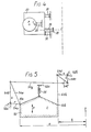
- Figure 5 illustrates another pivot linkage that can be employed in apparatus according to the invention, mounting a mechanism 50 on elements 52a, 52b of a support means (not shown).
- this linkage the relative lengths of links 54a, 54b, 54c, 54d (these lengths being designated r, s, t, u respectively) proportion the relative movements of attachments points 50a, 50b of the mechanism about the nodal axis X.
- the links 54a, 54b form a triangular frame with link 54e
- a link 54f similarly forms a triangular frame with links 54c, 54d and each said frame thus moves as a rigid member.
- the two triangular frames are interconnected by a further link 54g.
- the mechanism attachment point 50a is at the junction between links 54a, 54e and the attachment point 50b is at one end of another link 54h connected to the junction between the links 54d, 54f.
- the ratio of the displacement of 50a to 50b is required to be equal to the ratio a:b. This is achieved by positioning the attachment points 50a, 50b and selecting the indicated lengths r, s, t, u of the links so that The drawing also shows a suspension spring 56 between the mechanism and a further support means attachment point 52c.
- Figure 6 illustrates a further alternative mounting in which the mechanism 50 is connected to its support means, using two links 62a, 62b that incorporate resilient suspension means and damping means in their connections.
- link 62a has one of its pivot connections 64 comprising a torsion bar and the other link incorporates a friction disc damper 66.
- the longitudinal axes of the links intersect at or adjacent the nodal axis of the mechanism.
- the torsion bar connection is shown in more detail in Figure 7.
- the support means comprises a tubular socket 68 in which a terminal sleeve 70 at the end of the link 62a is rotatably mounted so as to provide the pivoting freedom of a pin joint.
- a resilient torsion tube 72 is rotatable.
- a first plate 74 secures it to the socket 68 and at the other end a second plate 76 secures it to the sleeve 70.
- the damper 66 is of a form that acts substantially independently of its rate and magnitude of displacement as it is intended only to damp excessively large oscillations, as will be further described below.
- the vibration isolation means described will be equally effective with different frequency components having a common line of action, and also with common frequency components having different lines of action but being in phase with each other.
- the valve push rods for example, will move on axes close to the cylinder axes and the linear out-of-balance forces generated by such auxiliary elements of the mechanism may be isolated together with the main linear out-of-balance forces.
- e is related to the position of X' in the following formula: where f3 is the angle between a line from the centre of mass C to the axis X' and a perpendicular through C to the line of action of the impulse P, and a is the distance between C and X'.
- the formula defines, in terms of a and f3 the boundary of an area around the normal axis for obtaining at least that specified degree of isolation.
- x I/ (Mh).
- the line of any force transmitted should lie in a plane that also contains the nodal axis.
- the effect of not observing this condition is that the mean position of the mechanism will change in dependence upon the magnitude of the transmitted force, but that may be tolerated if the mechanism still has space to oscillate freely under the action of the ACLEF.
- FIG. 9 illustrates such apparatus schematically, comprising a support or carrier frame 180, and a piston engine or motor 182 attached to the frame by constraining elements in the form of pivot links 184, 186 and a suspension or centralising spring 188 the arrangement of these being as already described in principle.
- Mounted on the frame is a saw chain blade or guide 190, around which the saw chain 192 itself extends to be driven by a sprocket 194 on the engine output shaft.
- a felling dog 196 is secured to the frame 180 in known manner.
Landscapes
- Engineering & Computer Science (AREA)
- Mechanical Engineering (AREA)
- Life Sciences & Earth Sciences (AREA)
- Chemical & Material Sciences (AREA)
- Combustion & Propulsion (AREA)
- General Engineering & Computer Science (AREA)
- Wood Science & Technology (AREA)
- Forests & Forestry (AREA)
- Transportation (AREA)
- Vibration Prevention Devices (AREA)
Claims (12)
Applications Claiming Priority (2)
| Application Number | Priority Date | Filing Date | Title |
|---|---|---|---|
| GB3616577 | 1977-08-30 | ||
| GB3616577 | 1977-08-30 |
Publications (2)
| Publication Number | Publication Date |
|---|---|
| EP0001014A1 EP0001014A1 (fr) | 1979-03-07 |
| EP0001014B1 true EP0001014B1 (fr) | 1982-05-19 |
Family
ID=10385573
Family Applications (1)
| Application Number | Title | Priority Date | Filing Date |
|---|---|---|---|
| EP78300315A Expired EP0001014B1 (fr) | 1977-08-30 | 1978-08-22 | Perfectionnements concernant la réduction des vibrations de mécanismes |
Country Status (4)
| Country | Link |
|---|---|
| US (1) | US4261105A (fr) |
| EP (1) | EP0001014B1 (fr) |
| JP (1) | JPS5447077A (fr) |
| DE (1) | DE2861850D1 (fr) |
Families Citing this family (10)
| Publication number | Priority date | Publication date | Assignee | Title |
|---|---|---|---|---|
| GB2121509B (en) * | 1982-04-26 | 1986-07-23 | Nat Res Dev | Active mounting of vehicle engine |
| JPS61113583A (ja) * | 1984-10-17 | 1986-05-31 | 本田技研工業株式会社 | 自動二輪車等の車両におけるパワ−ユニツト懸架装置 |
| US4670985A (en) * | 1984-12-17 | 1987-06-09 | Mcculloch Corporation | Vibration mount in a chainsaw |
| DE19631033B4 (de) * | 1996-08-01 | 2009-05-28 | Fa. Andreas Stihl | Tragbares, handgeführtes Arbeitsgerät mit einem hinteren Handgriff |
| DE19849770B4 (de) * | 1998-10-28 | 2016-03-03 | Linde Material Handling Gmbh | Gabelstapler |
| JP2001247073A (ja) * | 2000-03-02 | 2001-09-11 | Honda Motor Co Ltd | 車体フレーム構造 |
| JP3801901B2 (ja) * | 2001-10-23 | 2006-07-26 | 本田技研工業株式会社 | 自動二輪車のエンジン取付構造 |
| US7369982B2 (en) | 2003-06-04 | 2008-05-06 | Stmicroelectronics, Inc. | Multi-mode smart card emulator and related methods |
| US8490663B2 (en) * | 2008-02-15 | 2013-07-23 | Terrill W. Wright | Remotely operated mobile cutting apparatus |
| DE102008064007A1 (de) * | 2008-12-19 | 2010-06-24 | Andreas Stihl Ag & Co. Kg | Heckenschere |
Family Cites Families (14)
| Publication number | Priority date | Publication date | Assignee | Title |
|---|---|---|---|---|
| BE564478A (fr) * | 1900-01-01 | |||
| CH96405A (de) | 1921-02-14 | 1922-10-02 | Motorenfabrik Oberursel A G | Befestigung eines Fahrradhilfsmotors am Fahrradrahmen. |
| GB222750A (en) * | 1924-02-14 | 1924-10-09 | Giovanni Frova | Spring suspension of an auxiliary engine on a cycle frame |
| US2091698A (en) * | 1936-05-02 | 1937-08-31 | Anthony Dev Company | Cycle construction |
| DK71320C (da) * | 1945-08-24 | 1950-07-31 | An Moto Garelli Soc | Motorophængningsanordning ved cykler. |
| US2574824A (en) * | 1945-08-24 | 1951-11-13 | Garelli Adalberto | Supporting system for bicycle engines |
| US3224473A (en) * | 1962-04-03 | 1965-12-21 | Dobbertin Gunther Hein Wilhelm | Portable engine-driven chain saws |
| US3410358A (en) * | 1966-12-20 | 1968-11-12 | Caterpillar Tractor Co | Damped and tuned dynamic absorber for vehicles |
| US3722612A (en) * | 1970-06-17 | 1973-03-27 | Norton Villiers Ltd | Chain driven vehicles |
| US3733700A (en) * | 1970-08-19 | 1973-05-22 | J Notaras | Dual grip handle for power tools |
| SU419377A1 (ru) | 1972-03-10 | 1974-03-15 | Э. А. Келлер, М. Н. Бибиков , А. А. Попов Пермский политехнический институт | Переносная моторная пила |
| JPS5131436A (en) * | 1974-09-12 | 1976-03-17 | Honda Motor Co Ltd | Pawaayunitsuto suinguhoshikijidonirinsha |
| US4010544A (en) * | 1975-03-21 | 1977-03-08 | Textron, Inc. | Vibration reducing system for single cylinder fluid pressure engine |
| SU564959A1 (ru) * | 1976-03-29 | 1977-07-15 | Пермский политехнический институт | Переносна моторна пила |
-
1978
- 1978-08-22 EP EP78300315A patent/EP0001014B1/fr not_active Expired
- 1978-08-22 DE DE7878300315T patent/DE2861850D1/de not_active Expired
- 1978-08-24 US US05/936,615 patent/US4261105A/en not_active Expired - Lifetime
- 1978-08-30 JP JP10501078A patent/JPS5447077A/ja active Pending
Also Published As
| Publication number | Publication date |
|---|---|
| JPS5447077A (en) | 1979-04-13 |
| DE2861850D1 (en) | 1982-07-08 |
| US4261105A (en) | 1981-04-14 |
| EP0001014A1 (fr) | 1979-03-07 |
Similar Documents
| Publication | Publication Date | Title |
|---|---|---|
| US4694650A (en) | Externally tuned vibration absorber | |
| US5282397A (en) | Engine balancing system having at least one pivoting counterbalance weight | |
| US3811528A (en) | Vehicle motor mounts | |
| US4261105A (en) | Reduction of vibration from mechanisms | |
| JPH0134839B2 (fr) | ||
| JPH0255280B2 (fr) | ||
| US2079227A (en) | Means adapted to reduce the torsional oscillations of crankshafts | |
| GB2086007A (en) | Vibration Damping Handle | |
| US2241527A (en) | Oscillating mechanical system for the transmission of power | |
| US4440257A (en) | Vibration-insulating bearing arrangement for a drive unit | |
| JPH09184545A (ja) | ピストン往復内燃機関における消振装置 | |
| RU2027069C1 (ru) | Вибровозбудитель инерционного движителя | |
| RU2026504C1 (ru) | Вибровозбудитель инерционного движителя | |
| CN220111515U (zh) | 一种位移输出型激振器 | |
| JPS5973644A (ja) | 熱ガス機関のバランサ装置 | |
| EP1904758A1 (fr) | Dispositif a carter d'arbres principal pour machines a piston destine a agir sur la force/le moment se produisant en fonctionnement sur les elements de soutien du bloc-cylindre | |
| US2156484A (en) | Device for imparting impulses to a system | |
| JPH026649B2 (fr) | ||
| SU1391874A1 (ru) | Машина ударного действи | |
| SU1747978A1 (ru) | Способ испытаний объекта на пространственную вибрацию и устройство дл его осуществлени | |
| RU2052570C1 (ru) | Дорожный каток | |
| SU808266A1 (ru) | Переносна моторна пила | |
| SU818990A1 (ru) | Вибрационный конвейер | |
| SU894260A1 (ru) | Виброизолирующее устройство | |
| SU543582A1 (ru) | Вибромашина |
Legal Events
| Date | Code | Title | Description |
|---|---|---|---|
| PUAI | Public reference made under article 153(3) epc to a published international application that has entered the european phase |
Free format text: ORIGINAL CODE: 0009012 |
|
| AK | Designated contracting states |
Designated state(s): BE CH DE FR GB LU NL SE |
|
| 17P | Request for examination filed | ||
| GRAA | (expected) grant |
Free format text: ORIGINAL CODE: 0009210 |
|
| AK | Designated contracting states |
Designated state(s): DE GB |
|
| REF | Corresponds to: |
Ref document number: 2861850 Country of ref document: DE Date of ref document: 19820708 |
|
| PGFP | Annual fee paid to national office [announced via postgrant information from national office to epo] |
Ref country code: DE Payment date: 19840814 Year of fee payment: 7 |
|
| PG25 | Lapsed in a contracting state [announced via postgrant information from national office to epo] |
Ref country code: DE Effective date: 19870501 |
|
| PG25 | Lapsed in a contracting state [announced via postgrant information from national office to epo] |
Ref country code: GB Free format text: LAPSE BECAUSE OF NON-PAYMENT OF DUE FEES Effective date: 19881117 |
|
| PLBE | No opposition filed within time limit |
Free format text: ORIGINAL CODE: 0009261 |
|
| STAA | Information on the status of an ep patent application or granted ep patent |
Free format text: STATUS: NO OPPOSITION FILED WITHIN TIME LIMIT |