EP0001171B1 - Dispositif pour envelopper les extrémités de rouleaux - Google Patents
Dispositif pour envelopper les extrémités de rouleaux Download PDFInfo
- Publication number
- EP0001171B1 EP0001171B1 EP78300342A EP78300342A EP0001171B1 EP 0001171 B1 EP0001171 B1 EP 0001171B1 EP 78300342 A EP78300342 A EP 78300342A EP 78300342 A EP78300342 A EP 78300342A EP 0001171 B1 EP0001171 B1 EP 0001171B1
- Authority
- EP
- European Patent Office
- Prior art keywords
- roll
- members
- extension
- tucking
- axial bore
- Prior art date
- Legal status (The legal status is an assumption and is not a legal conclusion. Google has not performed a legal analysis and makes no representation as to the accuracy of the status listed.)
- Expired
Links
- 238000009963 fulling Methods 0.000 claims description 53
- 239000000463 material Substances 0.000 claims description 15
- 238000000034 method Methods 0.000 claims description 14
- 230000015572 biosynthetic process Effects 0.000 claims description 5
- 230000000717 retained effect Effects 0.000 claims description 2
- 230000033001 locomotion Effects 0.000 description 5
- 230000007547 defect Effects 0.000 description 2
- 239000012530 fluid Substances 0.000 description 2
- 230000007246 mechanism Effects 0.000 description 2
- 239000002184 metal Substances 0.000 description 2
- 239000004033 plastic Substances 0.000 description 2
- 235000017166 Bambusa arundinacea Nutrition 0.000 description 1
- 235000017491 Bambusa tulda Nutrition 0.000 description 1
- 241001330002 Bambuseae Species 0.000 description 1
- 235000015334 Phyllostachys viridis Nutrition 0.000 description 1
- 239000011425 bamboo Substances 0.000 description 1
- 230000003111 delayed effect Effects 0.000 description 1
- 230000000994 depressogenic effect Effects 0.000 description 1
- 230000001788 irregular Effects 0.000 description 1
- 230000002093 peripheral effect Effects 0.000 description 1
- 238000004804 winding Methods 0.000 description 1
- 230000037303 wrinkles Effects 0.000 description 1
Images


Classifications
-
- B—PERFORMING OPERATIONS; TRANSPORTING
- B65—CONVEYING; PACKING; STORING; HANDLING THIN OR FILAMENTARY MATERIAL
- B65B—MACHINES, APPARATUS OR DEVICES FOR, OR METHODS OF, PACKAGING ARTICLES OR MATERIALS; UNPACKING
- B65B49/00—Devices for folding or bending wrappers around contents
- B65B49/08—Reciprocating or oscillating folders
-
- B—PERFORMING OPERATIONS; TRANSPORTING
- B65—CONVEYING; PACKING; STORING; HANDLING THIN OR FILAMENTARY MATERIAL
- B65B—MACHINES, APPARATUS OR DEVICES FOR, OR METHODS OF, PACKAGING ARTICLES OR MATERIALS; UNPACKING
- B65B25/00—Packaging other articles presenting special problems
- B65B25/14—Packaging paper or like sheets, envelopes, or newspapers, in flat, folded, or rolled form
- B65B25/146—Packaging paper or like sheets, envelopes, or newspapers, in flat, folded, or rolled form packaging rolled-up articles
- B65B25/148—Jumbo paper rolls
Definitions
- This invention relates to a wrapping device and more particularly to a device for wrapping rolls to cover their ends as well as their sides.
- a wrapping paper is wound with its ends slightly projected from the ends of the rolls and this projected cylindrical portion of the wrapping paper is tucked gradually towards the centre of the ends of the roll as the roll is rotated and a separate circular piece of wrapping paper is pasted thereon (U.S. Patent No. 2,368,213).
- a wrapping paper is wound with its ends projected by at least a length equal to the radius of the roll, then the projected wrapping paper is twisted by rotating the roll and pushed into the hole at the centre of the roll.
- the former method produces a good appearance because the ends of the roll are covered with a circular piece of wrapping paper.
- it has a fault in that the process of pasting on the circular piece of wrapping paper is troublesome and that it closes up the centre hole of the roll, making it inconvenient to transport.
- the latter method is simpler in its process than the former. However, it may impair the quality and appearance of the roll by the formation of irregular wrinkles on the wrapped ends. Therefore, it is used mainly for rolls of small diameter.
- the inventor previously proposed a first method of wrapping about a roll a paper pre-processed to have folds in the portions destined to extend cylindrically from the ends of the roll and then winding the folded portion and tucking it into the centre of the roll (Japanese Patent Disclosure No. 13984/77), and a second method wherein tucking members are positioned at equal spaces on the periphery at the ends of the rolls, the cylindrical portions of wrapped paper extending from the ends of the rolls are depressed towards the centre of the roll so that ridge portions are formed, whereafter the centre portion of the wrapping paper is pushed into the centre of the rolls and the ridge portions are laid in a fixed direction (Japanese Patent Disclosure No. 70691/77).
- U.S. Patent No. 2,066,414 provides a device for wrapping cylindrical containers or articles in which folds are formed in a cylindrical extension of wrapping material which extends beyond the ends of the article.
- This device includes at a single station a plurality of circumferentially spaced tucking members (153) and a plurality of internal projecting members (164), which cooperate with each other to provide alternate grooves and ridges in the extension.
- tucking members 153
- internal projecting members 164
- a plurality of radially movable internal projecting members (13) are provided in association with said tucking members (4) to assure correct ridge and groove formation and in that said projecting members and said plug means are disposed on a common axial shaft (11), said shaft being moved axially from a first operational position in which said projecting members contact the inner surface of the extension, to a second operational position in which said projecting members and said plug are clear of said extension and subsequently to a third operational position wherein said plug causes said portion of said extension to enter the axial bore.
- the device according to the present invention can wrap the ends of the roll neatly by producing even folds and prevent the central hole of the roll from being blocked. Accordingly, the present device is suitable particularly for a roll of large diameter.
- a roll 1 to be wrapped is rotated by rollers 3 (rotation and support mechanisms not shown) to have several wrappings of a wrapping paper 2 wound thereon so as to project from the ends of the roll 1. Consequently, the end portion 2' of the wrapping paper projects cylindrically from both ends of the roll 1.
- the length of the projected wrapping paper 2' should be slightly larger than the radius of the roll.
- a device for wrapping that end of the roll At either end of the roll 1, there is provided a device for wrapping that end of the roll.
- the device is mounted on a frame 9 and is adjusted to a prescribed distance from the end of the roll by moving the frame 9 supported by wheels 22 along a rail 23.
- a cylindrical frame 21 having a slightly larger diameter than that of the roll to be wrapped is provided on the frame 9.
- the cylindrical frame 21 has a number of tucking members 4 for tucking in the projected portion of the wrapping paper 2' placed at equal intervals about the circumference thereof.
- a fulcrum supporting shaft 6 for each tucking member 4 is supported by a bearing 5 fixed on the side of the cylindrical frame 21.
- the fulcrum supporting shafts 6 of the tucking members are connected by flexible joints 7 in a generally circular pattern ( Figure 2).
- An arm 10 is projected from the fulcrum supporting shaft of the topmost fulcrum supporting shaft 6, and a fluid pressure cylinder 8 is connected to the arm 10. Therefore, the operation of the fluid pressure cylinder 8 causes the tips of the tucking members 4 to turn simultaneously towards the center of the cylindrical frame round the fulcrum supporting shaft 6.
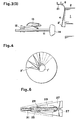
- a plug 14 having substantially the same diameter as that of the hole 1' projects from the frame 9, and the plug 14 is given an axial movement and slow rotational motion through a shaft 11.
- the shaft 11 of the plug 14 has a sliding base 12 and a fixed ring 19 fitted thereon.
- the sliding base 12 has pivotally attached thereto a number of radially extending main arms 16 equal to the number of tucking members 4.
- each main arm 16 is provided with a rotary piece 17 having welded thereon a projecting member 13 and the main arm 16, the rotary piece 17, an arm 18 and an arm 20 form a parallelogram.
- the lower end of the arm 20 is pivotally attached to the fixed ring 19. Therefore, when the sliding base 12 is caused to advance on the shaft 11 by rotation of driving screws 24', the link mechanism of the projecting members 13 all expand radially at one time and the tips 13' of the projecting members are placed between the tucking members 4. Then if the sliding base 12 is caused to retract by reverse rotation of the driving screws 24', the main arm 16 and the projecting members 13 are brought more parallel to the shaft 11, that is they are brought into a folded state.
- the driving screw 24' is rotated by a motor (not shown) in a box 24.
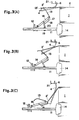
- the frame 9 is moved so as to position the fulcrum supporting shafts 6 of tucking members 4 near the end of the roll 1 which has been wound on its periphery with wrapping paper 2 by the roller 3 ( Figure 3(A)).
- the cylinder 8 When the fulcrum supporting shafts 6 are positioned near the end of the roll 1, the cylinder 8 is operated to turn all the tucking members 4 inward at the same time and the sliding base 12 is advanced to cause the projecting members 13 to rise and bring the tips 13' into contact with the inside of the cylinder of wrapping paper 2' projecting from the end of the roll 1.
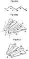
- the tucking members 4 contact the periphery of the cylinder of wrapping paper 2' projecting from the end of the roll 1 from the outside to produce groove portions, while the projecting members 13 contact the cylinder of wrapping paper from the inside at points lying between the tucking members to produce ridge portions ( Figure 3(B)).
- the tucking members 4 are caused to turn inward by further operation of the cylinder 8. Then, the sliding base 12 is caused to draw back so as to pucker up the projecting members 13. The operation of the projecting members is slightly delayed so that the cylinder of wrapping paper is always formed into grooves by the tucking members and into ridges by the projecting members.
- the , tucking members can be of rod or plate shape and can be made of plastic, wood or metal. They are of a length equal to, or somewhat less than, the thickness of the paper on the roll (from the surface to the center hole). When the structure shown in Figure 5- Figure 7 is used, the folds will be finished more neatly on the ends of the roll.
- projecting rails 26 are provided on the both sides of a bar member 25 having a fin, and triangular plates 27 are slidably inserted into the projecting rails 26.
- a cylinder 29 is fixed on the bar member 25 and connected with triangular plates 27 through a bracket 28.
- an elastic wire 30 is supported by a shaft 33 and rotated by a cylinder 31 placed at the tip of the bar member 25.
- a flexible piece 34 is provided on the tip of the tucking members as shown in Figure 9.
- This piece 34 is normally held in extended state by means of a spring 35, and when the wrapping paper is pushed in by the plug 14, it is caused to bend into the hollow hole under the force of the plug 14. Through this action the piece 34 protects the edge of the hole and also makes the folds neat.
- the projecting members 13 are made of a highly flexible wire material because the wrapping paper may be broken if the motions of the tucking members and the projecting members 13 are not smoothly coordinated.
- the material of these pieces can be metal, plastic, wood, bamboo, etc.
- the most appropriate relationship between the motions of the tucking and projecting members can be obtained by experiments and calculations, and it is preferable to control the hydraulic cylinder- actuating motor so that the tucking and projecting members can work in accordance with such relationship.
- the device for wrapping the ends of rolls according to this invention folds the cylinder of wrapping paper projecting from the ends of the roll by supporting the cylinder from both the inside and the outside and thus is able to wrap the ends in neat folds. It is especially suitable for wrapping rolls having a larger diameter.
Landscapes
- Engineering & Computer Science (AREA)
- Mechanical Engineering (AREA)
- Packaging Of Special Articles (AREA)
- Basic Packing Technique (AREA)
- Package Closures (AREA)
Claims (5)
Applications Claiming Priority (2)
| Application Number | Priority Date | Filing Date | Title |
|---|---|---|---|
| JP105784/77 | 1977-09-05 | ||
| JP10578477A JPS5440785A (en) | 1977-09-05 | 1977-09-05 | Device for wrapping end face of roll |
Publications (2)
| Publication Number | Publication Date |
|---|---|
| EP0001171A1 EP0001171A1 (fr) | 1979-03-21 |
| EP0001171B1 true EP0001171B1 (fr) | 1982-12-29 |
Family
ID=14416757
Family Applications (1)
| Application Number | Title | Priority Date | Filing Date |
|---|---|---|---|
| EP78300342A Expired EP0001171B1 (fr) | 1977-09-05 | 1978-09-04 | Dispositif pour envelopper les extrémités de rouleaux |
Country Status (4)
| Country | Link |
|---|---|
| EP (1) | EP0001171B1 (fr) |
| JP (1) | JPS5440785A (fr) |
| DE (1) | DE2862143D1 (fr) |
| SU (1) | SU904509A3 (fr) |
Families Citing this family (4)
| Publication number | Priority date | Publication date | Assignee | Title |
|---|---|---|---|---|
| JPS58125422A (ja) * | 1981-12-14 | 1983-07-26 | 友和産業株式会社 | 金属コイル端面包装装置 |
| JPH0794244B2 (ja) * | 1987-01-07 | 1995-10-11 | 三菱重工業株式会社 | 耳折り装置 |
| US5016430A (en) * | 1989-02-08 | 1991-05-21 | Tokyo Winder Co., Ltd. | Crimping apparatus used in wrapping cylindrical objects |
| CN111645946B (zh) * | 2020-06-09 | 2021-11-12 | 益阳将士象农业科技开发有限公司 | 一种芦菇培育扎袋系统 |
Citations (2)
| Publication number | Priority date | Publication date | Assignee | Title |
|---|---|---|---|---|
| JPS52691A (en) * | 1975-10-06 | 1977-01-06 | Teruo Tanabe | Method of collecting and preserving annelid |
| JPS52130984A (en) * | 1976-04-26 | 1977-11-02 | Toyo Jozo Co Ltd | Novel cholineoxydase and method of preparing the same |
Family Cites Families (3)
| Publication number | Priority date | Publication date | Assignee | Title |
|---|---|---|---|---|
| US2066414A (en) * | 1933-05-25 | 1937-01-05 | Redington Co F B | Wrapping machine |
| US2110814A (en) * | 1935-03-20 | 1938-03-08 | Scott Paper Co | Roll wrapping machine |
| US2363751A (en) * | 1940-08-03 | 1944-11-28 | Schultz Rudolph Henry | Wrapping machine |
-
1977
- 1977-09-05 JP JP10578477A patent/JPS5440785A/ja active Granted
-
1978
- 1978-09-04 SU SU782664049A patent/SU904509A3/ru active
- 1978-09-04 DE DE7878300342T patent/DE2862143D1/de not_active Expired
- 1978-09-04 EP EP78300342A patent/EP0001171B1/fr not_active Expired
Patent Citations (2)
| Publication number | Priority date | Publication date | Assignee | Title |
|---|---|---|---|---|
| JPS52691A (en) * | 1975-10-06 | 1977-01-06 | Teruo Tanabe | Method of collecting and preserving annelid |
| JPS52130984A (en) * | 1976-04-26 | 1977-11-02 | Toyo Jozo Co Ltd | Novel cholineoxydase and method of preparing the same |
Also Published As
| Publication number | Publication date |
|---|---|
| SU904509A3 (ru) | 1982-02-07 |
| JPS5440785A (en) | 1979-03-30 |
| JPS5730726B2 (fr) | 1982-06-30 |
| EP0001171A1 (fr) | 1979-03-21 |
| DE2862143D1 (en) | 1983-02-03 |
Similar Documents
| Publication | Publication Date | Title |
|---|---|---|
| US4524562A (en) | Method and apparatus for making a cylindrical package for steel strip coil | |
| US4184307A (en) | Device for wrapping the ends of rolls | |
| DE2422831A1 (de) | Verfahren und geraet zum verpacken langer gegenstaende | |
| US5046298A (en) | Method and apparatus for wrapping a roll with stretch wrap | |
| EP0277339B1 (fr) | Appareil pour plier et repasser les extrémités d'un matériau d'emballage | |
| JPH0636406B2 (ja) | 部材のコイルを形成する方法と機械 | |
| US4342562A (en) | Package and method and apparatus for manufacturing the same | |
| US4759813A (en) | Process for forming and crimping a bead | |
| EP0001171A1 (fr) | Dispositif pour envelopper les extrémités de rouleaux | |
| JPH08207177A (ja) | 包装紙カット装置 | |
| US7213387B2 (en) | Method of crimping paper roll wrap | |
| CA1052346A (fr) | Dispositif d'enroulement de materiaux en bandes | |
| CA1267070A (fr) | Machine pour envelopper des rouleaux de feuillard avec du papier | |
| US2703514A (en) | Cone cup machine | |
| US4806196A (en) | Bead crimping and handling system | |
| US4650455A (en) | Web folding apparatus for packaging machine | |
| US3466848A (en) | Automatic wrapping machine for reels | |
| JP7721186B1 (ja) | 自動菊折装置 | |
| JP7588902B1 (ja) | 包装システム | |
| JPH0227208B2 (ja) | Kinzokukoirutanmenhososhioritatamisochi | |
| US4541220A (en) | Edge folder | |
| JPH0355565Y2 (fr) | ||
| AU618153B2 (en) | Packaging cylindrical articles | |
| US1060455A (en) | Machine for forming conical tubes. | |
| US2100079A (en) | Cutting and winding machine |
Legal Events
| Date | Code | Title | Description |
|---|---|---|---|
| PUAI | Public reference made under article 153(3) epc to a published international application that has entered the european phase |
Free format text: ORIGINAL CODE: 0009012 |
|
| AK | Designated contracting states |
Designated state(s): BE DE FR GB NL SE |
|
| 17P | Request for examination filed | ||
| GRAA | (expected) grant |
Free format text: ORIGINAL CODE: 0009210 |
|
| AK | Designated contracting states |
Designated state(s): BE DE FR GB NL SE |
|
| ET | Fr: translation filed | ||
| REF | Corresponds to: |
Ref document number: 2862143 Country of ref document: DE Date of ref document: 19830203 |
|
| PGFP | Annual fee paid to national office [announced via postgrant information from national office to epo] |
Ref country code: BE Payment date: 19900717 Year of fee payment: 13 |
|
| PGFP | Annual fee paid to national office [announced via postgrant information from national office to epo] |
Ref country code: FR Payment date: 19900720 Year of fee payment: 13 |
|
| PGFP | Annual fee paid to national office [announced via postgrant information from national office to epo] |
Ref country code: GB Payment date: 19900822 Year of fee payment: 13 |
|
| PGFP | Annual fee paid to national office [announced via postgrant information from national office to epo] |
Ref country code: SE Payment date: 19900917 Year of fee payment: 13 |
|
| PGFP | Annual fee paid to national office [announced via postgrant information from national office to epo] |
Ref country code: NL Payment date: 19900930 Year of fee payment: 13 |
|
| PGFP | Annual fee paid to national office [announced via postgrant information from national office to epo] |
Ref country code: DE Payment date: 19901128 Year of fee payment: 13 |
|
| PG25 | Lapsed in a contracting state [announced via postgrant information from national office to epo] |
Ref country code: GB Effective date: 19910904 |
|
| PG25 | Lapsed in a contracting state [announced via postgrant information from national office to epo] |
Ref country code: SE Effective date: 19910905 |
|
| PG25 | Lapsed in a contracting state [announced via postgrant information from national office to epo] |
Ref country code: BE Effective date: 19910930 |
|
| BERE | Be: lapsed |
Owner name: KATAOKA HIROSHI Effective date: 19910930 |
|
| PG25 | Lapsed in a contracting state [announced via postgrant information from national office to epo] |
Ref country code: NL Effective date: 19920401 |
|
| GBPC | Gb: european patent ceased through non-payment of renewal fee | ||
| NLV4 | Nl: lapsed or anulled due to non-payment of the annual fee | ||
| PG25 | Lapsed in a contracting state [announced via postgrant information from national office to epo] |
Ref country code: FR Effective date: 19920529 |
|
| PG25 | Lapsed in a contracting state [announced via postgrant information from national office to epo] |
Ref country code: DE Effective date: 19920602 |
|
| REG | Reference to a national code |
Ref country code: FR Ref legal event code: ST |
|
| EUG | Se: european patent has lapsed |
Ref document number: 78300342.9 Effective date: 19920408 |
|
| PLBE | No opposition filed within time limit |
Free format text: ORIGINAL CODE: 0009261 |
|
| STAA | Information on the status of an ep patent application or granted ep patent |
Free format text: STATUS: NO OPPOSITION FILED WITHIN TIME LIMIT |