EP0001204A1 - Dispositif gyroscopique de stabilisation des images des appareils binoculaires - Google Patents
Dispositif gyroscopique de stabilisation des images des appareils binoculaires Download PDFInfo
- Publication number
- EP0001204A1 EP0001204A1 EP78100488A EP78100488A EP0001204A1 EP 0001204 A1 EP0001204 A1 EP 0001204A1 EP 78100488 A EP78100488 A EP 78100488A EP 78100488 A EP78100488 A EP 78100488A EP 0001204 A1 EP0001204 A1 EP 0001204A1
- Authority
- EP
- European Patent Office
- Prior art keywords
- optical
- optical system
- axes
- pair
- telescopic
- Prior art date
- Legal status (The legal status is an assumption and is not a legal conclusion. Google has not performed a legal analysis and makes no representation as to the accuracy of the status listed.)
- Granted
Links
Images


Classifications
-
- G—PHYSICS
- G02—OPTICS
- G02B—OPTICAL ELEMENTS, SYSTEMS OR APPARATUS
- G02B27/00—Optical systems or apparatus not provided for by any of the groups G02B1/00 - G02B26/00, G02B30/00
- G02B27/64—Imaging systems using optical elements for stabilisation of the lateral and angular position of the image
Definitions
- This invention relates to an optical system with an image stabilizing means, and more particularly to an image stabilized optical system suitable for a telescope or binoculars.
- the vibration of the hands is liable to transmit to the telescope or binoculars which results in vibration of the image viewed therethrough.
- the optical instrument such as the telescope or the binoculars
- the image is vibrated the quality of the image viewed is lowered. This is because the optical axis of the optical instrument is vibrated and the angle of the emanating optical axis is fluctuated.
- the vibration transmitted to the optical system is amplified by the optical system to the degree in proportion to the magnification of the optical system.
- an optical element such as a prism or lens is mounted on a gimbal. Therefore, when the known instrument is simply applied to the binoculars having a pair of optical axes, the two optical axes cannot be always parallel to each other since they are separately stabilized by use of separate gimbals. Particularly when the optical instrument with the two optical axes which are separately stabilized is panned, it is almost impossible to make the two optical axes follow the panning to quite the same degree. Therefore, it is impossible to maintain the two optical axes always in parallel to each other, which results in deterioration in quality of the stereoscopic view observed therethrough. In addition, because of the complexity of the structure, the price and the weight of the image stabilized optical instruments is impractically very high and large.
- the primary object of the present invention is to provide an image stabilized optical system in which the image is effectively stabilized with a simple structure.
- Another object of the present invention is to provide an image stabilized optical system which is suitable for binocular type optical instruments wherein a pair of optical axes of the binocular type optical instrument are always held in parallel to each other.
- Still another object of the present invention is to provide an image stabilized optical system provided with gimbals for stabilizing a prism in which the rotor of the gimbals is driven by an electric motor.
- a further object of the present invention is to provide an image stabilized optical system provided with gimbals for stabilizing a prism in which the gimbals are equipped with a lock means for locking the gimbals so that the gimbals may not be damaged by a mechanical shock when the optical system is carried or transported.
- the vibration imparted to the optical instrument is mostly occupied by the vertical component, and the horizontal component of the vibration is very small in comparison with the vertical component. Based on this phenomenon, the above objects of the present invention are accomplished by using gimbals associated with the optical system in such a way that only the vibration in the vertical direction is completely eliminated and the vibration in the horizontal direction is allowed to remain to some extent.
- the image stabilized optical system in accordance with the present invention is particularly advantageous in that only one gimbal is used for stabilizing images in binoculars and in that basically the same optical system as the conventional one can be employed.
- image stabilized optical system in accordance with this invention it has been made possible to practically manufacture image stabilized binoculars.
- the image stabilized optical system in accordance with this invention is not only useful for the telescopes or binoculars, but also useful for an optical communicating system or a sight.
- a light source as of a laser is provided in one of the optical systems of the binocular system as a transmitter and a photoreceptor is provided in the other optical system thereof as a receiver to make an optical communication system stabilized for vibration.
- the image stabilized optical system of this invention is useful for the optical communication between unstabilized vehicles like ships. Further, by using one of the optical systems of the binocular system as a viewing system and using the other optical system as a laser beam transmitter, it is possible to provide an optical system for light beam sighting.
- the "image stabilized optical system” referred to in this specification is defined to be a telescopic optical system in which the optical axis of the incident light is always parallel to the initially determined optical axis of the incident light and the angle between the optical axis of the emanating light and the initially determined optical axis of the emanating light is always very small even if the optical instrument containing the image stabilized optical system is vibrated.
- the image stabilized optical system in accordance with the present invention is characterized in that a pair of telescopic optical systems each comprising an objective, an eyepiece and an erect prism located therebetween which has its incident light optical axis and emanating light optical axis aligned with each other are oriented in parallel to each other, and the pair of objectives and the pair of eyepieces are fixed to a casing of the optical system so as to move together therewith, and said erect prism is mounted on gimbals provided in said casing.
- the gimbals are provided with a rotor and has two pairs of trunnions the axes of which are intersecting with each other at a right angle.
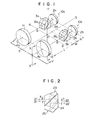
- FIG. 1 is a perspective view showing the principal structure of the optical system employed in the image stabilized optical instrument in accordance with the present invention
- reference numerals la, lb indicate a pair of objectives
- 2a, 2b indicate a pair of eyepieces, respectively.
- a pair of erect prisms 3a and 3b each of which is capable of having its incident light optical axis and emanating light optical axis aligned with each other.
- One objective la, eyepiece 2a and erect prism 3a constitute a first telescopic optical system 10a, and the other objective lb, eyepiece 2b and erect prism 3b constitute second telescopic optical system lOb.
- the first and second telescopic optical systems 10a and 10b constitute an optical system of binoculars.
- a Schmidt's prism As the erect prism which is capable of having its incident light optical axis and emanating light optical axis aligned with each other, a Schmidt's prism, an Abbe's prism or an erect prism of Bauern Fend, for example, can be used.
- the Schmidt's prism is shown in Figure 2.
- the Schmidt's prism comprises two prism blocks 23 and 24.
- the lower portion 25 of the prism block 24 constitutes a roof prism.
- the optical axis of the incident light ray 21 can be aligned with the optical axis of the emanating light ray 22 as shown in Figure 2.
- said objectives la, lb and eyepieces 2a, 2b are fixed to a casing of the optical instrument, and said erect prisms 3a and 3b are mounted on the casing rotatably within a small angular range by means of gimbals which have two pairs of trunnions.
- the axes of rotation of the trunnions 6-6' and 7-7' are intersecting with each other at right angle. If the gimbals are held stationary and fixed to the casing, i.e., if said two erect prisms 3a and 3b are fixed with respect to the casing, the optical system shown in Figure 1 can be regarded as a usual optical system of binoculars.
- optical axes 4a, 4b of the respective telescopic optical systems 10a and 10b with said erect prisms 3a and 3b fixed relative to the casing of the optical instrument are defined as the main optical axes of the optical system.
- the main optical axes 4a and 4b are parallel to each other.
- the gimbals are so oriented that the axis of rotation 6-6' of one pair of trunnions intersects with the main optical axes 4a and 4b at right angle at points A and B, and that the axis of rotation 7-7' of the other pair of trunnions extends in perpendicular to the plane which includes both the main optical axes 4a and 4b and intersects with a theoretical line 5 which is parallel to and equally spaced from the main optical axes 4a and 4b.
- the axes of rotation 6-6' and 7-7' intersect with each other at point O.
- the objectives and the eyepieces respectively comprise a group of lenses having a thickness. Accordingly, exactly, the points A and B should respectively fall on the middle point of the total distance of the sum of the optical distance L from the rear principal plane (nodal plane) of the objective to the incident face of the erect prism, the mechanical distance M from the incident face to the emanating face of the erect prism, and the optical distance N from the emanating face of the erect prism to the front principal plane (nodal plane) of the eyepiece.
- the rear principal plane of the objective referred to in this specification is defined with respect to a focusing point for parallel light rays incident to the objective from left to right in Figure 1.
- the front principal plane of the eyepiece referred to in this specification is defined with respect to a focusing point for parallel rays incident to the eyepiece from right to left in Figure 1.
- the principal planes of the objective and the eyepiece will respectively coincide with the nodal planes thereof, if the objective and eyepiece are in the atmosphere of air.
- the erect prisms 3a and 3b By supporting the erect prisms 3a and 3b on the gimbals so that the erect prisms 3a and 3b are rotatable within a small angular with respect to the casing of the optical system about the axes of rotation 6-6' and 7-7' and by mounting the rotor to the gimbals, the erect prisms 3a and 3b can always take their original positions even if the casing is vibrated or accidentally moved, whereby the angle of the optical axis of the emanating light of the optical system is stabilized and deterioration of the image viewed is prevented as will be described in greater detail hereinbelow.
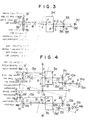
- Figure 3 is a diagramatic representation corresponding to the cross section taken along line X-X' of Figure 1 for illustrating the principle in that the optical axis is stabilized with respect to the vibration in the vertical direction or the direction of the axis 7-7' of the optical system shown in Figure 1.
- an erect prism 34 which has its incident light optical axis and its emanating light optical axis on a common straight line aligned with the optical axis 32 of the objective lens 31.
- light rays incident into the objective lens 31 in parallel to the optical axis 32 emanate from the eyepiece 33 in parallel to the optical axis 32 and are viewed with an eye 37.
- the objective lens 31 is moved to the displaced objective lens 31' and the eyepiece 33 is moved to the displaced eyepiece 33'.
- the principal point g of the objective lens 31 is moved to the displaced principal point g' and the principal point h of the eyepiece 33 is moved to the displaced principal point h'.
- the erect prism 34 is not moved and stays still in its original position by the effect of said gimbals on which it is mounted.
- the light ray 35 parallel to the original optical axis 32 and passing through the displaced principal point g' of the displaced objective lens 31' advances in parallel to the original optical axis 32 after passing through the displaced objective lens 31' and enters the erect prism 34 at an entrance point n apart from the entrance point m of the original optical axis 32 by a distance mn.
- the light ray 35 which enters the erect prism 34 at the entrance point n emanates from the erect prism 34 at an exit point g downwardly apart from an exit point 0 of the original optical axis 32 by a distance Op which is equal to the distance mn based on the effect of the erect prism and advances in parallel to the original optical axis 32 as indicated at 36.
- the bundle parallel to the light ray 35 which enters the displaced objective lens 31' in parallel to the original optical axis 32 is focused at a point S which is on the light ray 36 emanating from the exit point g.
- the point S is on a focal point of the objective 31 including the focal point Q thereof.
- the point S is therefore also on the focal plane of the eyepiece 33.
- the light ray 36 advances in the same direction after passing through the displaced eyepiece 33' as indicated at 36', the light ray 35 parallel to the original optical axis 32 enters the eye 37 in parallel to the original optical axis 32 even if the telescopic optical system of this optical instrument is tilted. Accordingly, the angle of the emanating optical axis is not fluctuated and the image viewed is stabilized even if the telescopic optical system is vibrated.
- the light ray 36 may advance in the same direction after passing through the displaced or tilted eyepiece 33', it is required that the light ray 36 passes through the displaced principal point h' of the displaced eyepiece 33'.
- the distance hh' from the original principal point h of the eyepiece 33 to the displaced principal point h' should be made equal to the distance Op from the exit point 0 of the original optical axis 32 to the exit point p of the light ray 35.
- the position of the point K or the position of the axis of rotation 6-6' about which the optical axis 32 is tilted is selected so that the distance hh' is made equal to the distance Op.
- the point K may simply positioned on the middle point of the mechanical distance from the objective lens 31 to the eyepiece 33 since the distance hh' is equal to the distance from the original principal point a of the objective 31 to the displaced principal point g' as can be seen in Figure 3.
- the erect prism 34 can be located at any position of the optical path of the objective lens, since the distance gg' is always equal to the distance Op.
- the point K or the axis 6-6' of the gimbals should be positioned on the middle point of the total distance of the sum of the optical distance from the objective lens to the incident face of erect prism, the mechanical distance from the incident face the emanating face of the erect prism and the optical distance from the emanating face to the eyepiece.
- Figure 4 is a plan view for explaining the principle in that the image is stabilized with respect to the vibration in the horizontal direction of the direction of the axis 6-6' of the optical system shown :.n Figure 1.
- objective lenses, erect prisms and eyepieces which constitute a pair of telescopic optical systems are indicated at the same reference numerals as those used in Figure 1.
- the optical axis 4a' of the displaced objective lens la' and the displaced eyepiece 2a' is inclined at the angle 6 with respect to the original main optical axis 4a
- the optical axis 4b' of the displaced objective lens lb' and the displaced eyepiece 2b' is inclined at the angle 8 with respect to the original main optical axis 4b.
- an angle w defined by the displaced optical axis 4a' of the displaced eyepiece 2a' and the light ray 15a is represented by a formula wherein f'e represents the focal length of the eyepiece 2a. Therefore, the shortage of the compensation ⁇ for the telescopic optical system 10a can be defined by a formula When ⁇ is small, ⁇ is substantially equal to namely Similarly, the light ray 13b parallel to the original main optical axis 4b of the telescopic optical system 10b and passing through the displaced principal point llb' of the displaced objective lens lb' advances in parallel to the original main optical axis 4b after passing through the displaced objective lens lb' and enters the erect prism 3b at an entrance point n' apart from the entrance point m' of the original main optical axis by a distance The light ray 13b emanates from the erect prism 3b at an exit point t' apart from the exit point S' of the original main optical axis 4b
- the light ray 13b' is refracted by the displaced eyepiece 2b' and enters the eye as indicated at 15b. If the fluctuation of the angle of the emanating light is perfectly compensated when the optical system shown in Figure 4 is tilted by an angle ⁇ ' the light ray 15b should advance in parallel to the original main optical axis 4b and should pass the displaced principal point 12b' of the displaced eyepiece 2b' as indicated at 14b.
- An angle ⁇ ' defined by the light rays 14b and 15b represents shortage of the compensation for the telescopic optical system lOb.
- the shortage of the compensation ⁇ ' for the telescopic optical system 10b can be defined by a formula When ⁇ is small, ⁇ ' is substantially equal to namely Thus, the shortage of compensation remains in both optical axes.
- the direction of shortage of compensation ⁇ is opposite to that of ⁇ '.
- the light rays 15a and 15b are directed inwardly.
- the error in parallelism between the emanating angle of the telescopic optical systems corresponds to the outside error in parallelism between the optical axes of the objective lens systems and its amount is defined as 2 ⁇ /(M-1).
- JIS Japanese Industrial Standard
- M represents the magnification
- K is 1.0 with respect to the error in parallelism in the vertical direction, 1.4 with respect to the outside error, and 2.8 with respect to the inside error.
- the vibration in the vertical direction can be completely compensated. Therefore, there is no problem with respect to the error in parallelism in the vertical direction,
- Figure 6 shows the relationship between the angle of inclination 6 and the error in parallelism with respect to the vibration in the horizontal direction when said 2R/f'e is 3, 4 and 5, and M is lOx.
- said is able to meet the requirement of JIS by properly selecting the value of 2R/f'e.
- the vibration in the vertical direction shares the major portion of the vibration imparted to the optical instrument such as binoculars. Accordingly, it is obvious that in the optical system of this invention the image can be sufficiently stabilized.
- the binoculars of this embodiment has a casing consisting of a casing 101 for mounting thereon gimbals on which a pair of erect prisms 105a and 105b are mounted, a casing 102 for mounting thereon a pair of objectives 116a and 116b, a casing 103 for mounting thereon a pair of eyepieces 118a and 118b and a cover member 104.
- the pair of erect prisms 105a and 105b are fixed to the inner ring 106 of the gimbals.
- the inner ring 106 is rotatably mounted on the outer ring 109 of the gimbals through a pair of bearings 107 and a pair of shafts 108.
- the outer ring 109 is rotatably mounted on the casing 101 through a pair of bearings 110 and a pair of shafts 111 (see Figure 9).
- the inner and outer rings 106 and 109 of the gimbals are rotatable about the respective shafts 108 and 111 which extend perpendicular to each other. Accordingly, the erect prisms 105a and 105b are rotatable relative to the casing 101.
- an electric motor 112 On the inner ring 106 is mounted an electric motor 112 at the intersecting point of the shafts 108 and 111 which motor has a rotor shaft 112a extending perpendicular to the shafts 108 and 111. On opposite ends of the rotor shaft 112a are mounted a pair of rotors 113 and 114.
- the shafts 108 and 111 have a structure which permits flow of an electric current through its interior and the inner ends of the shafts 108 and 111 are in contact with a contact 115a and 115b, respectively, with a small pressure to provide an electric current to the motor 112 without adversely affecting the movement of the gimbals.
- the outer ends of the shafts 108 and 111 are connected to an external power source through a switch 129 and a connector 130 by way of a lead wire (not shown).
- Said pair of objectives 116a and 116b are fixed to the casing 102 which is in turn fixed to the casing 101 at a predetermined position determined by pins 117.
- Said pair of eyepieces 118a and l18b are fixed to the casing 103 which is in turn fixed to the casing 101 at a predetermined position determined by pins 119.
- An annular alminium member 120 is fixed to the rotor 114. Tne alminium member 120 cooperates with a permanent magnetic member 121 fixed to the casing 102 to cause precession due to the effect of eddy-current brake therebetween, thereby permitting the gimbals to move with the casing 102 when the casing 102 is panned slowly to follow the object to be viewed.
- the alminium member 120 tries to keep its position by the inertia of the rotor 114. Accordingly the magnetic member 121 is moved upward relative to the alminium member 120. At this time, the magnetic flux of the magnetic member 121 will pass through only the upper part of the alminium member 120 and the influence of the magnetic flux to the lower part of the alminium member 120 is relatively weakened since the lower part is farther from the magnetic member 121 than the upper portion.
- an eddy-current is induced in the conductor.
- an eddy-current brake is effected upon the moving conductor in the direction to reduce the eddy-current. Therefore, when the casing 102 is swung upward, the alminium member 120 is moved laterally and consequently the rotor shaft 112a follows the casing 102 under the force of precession caused by the effect of the eddy-current brake.
- the binoculars of this embodiment further includes a caging mechanism for holding the gimbals.
- the caging mechanism comprises three claws 123, ring 125 and spring 124 (see Figure 10).
- the three claws 123 hold an annular member 122 provided on the exterior surface of said electric motor l12 under the force of the spring 124.
- Three stud pins 125a fixed to the ring 125 are engaged with recesses formed on the side surface of the claws 123.
- the ring 125 is rotatable and includes a projection 125b.
- FIGs 11 and 12 show binoculars in accordance with another embodiment of the present invention in which the distance between the eyepieces is adjustable.
- the parts similar to those used in the foregoing embodiment are indicated at the same reference numerals used in Figures 7 to 10.
- a pair of eyepieces 118a and 118b are respectively fixed to a pair of housings 155 together with a pair of rhombic prisms 151.
- the housing 155 is rotatably mounted on a casing 152 through a shaft 153 and an annular bearing 154.
- the pair of housings 155 are connected with each other to rotate simultaneously in opposite directions by way of a pair of sector gears 156 integrally formed therewith and a pair of intermediate gears 157 rotatably mounted to the casing 152.
- the axes of the shafts 153 and the bearings 154 are aligned with the optical axes of the objectives 116a and 116b of the respective telescopic optical systems.
- the distance between the optical axes of the eyepieces 118a and 118b can be changed, thereby adjusting the distance between the eyepieces to accomodate the distance between the eyes of the viewer.
Landscapes
- Physics & Mathematics (AREA)
- General Physics & Mathematics (AREA)
- Optics & Photonics (AREA)
- Telescopes (AREA)
- Adjustment Of Camera Lenses (AREA)
- Lens Barrels (AREA)
Applications Claiming Priority (2)
| Application Number | Priority Date | Filing Date | Title |
|---|---|---|---|
| JP88145/77 | 1977-07-22 | ||
| JP8814577A JPS5423554A (en) | 1977-07-22 | 1977-07-22 | Image stabilizing optical device |
Publications (2)
| Publication Number | Publication Date |
|---|---|
| EP0001204A1 true EP0001204A1 (fr) | 1979-04-04 |
| EP0001204B1 EP0001204B1 (fr) | 1981-06-17 |
Family
ID=13934757
Family Applications (1)
| Application Number | Title | Priority Date | Filing Date |
|---|---|---|---|
| EP78100488A Expired EP0001204B1 (fr) | 1977-07-22 | 1978-07-24 | Dispositif gyroscopique de stabilisation des images des appareils binoculaires |
Country Status (4)
| Country | Link |
|---|---|
| US (1) | US4235506A (fr) |
| EP (1) | EP0001204B1 (fr) |
| JP (1) | JPS5423554A (fr) |
| DE (1) | DE2860770D1 (fr) |
Cited By (4)
| Publication number | Priority date | Publication date | Assignee | Title |
|---|---|---|---|---|
| EP0015061A1 (fr) * | 1979-01-20 | 1980-09-03 | Fuji Photo Optical Co., Ltd. | Système optique avec stabilisation d'images |
| FR2485787A1 (fr) * | 1980-06-27 | 1981-12-31 | Etudes Realis Electronique | Appareil stabilisateur de visee optique |
| EP0149118A3 (fr) * | 1979-11-26 | 1985-10-30 | Schwem Instruments | Binoculaire varifocal stabilisé |
| EP0725295A1 (fr) * | 1995-01-19 | 1996-08-07 | Canon Kabushiki Kaisha | Lunette binoculaire ayant des objectifs à distance fixe et à oculaires ajustables |
Families Citing this family (39)
| Publication number | Priority date | Publication date | Assignee | Title |
|---|---|---|---|---|
| JPS57176648A (en) * | 1981-04-24 | 1982-10-30 | Toshiba Corp | Shadow mask electrode for color picture tube |
| DE3628480A1 (de) * | 1985-08-23 | 1987-03-05 | Canon Kk | Verfahren und vorrichtung zur kompensation einer bewegung eines bildes |
| GB8723209D0 (en) * | 1987-10-02 | 1987-11-04 | Emi Plc Thorn | Optical image rotators |
| JPH0259165U (fr) * | 1988-10-20 | 1990-04-27 | ||
| DE3843776A1 (de) * | 1988-12-24 | 1990-07-05 | Zeiss Carl Fa | Fernrohr mit bildfeldstabilisierung |
| GB2235788A (en) * | 1989-09-06 | 1991-03-13 | Asahi Optical Co Ltd | Image stabilizing apparatus |
| DE3933255C2 (de) * | 1989-10-05 | 1995-12-21 | Knoll Dieter B Dr | Richtungsstabilisiertes Fernrohr |
| JP3044106B2 (ja) * | 1991-10-09 | 2000-05-22 | キヤノン株式会社 | 像ぶれ防止機能付カメラ |
| JPH06310547A (ja) * | 1993-02-25 | 1994-11-04 | Mitsubishi Electric Corp | 半導体装置及びその製造方法 |
| US5672862A (en) * | 1993-07-30 | 1997-09-30 | Canon Kabushiki Kaisha | Optical apparatus having image shake preventing function |
| JP3263236B2 (ja) * | 1994-04-20 | 2002-03-04 | 富士写真光機株式会社 | 電池ボックス |
| JP2941647B2 (ja) * | 1994-05-10 | 1999-08-25 | 富士写真光機株式会社 | 像安定光学装置 |
| US5539575A (en) * | 1994-05-10 | 1996-07-23 | Fuji Photo Optical Co., Ltd. | Image stabilized optical system |
| JPH1020213A (ja) * | 1996-07-03 | 1998-01-23 | Nikon Corp | 手振れ補正機構付き双眼鏡 |
| JP3451578B2 (ja) * | 1996-10-01 | 2003-09-29 | 富士写真光機株式会社 | 像安定化装置 |
| US6067194A (en) * | 1997-09-29 | 2000-05-23 | Leica Camera Ag | Image stabilizing instrument |
| JP3765463B2 (ja) * | 1999-09-08 | 2006-04-12 | フジノン株式会社 | 像安定化装置 |
| SE0001816L (sv) * | 2000-05-17 | 2001-10-22 | Stable Eyes Ab | Variabelt okularavstånd för en bildstabiliserande dubbelkikare |
| JP2003222802A (ja) * | 2002-01-29 | 2003-08-08 | Fuji Photo Optical Co Ltd | 観察用光学機器 |
| DE10251933B4 (de) * | 2002-11-08 | 2006-12-14 | Ludwig-Maximilians-Universität München (Körperschaft des öffentlichen Rechts) | Aufnahmevorrichtung für die kopfgestützte Bilderfassung und Verfahren zur Steuerung der Aufnahmevorrichtung |
| RU2231098C1 (ru) * | 2003-08-07 | 2004-06-20 | Фроимсон Игорь Михайлович | Оптическая система со стабилизацией изображения |
| DE102005027870B4 (de) * | 2005-06-09 | 2008-11-27 | Carl Zeiss Sports Optics Gmbh | Fernglas |
| DE102005027867A1 (de) * | 2005-06-09 | 2006-12-14 | Hensoldt Ag | Fernglas |
| WO2008020967A2 (fr) * | 2006-08-08 | 2008-02-21 | Peak Biosciences, Inc. | Cathéter et arrangement pour une thérapie anti-cancer |
| WO2008115511A1 (fr) * | 2007-03-20 | 2008-09-25 | Peak Biosciences, Inc. | Méthode pour l'administration thérapeutique de radionucléosides |
| WO2008140808A1 (fr) * | 2007-05-10 | 2008-11-20 | Peak Biosciences, Inc. | Procédés d'administration d'agents radiothérapeutiques |
| DE102008003414A1 (de) * | 2008-01-08 | 2009-07-09 | Carl Zeiss Sports Optics Gmbh | Binokulares Fernglas |
| RU2442199C1 (ru) * | 2010-06-04 | 2012-02-10 | Открытое акционерное общество "Красногорский завод им. С.А. Зверева" | Наблюдательный прибор со стабилизацией и цифровой фоторегистрацией |
| DE102012200519A1 (de) | 2012-01-13 | 2013-07-18 | Carl Zeiss Sports Optics Gmbh | Optisches System zur Abbildung eines Objekts |
| DE102012000859B4 (de) | 2012-01-13 | 2021-05-06 | Carl Zeiss Ag | Binokulare fernoptische Vorrichtung mit Bildstabilisierung |
| ES2906374T3 (es) * | 2012-07-13 | 2022-04-18 | Steris Instrument Man Services Inc | Sistema de endoscopio estereoscópico |
| JP6187933B2 (ja) | 2012-10-01 | 2017-08-30 | 鎌倉光機株式会社 | 像安定化装置 |
| DE102013200316A1 (de) * | 2013-01-11 | 2014-07-17 | Carl Zeiss Sports Optics Gmbh | Optisches System zur Abbildung eines Objekts |
| JP6151622B2 (ja) * | 2013-10-16 | 2017-06-21 | 鎌倉光機株式会社 | 像安定化装置 |
| US9395551B2 (en) | 2013-04-24 | 2016-07-19 | Kamakura Koki Co., Ltd. | Optical image stabilizer |
| JP2014232278A (ja) * | 2013-05-30 | 2014-12-11 | 富士フイルム株式会社 | ブレ補正装置及び観察装置 |
| JP6278721B2 (ja) | 2014-01-31 | 2018-02-14 | 鎌倉光機株式会社 | 像安定化装置 |
| DE102019200309A1 (de) | 2019-01-11 | 2020-07-16 | Carl Zeiss Ag | Optisches System zur Abbildung eines Objekts sowie Verfahren zum Betrieb des optischen Systems |
| WO2023218819A1 (fr) * | 2022-05-13 | 2023-11-16 | 株式会社ニコンビジョン | Système optique d'observation et dispositif optique |
Citations (7)
| Publication number | Priority date | Publication date | Assignee | Title |
|---|---|---|---|---|
| US2939363A (en) * | 1955-10-20 | 1960-06-07 | J W Fecker Inc | Optical sighting device |
| GB1093131A (en) * | 1963-07-24 | 1967-11-29 | Barr & Stroud Ltd | Stabilised telescope |
| US3558211A (en) * | 1968-05-08 | 1971-01-26 | Baird Atomic Inc | Mechanical means for inertially stabilizing optical system against image motion |
| DE2353101A1 (de) * | 1972-10-25 | 1974-05-09 | Fraser Volpe Corp | Fernoptisches geraet mit bildstabilisierung |
| DE2419532A1 (de) * | 1973-05-12 | 1974-11-28 | Fuji Photo Optical Co Ltd | Vorrichtung zur stabilisierung einer optischen abbildung |
| DE2166249B2 (de) * | 1971-03-29 | 1975-07-24 | Anschuetz & Co Gmbh, 2300 Kiel | Allseitig kippbare Lagerung eines optischen Geräts auf einem Träger |
| DE2239426B2 (de) * | 1972-08-10 | 1976-07-29 | Anschütz & Co GmbH, 2300 Kiel | Allseitig kippbare lagerung eines optischen geraets auf einem traeger |
Family Cites Families (7)
| Publication number | Priority date | Publication date | Assignee | Title |
|---|---|---|---|---|
| US2829557A (en) * | 1950-01-17 | 1958-04-08 | Jensen Homer | Stabilized optical sighting device |
| US3006197A (en) * | 1960-01-18 | 1961-10-31 | Kenyon Lab Inc | Stabilizing instrument |
| US3608996A (en) * | 1968-09-04 | 1971-09-28 | Optigon Res & Dev Corp | Optical path detour stabilization system |
| US3608995A (en) * | 1968-09-04 | 1971-09-28 | Optigon Res & Dev Corp | Intermediate optical processing stabilizer |
| US3610764A (en) * | 1970-08-27 | 1971-10-05 | Zeiss Jena Veb Carl | Automatic leveling telescope including a reversible two-sided pendulum mirror and a focusing prism |
| US3728948A (en) * | 1970-12-28 | 1973-04-24 | Dynasciences Corp | Image motion compensation mechanism |
| JPS5311381B2 (fr) * | 1973-05-18 | 1978-04-21 |
-
1977
- 1977-07-22 JP JP8814577A patent/JPS5423554A/ja active Granted
-
1978
- 1978-07-20 US US05/926,382 patent/US4235506A/en not_active Expired - Lifetime
- 1978-07-24 DE DE7878100488T patent/DE2860770D1/de not_active Expired
- 1978-07-24 EP EP78100488A patent/EP0001204B1/fr not_active Expired
Patent Citations (7)
| Publication number | Priority date | Publication date | Assignee | Title |
|---|---|---|---|---|
| US2939363A (en) * | 1955-10-20 | 1960-06-07 | J W Fecker Inc | Optical sighting device |
| GB1093131A (en) * | 1963-07-24 | 1967-11-29 | Barr & Stroud Ltd | Stabilised telescope |
| US3558211A (en) * | 1968-05-08 | 1971-01-26 | Baird Atomic Inc | Mechanical means for inertially stabilizing optical system against image motion |
| DE2166249B2 (de) * | 1971-03-29 | 1975-07-24 | Anschuetz & Co Gmbh, 2300 Kiel | Allseitig kippbare Lagerung eines optischen Geräts auf einem Träger |
| DE2239426B2 (de) * | 1972-08-10 | 1976-07-29 | Anschütz & Co GmbH, 2300 Kiel | Allseitig kippbare lagerung eines optischen geraets auf einem traeger |
| DE2353101A1 (de) * | 1972-10-25 | 1974-05-09 | Fraser Volpe Corp | Fernoptisches geraet mit bildstabilisierung |
| DE2419532A1 (de) * | 1973-05-12 | 1974-11-28 | Fuji Photo Optical Co Ltd | Vorrichtung zur stabilisierung einer optischen abbildung |
Cited By (4)
| Publication number | Priority date | Publication date | Assignee | Title |
|---|---|---|---|---|
| EP0015061A1 (fr) * | 1979-01-20 | 1980-09-03 | Fuji Photo Optical Co., Ltd. | Système optique avec stabilisation d'images |
| EP0149118A3 (fr) * | 1979-11-26 | 1985-10-30 | Schwem Instruments | Binoculaire varifocal stabilisé |
| FR2485787A1 (fr) * | 1980-06-27 | 1981-12-31 | Etudes Realis Electronique | Appareil stabilisateur de visee optique |
| EP0725295A1 (fr) * | 1995-01-19 | 1996-08-07 | Canon Kabushiki Kaisha | Lunette binoculaire ayant des objectifs à distance fixe et à oculaires ajustables |
Also Published As
| Publication number | Publication date |
|---|---|
| JPS5737852B2 (fr) | 1982-08-12 |
| EP0001204B1 (fr) | 1981-06-17 |
| JPS5423554A (en) | 1979-02-22 |
| DE2860770D1 (en) | 1981-09-24 |
| US4235506A (en) | 1980-11-25 |
Similar Documents
| Publication | Publication Date | Title |
|---|---|---|
| US4235506A (en) | Image stabilized optical system | |
| EP0015061B1 (fr) | Système optique avec stabilisation d'images | |
| US4615590A (en) | Optically stabilized camera lens system | |
| US5381264A (en) | Multiple field of view sensor lens assembly | |
| US3728948A (en) | Image motion compensation mechanism | |
| US4417788A (en) | Stabilized zoom binocular | |
| US3953106A (en) | Image stabilizing optical system | |
| US3591250A (en) | Mechanical image motion stabilizer with rotation rate comparison system | |
| US3531176A (en) | Multiple telescope stabilizing optical system | |
| US3762795A (en) | Observation instrument with panoramic vision | |
| US3468595A (en) | Optical stabilization by reflecting means | |
| US3608995A (en) | Intermediate optical processing stabilizer | |
| US6538812B1 (en) | Telescope and binoculars | |
| JP4042170B2 (ja) | 防振望遠鏡 | |
| US4260218A (en) | Stabilized optical system with off-axis stabilizer | |
| US6362918B1 (en) | Compact keplerian telescope | |
| US3608997A (en) | Focal plane stabilization system | |
| US4542962A (en) | Image-stabilized optical instrument, such as telescope and cameras | |
| EP0809780B1 (fr) | Telescope keplerien compact | |
| US3608996A (en) | Optical path detour stabilization system | |
| US3881803A (en) | Stabilized optical viewing device | |
| JPH0214017Y2 (fr) | ||
| JPH11295774A (ja) | 防振機構を備えた双眼鏡 | |
| US4249792A (en) | Optical observation instrument with fiber optic image stabilizer | |
| GB2093213A (en) | Optical Radiation Receiving Apparatus |
Legal Events
| Date | Code | Title | Description |
|---|---|---|---|
| PUAI | Public reference made under article 153(3) epc to a published international application that has entered the european phase |
Free format text: ORIGINAL CODE: 0009012 |
|
| AK | Designated contracting states |
Designated state(s): DE FR GB SE |
|
| 17P | Request for examination filed | ||
| GRAA | (expected) grant |
Free format text: ORIGINAL CODE: 0009210 |
|
| AK | Designated contracting states |
Designated state(s): DE FR GB SE |
|
| REF | Corresponds to: |
Ref document number: 2860770 Country of ref document: DE Date of ref document: 19810924 |
|
| PGFP | Annual fee paid to national office [announced via postgrant information from national office to epo] |
Ref country code: FR Payment date: 19840621 Year of fee payment: 7 |
|
| PGFP | Annual fee paid to national office [announced via postgrant information from national office to epo] |
Ref country code: DE Payment date: 19840723 Year of fee payment: 7 |
|
| PGFP | Annual fee paid to national office [announced via postgrant information from national office to epo] |
Ref country code: SE Payment date: 19840930 Year of fee payment: 7 |
|
| PG25 | Lapsed in a contracting state [announced via postgrant information from national office to epo] |
Ref country code: SE Effective date: 19870725 |
|
| PG25 | Lapsed in a contracting state [announced via postgrant information from national office to epo] |
Ref country code: FR Free format text: LAPSE BECAUSE OF NON-PAYMENT OF DUE FEES Effective date: 19880331 |
|
| PG25 | Lapsed in a contracting state [announced via postgrant information from national office to epo] |
Ref country code: DE Effective date: 19880401 |
|
| GBPC | Gb: european patent ceased through non-payment of renewal fee | ||
| REG | Reference to a national code |
Ref country code: FR Ref legal event code: ST |
|
| PG25 | Lapsed in a contracting state [announced via postgrant information from national office to epo] |
Ref country code: GB Free format text: LAPSE BECAUSE OF NON-PAYMENT OF DUE FEES Effective date: 19881117 |
|
| EUG | Se: european patent has lapsed |
Ref document number: 78100488.2 Effective date: 19880713 |
|
| PLBE | No opposition filed within time limit |
Free format text: ORIGINAL CODE: 0009261 |
|
| STAA | Information on the status of an ep patent application or granted ep patent |
Free format text: STATUS: NO OPPOSITION FILED WITHIN TIME LIMIT |