EP0003936B1 - Automatische Vorrichtung zum Wägen und Entleeren eines in einem mit einem Deckel versehenen Behälter enthaltenen Produktes - Google Patents
Automatische Vorrichtung zum Wägen und Entleeren eines in einem mit einem Deckel versehenen Behälter enthaltenen Produktes Download PDFInfo
- Publication number
- EP0003936B1 EP0003936B1 EP79400114A EP79400114A EP0003936B1 EP 0003936 B1 EP0003936 B1 EP 0003936B1 EP 79400114 A EP79400114 A EP 79400114A EP 79400114 A EP79400114 A EP 79400114A EP 0003936 B1 EP0003936 B1 EP 0003936B1
- Authority
- EP
- European Patent Office
- Prior art keywords
- container
- cover
- weighing
- jack
- manipulating
- Prior art date
- Legal status (The legal status is an assumption and is not a legal conclusion. Google has not performed a legal analysis and makes no representation as to the accuracy of the status listed.)
- Expired
Links
- 238000005303 weighing Methods 0.000 title claims description 52
- 238000007789 sealing Methods 0.000 claims 2
- 238000006073 displacement reaction Methods 0.000 claims 1
- 230000001105 regulatory effect Effects 0.000 claims 1
- 230000000712 assembly Effects 0.000 description 4
- 238000000429 assembly Methods 0.000 description 4
- 238000009434 installation Methods 0.000 description 2
- 238000011109 contamination Methods 0.000 description 1
- 238000012423 maintenance Methods 0.000 description 1
- 238000000034 method Methods 0.000 description 1
- 230000002285 radioactive effect Effects 0.000 description 1
- 230000000630 rising effect Effects 0.000 description 1
- 230000032258 transport Effects 0.000 description 1
Images


Classifications
-
- G—PHYSICS
- G21—NUCLEAR PHYSICS; NUCLEAR ENGINEERING
- G21F—PROTECTION AGAINST X-RADIATION, GAMMA RADIATION, CORPUSCULAR RADIATION OR PARTICLE BOMBARDMENT; TREATING RADIOACTIVELY CONTAMINATED MATERIAL; DECONTAMINATION ARRANGEMENTS THEREFOR
- G21F7/00—Shielded cells or rooms
- G21F7/06—Structural combination with remotely-controlled apparatus, e.g. with manipulators
-
- B—PERFORMING OPERATIONS; TRANSPORTING
- B25—HAND TOOLS; PORTABLE POWER-DRIVEN TOOLS; MANIPULATORS
- B25J—MANIPULATORS; CHAMBERS PROVIDED WITH MANIPULATION DEVICES
- B25J21/00—Chambers provided with manipulation devices
Definitions
- the present invention which results from the work of Messrs Georges BERGER of the SIMON Fromme Establishments, and Jacques SALOM of COGEMA, relates to an automatic device for weighing and emptying a product contained in a container provided with a lid.
- This device can be used in all cases where the product contained in the container presents dangers for the personnel responsible for handling it. This is common, for example, in nuclear or chemical installations.
- This manipulation often consists, on the one hand, of weighing the product contained inside the container, on the other hand, emptying this product into a treatment tank. Generally, to avoid any accident, this manipulation is carried out remotely, inside a biological enclosure, so as to avoid any risk of contamination of the personnel responsible for the manipulation.
- the handling consists, on the one hand, in weighing the product contained in the container and, on the other hand in emptying this product in a tank, the operator must first of all bring the product contained in a container on the pan of a scale located inside the enclosure; he must then bring the container above a drain pan to pour the product into it, then bring this empty container back onto the scale pan in order to know the weight of the product that was contained inside the container, thanks to a double weighing method.
- the manipulations carried out using such devices are long and delicate.
- the operator even if he has sophisticated articulated devices can not work as quickly as if he acted directly by hand; moreover, due to this remote action, handling incidents may arise, such as for example the spilling of the product outside the container, difficulties in removing the lid placed on the container or in replacing this lid that the operator may inadvertently leak out next to the container.
- the containers In nuclear installations, the containers generally contain radioactive products. These products and this container are often very heavy and it is then even more difficult for an operator located at a distance to move these containers, remove their lid, empty them, weigh the product they contain etc.
- the present invention aims to remedy these drawbacks and in particular to provide an automatic device for weighing and emptying a product contained in a container with a lid.
- This fully automatic device avoids any handling error and allows the weighing and emptying of dangerous and heavy products contained in very heavy containers.
- the means making it possible to grip the container in order to bring it onto the weighing device and to place it opposite the handling assembly of the cover comprise a gripping cylinder provided with gripping means and controlled by the synchronization means, so that the container is grasped on the handling area, brought to the weighing area before removing the cover and draining the product, then brought back from the weighing area to the handling area after emptying of product and closure of the container by the lid.
- the gripping cylinder is mounted on the frame associated with a vertical jack capable of lifting the frame before weighing the full container, lowering the frame to place the container on the weighing device, lift the frame after weighing, lower the frame before fitting into the handling assembly so that the cover is removed and before fitting into the drain assembly, then lift the frame again after emptying and closing the container by the cover, to lower the frame when the container is facing the weighing device, to lift the frame after weighing the empty container, to lower the frame when the container is returned to the handling area, this gripping jack being controlled by said synchronization means.
- This device allows the weighing and automatic emptying of a product contained in a container 1 provided with a cover 2.
- This device comprises means 3 for bringing the container to a handling area 4. These means can be constituted, for example , by a carriage which can be circular on rails 5. The carriage as well as the various means which will be described later, are contained inside an enclosure 6, for example biological.
- Means 7 are provided for grasping the container, for bringing it to a weighing device 8, and for placing it opposite a mounting 9 allowing the lid 2 to be manipulated.
- the device also comprises means 10 for placing the container in the assembly 9 for handling the cover and for engaging it in an assembly 11 for draining the product.
- Synchronization means 12 are provided for controlling relays acting on the above means and assemblies in a first direction, so that the container is supported brought to the handling area 4 by the carriage 3, then gripped by the means 7 so to be brought to the weighing area 8, then placed in the handling assembly 9 where the cover is removed and then engaged in the product drain assembly 11. These synchronization means then control the above means and assemblies in a second direction reverse of the previous one so that the empty container is released from the drain assembly 11, then replaced in the lid handling assembly 9 allowing the lid to be replaced on the container, then for the container is returned to the weighing device 8 and brought back to the starting point on the trolley 3.
- the means 7 which make it possible to grip the container to bring it onto the weighing device 8 and to place it opposite the handling assembly 9 of the cover 2, comprise a gripping cylinder 13 which is provided at its free end with gripping means 14 which have, for example, the shape of an open C.
- the synchronization means 12 control the jack 13 so that the latter is retracted into position 15; the container then comes to the weighing device 8.
- This gripping cylinder 13 is mounted on a frame 16 which is associated with a vertical cylinder 17; this vertical jack allows the frame to be lifted when the container is grasped on the carriage 3 and then brought above the weighing device 8.
- the vertical jack 17 also makes it possible to lower the frame to place the container on the weighing device .
- the frame is then lifted after the container containing the product has been weighed, then lowered again before the container is placed in the handling assembly of the cover.
- the frame 16 is also associated with a horizontal cylinder 18. This horizontal cylinder makes it possible to pivot the frame 16 about the axis 19. This pivoting of the frame brings the container into position 20, opposite the assembly 9 for handling the cover. 2.
- the vertical jack 17 lowers the frame 16 so that the container can be engaged in the assembly for handling the cover.
- the means 10 which make it possible to place the container in the assembly 9 for handling the cover and to engage this container in the assembly 11 for emptying the products, comprise a jack provided with gripping means which will be described in detail below.
- This jack and these gripping means make it possible to grasp the container in position 20 when the jack 13 has been released to return to position 15.
- the container is then brought into the means 9 for handling the cover so that the cover is removed. .
- the means 10 then engage the container in the product drain assembly 11. When the product is drained, the means 10 bring the container back to the lid handling assembly so that the container is closed.
- the gripping cylinder 13 then takes the container back in position 20 to bring it back to the weighing area 8.
- the removed cover has been shown at 21 and the empty container 1 has been shown in position 22.
- the synchronization means 12 which have not been shown in detail are constituted in a known manner, for example by timers acting on electromechanical relays linked to each of the cylinders of the dif the various means of the device. These relays control the extension or removal of the cylinders according to the handling to be performed.
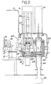
- FIG. 2 there is shown schematically on the one hand the means 9 for handling the cover, on the other hand, the means 11 which make it possible to empty the product into a tank 36.
- the frame 16 pivoting around the axis 19 so as to come to occupy position 20, opposite the assembly for handling the cover and then lowering or rising thanks to the jack 17.
- the weighing apparatus 8 on which the container rests either before emptying or after emptying the product.
- the means 10 which allow the container to be brought into the lid handling assembly are shown in more detail in this figure.
- the means 9 for handling the cover comprise a base 25 associated with a first cylinder 26 which holds the container on the base 25 by means of arms 27.
- This base is also associated with a second cylinder 28 and gripping means 29, adapted the shape of the cover and which allow either to remove or replace the cover 2 on the container 1.
- Another cylinder 30 has been shown in the figure; this jack raises the base 25 so as to strengthen the action of the jack 26 to ensure better maintenance of the container.
- the drain assembly 11 comprises a base 31 associated with a jack 32 which, by lifting, keeps the container in the drain assembly.
- This base is also associated with rotation means 33, with a horizontal axis, which rotate the container around this axis.
- the rotation means 33 turn the container over so that its opening is directed upwards.
- a suction system 35 which can be lowered and then raised, sucks the product which could have remained in the container after emptying. After this suction, the jack 23 brings the container back into the lid handling means where the container is closed.
- this figure has not shown the synchronization means and the relays acting on the various jacks.
- FIG. 3 With reference to fig. 3, there is shown the means 9 for handling the cover and the means 11 for draining the product, at the moment when the cover 2 has been removed and the container is turned over so that the product is discharged by the intermediate the chute 34 in the tank 36.
- the gripping means 24 located at the end of the jack 23 can pivot around the jack 23 when the container is turned over to empty the product.
- the synchronization means 12, the relays and the various jacks operate in the following manner: when the carriage 3 brings the container 1 opposite the gripping means 14, the vertical jack 17 lifts the container so as to disengage it from the carriage. The jack 13 retracts and the container is then brought above the weighing device 8, in position 15. The frame 16 is then lifted by the vertical jack 17 so as to disengage the container from the weighing area then this frame pivots around the axis 19 under the action of the jack 18, the container then occupies the position 20, opposite the means for handling the cover 9. The frame 16 then lowers thanks to the vertical jack 17, so that the container is placed on the base 25 of the handling means 9. The frame then pivots in the opposite direction under the action of the jack 18, the gripping means 14 again occupy the position 15.
- the container is then released and can be taken up by the means 10 which then make it possible to bring this.
- container in the handling means 9 where it will be held in place thanks to the jacks 26 and 30 and where the cover 2 will be removed.
- the jack 23 and the gripping means 24 make it possible to engage the container in the emptying means 11.
- the container is held in position in these emptying means, thanks to the base 31 lifted by the jack 32
- the container is then inverted by means of rotation 33 and the product is drained; then the container is inverted by these same means 33, so that its opening is directed upwards.
- the jack 23 brings the container back into the means 9 for handling the cover; the container is held in these handling means by the jacks 30 and 27; the jack 28 is lowered and the cover 2 thus closes the container 1.
- the jacks 27, 28 and 30 are raised and the container is released from the handling means 9.
- the base 16 then pivots in the opposite direction in position 20, around the axis 19 thanks to the cylinder 18, so that the gripping means 14 again come to grip the container 1.
- the cylinder 23 is released and the vertical cylinder 19 lifts the container; the frame 16 pivots so as to bring the jack 13 back into position 15, above the platform of the weighing apparatus 8.
- the frame 16 is then lowered using the vertical jack 17 and the empty container is thus placed on the weighing device 8.
- the container having been weighed full then empty, it is easy to know the quantity of product that it contained.
- the frame 16 is lifted thanks to the jack 17, then the jack 13 lengthens so that the container is placed above the carriage 3.
- the frame 16 is lowered by means of the jack 17 and the container is placed on the carriage 3.
- the carriage is then brought back to release the empty container to the outside of the enclosure where it can again be filled or handled.
- the weighing device 8 can of course be provided with automatic means for locating the different weighings.
- this figure has not shown the synchronization means and the relays controlling the various jacks.
- the device of the invention does indeed achieve the goals mentioned above. It allows automatic weighing, on the one hand, and, on the other hand, emptying of a container containing a contaminated product which is dangerous for an operator. This manipulation is carried out inside a biological protection enclosure and the device which comprises jacks allows handling of very heavy containers and containing also very heavy products.
Landscapes
- Engineering & Computer Science (AREA)
- Robotics (AREA)
- Mechanical Engineering (AREA)
- Physics & Mathematics (AREA)
- General Engineering & Computer Science (AREA)
- High Energy & Nuclear Physics (AREA)
- Control And Other Processes For Unpacking Of Materials (AREA)
- Devices For Opening Bottles Or Cans (AREA)
- Weight Measurement For Supplying Or Discharging Of Specified Amounts Of Material (AREA)
Claims (9)
Applications Claiming Priority (2)
| Application Number | Priority Date | Filing Date | Title |
|---|---|---|---|
| FR7805866A FR2418702A1 (fr) | 1978-03-01 | 1978-03-01 | Dispositif automatique de pesee et de vidange d'un produit contenu dans un recipient muni d'un couvercle |
| FR7805866 | 1978-03-01 |
Publications (2)
| Publication Number | Publication Date |
|---|---|
| EP0003936A1 EP0003936A1 (de) | 1979-09-05 |
| EP0003936B1 true EP0003936B1 (de) | 1981-05-13 |
Family
ID=9205209
Family Applications (1)
| Application Number | Title | Priority Date | Filing Date |
|---|---|---|---|
| EP79400114A Expired EP0003936B1 (de) | 1978-03-01 | 1979-02-26 | Automatische Vorrichtung zum Wägen und Entleeren eines in einem mit einem Deckel versehenen Behälter enthaltenen Produktes |
Country Status (5)
| Country | Link |
|---|---|
| US (1) | US4228864A (de) |
| EP (1) | EP0003936B1 (de) |
| JP (1) | JPS5926433B2 (de) |
| DE (1) | DE2960332D1 (de) |
| FR (1) | FR2418702A1 (de) |
Families Citing this family (20)
| Publication number | Priority date | Publication date | Assignee | Title |
|---|---|---|---|---|
| NL8300586A (nl) * | 1983-02-16 | 1984-09-17 | Dow Chemical Nederland | Inrichting en werkwijze voor het automatisch hanteren van monsters. |
| DE3440277C1 (de) * | 1984-11-03 | 1986-05-22 | Siempelkamp Gießerei GmbH & Co, 4150 Krefeld | Verfahren zum Einbringen von radioaktiven Abfaellen in einen Schmelzofen und Vorrichtung zur Durchfuehrung des Verfahrens |
| DE3447648C2 (de) * | 1984-12-28 | 1986-12-11 | Garbade, Rolf, 2804 Lilienthal | Verfahren und Vorrichtung zur gewichtsmäßigen Erfassung von Material, vorzugsweise Müll, bei der Entleerung in ein Sammelfahrzeug |
| US4775279A (en) * | 1985-12-11 | 1988-10-04 | American Tech Manufacturing, Inc. | Method and apparatus for loading/unloading dip devices |
| US4764079A (en) * | 1986-06-27 | 1988-08-16 | American Tech Manufacturing, Inc. | Method and apparatus for handling dip devices |
| US4749541A (en) * | 1986-12-05 | 1988-06-07 | Westinghouse Electric Corp. | Position sensing mechanism for a nuclear fuel transfer system |
| DE3814938A1 (de) * | 1988-05-03 | 1989-11-16 | Wiederaufarbeitung Von Kernbre | Andockvorrichtung zum anschliessen eines transport- und/oder lagerbehaelters an einen radioaktiv belasteten arbeitsraum |
| US4988255A (en) * | 1989-02-22 | 1991-01-29 | The Upjohn Company | Unpackaging machine |
| US5092413A (en) * | 1990-12-17 | 1992-03-03 | Andrews James S | Method and apparatus for high speed weigh fill |
| GB9304965D0 (en) * | 1993-03-11 | 1993-04-28 | British Nuclear Fuels Plc | Weighing system |
| FR2711805B1 (fr) * | 1993-10-22 | 1995-12-08 | Cogema | Chaîne d'analyses automatisée. |
| US5531964A (en) * | 1994-10-25 | 1996-07-02 | Compagnie Generale Des Matieres Nucleaires | Automated analysis chain |
| FR2747780B1 (fr) * | 1996-04-22 | 1998-06-05 | Cogema | Dispositif de prelevement d'echantillons liquides nocifs, notamment charges de particules solides |
| FR2776389B1 (fr) * | 1998-03-20 | 2000-06-16 | Fondation Jean Dausset Ceph | Dispositif automatique de realisation d'echantillons en vue de la mise en oeuvre de reactions chimiques ou biologiques en milieu liquide |
| US6448564B1 (en) | 2000-05-30 | 2002-09-10 | Gtsd Sub Iii | Apparatus, methods, and systems for assaying materials |
| US6705827B2 (en) * | 2000-08-25 | 2004-03-16 | Aagrinomics, Llc | Robotic seed-handling apparatus and methods |
| US6585828B1 (en) * | 2000-09-26 | 2003-07-01 | Applied Materials, Inc. | Process chamber lid service system |
| US6892512B2 (en) * | 2002-08-07 | 2005-05-17 | Medco Health Solutions, Inc. | Automated prescription filling system/method with automated labeling and packaging system/method automated order consolidation system/method |
| US9689782B2 (en) | 2012-07-19 | 2017-06-27 | Monsanto Technology Llc | Small object distribution automation |
| CN114988109B (zh) * | 2022-06-24 | 2022-11-11 | 东风河西(武汉)顶饰系统有限公司 | 一种汽车顶棚自动上料装置 |
Family Cites Families (10)
| Publication number | Priority date | Publication date | Assignee | Title |
|---|---|---|---|---|
| US2641459A (en) * | 1949-03-15 | 1953-06-09 | Mchale | Weighing apparatus |
| US3090480A (en) * | 1952-10-29 | 1963-05-21 | William D Egnor | Sample can handling mechanism |
| US2990073A (en) * | 1959-03-04 | 1961-06-27 | Andre F Textor | Machine for conveying and dumping milk cans |
| US3252559A (en) * | 1962-03-13 | 1966-05-24 | Jr George E Von Gal | Article transfer device |
| US3263842A (en) * | 1963-08-12 | 1966-08-02 | Schenley Distillers Co Inc | Case dumper |
| FR1543264A (fr) * | 1967-07-20 | 1968-10-25 | Commissariat Energie Atomique | Appareil pour le retrait ou la mise en place d'un couvercle amovible |
| US3539029A (en) * | 1967-11-13 | 1970-11-10 | Machinery Co Const | Weighing apparatus with hydraulic cylinder pivot means for emptying into mixing drum |
| GB1443789A (en) * | 1973-11-28 | 1976-07-28 | Monsanto Ltd | Apparatus for measuring specific gravity |
| US3910364A (en) * | 1975-01-20 | 1975-10-07 | Royal Industries | Trailer dumping and weighing system |
| US4024962A (en) * | 1975-10-06 | 1977-05-24 | The Mcdowell-Wellman Engineering Company | Car dumper scale |
-
1978
- 1978-03-01 FR FR7805866A patent/FR2418702A1/fr active Granted
-
1979
- 1979-02-26 DE DE7979400114T patent/DE2960332D1/de not_active Expired
- 1979-02-26 EP EP79400114A patent/EP0003936B1/de not_active Expired
- 1979-02-27 US US06/015,623 patent/US4228864A/en not_active Expired - Lifetime
- 1979-02-28 JP JP54023295A patent/JPS5926433B2/ja not_active Expired
Also Published As
| Publication number | Publication date |
|---|---|
| JPS55465A (en) | 1980-01-05 |
| US4228864A (en) | 1980-10-21 |
| FR2418702B1 (de) | 1980-10-17 |
| EP0003936A1 (de) | 1979-09-05 |
| DE2960332D1 (en) | 1981-08-20 |
| JPS5926433B2 (ja) | 1984-06-27 |
| FR2418702A1 (fr) | 1979-09-28 |
Similar Documents
| Publication | Publication Date | Title |
|---|---|---|
| EP0003936B1 (de) | Automatische Vorrichtung zum Wägen und Entleeren eines in einem mit einem Deckel versehenen Behälter enthaltenen Produktes | |
| JPS606179A (ja) | 食肉柔軟化装置 | |
| FR2459768A1 (fr) | Dispositif de verrouillage des bacs a dechets sur un vehicule de collecte par basculement de ces bacs | |
| FR2957337A1 (fr) | Machine de retournement automatique d'objets conditionnes sur claies | |
| CN112313151A (zh) | 一种从由托盘构成的相应支撑元件中提取药物容器为瓶子的装置 | |
| EP0033670B1 (de) | Verfahren und Vorrichtung zum Ausformen von Weichkäse | |
| EP0015848B1 (de) | Transportvorrichtung für die Behandlung von Werkstücken in einer Bearbeitungsanlage | |
| EP0425331B1 (de) | Vorrichtung zum Entleeren durch Untertauchen von Kästen, welche schwimmfähige Gegenstände enthalten, insbesondere Obst | |
| FR2459000A1 (fr) | Machine a demouler, en particulier les jambons | |
| US2566598A (en) | Surface supported device for gripping a receptacle and removing the closure and having a single operator | |
| EP1406684A1 (de) | Verfahren zur sicherung der verfolgung von blutkonserven | |
| EP0653486B1 (de) | Vorrichtung, die die Behandlung des Weines nach der Champagner-Methode erlaubt | |
| EP0138653B1 (de) | Automatische Maschine zum Entformen von Produkten insbesondere Schinken | |
| EP0402231A1 (de) | Fernbediente selbstklemmende Greifvorrichtung für zylindrische Fässer | |
| EP0138652B1 (de) | Automatische Maschine zum Entformen von Produkten, insbesondere Schinken | |
| FR2562523A1 (fr) | Systeme de transfert d'objets entre deux dispositifs dont l'un comporte un ensemble de plateaux verticalement espaces | |
| EP0021988B1 (de) | Verfahren und Vorrichtung zum Entladen von Flaschen | |
| FR2682080A1 (fr) | Procede de manutention automatique de bouteilles de grande capacite, en particulier de gaz liquefie, et installation pour la mise en óoeuvre du procede. | |
| CH348358A (fr) | Palettiseur | |
| SU1018898A1 (ru) | Захватное устройство дл контейнеров | |
| EP0295207A1 (de) | Anordnung für einen Haubenglühofen und Abschreckbad | |
| FR2624413A1 (fr) | Installation de manutention et de traitement automatiques de noyaux de fonderie | |
| FR2624109A1 (fr) | Conteneur comportant une trappe de vidange a mecanisme de verrouillage/deverrouillage perfectionne | |
| FR2624407A1 (fr) | Installation de manipulation de livres ou autres objets plats disposes dans des bacs de stockage | |
| EP1172156A1 (de) | Maschine zum Waschen von Nahrungsmittelbehältern |
Legal Events
| Date | Code | Title | Description |
|---|---|---|---|
| PUAI | Public reference made under article 153(3) epc to a published international application that has entered the european phase |
Free format text: ORIGINAL CODE: 0009012 |
|
| AK | Designated contracting states |
Designated state(s): BE CH DE GB IT SE |
|
| 17P | Request for examination filed | ||
| ITF | It: translation for a ep patent filed | ||
| GRAA | (expected) grant |
Free format text: ORIGINAL CODE: 0009210 |
|
| AK | Designated contracting states |
Designated state(s): BE CH DE GB IT SE |
|
| REF | Corresponds to: |
Ref document number: 2960332 Country of ref document: DE Date of ref document: 19810820 |
|
| PGFP | Annual fee paid to national office [announced via postgrant information from national office to epo] |
Ref country code: SE Payment date: 19890215 Year of fee payment: 11 |
|
| PGFP | Annual fee paid to national office [announced via postgrant information from national office to epo] |
Ref country code: CH Payment date: 19890223 Year of fee payment: 11 |
|
| ITTA | It: last paid annual fee | ||
| PG25 | Lapsed in a contracting state [announced via postgrant information from national office to epo] |
Ref country code: SE Effective date: 19900227 |
|
| PG25 | Lapsed in a contracting state [announced via postgrant information from national office to epo] |
Ref country code: CH Effective date: 19900228 |
|
| REG | Reference to a national code |
Ref country code: CH Ref legal event code: PL |
|
| PGFP | Annual fee paid to national office [announced via postgrant information from national office to epo] |
Ref country code: BE Payment date: 19930202 Year of fee payment: 15 |
|
| PGFP | Annual fee paid to national office [announced via postgrant information from national office to epo] |
Ref country code: DE Payment date: 19930203 Year of fee payment: 15 |
|
| PG25 | Lapsed in a contracting state [announced via postgrant information from national office to epo] |
Ref country code: BE Effective date: 19940228 |
|
| BERE | Be: lapsed |
Owner name: COMMISSARIAT A L'ENERGIE ATOMIQUE ETABISSEMENT DE Effective date: 19940228 |
|
| PG25 | Lapsed in a contracting state [announced via postgrant information from national office to epo] |
Ref country code: DE Effective date: 19941101 |
|
| EUG | Se: european patent has lapsed |
Ref document number: 79400114.9 Effective date: 19901107 |
|
| PGFP | Annual fee paid to national office [announced via postgrant information from national office to epo] |
Ref country code: GB Payment date: 19960214 Year of fee payment: 18 |
|
| PG25 | Lapsed in a contracting state [announced via postgrant information from national office to epo] |
Ref country code: GB Effective date: 19970226 |
|
| GBPC | Gb: european patent ceased through non-payment of renewal fee |
Effective date: 19970226 |
|
| PLBE | No opposition filed within time limit |
Free format text: ORIGINAL CODE: 0009261 |
|
| STAA | Information on the status of an ep patent application or granted ep patent |
Free format text: STATUS: NO OPPOSITION FILED WITHIN TIME LIMIT |