EP0004006A2 - Geradverbinder, insbesondere aus Kunststoff, für hohle Abstandsprofile eines Mehrscheibenisolierglases - Google Patents
Geradverbinder, insbesondere aus Kunststoff, für hohle Abstandsprofile eines Mehrscheibenisolierglases Download PDFInfo
- Publication number
- EP0004006A2 EP0004006A2 EP79100551A EP79100551A EP0004006A2 EP 0004006 A2 EP0004006 A2 EP 0004006A2 EP 79100551 A EP79100551 A EP 79100551A EP 79100551 A EP79100551 A EP 79100551A EP 0004006 A2 EP0004006 A2 EP 0004006A2
- Authority
- EP
- European Patent Office
- Prior art keywords
- straight connector
- spacer
- profiles
- connector according
- straight
- Prior art date
- Legal status (The legal status is an assumption and is not a legal conclusion. Google has not performed a legal analysis and makes no representation as to the accuracy of the status listed.)
- Granted
Links
- 125000006850 spacer group Chemical group 0.000 title claims abstract description 45
- 229920003023 plastic Polymers 0.000 title claims abstract description 6
- 239000004033 plastic Substances 0.000 title claims abstract description 6
- 238000009413 insulation Methods 0.000 title 1
- 239000011521 glass Substances 0.000 claims abstract description 14
- 239000000463 material Substances 0.000 claims description 5
- 238000013022 venting Methods 0.000 claims description 3
- 238000003958 fumigation Methods 0.000 claims 1
- 238000003780 insertion Methods 0.000 abstract description 2
- 230000037431 insertion Effects 0.000 abstract description 2
- 238000001746 injection moulding Methods 0.000 description 2
- 238000007789 sealing Methods 0.000 description 2
- 230000005540 biological transmission Effects 0.000 description 1
- 238000010276 construction Methods 0.000 description 1
- 238000002347 injection Methods 0.000 description 1
- 239000007924 injection Substances 0.000 description 1
- 238000004519 manufacturing process Methods 0.000 description 1
- 230000035515 penetration Effects 0.000 description 1
Images
Classifications
-
- E—FIXED CONSTRUCTIONS
- E06—DOORS, WINDOWS, SHUTTERS, OR ROLLER BLINDS IN GENERAL; LADDERS
- E06B—FIXED OR MOVABLE CLOSURES FOR OPENINGS IN BUILDINGS, VEHICLES, FENCES OR LIKE ENCLOSURES IN GENERAL, e.g. DOORS, WINDOWS, BLINDS, GATES
- E06B3/00—Window sashes, door leaves, or like elements for closing wall or like openings; Layout of fixed or moving closures, e.g. windows in wall or like openings; Features of rigidly-mounted outer frames relating to the mounting of wing frames
- E06B3/66—Units comprising two or more parallel glass or like panes permanently secured together
- E06B3/663—Elements for spacing panes
- E06B3/667—Connectors therefor
Definitions
- the invention relates to a straight connector, in particular made of plastic, for hollow spacer profiles of a multi-pane insulating glass.
- the object of the invention is now to create a suitable connecting body, called straight connector, for straight-line spacer profiles that are to be connected to one another to form a frame for multi-pane insulating glass, which ensures that the spacer profiles are firmly, tightly and permanently connected to one another , without the manufacturing effort for such a straight connector in detail and the profile body frame as a whole becoming unduly large.
- a flat, elongated body the cross section of which is adapted to the cavity cross section of two spacer profiles to be connected in a straight line and which consists of two parts, one part of which can be inserted into one spacer profile and the other part into the other spacer profile and the surfaces of which are provided with spring bodies which can be brought into frictional contact with the inner walls of the spacer profiles.
- Such a straight connector which due to its flat design can also be called a flat connector, has an upper dimension in the area of its spring body with respect to the cavity cross section of the spacer profiles to be connected, so that the spring body is elastically deformed when the straight connector is pressed into the cavity of the relevant spacer profile and after the straight connector has been inserted, form a fixed frictional connection with the inner walls of the spacer profile opposite them, which prevents the straight connector from slipping out of the spacer profile.
- it has proven useful with regard to the pressure forces between the straight connector and the spacer profile walls to arrange the spring bodies on the straight connector only on those surfaces that are opposite the inner walls of the removal profile, which accommodate the two glass panes of the multi-pane insulating glass on their outer sides.
- Such spring bodies can be material strips which are curved outwards and which extend in the longitudinal direction of the body of the straight connector and are inseparably connected at their ends to the sides of the body. If the body is made of plastic and is then produced in an injection molding process, the spring bodies are part of the injection molded body and are so firmly connected to the body surface that they do not tear off or break under the deformation forces created when the straight connector is inserted into the cavity of the spacer profile.
- the flat body For the construction of the straight connector, it has proven useful to give the flat body a base plate on which perpendicular, spaced transverse ribs are arranged, the width of which corresponds to the width of the base plate and the height of which corresponds approximately to the clear height of the cavity cross section of the spacer profile.
- these transverse ribs can be formed by standing on the base plate and extending at right angles to them! Middle webs are connected to each other, the height of which is arbitrary in itself, but is usually smaller than that of the transverse ribs.
- the spring bodies can then be attached to the lateral outer edges of the transverse ribs, so that the space between the successive transverse ribs, bridged by the spring bodies, is available for the deformation of the springs, that is to say the springs are not additionally supported between the transverse ribs.
- the number of spring bodies which the straight connector has on both opposite sides of the body can be the same in order to ensure a uniform transmission of pressure force between the body and the inner walls of the spacer profiles.
- the straight connector is inserted into the profile cavity only up to half the length of the body, i.e. only one part is inserted into only one spacing profile, while the other part of the body is then available for the other spacing profile proven to mount a stop on the body, which is located in the middle of the body length and can be designed as a rib extending around its circumference, which can be brought into contact with the opposite end faces of the spacer profile.
- the two parts of the body can be formed symmetrically and of equal length and can be connected by a central body, which itself can serve as a stop for the end faces of the two spacer profiles to be connected by the straight connector, so that a special stop rib then need not be provided.
- This center body can advantageously be provided with a through-hole which can be closed and which serves for venting and / or gassing the space between the insulating disks.
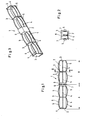
- the straight connector shown in plan view in FIG. 1 consists of the two parts A and B of equal length, part A of which can be inserted into a spacer profile, not shown, and part B into another spacer profile to be connected to the first spacer profile.
- the two parts A and B form the elongated body 1 of the straight connector, which has a flat base plate 2, on which vertical, spaced-apart transverse ribs 3 are arranged, the width of which corresponds to the width of the base plate 2 and the height of which approximately corresponds to the clear height of the Cavity cross section corresponds to the distance profiles.
- the transverse ribs are connected to central webs 4 which are perpendicular to the base plate 2 and which, like the transverse ribs, form a common whole, the height of which can be smaller than that of the transverse ribs.
- two transverse ribs 3 are used for each part A and B of the body 1, one of which is located at the end of the body and the other in the middle of the part in question.
- the body 1 is on its two sides, which come into contact with the profile inner walls when the straight connector is pushed in, the outer surfaces of which accommodate the spaced apart two glass panes of the multi-pane insulating glass, are provided with spring bodies 5 which form arched material strips which curve outwards Extend the longitudinal direction of the body 1 and are inseparably connected at their ends to the side edges of the transverse ribs 3.
- the two parts A and B of the body 1 have j e two on both sides the following spring body 5, the height of which, as can be seen from FIG.
- the two parts A and B of body 1 of equal length are connected by a common center body 6, which in the embodiment shown in FIGS. 1 and 2 is surrounded by a rib running around its circumference, which acts as a stop 7 of the straight connector for the opposite end faces the spacing profile is used, in which the straight connector is inserted.
- a stop is superfluous in cases in which one part of the body is pushed into the associated spacing profile until the end of this body part abuts against an inner wall of the spacing profile, as can be the case, for example, if it is is a curved spacer profile with a short and a long leg, and the straight connector is inserted into the short leg.
- Such an embodiment of the straight connector is shown in FIG. 3 in an isometric view.
- Middle body 6 is particularly necessary when a part of the straight connector is to remain free between the spacing profiles to be connected in the area of the connection point, in order to lead through this part a bore 8 leading into the space between the panes, which is used for venting or gassing the space between the panes serves in a known manner and can then be closed.
- the course of such a bore is indicated by dashed lines in FIG. 2.
- the middle part 6 itself as a stop body for the end faces of the spacer profiles to be connected to one another, by giving this middle part a cross-sectional dimension which still projects beyond the height of the spring body 5.
- the insertion of the straight connector into the opening of the profile cavity can be facilitated in that the straight connector tapers somewhat at its ends.
Landscapes
- Engineering & Computer Science (AREA)
- Civil Engineering (AREA)
- Structural Engineering (AREA)
- Securing Of Glass Panes Or The Like (AREA)
Abstract
Description
- Die Erfindung betrifft einen Geradverbinder, insbesondere aus Kunststoff, für hohle Abstandsprofile eines Mehrscheibenisolierglases.
- Es ist bekannt, hohle Abstandsprofile von Mehrscheibenisoliergläsern durch Eckverbinder an ihren Enden miteinander zu verbinden, um Rahmenprofilkörper herzustellen, auf deren Seitenflächen die mit Abstand getrennten Glasscheiben des Isolierglases befestigt werden. Die Verbindung solcher Abstandsprofile an den vier Ecken derartiger Profilrahmen mittels spezieller Eckverbindungskörper kann jedoch nicht voll befriedigen, weil die Abdichtung der rechtwinklig aufeinanderstossenden Abstandsprofile, durch die das Eindringen von Feuchtigkeit in den Scheibenzwischenraum verhindert werden soll, nicht immer vollständig gelingt und weil darüberhinaus die Stabilität des mit Hilfe solcher Eckverbinderungskörper aus geraden Abstandsprofilen zusammengesetzten Rahmens oftmals zu wünschen übrig lässt.
- Es ist daher vorgeschlagen worden, anstelle von geraden Abstandsprofilen rundgebogene zu verwenden und auf diese Weise das Abdichtungsproblem an den Rahmenecken zu beseitigen und die Verbindungsstelle zweier aufeinanderfolgender, stossender Abstandsprofile in die geraden Seiten des Rahmens zu verlegen.
Die Aufgabe der Erfindung besteht nun darin, für in gerader Linie aufeinanderfolgende Abstandsprofile, die miteinander zu einem Rahmen für Mehrscheibenisolierglas verbunden werden sollen, einen geeigneten Verbindungskörper, Geradverbinder genannt, zu schaffen, der gewährleistet, dass die Abstandsprofile fest, dicht und dauerhaft miteinander verbunden werden, ohne dass der Herstellungsaufwand für einen solchen Geradverbinder im einzelnen und den Profilkörperrahmen in seiner Gesamtheit unangemessen gross wird. - Diese Aufgabe wird erfindungsgemäss gelöst durch einen flachen, länglichen Körper, dessen Querschnitt an den Hohlraumquerschnitt zweier miteinander geradlinig zu verbindender Abstandsprofile angepasst ist und der aus zwei Teilen besteht, von denen der eine Teil in das eine Abstandsprofil und der andere Teil in das andere Abstandsprofil einsteckbar ist und dessen Oberflächen mit Federkörpern versehen sind, welche mit den Innenwänden der Abstandsprofile in Reibungsberührung bringbar sind.
- Ein solcher Geradverbinder, der aufgrund seiner flachen Bauweise auch Flachverbinder genannt werden kann, hat im Bereich seiner Federkörper in bezug auf den Hohlraumquerschnitt der miteinander zu verbindenden Abstandsprofile ein Obermass, so dass die Federkörper beim Hineinpressen des Geradverbinders in den Hohlraum des betreffenden Abstandsprofiles elastisch verformt werden und nach erfolgtem Einschub des Geradverbinders mit den ihnen gegenüberliegenden Innenwänden des Abstandsprofils eine feste Reibschlussverbindung bilden, die ein Herausrutschen des Geradverbinders aus dem Abstandsprofile verhindert. In diesem Zusammenhang hat sich im Hinblick auf die zwischen dem Geradverbinder und den Abstandsprofilwänden herrschenden Druckkräfte bewährt, die Federkörper am Geradverbinder nur auf denjenigen Oberflächen anzuordnen, die den Innenwänden des Abstansprofils gegenüberliegen, welche auf ihren Aussenseiten die beiden Glasscheiben des Mehrscheibenisolierglases aufnehmen. Solche Federkörper können bogenförmig nach aussen gewölbte Materialstreifen sein, die sich in Längsrichtung des Körpers des Geradverbinders erstrecken und an ihren Enden mit den Seiten des Körpers untrennbar verbunden sind. Falls der Körper aus Kunststoff besteht und dann in einem Spritzgussverfahren hergestellt wird, sind die Federkörper Bestandteil des Spritzgusskörpers und mit der Körperoberfläche so fest verbunden, dass sie unter den beim Einschieben des Geradverbinders in den Hohlraum des Abstandsprofils entstehenden Verformungskräften nicht abreissen oder brechen.
- Für den Aufbau des Geradverbinder hat es sich bewährt, dem flachen Körper eine Bodenplatte zu geben, auf der senkrecht stehende, mit Abstand getrennte Querrippen angeordnet sind, deren Breite der Breite der Bodenplatte entspricht und deren Höhe etwa der lichten Höhe des Hohlraumquerschnitts des Abstandsprofiles entspricht. Diese Querrippen können gemäß einer vorteilhaften Ausgestaltung des Erfindungsvorschlags durch auf der Bodenplatte stehende, sich rechtwinklig zu ihnen erstreckende ! Mittelstege miteinander verbunden werden, deren Höhe an sich beliebig ist, jedoch gewöhnlich kleiner ist als die der Querrippen. Die Federkörper können dann an den seitlichen Aussenkanten der Querrippen angebracht werden, so dass der zwischen den aufeinanderfolgenden Querrippen vorhandene, von den Federkörpern überbrückte Raum für die Verformung der Federn zur Verfügung steht, die Federn also zwischen den Querrippen nicht zusätzlich abgestützt sind.
- Die Anzahl der Federkörper, die der Geradverbinder an beiden gegenüberliegenden Körperseiten aufweist, kann gleich gross sein, um eine gleichmässige Druckkraftübertragung zwischen dem Körper und den Innenwänden der Abstandsprofile sicherzustellen. Für das elastische Verhalten der Federkörper hat sich als günstig erwiesen, ihre in Höhe des Hohlraumquerschnitts gemessene Breite wesentlich kleiner zu machen als die Höhe der Querrippen. Ferner ist die Möglichkeit gegeben, in Höhe des Hohlraumquerschnitts gemessen, auch mehrere Federkörper mit Abstand übereinander anzuordnen, um dadurch das Federungsvermögen bzw. die Reibschlussverbindung zwischen dem Körper des Geradverbinders und den Profilinnenwänden in der gewünschten Weise zu beeinflussen.
- Damit das Einschieben der Geradverbinders in den Profilhohlraum nur etwa bis zur halben Länge des Körpers geschieht, also nur der eine Teil in jeweils nur das eine Abstandsprofil eingeschoben wird, während dann der andere Teil des Körpers für das andere Abstandsprofil zur Verfügung steht, hat es sich bewährt, auf dem Körper einen Anschlag anzubringen, der sich in der Mitte der Körperlänge befindet und als eine sich rund um seinen Umfang erstreckende Rippe ausgebildet sein kann, die mit den sich gegenüberliegenden Stirnseiten des Abstandsprofils in Berührung bringbar ist. Die beiden Teile des Körpers lassen sich symmetrisch und gleichlang ausbilden und können durch einen Mittelkörper verbunden sein, der selbst als Anschlag für die Stirnseiten der beiden durch den Geradverbinder zu verbindenden Abstandsprofile dienen kann, so dass dann eine besondere Anschlagrippe nicht vorgesehen zu werden braucht. Dieser Mittelkörper kann vorteilhafterweise mit einer Durchgangsbohrung versehen werden, die verschliessbar ist und zur Entlüftung und/oder Begasung des Isolierscheibenzwischenraums dient.
- Die Erfindung wird nachfolgend anhand des in der Zeichnung dargestellten Ausführungsbeispiels näher erläutert. In der Zeichnung zeigen:
- Fig. 1 eine Draufsicht des Geradverbinders,
- Fig. 2 eine Querschnittansicht längs der Linie II-II in Fig. 1, und
- Fig. 3 eine isometrische Darstellung des Geradverbinders.
- Der in Fig. 1 in Draufsicht dargestellte Geradverbinder besteht aus den beiden gleich langen Teilen A und B, von denen der Teil A in ein nicht gezeigtes Abstandsprofil und der andere Teil B in ein anderes mit dem ersten Abstandsprofil zu verbindendes Abstandsprofil einsteckbar sind. Die beiden Teile A und B bilden den länglichen Körper 1 des Geradverbinders, der eineflache Bodenplatte 2 besitzt, auf der senkrecht stehende, mit Abstand getrennte Querrippen 3 angeordnet sind, deren Breite der Breite der Bodenplatte 2 entspricht und deren Höhe in etwa der lichten Höhe des Hohlraumquerschnitts der Abstandsprofile entspricht. Die Querrippen sind, wie aus Fig. 2 ersichtlich, mit auf der Bodenplatte 2 senkrecht stehenden und mit dieser wie die Querrippen ein gemeinsames Ganzes bildenden Mittelstegen 4 verbunden, deren Höhe kleiner sein kann als diejenige der Querrippen.
- Bei dem in Fig. 1 und 2 gezeigten Ausführungsbeispiel werden für jeden Teil A und B des Körpers 1 zwei Querrippen 3 verwendet, von denen sich die eine jeweils am Körperende befindet und die andere in der Mitte des betreffenden Teils. Der Körper 1 ist an seinen beiden Seiten, die im eingeschobenen Zustand des Geradverbinders mit den Profilinnenwänden in Berührung treten, deren Aussenflächen die mit Abstand getrennten beiden Glasscheiben des Mehrscheibenisolierglases aufnehmen, mit Federkörpem 5 versehen, die bogenförmig nach aussen gewölbte Materialstreifen bilden, welche sich in Längsrichtung des Körpers 1 erstrecken und an ihren Enden mit den Seitenkanten der Querrippen 3 untrennbar verbunden sind. Die beiden Teile A und B des Körpers 1 weisen zu beiden Seiten je zwei aufeinanderfolgende Federkörper 5 auf, deren Höhe, wie aus Fig. 2 ersichtlich, wesentlich kleiner ist als die Höhe der Querrippen 3. Diese Federkörper werden beim Hineinschieben des Geradverbinders in den Hohlraum des betreffenden Abstandsprofils elastisch nach innen in den Raum 9 hineingedrückt und dadurch elastisch verformt, wodurch sie mit den Innenwänden des Hohlprofils eine Reibschlussverbindung herstellen, die bewirkt, dass der Geradverbinder im eingebauten Zustand festsitzt. Die Federungswirkung der Federkörper hängt zweifellos nicht nur von der Stärke der Materialstreifen sowie von der Oberbrückungslänge von Querrippe zu Querrippe ab, sondern auch von der Art des Materials, beispielsweise Kunststoff, aus dem der Geradverbinder beispielsweise im Spritzgussverfahren hergestellt wird.
- Die beiden gleichlangen Teile A und B des Körpers 1 sind durch einen gemeinsamen Mittelkörper 6 verbunden, der bei der in Fig. 1 und 2 gezeigten Ausführungsform von einer rund um seinen Umfang laufenden Rippe umgeben ist, welche als Anschlag 7 des Geradverbinders für die gegenüberliegenden Stirnseiten der Abstandsprofile dient, in die der Geradverbinder eingesteckt wird. Ein solcher Anschlag erübrigt sich in den Fällen, in denen das Hineinschieben des einen Teils des Körpers in das zugehörige Abstandsprofil so weit erfolgt, bis das Ende dieses Körperteils gegen eine Innenwand des Abstandsprofils stösst, wie dies beispielsweise dann der Fall sein kann, wenn es sich um ein rundgebogenes Abstandsprofil mit einem kurzen und einem langen Schenkel handelt, und der Geradverbinder in den kurzen Schenkel eingesteckt wird. Eine solche Ausführungsform des Geradverbinders ist in Fig. 3 in isometrischer Ansicht dargestellt.
- Wenn im letzteren Fall ein besonderer Anschlag 7, beispielsweise in Form einer umlaufenden Rippe in der Mitte des Körpers 1, nicht erforderlich ist, kommen die Stirnseiten der beiden durch den Geradverbinder zu verbindenden Abstandsprofile beim Zusammenbau der Profile und ihrer Verbindung in direkte Berührung, wodurch die Stabilität der Verbindungsstelle möglicherweise noch vergrössert wird.
- Der beiden dargestellten Ausführungsformen eigene ; Mittelkörper 6 ist vor allem dann erdorderlich, wenn zwischen den miteinander zu verbindenden Abstandsprofilen im Bereich der Verbindungsstelle ein Teil des Geradverbinders frei bleiben soll, um durch diesen Teil eine in den Scheibenzwischenraum führende Bohrung 8 hindurchzuführen, die zur Entlüftung bzw. Begasung des Scheibenzwischenraumes in an sich bekannter Weise dient und danach verschliessbar ist. Der Verlauf einer solchen Bohrung ist in Fig. 2 gestrichelt angedeutet.
- Des weiteren ist die nicht dargestellte Möglichkeit gegeben, den Mittelteil 6 selbst als Anschlagkörper für die Stirnseiten der miteinander zu verbindenden Abstandsprofile auszubilden, indem dieser Mittelteil eine Querschnittsabmessung erhält, die noch über die Höhe der Federkörper 5 hinausragt. Ausserdem kann das Hineinstecken des Geradverbinders in die öffnugn des Profilhohlraums dadurch erleichtert werden, dass sich der Geradverbinder an seinen Enden etwas verjüngt.
Claims (10)
Applications Claiming Priority (2)
| Application Number | Priority Date | Filing Date | Title |
|---|---|---|---|
| DE2809822 | 1978-03-07 | ||
| DE19782809822 DE2809822A1 (de) | 1978-03-07 | 1978-03-07 | Geradverbinder fuer hohle abstandsprofile eines mehrscheibenisolierglases |
Publications (3)
| Publication Number | Publication Date |
|---|---|
| EP0004006A2 true EP0004006A2 (de) | 1979-09-19 |
| EP0004006A3 EP0004006A3 (en) | 1979-10-31 |
| EP0004006B1 EP0004006B1 (de) | 1981-09-02 |
Family
ID=6033795
Family Applications (1)
| Application Number | Title | Priority Date | Filing Date |
|---|---|---|---|
| EP19790100551 Expired EP0004006B1 (de) | 1978-03-07 | 1979-02-23 | Geradverbinder, insbesondere aus Kunststoff, für hohle Abstandsprofile eines Mehrscheibenisolierglases |
Country Status (4)
| Country | Link |
|---|---|
| EP (1) | EP0004006B1 (de) |
| AT (1) | AT377969B (de) |
| DE (1) | DE2809822A1 (de) |
| DK (1) | DK92879A (de) |
Cited By (7)
| Publication number | Priority date | Publication date | Assignee | Title |
|---|---|---|---|---|
| FR2434919A1 (fr) * | 1978-08-30 | 1980-03-28 | Bfg Glassgroup | Cadre d'ecartement constitue principalement d'un profile metallique creux pour des ensembles isolants de verre |
| DE3408600A1 (de) * | 1984-03-09 | 1985-09-12 | Hans Joachim 5650 Solingen Kronenberg | Verbinder fuer hohlprofile |
| AU573068B2 (en) * | 1985-05-16 | 1988-05-26 | Ppg Industries, Inc. | Breather insulated window unit |
| EP0535305A1 (de) * | 1991-09-04 | 1993-04-07 | CERA Handelsgesellschaft mbH | Geradverbinder aus Kunststoff zur Verbindung von hohlen Abstandsprofilen und hohlen Sprossenprofilen eines Mehrscheibenisolierglases |
| EP0675259A1 (de) * | 1994-03-30 | 1995-10-04 | CERA Handelsgesellschaft mbH | Doppeläufiger Geradverbinder für aus zwei Profilsträngen gebildete Abstandsprofile eines Mehrscheibenisolierglases |
| EP0750090A3 (de) * | 1995-06-21 | 1997-11-19 | CERA Handelsgesellschaft mbH | Linearverbinder aus Kunststoff zur Verbindung von hohlen Abstandhalterprofilen von Mehrscheibenisoliergläsern |
| EP1050658A3 (de) * | 1999-05-04 | 2003-06-04 | CERA Handelsgesellschaft mbH | Linearverbinder aus Kunststoff für Abstandhalterprofile von Mehrscheibenisoliergläsern |
Families Citing this family (4)
| Publication number | Priority date | Publication date | Assignee | Title |
|---|---|---|---|---|
| DE3236110C2 (de) * | 1982-09-29 | 1985-10-10 | Eduard Kronenberg GmbH & Co, 5650 Solingen | Steckverbinder für die geradlinige Stoßverbindung von Hohlprofilen |
| DE3327366A1 (de) * | 1983-07-29 | 1985-02-14 | Franz Xaver Bayer Isolierglasfabrik KG, 7807 Elzach | Verbindungsstueck fuer hohlprofile, die als abstandhalter fuer isolierglasscheiben od. dgl. dienen |
| DE3806845A1 (de) * | 1988-03-03 | 1989-09-14 | Bayer Isolierglasfab Kg | Geradverbindungsstueck zum eingreifen in als distanzhalter fuer isolierglasscheiben dienende hohlprofile |
| DE3822839A1 (de) * | 1988-07-06 | 1990-01-11 | Arup Alu Rohr Und Profil Gmbh | Verbindungselement fuer stege von mehrscheiben-isolierglas |
Family Cites Families (5)
| Publication number | Priority date | Publication date | Assignee | Title |
|---|---|---|---|---|
| DE2314776A1 (de) * | 1973-03-24 | 1974-09-26 | Erbsloeh Julius & August | Anordnung zur herstellung von isolierverglasungen |
| DE2537017C3 (de) * | 1975-08-20 | 1978-08-17 | Bfg Glassgroup, Paris | Abstandshalterrahmen für Isolierglaseinheiten |
| DE2647705C3 (de) * | 1976-10-21 | 1981-05-21 | Cera Handelsgesellschaft Mbh, 8954 Biessenhofen | Eckverbindungswinkel für hohle Abstandsprofile eines Mehrscheibenisolierglases |
| DE2746607B1 (de) * | 1977-10-15 | 1979-05-03 | Erbsloeh Julius & August | Abstandhalter fuer Mehrscheiben-Isolierglas,bestehend aus einem zu einem Rahmen geformten Hohlprofil |
| DE7825704U1 (de) * | 1978-08-30 | 1978-12-21 | Bfg Glassgroup, Paris | Im wesentlichen aus einem Metallhohlprofil bestehende Abstandshalterrahmen für Isolierglaseinheiten |
-
1978
- 1978-03-07 DE DE19782809822 patent/DE2809822A1/de not_active Withdrawn
-
1979
- 1979-02-21 AT AT132479A patent/AT377969B/de not_active IP Right Cessation
- 1979-02-23 EP EP19790100551 patent/EP0004006B1/de not_active Expired
- 1979-03-06 DK DK92879A patent/DK92879A/da not_active Application Discontinuation
Cited By (7)
| Publication number | Priority date | Publication date | Assignee | Title |
|---|---|---|---|---|
| FR2434919A1 (fr) * | 1978-08-30 | 1980-03-28 | Bfg Glassgroup | Cadre d'ecartement constitue principalement d'un profile metallique creux pour des ensembles isolants de verre |
| DE3408600A1 (de) * | 1984-03-09 | 1985-09-12 | Hans Joachim 5650 Solingen Kronenberg | Verbinder fuer hohlprofile |
| AU573068B2 (en) * | 1985-05-16 | 1988-05-26 | Ppg Industries, Inc. | Breather insulated window unit |
| EP0535305A1 (de) * | 1991-09-04 | 1993-04-07 | CERA Handelsgesellschaft mbH | Geradverbinder aus Kunststoff zur Verbindung von hohlen Abstandsprofilen und hohlen Sprossenprofilen eines Mehrscheibenisolierglases |
| EP0675259A1 (de) * | 1994-03-30 | 1995-10-04 | CERA Handelsgesellschaft mbH | Doppeläufiger Geradverbinder für aus zwei Profilsträngen gebildete Abstandsprofile eines Mehrscheibenisolierglases |
| EP0750090A3 (de) * | 1995-06-21 | 1997-11-19 | CERA Handelsgesellschaft mbH | Linearverbinder aus Kunststoff zur Verbindung von hohlen Abstandhalterprofilen von Mehrscheibenisoliergläsern |
| EP1050658A3 (de) * | 1999-05-04 | 2003-06-04 | CERA Handelsgesellschaft mbH | Linearverbinder aus Kunststoff für Abstandhalterprofile von Mehrscheibenisoliergläsern |
Also Published As
| Publication number | Publication date |
|---|---|
| DE2809822A1 (de) | 1979-09-13 |
| EP0004006A3 (en) | 1979-10-31 |
| ATA132479A (de) | 1984-10-15 |
| EP0004006B1 (de) | 1981-09-02 |
| DK92879A (da) | 1979-09-08 |
| AT377969B (de) | 1985-05-28 |
Similar Documents
| Publication | Publication Date | Title |
|---|---|---|
| EP0133655B1 (de) | Verbindungsstück für Hohlprofile, die als Abstandhalter für Isolierglasscheiben oder dgl. dienen | |
| DE2502989B2 (de) | Bauelement | |
| EP1227210A2 (de) | Steckverbinder aus Kunststoff zur Verbindung von hohlen Abstandsprofilen und hohlen Sprossenprofilen eines Mehrscheibenisolierglases | |
| EP0004006B1 (de) | Geradverbinder, insbesondere aus Kunststoff, für hohle Abstandsprofile eines Mehrscheibenisolierglases | |
| DE3310370C2 (de) | Winkelig, vorzugsweise rechtwinkelig, miteinander verbundene Wandungen o.dgl. übereinstimmender Breite | |
| EP0330906B1 (de) | Geradverbindungsstück zum Eingreifen in als Distanzhalter für Isolierglasscheiben dienende Hohlprofile | |
| DE2911832C2 (de) | Wärmedämmendes Verbundprofil | |
| EP0339319B1 (de) | Geradverbinder für hohle Abstandsprofile eines Mehrscheibenisolierglases | |
| DE4302662A1 (de) | Halteelement zum vertikalen Fixieren einer in einem Fensterrahmen eines Kraftfahrzeuges einklebbaren Glasscheibe | |
| DE3401106C2 (de) | ||
| DE2015414C3 (de) | Vorrichtung zum Verbinden zweier an ihren Enden auf Gehrung geschnittener Metallprofile zu einer Rahmenecke | |
| DE10346305B4 (de) | Winkelverbinder für Doppelfenster-Rahmenhohlprofile | |
| DE102011055539A1 (de) | Steckverbinder | |
| EP0535305B1 (de) | Geradverbinder aus Kunststoff zur Verbindung von hohlen Abstandsprofilen und hohlen Sprossenprofilen eines Mehrscheibenisolierglases | |
| DE2203237A1 (de) | Zusammengesetztes waermeisolierendes profil fuer fensterrahmen, tuerrahmen oder dgl | |
| DE2364908C3 (de) | Eckverbindung für Abstandsprofile für Mehrscheibenisolierglas | |
| DE2541294C3 (de) | Türblatt, Torblatt, Trennwand o.dgl | |
| DE7806876U1 (de) | Geradverbinder fuer hohle abstandsprofile eines mehrscheibenisolierglases | |
| DE3439787A1 (de) | Klappladen | |
| EP0004007B1 (de) | Verfahren zur Verbindung von rundgebogenen und geraden, hohlen Abstandsprofilen für Mehrscheibenisoliergläser | |
| EP0687790A1 (de) | Linearverbinder für hohle Abstandsprofile eines Mehrscheibenisolierglases | |
| DE8617167U1 (de) | Geradverbinder, insbesondere aus Kunststoff, zur Verbindung von hohlen Abstandsprofilen und hohlen Sprossenprofilen eines Mehrscheibenisolierglases | |
| DE9217883U1 (de) | Klotzteil zum Festsetzen von Glasscheiben o.dgl. in Nuten von Tür- oder Fensterrahmen | |
| DE2416615C3 (de) | Eckverbindung für Abstandsprofile für Mehrscheibenisolierglas | |
| DE9201532U1 (de) | Geradverbinder für hohle Abstandsprofile von Mehrscheibenisoliergläsern |
Legal Events
| Date | Code | Title | Description |
|---|---|---|---|
| PUAI | Public reference made under article 153(3) epc to a published international application that has entered the european phase |
Free format text: ORIGINAL CODE: 0009012 |
|
| PUAL | Search report despatched |
Free format text: ORIGINAL CODE: 0009013 |
|
| AK | Designated contracting states |
Designated state(s): BE CH FR GB IT LU NL SE |
|
| AK | Designated contracting states |
Designated state(s): BE CH FR GB IT LU NL SE |
|
| 17P | Request for examination filed | ||
| ITF | It: translation for a ep patent filed | ||
| GRAA | (expected) grant |
Free format text: ORIGINAL CODE: 0009210 |
|
| AK | Designated contracting states |
Designated state(s): BE CH FR GB IT LU NL SE |
|
| PLBI | Opposition filed |
Free format text: ORIGINAL CODE: 0009260 |
|
| PG25 | Lapsed in a contracting state [announced via postgrant information from national office to epo] |
Ref country code: LU Free format text: LAPSE BECAUSE OF NON-PAYMENT OF DUE FEES Effective date: 19820228 |
|
| 26 | Opposition filed |
Opponent name: WILH. FRANK GMBH Effective date: 19810902 |
|
| PLAB | Opposition data, opponent's data or that of the opponent's representative modified |
Free format text: ORIGINAL CODE: 0009299OPPO |
|
| R26 | Opposition filed (corrected) |
Opponent name: WILH. FRANK GMBH Effective date: 19820123 |
|
| PGFP | Annual fee paid to national office [announced via postgrant information from national office to epo] |
Ref country code: CH Payment date: 19840220 Year of fee payment: 6 |
|
| PGFP | Annual fee paid to national office [announced via postgrant information from national office to epo] |
Ref country code: LU Payment date: 19840222 Year of fee payment: 6 |
|
| PGFP | Annual fee paid to national office [announced via postgrant information from national office to epo] |
Ref country code: NL Payment date: 19840229 Year of fee payment: 6 |
|
| PGFP | Annual fee paid to national office [announced via postgrant information from national office to epo] |
Ref country code: FR Payment date: 19840301 Year of fee payment: 6 |
|
| PGFP | Annual fee paid to national office [announced via postgrant information from national office to epo] |
Ref country code: SE Payment date: 19840331 Year of fee payment: 6 Ref country code: BE Payment date: 19840331 Year of fee payment: 6 |
|
| RDAG | Patent revoked |
Free format text: ORIGINAL CODE: 0009271 |
|
| STAA | Information on the status of an ep patent application or granted ep patent |
Free format text: STATUS: PATENT REVOKED |
|
| 27W | Patent revoked |
Effective date: 19840528 |
|
| REG | Reference to a national code |
Ref country code: CH Ref legal event code: PL |
|
| GBPR | Gb: patent revoked under art. 102 of the ep convention designating the uk as contracting state | ||
| BERE | Be: lapsed |
Owner name: CERA HANDELS-G.M.B.H. Effective date: 19850223 |
|
| REG | Reference to a national code |
Ref country code: FR Ref legal event code: ST |
|
| EUG | Se: european patent has lapsed |
Ref document number: 79100551.5 Effective date: 19860129 |