EP0004985A1 - Zug zum Erneuern eines Eisenbahngleises - Google Patents
Zug zum Erneuern eines Eisenbahngleises Download PDFInfo
- Publication number
- EP0004985A1 EP0004985A1 EP79200154A EP79200154A EP0004985A1 EP 0004985 A1 EP0004985 A1 EP 0004985A1 EP 79200154 A EP79200154 A EP 79200154A EP 79200154 A EP79200154 A EP 79200154A EP 0004985 A1 EP0004985 A1 EP 0004985A1
- Authority
- EP
- European Patent Office
- Prior art keywords
- wagon
- ballast
- train
- wagons
- track
- Prior art date
- Legal status (The legal status is an assumption and is not a legal conclusion. Google has not performed a legal analysis and makes no representation as to the accuracy of the status listed.)
- Granted
Links
- 239000000969 carrier Substances 0.000 claims abstract description 6
- 238000003860 storage Methods 0.000 claims description 8
- 241001669679 Eleotris Species 0.000 claims description 4
- 230000008021 deposition Effects 0.000 claims description 3
- 230000000284 resting effect Effects 0.000 claims description 3
- 239000000843 powder Substances 0.000 claims 1
- 238000012216 screening Methods 0.000 abstract description 9
- 238000009412 basement excavation Methods 0.000 abstract description 7
- 239000000463 material Substances 0.000 abstract description 5
- 238000009434 installation Methods 0.000 description 3
- 238000005259 measurement Methods 0.000 description 3
- 238000005096 rolling process Methods 0.000 description 3
- 239000000523 sample Substances 0.000 description 3
- 238000000034 method Methods 0.000 description 2
- 241000153282 Theope Species 0.000 description 1
- 238000007792 addition Methods 0.000 description 1
- 230000000694 effects Effects 0.000 description 1
- 230000002706 hydrostatic effect Effects 0.000 description 1
- 238000012432 intermediate storage Methods 0.000 description 1
- 230000035699 permeability Effects 0.000 description 1
- 230000001105 regulatory effect Effects 0.000 description 1
Images



Classifications
-
- E—FIXED CONSTRUCTIONS
- E01—CONSTRUCTION OF ROADS, RAILWAYS, OR BRIDGES
- E01B—PERMANENT WAY; PERMANENT-WAY TOOLS; MACHINES FOR MAKING RAILWAYS OF ALL KINDS
- E01B29/00—Laying, rebuilding, or taking-up tracks; Tools or machines therefor
- E01B29/05—Transporting, laying, removing, or renewing both rails and sleepers
-
- E—FIXED CONSTRUCTIONS
- E01—CONSTRUCTION OF ROADS, RAILWAYS, OR BRIDGES
- E01B—PERMANENT WAY; PERMANENT-WAY TOOLS; MACHINES FOR MAKING RAILWAYS OF ALL KINDS
- E01B27/00—Placing, renewing, working, cleaning, or taking-up the ballast, with or without concurrent work on the track; Devices therefor; Packing sleepers
- E01B27/06—Renewing or cleaning the ballast in situ, with or without concurrent work on the track
- E01B27/11—Renewing or cleaning the ballast in situ, with or without concurrent work on the track combined with concurrent renewal of track components
Definitions
- the present invention relates to a train for renewing a railway track, comprising, in addition to the wagons for transporting the rails, sleepers and fasteners, at least one train of working wagons comprising a deposition wagon, a stripping, a laying wagon, a wagon of worming and means of transport of the spent ballast towards a screener installed on a wagon placed outside the renewal zone as well as means of transport bringing the screened ballast towards a storage silo and distribution for its distribution on the new track, as well as the means of transport for old sleepers or spans and new sleepers.
- the renewal of a railway track includes, in addition to the replacement of the rails and sleepers, the renewal of the ballast, because an old ballast, soiled with detritus and clogged, no longer has the required elasticity and permeability properties.
- the successive additions of gravel during the operations of rectification and stuffing of the sleepers have the effect of raising the track, which has serious drawbacks mainly when passing engineering structures.
- stripping-screening of the ballast is normally done before or after laying the new track. The duration of this operation is therefore added to that of other renewal operations.
- the stripping-screening requires the lifting of the whole track by means of powerful machines, at the risk of deforming the new rails. Since the machines for stripping and screening the ballast are very large machines, their implementation is accompanied by long and complicated operations, both as regards their starting up and as regards their stopping.
- patent CH.583 822 which relates to a process for the complete renewal of a railway track, in which the procedure for removing the old track, stripping and screening the ballast and laying the new one track operates in a single pass of the complete renewal train, provided for this purpose.
- the same patent also includes a train for the complete renewal of a railway track, comprising, in addition to the wagons for transporting the rails, sleepers and fasteners, at least one installation and removal train fitted with gantries, and frame wagons, as known from patents Nos. 549 692 and 585 814 of the same owners.
- said renewal train are incorporated bodies for stripping and transporting the ballast to a screener installed on a wagon placed outside the renewal area.
- the present invention as characterized by the claims, provides an improved renewal train such that all the operations of removing the old sleepers and old rails, the excavation of the worn ballast, as well as the laying of the new sleepers and new rails are made without stopping the machine, when removing the old sleepers and rails, and so that the train fits even better in the gauge of passage, while increasing the width of the wagons work, and reducing their wheelbase.
- the deposit wagon comprises a lifting system making it possible to lift and turn at least one cross member or one span around at least one of the transport elements.
- of ballast by the fact that the working wagons are interconnected by connecting frames resting on chassis equipped to move on the ballast and / or on the bare bench, or on the screened ballast and which can be lowered more or less in relation to the respective connecting frames, so as to raise the bogies of the working wagons in the working area, and by the fact that each connecting frame connects two wagons by means of articulations and guide parts which are used to maintain the position of the working car concerned in relation to the connecting frame.
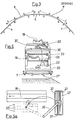
- the renewal train consists of six main elements, shown diagrammatically in FIGS. 1 and 2, namely a screener, not shown, a deposit wagon 5, a stripping machine 6, a laying wagon 7, a wagon and a gantry with transport beam, not shown.
- the screening machine and the wagon are normal wagons with two bogies.
- the deposit wagon 5, the stripper 6 and the laying wagon 7 constitute an articulated train fitted with six bogies 12 to 17 and two tracked chassis 11 and 11 '.
- the screening machine and the first bogie 12 of the deposit wagon 5 roll on the old track 1.
- the central part of the train rests on the two track chassis 11 and 11 'which roll respectively on the ballast and on the excavated bench, or on the screened ballast.
- the rear bogie 17 of the laying wagon 7 as well as the dowelling wagon roll on the new track 4.
- the two crawler chassis and the crosspiece laying device are either guided by probes using the parallel track as reference, or driven using a measurement and control system placed on the screener, the deposit wagon, the stripper and the laying wagon, as shown in Figure 3.
- the geometric points A, B, C, D, E, F and b, c, d, e, are shown in Figure 1.
- the working wagons (5,6,7) are linked together by connecting frames (8,8 ') resting on tracked chassis (11,11').
- Each connecting frame (8.8 ') connects two wagons by means of cardan joints (9).
- Guide pieces (10) are used to maintain the chassis of the wagon concerned in its transverse position relative to the connection frame (8) and, hydraulic stops (42) guide the connection frame concerned in a longitudinal position determined relative to the wagon chassis.
- the automatic controls are designed in such a way that the two tracked chassis follow the layout of the old track or a parallel layout if the distances between the tracks are to be changed.
- the deposit wagon 5, FIGS. 1 and 4 is supported at the front on a bogie 12 and at the rear, by means of an articulated frame 8 on the tracked chassis 11.
- the transporters 18 for the excavated material In the wagon are mounted , the transporters 18 for the excavated material and, above, the transporters 19 for the recovered ballast.
- the removal and transport of the old sleepers is carried out using a hydraulic picker 20, chain transporters 21 , and an elevator 22.
- roller clamps not shown, lift and move aside the old rails 1 which are then routed along the machine to be deposited at the rear on the bench or in the axis of the track.
- the hydraulic picker 20 takes out the old sleepers 32 one after the other from the ballast and places them on a chain conveyor 21 which brings them on a storage conveyor 21 '.
- the elevator 22 then lifts the turned sleepers 33 next to the worn ballast conveyor 18 above the level of the sleeper transporter 23.
- the sleepers are then pivoted and turned forward still in the track plan, and they are then placed on the conveyor 23 to be conveyed to the transport gantries. After which the elevator returns by the same path to its starting position.
- All movements of the work cycle can be controlled automatically or manually.
- the deposit wagon can be provided with an elevator 22 arranged to lift and pivot in the track plane the sleepers both around the spent ballast 18 and screened ballast conveyors 19.
- the rotary elevator 43 fitted with hydraulic clamps 44 mounted on a lifting system takes three crosspieces on the storage conveyor and raises them against the elevator.
- the elevator turns the sleepers around the spent ballast conveyors 18 and screened ballast conveyors 19 and places them upside down on the upper level, from where they are seized by the mobile conveyor 45 to be conveyed to the gantries. After which the elevator 43 returns to its starting position. All cycle movements are controlled automatically or manually.
- the deposit wagon can be provided with an elevator 43 designed to turn the sleepers only around the spent ballast transporter 18 as in FIG. 5, but the sleepers are placed upside down on the transporter 45.
- the deposition wagon 5 comprises a central beam 24 in which the transporter is housed 18 for the excavated material and above, the transporter 19 for the recovered ballast.
- a rotary elevator 26, equipped with the lifting system and the track 40 of the lorrys 41 is suspended by means of the rollers 27 on the central beam 24.
- the lifting system consists of two pairs of rolling clamps 28 fixed on articulated frames 29, jacks for lifting and lateral movement of the clamps.
- the spans are placed upside down on lorrys 41 which run on a raceway 40.
- the deposit wagon can be provided with an elevator 26 arranged to lift and rotate the spans both around the spent ballast 18 and screened ballast conveyors 19.
- the dismantling of the spans can be carried out without interrupting the work of the machine. While the next span is being taken, the one stored on the stripper is advanced by another train of lorrys to the laying wagon where it is taken by gantry cranes and transported on loading wagons.
- the stripper 6 (fig.l) is equipped with two bogies 14 and 15, an excavator 30, a ballast metering device and transport elements for ballast, sleepers or spans.
- This wagon is connected at the head with the delivery wagon and at the tail to the laying wagon, each time via an articulated connection frame 8 provided with a tracked chassis 11.
- the stripper s' presses on the two tracked chassis 11 and 11 'which run on the old ballast and the bench excavated, or on the screened ballast.
- the excavator 30 consists of an excavation chain and an equalizing blade 25.
- the excavator is articulated to the chassis and suspended by hydraulic cylinders which allow the working depth and the inclination of the machine to be adjusted. the platform.
- the blade is fitted with adjustable side flaps during work using hydraulic cylinders. Behind the leveling blade can be placed groomers to compact the platform.
- the excavated material is brought by the excavation chains on the conveyors 18 to be conveyed to the screener.
- the recovered and screened ballast is then brought back by the transporters 19 to the rear of the train in the metering device of the recovered ballast which consists of a fixed silo and a metering element adjustable in height according to the layers of ballast necessary.
- the ballast is brought to the doser to form the first layer of ballast and the surplus is put on an intermediate conveyor to be evacuated to the ballast distributor on the laying wagon.
- Behind the dispenser a tamper is placed to compact the ballast before the installation of the sleepers.
- the present invention proposes a transport link established at will but, preferably automatically at each stop of the train. For this, is placed between the transport chains of the screened ballast 19 and the spent ballast 18, a funnel 31 placed as close as possible to the excavation chain.
- the transport link which creates a closed circuit between the screened and spent ballast is carried out by moving the screened ballast conveyor 19 'using a hydraulic cylinder 39 when the machine stops.
- the laying wagon 7 provided with two bogies 16 and 17 is equipped with members for laying sleepers with the transport elements, members for laying the rails and the ballast distributor. During work, the wagon leans forward on the 8 'tracked connecting frame and back on the bogie 17 which rolls on the new track 4. In the rear part of the laying wagon are mounted the laying members of new rails with roller clamps.
- the new sleepers stored on transport wagons, are transported by gantry cranes to the storage transporter of the hauling wagon.
- the intermediate transporter spreads the sleepers and brings them to tweezers at the tail of the laying wagon.
- the grippers lift and turn two crosspieces at the same time, place them on the shared longitudinal conveyor several sections for intermediate storage.
- the longitudinal conveyor routes the sleepers to the laying device where they are centered, positioned and then laid on the ballast.
- the installation distance is regulated by a measuring system which allows the distance to be varied from cm to cm.
- the lateral positioning of the sleepers is carried out either by means of a probe which controls the distance between the axis of the sleepers and the parallel track, or by the measurement and control system on the work wagons.
- the train also includes a drawing wagon, not shown, equipped with a storage transporter for the new sleepers, with drawing wrenches for mounting the fasteners of the new rails.
- a drawing wagon not shown, equipped with a storage transporter for the new sleepers, with drawing wrenches for mounting the fasteners of the new rails.
- the wagon is used as a transport wagon for gantry cranes.
- the wagon is dimensioned in such a way that, inside, the staff can mount the rail fasteners.
- the train also includes two self-propelled gantries, according to patent C H. 549 692 which transport the old and new sleepers between the work cars and the transport cars.
- the two gantries are connected to each other by a central beam to which is suspended, by means of cables and hydraulic jacks, a beam for transporting the sleepers. It is fitted with hydraulically operated clamps for gripping crosspieces or spans.
Landscapes
- Engineering & Computer Science (AREA)
- Architecture (AREA)
- Civil Engineering (AREA)
- Structural Engineering (AREA)
- Machines For Laying And Maintaining Railways (AREA)
Priority Applications (1)
| Application Number | Priority Date | Filing Date | Title |
|---|---|---|---|
| DE8080200510T DE2966697D1 (en) | 1978-04-19 | 1979-04-02 | Train for the renewal of a railway track |
Applications Claiming Priority (2)
| Application Number | Priority Date | Filing Date | Title |
|---|---|---|---|
| CH4178/78 | 1978-04-19 | ||
| CH417878A CH620005A5 (de) | 1978-04-19 | 1978-04-19 |
Related Child Applications (1)
| Application Number | Title | Priority Date | Filing Date |
|---|---|---|---|
| EP80200510.8 Division-Into | 1979-04-02 |
Publications (2)
| Publication Number | Publication Date |
|---|---|
| EP0004985A1 true EP0004985A1 (de) | 1979-10-31 |
| EP0004985B1 EP0004985B1 (de) | 1981-09-02 |
Family
ID=4271247
Family Applications (2)
| Application Number | Title | Priority Date | Filing Date |
|---|---|---|---|
| EP80200510A Expired EP0019984B1 (de) | 1978-04-19 | 1979-04-02 | Zug zum Erneuern eines Eisenbahngleises |
| EP79200154A Expired EP0004985B1 (de) | 1978-04-19 | 1979-04-02 | Zug zum Erneuern eines Eisenbahngleises |
Family Applications Before (1)
| Application Number | Title | Priority Date | Filing Date |
|---|---|---|---|
| EP80200510A Expired EP0019984B1 (de) | 1978-04-19 | 1979-04-02 | Zug zum Erneuern eines Eisenbahngleises |
Country Status (6)
| Country | Link |
|---|---|
| US (2) | US4307667A (de) |
| EP (2) | EP0019984B1 (de) |
| AT (1) | AT363113B (de) |
| CA (1) | CA1131502A (de) |
| CH (1) | CH620005A5 (de) |
| ES (1) | ES479737A1 (de) |
Cited By (3)
| Publication number | Priority date | Publication date | Assignee | Title |
|---|---|---|---|---|
| EP0085790A1 (de) * | 1982-02-09 | 1983-08-17 | Les Fils D'auguste Scheuchzer S.A. | Bauzug zur Erneuerung einer Eisenbahnschienenstrecke |
| US5181472A (en) * | 1990-07-13 | 1993-01-26 | Les Fils D'auguste Scheuchzer S.A. | Device for the substitution of the rails of railway tracks |
| EP1396577A1 (de) * | 2002-09-05 | 2004-03-10 | Franz Plasser Bahnbaumaschinen-Industriegesellschaft m.b.H. | Maschine zum Abbau eines Gleises und Verfahren |
Families Citing this family (41)
| Publication number | Priority date | Publication date | Assignee | Title |
|---|---|---|---|---|
| AT370151B (de) * | 1981-03-04 | 1983-03-10 | Plasser Bahnbaumasch Franz | Schotterbett-reinigungsmaschine und hartschaumplatten-verlegung |
| IT1179729B (it) * | 1984-07-10 | 1987-09-16 | Enrico Valditerra | Convoglio per il rinnovamento di strade ferrate |
| US4571825A (en) * | 1984-07-20 | 1986-02-25 | Skibsted Eric T M | Railroad track removing apparatus |
| AT381334B (de) * | 1984-08-13 | 1986-09-25 | Wageneder Sbm Gmbh | Umbauwagen fuer gleisanlagen |
| US6678360B1 (en) | 1985-07-10 | 2004-01-13 | Ronald A. Katz Technology Licensing, L.P. | Telephonic-interface statistical analysis system |
| US20020085692A1 (en) * | 1985-07-10 | 2002-07-04 | Ronald A. Katz Technology Licensing, L.P. | Voice-data telephonic interface control system |
| US4845739A (en) | 1985-07-10 | 1989-07-04 | Fdr Interactive Technologies | Telephonic-interface statistical analysis system |
| GB8517409D0 (en) * | 1985-07-10 | 1985-08-14 | Trailer Train Ltd | Adapter |
| US5828734A (en) | 1985-07-10 | 1998-10-27 | Ronald A. Katz Technology Licensing, Lp | Telephone interface call processing system with call selectivity |
| US5898762A (en) * | 1985-07-10 | 1999-04-27 | Ronald A. Katz Technology Licensing, L.P. | Telephonic-interface statistical analysis system |
| US5359645A (en) | 1985-07-10 | 1994-10-25 | First Data Corporation Inc. | Voice-data telephonic interface control system |
| US5793846A (en) | 1985-07-10 | 1998-08-11 | Ronald A. Katz Technology Licensing, Lp | Telephonic-interface game control system |
| US20020034283A1 (en) * | 1987-02-24 | 2002-03-21 | Ronald A. Katz Technology Licensing, L.P. | Voice-data telephonic interface control system |
| US5012413A (en) * | 1988-07-27 | 1991-04-30 | Pandrol Jackson, Inc. | Railroad track curve lining apparatus and method |
| CH686144A5 (fr) * | 1991-10-30 | 1996-01-15 | Matisa Materiel Ind Sa | Train de renouvellement d'une voie ferree. |
| DE9305927U1 (de) * | 1993-04-20 | 1994-05-26 | Franz Plasser Bahnbaumaschinen-Industriegesellschaft M.B.H., Wien | Maschine zum Erneuern bzw. Verlegen eines Eisenbahngleises |
| FR2757817B1 (fr) * | 1997-01-02 | 1999-02-26 | Gec Alsthom Transport Sa | Dispositif et procede de commande des dispositifs actionneurs pour la suspension active des vehicules, notamment ferroviaires |
| DE10008986A1 (de) * | 2000-02-25 | 2001-08-30 | Gsg Knape Gleissanierung Gmbh | Verfahren zur Erneuerung oder zum Umbau einer Gleisanlage und Vorrichtung hierfür |
| AT3919U3 (de) * | 2000-07-13 | 2001-08-27 | Plasser Bahnbaumasch Franz | Maschine zum abbau eines alten und verlegen eines neuen gleises |
| US6546878B1 (en) | 2001-10-12 | 2003-04-15 | Gunderson, Inc. | Multi-unit railroad freight car for carrying cargo containers |
| US6510800B1 (en) * | 2001-10-12 | 2003-01-28 | Gunderson, Inc. | Multi-unit railroad freight car for carrying cargo containers between container well units |
| US7350467B2 (en) | 2004-08-20 | 2008-04-01 | Loram Maintenance Of Way, Inc. | Long rail pick-up and delivery system |
| US20060277093A1 (en) * | 2005-05-26 | 2006-12-07 | Barnhouse William Iii | System and method of automatic polling |
| US20080053332A1 (en) * | 2006-08-30 | 2008-03-06 | John Roy | Apparatus for enabling an excavator to mount, demount and travel on railroad tracks |
| US20090101042A1 (en) * | 2006-08-30 | 2009-04-23 | Glyde-Rail Licensing, Llc | Apparatus for enabling an excavator to mount, demount and travel on railroad tracks |
| US7607396B2 (en) | 2007-11-14 | 2009-10-27 | Gunderson Llc | Container car side sills |
| DE102008026873B4 (de) * | 2008-06-05 | 2012-02-02 | Ralf Zürcher | Arbeitswagen |
| US7757610B2 (en) | 2008-07-30 | 2010-07-20 | Gunderson Llc | Shortened container well |
| AT507333B1 (de) * | 2008-10-09 | 2011-09-15 | Hans Kuenz Ges M B H | Portalkran |
| US8291592B2 (en) * | 2010-03-17 | 2012-10-23 | Gunderson Llc | Method of lengthening a container well of a railcar |
| EP2374931B1 (de) * | 2010-03-31 | 2017-03-22 | Ralf Zürcher | Sanierverfahren für den mehrschichtigen Unterbau bei Bahnstrecken |
| RU2431712C1 (ru) * | 2010-04-07 | 2011-10-20 | Открытое Акционерное Общество "Российские Железные Дороги" | Устройство для перекладки рельсовых плетей с заменой рабочего канта в кривых участках железнодорожного пути с различными типами рельсовых скреплений |
| US8177461B2 (en) | 2010-04-09 | 2012-05-15 | Gunderson Llc | Transport and storage of wheelsets |
| AT11972U1 (de) * | 2010-08-02 | 2011-08-15 | Plasser Bahnbaumasch Franz | Anlage zur reinigung einer schotterbettung |
| DE102012017997A1 (de) * | 2012-09-12 | 2014-04-10 | Zürcher Holding GmbH | Verfahren zur Erstellung und/oder Sanierung einer Bahnstrecke |
| DE102012220916A1 (de) * | 2012-11-15 | 2014-05-15 | K&K Maschinenentwicklungs GmbH & Co. KG | Verfahren zum Neuherstellen, Sanieren oder Rückbauen einer Schienenfahrbahn |
| AT513248B1 (de) * | 2012-12-11 | 2014-03-15 | Plasser Bahnbaumasch Franz | Verfahren und Maschine zur Reinigung von Schotter eines Gleises |
| FR3009724B1 (fr) * | 2013-08-19 | 2016-02-05 | Etf | Procede de remplacement de rails et engins ferroviaires associes. |
| CH708506B1 (de) * | 2013-09-05 | 2017-11-30 | Matisa Matériel Ind Sa | Fahrzeugverband und Verfahren zur Erneuerung eines Gleises. |
| AT516628B1 (de) * | 2015-02-06 | 2016-07-15 | Plasser & Theurer Export Von Bahnbaumaschinen Gmbh | Verfahren zur Erneuerung eines Gleises |
| CN115056813B (zh) * | 2022-05-12 | 2023-06-09 | 中车唐山机车车辆有限公司 | 轨道车辆用柔性化工艺转向架托头微调机构及工艺转向架 |
Citations (7)
| Publication number | Priority date | Publication date | Assignee | Title |
|---|---|---|---|---|
| FR655775A (fr) * | 1928-01-05 | 1929-04-23 | Procédé et appareillage pour la pose et la dépose des voies ferrées | |
| FR1303437A (fr) * | 1961-10-12 | 1962-09-07 | Plasser Bahnbaumasch Franz | Perfectionnements apportés aux dispositifs pour la pose ou l'enlèvement des voies ferrées |
| FR1303502A (fr) * | 1961-07-07 | 1962-09-14 | S E C O | Machine perfectionnée pour la réfection des voies ferrées |
| AU2109367A (en) * | 1968-06-03 | 1970-01-29 | Alfons Neumann Heinz | Improvements inthe laying of railway track |
| FR1602279A (de) * | 1968-01-08 | 1970-11-02 | ||
| DE2023931A1 (de) * | 1969-10-07 | 1971-04-22 | Franz Plasser Bahnbaumaschinen. Wien | Fahrbare Einrichtung zum Auswechseln bzw Erneuern der Schwellen und/oder Schie nen eines Gleises |
| FR2141681A1 (de) * | 1971-06-02 | 1973-01-26 | Matisa Materiel Ind Sa |
Family Cites Families (12)
| Publication number | Priority date | Publication date | Assignee | Title |
|---|---|---|---|---|
| US2036535A (en) * | 1933-02-21 | 1936-04-07 | Charles A Nelson | Method of and apparatus for transporting goods |
| FR1003105A (fr) * | 1946-12-04 | 1952-03-14 | Perfectionnements apportés aux procédés et dispositifs mécaniques pour le renouvellement des voies ferrées | |
| US2997001A (en) * | 1956-03-03 | 1961-08-22 | Andre Scheuchzer | Method of repairing railway tracks and an installation for carrying out the same |
| US3165073A (en) | 1958-07-28 | 1965-01-12 | Nordberg Manufacturing Co | Method of lining curved track |
| AT239295B (de) * | 1960-10-27 | 1965-03-25 | Plasser Bahnbaumasch Franz | Verfahren und Einrichtung zum Erneuern von Gleisen |
| DE1261155B (de) * | 1963-10-23 | 1968-02-15 | Talbot Waggonfab | Schienengebundene Zugeinheit zum Transport langer, schwerer Ladegueter, insbesonderevon Gleisjochen |
| US3399631A (en) | 1966-08-01 | 1968-09-03 | Midland Ross Corp | Articulated railway car |
| DE1658349A1 (de) | 1967-03-03 | 1970-08-13 | Robel & Co G | Verfahren zum Richten eines Gleises nach ortsfesten Bezugspunkten |
| FR2259185B1 (de) | 1974-01-29 | 1976-12-31 | Scheuchzer Fils Auguste | |
| CH583822A5 (de) * | 1974-07-11 | 1977-01-14 | Scheuchzer Auguste Les Fils De | |
| AT346887B (de) * | 1976-10-15 | 1978-04-15 | Plasser Bahnbaumasch Franz | Fahrbare einrichtung zum kontinuierlichen auswechseln eines aus schienen und quer- schwellen bestehenden gleises |
| CH600046A5 (de) | 1977-04-22 | 1978-06-15 | Matisa Materiel Ind Sa |
-
1978
- 1978-04-19 CH CH417878A patent/CH620005A5/fr not_active IP Right Cessation
-
1979
- 1979-04-02 EP EP80200510A patent/EP0019984B1/de not_active Expired
- 1979-04-02 EP EP79200154A patent/EP0004985B1/de not_active Expired
- 1979-04-17 CA CA325,764A patent/CA1131502A/fr not_active Expired
- 1979-04-17 US US06/030,818 patent/US4307667A/en not_active Expired - Lifetime
- 1979-04-19 ES ES479737A patent/ES479737A1/es not_active Expired
- 1979-04-19 AT AT0295279A patent/AT363113B/de not_active IP Right Cessation
-
1981
- 1981-08-04 US US06/289,902 patent/US4428296A/en not_active Expired - Fee Related
Patent Citations (7)
| Publication number | Priority date | Publication date | Assignee | Title |
|---|---|---|---|---|
| FR655775A (fr) * | 1928-01-05 | 1929-04-23 | Procédé et appareillage pour la pose et la dépose des voies ferrées | |
| FR1303502A (fr) * | 1961-07-07 | 1962-09-14 | S E C O | Machine perfectionnée pour la réfection des voies ferrées |
| FR1303437A (fr) * | 1961-10-12 | 1962-09-07 | Plasser Bahnbaumasch Franz | Perfectionnements apportés aux dispositifs pour la pose ou l'enlèvement des voies ferrées |
| FR1602279A (de) * | 1968-01-08 | 1970-11-02 | ||
| AU2109367A (en) * | 1968-06-03 | 1970-01-29 | Alfons Neumann Heinz | Improvements inthe laying of railway track |
| DE2023931A1 (de) * | 1969-10-07 | 1971-04-22 | Franz Plasser Bahnbaumaschinen. Wien | Fahrbare Einrichtung zum Auswechseln bzw Erneuern der Schwellen und/oder Schie nen eines Gleises |
| FR2141681A1 (de) * | 1971-06-02 | 1973-01-26 | Matisa Materiel Ind Sa |
Cited By (3)
| Publication number | Priority date | Publication date | Assignee | Title |
|---|---|---|---|---|
| EP0085790A1 (de) * | 1982-02-09 | 1983-08-17 | Les Fils D'auguste Scheuchzer S.A. | Bauzug zur Erneuerung einer Eisenbahnschienenstrecke |
| US5181472A (en) * | 1990-07-13 | 1993-01-26 | Les Fils D'auguste Scheuchzer S.A. | Device for the substitution of the rails of railway tracks |
| EP1396577A1 (de) * | 2002-09-05 | 2004-03-10 | Franz Plasser Bahnbaumaschinen-Industriegesellschaft m.b.H. | Maschine zum Abbau eines Gleises und Verfahren |
Also Published As
| Publication number | Publication date |
|---|---|
| ES479737A1 (es) | 1980-01-01 |
| US4307667A (en) | 1981-12-29 |
| EP0019984A1 (de) | 1980-12-10 |
| CH620005A5 (de) | 1980-10-31 |
| EP0004985B1 (de) | 1981-09-02 |
| EP0019984B1 (de) | 1984-02-15 |
| AT363113B (de) | 1981-07-10 |
| ATA295279A (de) | 1980-12-15 |
| US4428296A (en) | 1984-01-31 |
| CA1131502A (fr) | 1982-09-14 |
Similar Documents
| Publication | Publication Date | Title |
|---|---|---|
| EP0004985B1 (de) | Zug zum Erneuern eines Eisenbahngleises | |
| EP3892776B1 (de) | Mechanismus zum hin- und herbewegen von schwellenstapeln und schienenfahrzeug, das einen solchen mechanismus umfasst | |
| FR2511278A1 (fr) | Appareil de soudage bout a bout de troncons de rails et procede pour former une voie continue a partir de troncons de rails | |
| EP3892775B1 (de) | Waggon für die verlegung von schwellen und entsprechendes schienenfahrzeug | |
| FR2618466A1 (fr) | Machine d'echange de traverses | |
| FR2635126A1 (fr) | Machine mobile de bourrage, levage et dressage de voies ferrees destinee au levage et/ou au decalage lateral d'une voie dans des zones d'aiguillage et de croisement | |
| FR2666102A1 (fr) | Machine pour le remplacement des traverses d'une voie ferree. | |
| FR2483481A1 (fr) | Machine de construction des voies ferrees comprenant des supports pour outils de levage et de dressage | |
| EP0146164B1 (de) | Verfahren zum Erneuern von Gleisweichen und Eisenbahnvorrichtung zu seiner Durchführung | |
| FR2519924A1 (fr) | Installation deplacable sur rails pour le transport de deblais | |
| FR2562572A1 (fr) | Installation roulante et procede pour la reception et/ou la pose de travees de voie ferree | |
| FR2498220A1 (fr) | Machine a substituer les traverses de voies ferrees et procede d'utilisation | |
| EP0168103A2 (de) | Wagengruppe zum Auswechseln von Gleisen | |
| EP0971071B1 (de) | Vorrichtung und Verfahren zum Verlegen von Eisenbahngleiselementen mittels eines Raupenfahrzeuges | |
| EP2791421B1 (de) | Schienenfahrzeug und Verfahren zum Ablegen von Schienen | |
| EP0168101B1 (de) | Mit Mitteln zum Abstützen und Führen beim Vorrücken versehene Eisenbahnwagengarnitur für die Erneuerung von Eisenbahngleisen | |
| WO2013144489A1 (fr) | Wagon de transport de granulats double flux | |
| FR2572432A1 (fr) | Chariot sur rails pour le remplacement ou la pose et la depose ainsi que pour le transport de travees de voie ferree. | |
| EP0467001B1 (de) | Zug zum Verlegen neuer Gleise und Verfahren zum Verlegen derselben mit einem solchen Zug | |
| EP0388573B1 (de) | Gelenkzug zum Erneuern von Eisenbahnen | |
| WO2015025092A1 (fr) | Procede de remplacement de rails et engins ferroviaires associes | |
| FR2546925A1 (fr) | Machine ferroviaire pour la pose et la depose de troncons ou d'appareils de voie montes | |
| FR2748039A1 (fr) | Machine pour la correction d'assiette de voie ferree | |
| FR2666358A1 (fr) | Procede et machine de traitement de voie ferree. | |
| FR2538425A1 (fr) | Machine ferroviaire pour le deblaiement et l'aplanissement du ballast |
Legal Events
| Date | Code | Title | Description |
|---|---|---|---|
| PUAI | Public reference made under article 153(3) epc to a published international application that has entered the european phase |
Free format text: ORIGINAL CODE: 0009012 |
|
| AK | Designated contracting states |
Designated state(s): BE DE FR GB IT LU NL SE |
|
| 17P | Request for examination filed | ||
| ITF | It: translation for a ep patent filed | ||
| GRAA | (expected) grant |
Free format text: ORIGINAL CODE: 0009210 |
|
| AK | Designated contracting states |
Designated state(s): BE DE FR GB IT LU NL SE |
|
| REF | Corresponds to: |
Ref document number: 2960719 Country of ref document: DE Date of ref document: 19811126 |
|
| PG25 | Lapsed in a contracting state [announced via postgrant information from national office to epo] |
Ref country code: LU Free format text: LAPSE BECAUSE OF NON-PAYMENT OF DUE FEES Effective date: 19820430 |
|
| PGFP | Annual fee paid to national office [announced via postgrant information from national office to epo] |
Ref country code: GB Payment date: 19890228 Year of fee payment: 11 |
|
| PGFP | Annual fee paid to national office [announced via postgrant information from national office to epo] |
Ref country code: SE Payment date: 19890410 Year of fee payment: 11 |
|
| PGFP | Annual fee paid to national office [announced via postgrant information from national office to epo] |
Ref country code: LU Payment date: 19890428 Year of fee payment: 11 Ref country code: BE Payment date: 19890428 Year of fee payment: 11 |
|
| PGFP | Annual fee paid to national office [announced via postgrant information from national office to epo] |
Ref country code: NL Payment date: 19890430 Year of fee payment: 11 |
|
| PGFP | Annual fee paid to national office [announced via postgrant information from national office to epo] |
Ref country code: DE Payment date: 19900303 Year of fee payment: 12 |
|
| PG25 | Lapsed in a contracting state [announced via postgrant information from national office to epo] |
Ref country code: GB Effective date: 19900402 |
|
| PG25 | Lapsed in a contracting state [announced via postgrant information from national office to epo] |
Ref country code: SE Effective date: 19900403 |
|
| PGFP | Annual fee paid to national office [announced via postgrant information from national office to epo] |
Ref country code: FR Payment date: 19900420 Year of fee payment: 12 |
|
| ITTA | It: last paid annual fee | ||
| PG25 | Lapsed in a contracting state [announced via postgrant information from national office to epo] |
Ref country code: BE Effective date: 19900430 |
|
| BERE | Be: lapsed |
Owner name: LES FILS D'AUGUSTE SCHEUCHZER S.A. Effective date: 19900430 |
|
| PG25 | Lapsed in a contracting state [announced via postgrant information from national office to epo] |
Ref country code: NL Effective date: 19901101 |
|
| GBPC | Gb: european patent ceased through non-payment of renewal fee | ||
| NLV4 | Nl: lapsed or anulled due to non-payment of the annual fee | ||
| PG25 | Lapsed in a contracting state [announced via postgrant information from national office to epo] |
Ref country code: FR Effective date: 19911230 |
|
| PG25 | Lapsed in a contracting state [announced via postgrant information from national office to epo] |
Ref country code: DE Effective date: 19920201 |
|
| REG | Reference to a national code |
Ref country code: FR Ref legal event code: ST |
|
| EUG | Se: european patent has lapsed |
Ref document number: 79200154.7 Effective date: 19910110 |
|
| PLBE | No opposition filed within time limit |
Free format text: ORIGINAL CODE: 0009261 |
|
| STAA | Information on the status of an ep patent application or granted ep patent |
Free format text: STATUS: NO OPPOSITION FILED WITHIN TIME LIMIT |