EP0006333A2 - Bedienungssystem für hydraulisch wirkende Einheiten oder Systeme - Google Patents
Bedienungssystem für hydraulisch wirkende Einheiten oder Systeme Download PDFInfo
- Publication number
- EP0006333A2 EP0006333A2 EP79301089A EP79301089A EP0006333A2 EP 0006333 A2 EP0006333 A2 EP 0006333A2 EP 79301089 A EP79301089 A EP 79301089A EP 79301089 A EP79301089 A EP 79301089A EP 0006333 A2 EP0006333 A2 EP 0006333A2
- Authority
- EP
- European Patent Office
- Prior art keywords
- warp
- pressure
- hydraulic
- control
- conditions
- Prior art date
- Legal status (The legal status is an assumption and is not a legal conclusion. Google has not performed a legal analysis and makes no representation as to the accuracy of the status listed.)
- Withdrawn
Links
Images

Classifications
-
- A—HUMAN NECESSITIES
- A01—AGRICULTURE; FORESTRY; ANIMAL HUSBANDRY; HUNTING; TRAPPING; FISHING
- A01K—ANIMAL HUSBANDRY; AVICULTURE; APICULTURE; PISCICULTURE; FISHING; REARING OR BREEDING ANIMALS, NOT OTHERWISE PROVIDED FOR; NEW BREEDS OF ANIMALS
- A01K73/00—Drawn nets
- A01K73/02—Trawling nets
- A01K73/06—Hauling devices for the headlines
-
- B—PERFORMING OPERATIONS; TRANSPORTING
- B66—HOISTING; LIFTING; HAULING
- B66D—CAPSTANS; WINCHES; TACKLES, e.g. PULLEY BLOCKS; HOISTS
- B66D1/00—Rope, cable, or chain winding mechanisms; Capstans
- B66D1/28—Other constructional details
- B66D1/40—Control devices
- B66D1/48—Control devices automatic
- B66D1/50—Control devices automatic for maintaining predetermined rope, cable, or chain tension, e.g. in ropes or cables for towing craft, in chains for anchors; Warping or mooring winch-cable tension control
Definitions
- Thin invention relates to the control of hydraulically operated elements or systems.
- a particular application of the present invention is to the control of two hydraulically driven winches so that they are effectively driven in step or unison irrespective of the effect of changes in external conditions upon the wires or warps of the winches.
- a further difficulty with operator monitoring is that whilst the tensiometers provide indications of the tensions in the warps these indications do not necessarily provide a direct indication as to whether or not the warp with the larger tension is actually the warp with an incorrect tension. Such difficulties can arise through manocuvering and as a result of cress currents.
- a method of controlling at least two separately operable hydraulic elements, circuits or systems by separately monitoring the pressure conditions at predetermined locations of the elements, circuits or systems and separately comparing the results of each such monitoring with an associated reference pressure level thereby to provide separate error signals which are utilised separately to vary the.conditions within the relevent hydraulic element, circuit or system thereby to bring the pressure therein to the level of the associated reference pressure.
- a common reference pressure level is used so that the pressures in the separate elements, circuits or systems are equalised relative to each other.
- a further aspect of the invention provides a control system for controlling the operation of at least two separate hydraulic elements, circuits or systems, in which pressure conditions in the elements, circuits or systems are monitored and adjustments made thereto, the control system being chracterised by including means enabling selective establishment of reference pressure levels chracteristic of desired operational conditions for the elements, circuits or systems, separate means functionally associated with each of the hydraulic elements, circuits or systems for separately monitoring pressure conditions therein, and means for separately adjusting such pressure conditions such that such pressure conditions are each separately modified so as to maintaim or return them to the associated reference pressure level.
- the hydraulic circuits or systems are provided for the purpose of separately controlling the shooting, towing and hauling-in of winch controlled cables warps or the like associated with sea fishing or with other situations in which it is required to maintain equal tensions in two cables, warps or the like which are coupled to a common object such as a trawl.
- a reference pressure level common to all said elements, circuits or systems is employed so that the pressure conditions therein can be equalised with this common reference pressure.
- FIG. 1 this very schematically discloses a control system for a single winch. Sinc.e it is desired to be able to control at least two such winches and since such an extended system will be considered hereafter it is thought expedient to provide the reference numerals identifying the various components of Figure 1 with the letter S to indicate a starboard position in relation to a composite shipboard installation having both starboard and port winch installations. ,
- the system of Figure 1 includes a winch 1S associated with a trawl wire or warp 2S which in practice is connected to the starboard side of a trawl (not shown).
- the winch 1S is connected to receive drive from a bi-directional hydraulic motor 3S having hydraulic fluid connections 4S and 5S which are respectively coupled by fluid lines 6S and 7S to connections 8S and 9S of a three position direction control valve 10S.
- the valve 10S includes two further fluid connections 11S and 12S.
- connection 11S is connected via a fluid line 13S to the output side of a main hydraulic fluid pump 14S which is connected to be driven by a prime mover 15S.
- the input side of the pump is connected by a fluid line 16S to the output side of a reservoir 17S.
- the connection 12S is connected via. a hydraulic line 18S to the return of the reservoir 17S.
- valve 10S is a three position valve having a neutral setting and two operated positions.
- neutral setting a open loop is formed in which hydraulic fluid cycles between the pump 14S and the reservoir 17S.
- connections 9S and 11S are connected.
- the connections 8S and 12S are likewise connected.
- the connections 9S and 12S are connected, and the connections 8S and 11S are likewise connected.
- the valve 10s is essentially a slide valve whose slide element (not actually shown ) is selectively positionally settable by operation of a manual control provided on the valve 10S, by operation of a remote manually operable control valve 19S or by an electromagnetically operable valve 20S.
- the operation of the valves 19S and 20S will be considered hereinafter.
- the operational pressure levels within the hydraulic drive circuit for the motor 3S are set and controlled by an adjustable pressure relief valve 22S connected in parallel with the motor 3S.
- the working pressure setting of the valve 22S is controlled by a hydraulic circuit including a manually operable valve 23S and a solenoid valve 24S connected between a drain line 25S and the control connection of the valve 22S.
- the valve 19S is a three position valve having fluid connections 32S,33S,34S and 35S.
- the valve has a neutral setting in which all of the connections 32S to 353 are effectively interconnected. This is indicated by the H shaped internal connection defining the flow path 29S.
- a pilot line 26S is connected to the outlet of a pump 31S driven from the prime mover 15S.
- the inlet side of the pump 31S. is connected to the line 16S.
- the pilot line 26S also connects with the reservoir 17S by way of a pressure releif valve 31AS.
- the pilot line 26S is coupled to the connection 33S.
- the return line 28S is coupled to the connection 32S.
- the pipe line leading to the valve 22S is a vent line and its back pressure determines the operational pressure of the valve 22S and is the pressure set by a manual valve 23S and a solenoid valve 38S.
- connection 35S is connected by way of a control line 36S to one side of the valve 10S such that the fluid pressure in the line 36S acts as to displace the valve 10S into the second ON position.
- connection 34S is connected by a control line 37S to the other side of the valve 10S such that fluid pressure in the line acts on the valve 10S to displace the valve into its second ON setting or position.
- the solenoid valve 38S is connected in parallel with the manual valve 23S. That is the valve 23S is connected between the drain line 25S and the solenoid valve 24S.
- the valve 38S is normally closed and is electrically opened.
- the solenoid valve has a rest position or basic setting in which it is open to allow the fluid in the line between the valve 23S and the line 253 to be controlled by the valve 23S, but is closed with respect to fluid flow controlled by the solenoid valve 38S.
- the actuated setting of the valve 24S is such that the drain line 25S is connectable with the valve 22S by way of the solenoid valve 38S but not the manual valve 23S,
- the solenoid valve 20S has fluid connections 40S and 41S respectively connected with the fluid lines 25S and 26S, and a further connection 42S connected to the line 37S by way of a high pressure selector valve 43S having its valve elements controlling flow between the connection 42S or 34S and the line 37S.
- the system as so far considered includes a warp length detection and indication unit 44S which is able to measure the amount of the warp payed-out at any instant, and a pressure transducers and indicator unit 45S which responds to the pressure conditions within the hydraulic circuit of the winch motor 3S.
- the system includes an electronic control unit which is schematically shown in Figure 1 as the rectangular block 46S. This unit is operationally connected by way of electrical connections with the solenoid valves and the units 44S and 45S.
- the electronic circuit will be considered herinafter.
- the unit 46S is connected to the solenoid valves 20S, 24S and 38S and the two units 44S and 45S by electrical connections 47S,48S,49S,50S and 51S respectively.
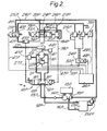
- Figure 2 illustrates a system for controlling such a second warp.
- the hydraulic and electronic components are identical to those of Figure 1 so that except for idcntifying the various components by the addition of the letter P, for port side, additional description is not thought necessary.
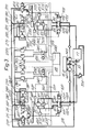
- Figure 3 illustrates a combined system for controlling two winches 1P and 1S.
- the prime mover 15 which now has multi-outputs, a single pilot line pump 31, a single pilot line 26, a single drain fluid line 25 and a single reservicr 17.
- the electronic unit 46 is shown in Figure as being common to both parts of the combined system. It is important to note that from a hydraulic functional aspect there is no comparison direct or otherwise of the tension conditions prevailing in the port half of the system with conditions prevailing in the starboard half of the system.
- the electronic circuit 46 is intended to provide a continuous monitoring of the instantaneous pressures or tensions in the two warps 2P and 2S and to relate these instantaneous values to a number of preselectable reference factors characteristic of certain operational factors involved in the trawling operation such as shooting, towing, hauling-in, so as to produce as and when required control signals for operating the solenoid valves particularly the valves 38P and 38S. lso the electronic circuit is required to respond to situations which interfere with the normal trawling operation and to produce suitable alarm signals when necessary.
- variable factors include the tension or pressures acceptable in the warps during shooting, towing, and hauling-in, the required length of the warps (the demand) whilst the relatively constant factors include a convertion factor to convert winch revolutions into warp length units in fathoms, the length of warp payed-out at which the unit 46 changes operation between manual and electronic operation, the warp length difference alarm (this being the length by which either warp must exceed demand length before initiating an alarm condition), the warp length difference this being a value which represents the length by which either warp must exceed the length demand for the associated winch pressure to increase to a maximum), and the length of warp that can be payed-out as a result of a fastener condition before initiating a corrective control function together with the extent of vrarp pay-out following a fastener condition before producing an alarm indication.
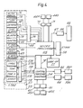
- the electronic circuit can conveniently be regarded as incorporating three major sections; a control and information display unit 53 which enables the presetting of the selectively variable reference values and also provides for the display of the operational state of the system; a warp pressure control sequencing unit 54, which compares the presettsble reference values relating to pressure of the warps with the instantaneous values thereof to previde inter alia control signals for the valves 38P and 38S; and a Microprocessor 55 having an associated program store 55.
- the microprocessor 55 serves to inter-relate control-wise the presettable factors relating to warp length and pressure with the instantaneous warp length and pressure conditions and the winch operation and with the substantially constant factors.
- the control and display unit 53 includes a first primary section 57 which enables selective presetting of the reference values of the warp thought necessary in the warps during the principal operation conditions arising during trawing namely, during shooting, normal towing, tow-plus towing, and shooting.
- the associated control enabling these settings are respectively indicated by the boxes 57A,57B1, 57B2 and 57C.
- These controls produce associated output signals each characteristic of the preset value which are fed through a suitable interface unit or units 58 along a bus 59 to the pressure sequencer and control unit 54 which latter is essentially a comparator circuit capable of comparing the references values with the continuously varying values and producing control outputs and indication outputs.
- the unit 54 has two further inputs which arc connected to receive via associated interface means 60;61 the output signals from the warp pressure detectors 45P and 45S.
- the unit 53 includes indicators 62;63 which respectively provide an indication of the associated instantaneous values of the port and starboard warp tensions, these indicators being connected to receive input from the unit 54.
- the latter produces the control signals for the solenoid valves 38P and 38S by way of associated signal amplifiers 64. These control signals serve to adjust the settings of the valves 38P and 38S and thus the operational rate of the associated winches.
- the unit 53 also includes a manually settable function control switch unit 65 which enables the primary trawling conditions to be net into the control unit, these conditions being, shooting, normal towing, tow-plus and haul.
- the unit 65 is connected by a signal bus 66 to the microprocessor 55 which latter produces from the signals from the unit 65 control signal outputs which are fed via a bus 67 through an interface unit 68 to the various solenoid valves 20P,20S; 24P and 24S. In Figure 4 these valves are collectively represented by the block 69.
- the outputs from the winch revolutions counters 44P and 44S are applied via associated signal interface units 70 and 71 to the microprocessor 55.
- the unit 53 also includes controls 72,73 and 74 whereby the above defined factors warp demand, the length difference and the length difference alarm can be respectively selectively set into the microprocessor 55.
- the unit 53 induces a control 75 for setting the warp length value at which the system changes over between manual and automatic operation.
- Associated signal interface arrangements 76 are provided for the contrcls 72 to 75.
- the above mentioned relatively constant values are stored in a storage unit in the form of a look-up table 77 which affords storage facilities for factors such as winch revolutions to warp pay-out convertion ratio, the amount of warp to be payed-out during manual control, the length of warp to be payed-out during the first stage of a fastener condition, the length of warp to be payed-out during the alarm stage of fastener communl.
- a control signal bus 78 is provided between the microprocessor 55 and the pressure sequencer circuit 54.
- the unit 53 also includes an alarm unit 79 associated with the fastener control arrangements and is actuated by signals from the microprocessor 55.
- the unit 53 for convenience provides a continuos visual display in digital form 80 of the amount of the starboard warp actually payed out.
- the facility is provided whereby the digital display 80 can be used to display the instantaneous valuse of the following factors this display being in cyclic form.
- This facility is controlled by a switch (not shown).
- the factors include port warp length; starboard length difference; port length difference; wineh revolutions devisor; auto/manual changeover length; length difference alarm; length difference; length demand and starboard length.
- the microprocessor used in the above discussed electronic unit is a Fairchild Semiconductor Inc. Micromachine F8 Series Microprocessor and includes a central processor unit F3850, an F8 program storage unit which includes F2708 programmable read only memories and an F8 static memory interface unit such as required in any particular installation.
- the prime mover 15 is set into operation thereby to drive the pumps 14S and 31S.
- valve 23S For the purposes of manual control the valve 23S is set into its ON position in which the control line 25S is connected to the relief valve 22S.
- the particular setting of the valve 23S determines the pressure at which the valve 23S operates to relieve pressure at the motor 3S.
- the valve 10S is set to the first ON position in which the connections 9S,11S, and 8S, 12S are operationally coupled so that the high pressure fluid is delivered to the pump31S in the direction that enables the warp 2S to be payed-out.
- the amount of warp payed-out is indicated by the warp length indicator 44S. Since the system is under manual control the reading will be in the form of a visual indication or record.
- valve 19S If it is required to operate the system from an alternative positionto that at which the valve 10S is sited the valve 19S is used. In practice, the valve 1CS would be sited adjacent to the winch installation of the vessel and the valve 19S would be located in the bridge housing or the like.
- the valve 19S is such that the pilot line pressure can be applied to one side or the other of the valve 103 by way of fluid lines 36S and 37S to cause operation of the valve from its neutral position to a selected one of its two ON settings or positions.
- valve 19S is operated in the reverse direction so that the pilot line pressure is applied to the line 37S and not the line 36S thereby causing the resetting of the valve 10S into its warp haul-in setting.
- the relief valve 22S operates to ailow the pressurised fluid to be bypassed relative to the motor.
- the manual control is restricted to use when lowering the trawl into the water and the paying -out of a short length of warp sufficient to ensure that the trawl is clear of the vessel.
- the manual control is used during the final stages of hauling-in the warps and the removal of the trawl from the water.
- the main shooting, towing and hauling operations are effected under the control of the electronic unit 46.
- the initial stages are effected manually as above described, after which the electronic unit 46 is switehes ON by operating the function switch 65.
- the operator sets into the unit the vorious varisbls factors mentioned sbove, i.e., the varlus pressure levels for ahoot, towing snd haul and the warp demand.
- a lso the relevent length differnce factors are set.
- the pressure sequencing unit 54 then operates thereby continuously comparing, the outputs of the warp pressure transducers 45P and 45S with the preset values and the microprocessor willbe operating upon the outputs from the winch revolution indicators 44P and 44S in relation to the various other factors specified by the operator and those effectively permanently set into the unit, whereby the operational conditions prevailing in each warp are separately monitored and controlled by reference to the standard, dummy or reference conditions set-up in the electronis unit.
- the control of either warp is essentially completely separate and independent of the control of the other warp in that the control of the conditions in one warp do not require or involve any reference or comparison with the conditions in the other warp.
- control of a warp is carried out by comparing the operational conditions therein with a reference value of a dummy set of values simulating desired conditions.
- control action being effected, at any one instant of time, in relation to one warp may well be completely opposite to the control action being effected at the other warp.
- the operation of the pressure sequencing unit 54 produces independent control signals which are respectively applied to the valves 38S and 38P by way of the lines 49S and 49P.
- the microprocessor 55 produces independent signals along the output bus 67 to the solenoid group 68. That is in relation to Figures 1 to 3, along the lines 48P, 48S to operate the valves 24P, 24S, and along the lines 47P,77S to operate the valves 20P, 20S.
- valve pairs 38P,24P and 38S, 24S connects the pilot line 25 by way of these asso associated valve pairs with the relief valves 22P,22S thereby to set the operaticnal pressures of the motors 3P, 3S.
- the operation of the valves 20P, 20S applies pilot pressure to the respective hydraulic line 37P or 37S by way of the associated selector valves 43P, 43S so that a higher fluid pressure is produced in the lines 37P,37S as compared with the pressure in the lines 35P, 36S. Consequently each directional control valve 10P, 10S is set into the heave or haul position for the associated motor 3P, 3S.
- the electronic circuit is continuously monitoring the amount of warp actually payed-out in each case with the preset requirements.
- the instantaneous pressure readings of the transducer units 45P,45S are continuously compared by the comparator, circuits in the control unit 54 with the values preset into the system by the operator to ensure that the individual pressure conditions in each warp are being maintained according to the preset reference levels
- the electronic unit 46 produces a variation in the signel applied to the relevent control valve 38P, 38S so as to vary the relief pressure setting thereby to change the rate at which the associated winch is able to pay out warp.
- the electronic unit will be monitoring the port and starboard side pressure and will be comparing the port signal with the reference and sending an error signal to the associated port valve 38P, and comparing the starboard signal with the reference and sending an error signal to the associated starboard valve 33S.
- the combined effect of the procedure is the separately equalise the port pressure with the reference and the starboard pressure with the reference whereby port pressure equals starboard pressure equals reference pressure.
- the electronic unit effects this by responding to the detection of a predetermined difference between these two factors and producing a variation i.e., increase in the pressure settings of the valves 38P and 38S thereby reducing rate of warp pay-out.
- a revolution responsive device (not shown) is provided for limiting the rate of rotation of the winches.
- the device is arranged to feed error signals to the port and starboard valves 38P and 388.
- valves 38P and 38S The variation in the setting of the valves 38P and 38S is maintained until the tension in each warp is attains a preset towing pressure and the required amount of warp has been payed-out.
- control unit is then set to the operational conditions relating to towing. This is the TOW condition.
- control valve associated with the warp with the increased tension will be adjusted in the opposite sense so as to pay-out more warp to accommodate the vessel turing circle.
- control unit continuously adjusts the warp pay-out or hauling-in by monitoring the tension whereby by the time the vessel is moving along its new heading the warps have been returned to their original conditions.
- the control system incorporates an obstruction correction and clearing control function which is automatically initiated whenever the trawl or warps become fouled by an obstruction.
- This control function is based upon the fact that if one of the warps becomes fouled the tension therein increases.
- the electronic unit 46 allows a preset length of the warp involved to be payed-out. The purpose of this is to ascertain whether the resulting slackness roduced in the warp will allow the warp to free itself or the trawl to free itself from the obstruction.
- the control unit 46 will increase the control setting of the relevent valve 38P or 38S so that an increased tension is allowed in the system.
- the electronic unit 46 responds to this fall in tension by adjusting the settings of the valves 38P and 38S to restore the previous levels of tension and th.s the required TOW condition.
- the electronic unit 46 is set to an operational condition termed TOW PLUS. In this setting of the unit increases the flow levels for the winch motors so that more power is available to maintain the desired setting of the trawl.
- the electronic control unit When it is required to haul in the trawl the electronic control unit is switched to the HAUL condition. When in this condition the control valves 38P and 3dS are reset so that the operating pressure for the winch motors 3P and 3S is at a relatively high value thereby enabling the winches to haul-in the warps and the trawl.
- control . unit 46 is continuously monitoring the tension conditions within the warps and effecting the above discussed control functions in relation to the instantaneous tensions in the warps. Thus, throughout the haul operation the winding-in of the warps is maintained uniform.
- the HAUL process continues until the trawl is returned to a predetermined distance from the wessel. In practice, this will be the position corresponding to the amount of the warps payed-out at the end of the manual shooting procedure.
- the electronic unit automatically reverts to manual mode and the solenoid operated-valves all return to their initial settings as shown in the Figures 1 to 3.
- valves 10P and 10S are returned to their neutral setting and the valves 24P and 24S are returned to their settings which enable manual control.
- the trawl is hauled aboard by the appropriate operation of the manually controlled valves 23P and 23S and 10P and 10S.
Landscapes
- Life Sciences & Earth Sciences (AREA)
- Environmental Sciences (AREA)
- Animal Husbandry (AREA)
- Biodiversity & Conservation Biology (AREA)
- Engineering & Computer Science (AREA)
- Mechanical Engineering (AREA)
- Looms (AREA)
- Fluid-Pressure Circuits (AREA)
- Lifting Devices For Agricultural Implements (AREA)
Applications Claiming Priority (4)
| Application Number | Priority Date | Filing Date | Title |
|---|---|---|---|
| GB2682378 | 1978-06-13 | ||
| GB7826823 | 1978-06-13 | ||
| AU53708/79A AU5370879A (en) | 1978-06-13 | 1979-12-12 | Pressure control of dual hydraulic systems |
| ZA00796786A ZA796786B (en) | 1978-06-13 | 1979-12-14 | Control systems for hydraulically operated circuits or systems |
Publications (2)
| Publication Number | Publication Date |
|---|---|
| EP0006333A2 true EP0006333A2 (de) | 1980-01-09 |
| EP0006333A3 EP0006333A3 (de) | 1980-01-23 |
Family
ID=27154884
Family Applications (1)
| Application Number | Title | Priority Date | Filing Date |
|---|---|---|---|
| EP79301089A Withdrawn EP0006333A3 (de) | 1978-06-13 | 1979-06-08 | Bedienungssystem für hydraulisch wirkende Einheiten oder Systeme |
Country Status (6)
| Country | Link |
|---|---|
| US (1) | US4323222A (de) |
| EP (1) | EP0006333A3 (de) |
| AU (1) | AU5370879A (de) |
| ES (2) | ES481480A0 (de) |
| NO (1) | NO791917L (de) |
| ZA (1) | ZA796786B (de) |
Cited By (1)
| Publication number | Priority date | Publication date | Assignee | Title |
|---|---|---|---|---|
| EP0079069A3 (de) * | 1981-11-07 | 1985-10-16 | BROWN, BOVERI & CIE Aktiengesellschaft | Verfahren zur Regelung der Haupttrommeln eines Hecktrawlers |
Families Citing this family (8)
| Publication number | Priority date | Publication date | Assignee | Title |
|---|---|---|---|---|
| US4565334A (en) * | 1982-10-22 | 1986-01-21 | Kennecott Corporation | Electrohydraulic drive for process line winders, unwinders and other equipment |
| US4570245A (en) * | 1983-04-18 | 1986-02-11 | Western Geophysical Company Of America | Constant tensioner for a seismic marine cable |
| US4581723A (en) * | 1983-04-18 | 1986-04-08 | Western Geophysical Company Of America | Method for maintaining a constant tension on a seismic marine cable |
| US4636962A (en) * | 1983-05-24 | 1987-01-13 | Columbus Mckinnon Corporation | Microprocessor-controlled hoist system |
| US4720975A (en) * | 1986-05-15 | 1988-01-26 | Ramsey Winch Company | Control valve |
| GB8729481D0 (en) * | 1987-12-17 | 1988-02-03 | British Nuclear Fuels Plc | Pumps & pump handling apparatus |
| NO921796D0 (no) * | 1992-05-06 | 1992-05-06 | Karmoey Winch As | Anvendelse av en passiv kompenseringsanordning |
| US8613426B1 (en) | 2009-12-14 | 2013-12-24 | L.E. Myers Co. | Power line puller control package |
Family Cites Families (10)
| Publication number | Priority date | Publication date | Assignee | Title |
|---|---|---|---|---|
| DE1161401B (de) * | 1961-05-23 | 1964-01-16 | Kampnagel Ag Vormals Nagel & K | Steuereinrichtung fuer Hebezeugtriebwerke zur Regelung auf lasthaltende Nullstellung |
| BE673453A (de) * | 1965-02-11 | 1966-04-01 | ||
| FR1525882A (fr) * | 1966-02-09 | 1968-05-24 | Inst Francais Du Petrole | Procédé d'ancrage d'une installation flottante au moyen d'amarres à tension contrôlée |
| FR1549187A (de) * | 1967-02-10 | 1968-12-13 | ||
| GB1424665A (en) * | 1972-02-04 | 1976-02-11 | Secretary Trade Ind Brit | System for controlling the position of a moored floating vessel |
| NO142956C (no) * | 1972-04-18 | 1990-11-14 | Hydraulik Brattvaag As | Hydraulisk system for to hydrauliske vinsjer, saerlig for traalvinsjer. |
| GB1464932A (en) * | 1974-11-22 | 1977-02-16 | Hydraulik Brattvaag As | Controlling oceanic trawls |
| DE2455829C2 (de) * | 1974-11-26 | 1984-08-09 | Aktieselskabet Hydraulik Brattvaag, 6270 Brattvaag | Hydrauliksystem für zwei zusammenwirkende Schleppnetzwinden für Fangschiffe |
| DE2507947A1 (de) * | 1975-02-25 | 1976-09-02 | Orenstein & Koppel Ag | Steuerungseinrichtung fuer zwei windenmotoren fuer verbundantriebe |
| GB1589769A (en) * | 1976-12-14 | 1981-05-20 | Secretary Industry Brit | System for controlling the position of a tethered floating vessel |
-
1979
- 1979-06-08 EP EP79301089A patent/EP0006333A3/de not_active Withdrawn
- 1979-06-08 NO NO791917A patent/NO791917L/no unknown
- 1979-06-12 US US06/047,739 patent/US4323222A/en not_active Expired - Lifetime
- 1979-06-12 ES ES481480A patent/ES481480A0/es active Granted
- 1979-12-12 AU AU53708/79A patent/AU5370879A/en not_active Abandoned
- 1979-12-14 ES ES486898A patent/ES486898A1/es not_active Expired
- 1979-12-14 ZA ZA00796786A patent/ZA796786B/xx unknown
Cited By (1)
| Publication number | Priority date | Publication date | Assignee | Title |
|---|---|---|---|---|
| EP0079069A3 (de) * | 1981-11-07 | 1985-10-16 | BROWN, BOVERI & CIE Aktiengesellschaft | Verfahren zur Regelung der Haupttrommeln eines Hecktrawlers |
Also Published As
| Publication number | Publication date |
|---|---|
| AU5370879A (en) | 1981-06-18 |
| US4323222A (en) | 1982-04-06 |
| ES8101845A1 (es) | 1980-12-16 |
| ZA796786B (en) | 1981-09-30 |
| ES486898A1 (es) | 1980-06-16 |
| NO791917L (no) | 1979-12-14 |
| ES481480A0 (es) | 1980-12-16 |
| EP0006333A3 (de) | 1980-01-23 |
Similar Documents
| Publication | Publication Date | Title |
|---|---|---|
| JP3869843B2 (ja) | トロール曳網装置およびその方法 | |
| US4323222A (en) | Control systems for hydraulically operated elements circuits or systems | |
| US20070041272A1 (en) | Control system for positioning of marine seismic streamers | |
| DE102011050857B4 (de) | Verfahren zum Ausgleichen eines Lastmoments | |
| AU2009208095A8 (en) | Apparatus and method for automatically adjusting the sail surface exposed to the wind | |
| US5376933A (en) | Trawl cable vibration meter | |
| DE102005050240B3 (de) | Einrichtung und Verfahren zum Steuern von Trimmklappen eines Wasserfahrzeugs, sowie Wasserfahrzeug mit einer entsprechenden Einrichtung | |
| GB2027947A (en) | Control system for hydraulically operated elements or systems | |
| US4242815A (en) | Suction pipe position control | |
| JPS61196030A (ja) | ドラグサクシヨン浚渫船の浚渫自動制御装置 | |
| EP0044724A1 (de) | Verfahren zum Öffnen, Schliessen und Rotieren von festen Segeln auf Schiffen | |
| US4305571A (en) | Means for regulating two trawl winches | |
| NO153563B (no) | Anordning for aa styre hastigheten til et skip forsynt med en styrbar vripropell. | |
| EP2377756B1 (de) | Beurteilung der Schiffsdynamik | |
| GB2057837A (en) | Method and apparatus for controlling a harvesting combine | |
| JP3413806B2 (ja) | 漁船の曳網監視方法およびその装置 | |
| DE2801080C2 (de) | Verfahren zum Baggern mittels eines Schneidkopfsaugbaggers und Schneidkopfsaugbagger hierzu | |
| DE2247457C3 (de) | Verfahren zum Steuern oder Regeln des Saugvorgangs eines Schleppkopf saugbaggers zum Aufsaugen einer Baggergut-Wasser-Suspension, und Schleppkopfsaugbagger hierfür | |
| JPS6259193A (ja) | 水中航走体制御用ケ−ブル付きロボツトシステム | |
| JP3796247B2 (ja) | トロール網の曳網方法と曳網装置 | |
| JP5036365B2 (ja) | 曳航体の深度制御方法とその装置 | |
| DE2455829C2 (de) | Hydrauliksystem für zwei zusammenwirkende Schleppnetzwinden für Fangschiffe | |
| JPH037519A (ja) | 自動魚釣装置 | |
| JPH0253009B2 (de) | ||
| CA2060443A1 (en) | Trawl cable vibration meter |
Legal Events
| Date | Code | Title | Description |
|---|---|---|---|
| PUAI | Public reference made under article 153(3) epc to a published international application that has entered the european phase |
Free format text: ORIGINAL CODE: 0009012 |
|
| PUAL | Search report despatched |
Free format text: ORIGINAL CODE: 0009013 |
|
| AK | Designated contracting states |
Designated state(s): BE DE FR NL SE |
|
| AK | Designated contracting states |
Designated state(s): BE DE FR NL SE |
|
| 17P | Request for examination filed | ||
| STAA | Information on the status of an ep patent application or granted ep patent |
Free format text: STATUS: THE APPLICATION IS DEEMED TO BE WITHDRAWN |
|
| 18D | Application deemed to be withdrawn |
Effective date: 19820302 |
|
| RIN1 | Information on inventor provided before grant (corrected) |
Inventor name: WILSON, JOHN JEFFREY Inventor name: DEMPSTER, DAVID FRASER |