EP0010085B1 - Eine schutzvorrichtung gegen strassenschmutz für mit kotflügel ausgerüstete fahrzeuge - Google Patents
Eine schutzvorrichtung gegen strassenschmutz für mit kotflügel ausgerüstete fahrzeuge Download PDFInfo
- Publication number
- EP0010085B1 EP0010085B1 EP78900045A EP78900045A EP0010085B1 EP 0010085 B1 EP0010085 B1 EP 0010085B1 EP 78900045 A EP78900045 A EP 78900045A EP 78900045 A EP78900045 A EP 78900045A EP 0010085 B1 EP0010085 B1 EP 0010085B1
- Authority
- EP
- European Patent Office
- Prior art keywords
- mudguard
- airstream
- wheel
- splash
- channel
- Prior art date
- Legal status (The legal status is an assumption and is not a legal conclusion. Google has not performed a legal analysis and makes no representation as to the accuracy of the status listed.)
- Expired
Links
- 230000001012 protector Effects 0.000 claims description 12
- 239000000428 dust Substances 0.000 claims description 10
- 230000036961 partial effect Effects 0.000 claims description 7
- 241000446313 Lamella Species 0.000 claims description 2
- 230000003993 interaction Effects 0.000 claims 1
- 230000000694 effects Effects 0.000 abstract description 19
- 230000033001 locomotion Effects 0.000 abstract description 3
- 239000002245 particle Substances 0.000 description 24
- XLYOFNOQVPJJNP-UHFFFAOYSA-N water Substances O XLYOFNOQVPJJNP-UHFFFAOYSA-N 0.000 description 12
- 239000013598 vector Substances 0.000 description 11
- 239000003595 mist Substances 0.000 description 6
- 230000003068 static effect Effects 0.000 description 5
- 230000000712 assembly Effects 0.000 description 2
- 238000000429 assembly Methods 0.000 description 2
- 238000013016 damping Methods 0.000 description 2
- 230000001419 dependent effect Effects 0.000 description 2
- 238000010586 diagram Methods 0.000 description 2
- 230000000670 limiting effect Effects 0.000 description 2
- 238000000926 separation method Methods 0.000 description 2
- 230000003213 activating effect Effects 0.000 description 1
- 230000005540 biological transmission Effects 0.000 description 1
- 239000000463 material Substances 0.000 description 1
- 239000000203 mixture Substances 0.000 description 1
- 230000002829 reductive effect Effects 0.000 description 1
- 230000003014 reinforcing effect Effects 0.000 description 1
- 230000008439 repair process Effects 0.000 description 1
- 230000000717 retained effect Effects 0.000 description 1
- 238000012216 screening Methods 0.000 description 1
Images




Classifications
-
- B—PERFORMING OPERATIONS; TRANSPORTING
- B62—LAND VEHICLES FOR TRAVELLING OTHERWISE THAN ON RAILS
- B62D—MOTOR VEHICLES; TRAILERS
- B62D25/00—Superstructure or monocoque structure sub-units; Parts or details thereof not otherwise provided for
- B62D25/08—Front or rear portions
- B62D25/16—Mud-guards or wings; Wheel cover panels
- B62D25/18—Parts or details thereof, e.g. mudguard flaps
-
- H—ELECTRICITY
- H01—ELECTRIC ELEMENTS
- H01S—DEVICES USING THE PROCESS OF LIGHT AMPLIFICATION BY STIMULATED EMISSION OF RADIATION [LASER] TO AMPLIFY OR GENERATE LIGHT; DEVICES USING STIMULATED EMISSION OF ELECTROMAGNETIC RADIATION IN WAVE RANGES OTHER THAN OPTICAL
- H01S5/00—Semiconductor lasers
- H01S5/20—Structure or shape of the semiconductor body to guide the optical wave ; Confining structures perpendicular to the optical axis, e.g. index or gain guiding, stripe geometry, broad area lasers, gain tailoring, transverse or lateral reflectors, special cladding structures, MQW barrier reflection layers
- H01S5/22—Structure or shape of the semiconductor body to guide the optical wave ; Confining structures perpendicular to the optical axis, e.g. index or gain guiding, stripe geometry, broad area lasers, gain tailoring, transverse or lateral reflectors, special cladding structures, MQW barrier reflection layers having a ridge or stripe structure
- H01S5/227—Buried mesa structure ; Striped active layer
-
- H—ELECTRICITY
- H01—ELECTRIC ELEMENTS
- H01S—DEVICES USING THE PROCESS OF LIGHT AMPLIFICATION BY STIMULATED EMISSION OF RADIATION [LASER] TO AMPLIFY OR GENERATE LIGHT; DEVICES USING STIMULATED EMISSION OF ELECTROMAGNETIC RADIATION IN WAVE RANGES OTHER THAN OPTICAL
- H01S5/00—Semiconductor lasers
- H01S5/02—Structural details or components not essential to laser action
- H01S5/0206—Substrates, e.g. growth, shape, material, removal or bonding
- H01S5/0207—Substrates having a special shape
Definitions
- the present invention relates to a splash protection assembly for vehicles with mudguards, comprising means arranged between the wheel of the vehicle and the mudguard for lessening the spread of dust and splash as a result of the vehicle travel, said means including at least one guide member in the airstream occurring as a result of the rotation of the wheel and extending substantially across the entire width of the mudguard and being provided with one guide surface to form at least a part of a channel for an airstream along the inside of the mudguard.
- splash protection assemblies In the great majority of these known splash protection assemblies, the accepted theory is that the water and dust mist occurring behind a vehicle in movement can be eliminated by preventing splashes from impinging on different parts of the inside of the mudguard and mudflap where they are disintegrated into smaller drops forming a mist at the side and behind the vehicle.
- the term "splash” is intended here to denote the portion of the splash which is generated by water and particles being entrained in the tyre tread and tangentially flung off by centrifugal force from the tyre.
- Heavier particles will thus be thrown off from the tyre relatively immediately, while water and smaller particles are thrown off at a later time, due to the suction effect occurring when the tyre spread expands after contact with the road surface. This time is dependent on the size of the mud particle, adhesion force between the tyre and the particle and the circumferential speed of the wheel. With low circumferential speed, the adhesion force dominates, and the majority of the muddy water is retained in the tyre for the greater part of the rotation.
- the adhesion force is overcome by the centrifugal force and there is a separation of particles in the direction of rotation of the tyre, the heavier particles being separated first while lighter particles are separated later, at times depending on the weight of the particle, the adhesion force and the centrifugal force.
- the screening assemblies of the prior art are formed in such a way that mainly heavier particles are prevented from being thrown off towards a following vehicle.
- This effect is also obtained by different kinds of so-called "mudflaps", i.e. the splash protectors of flexible material which are usually fixed to the extension of the mudguard behind the tyre and towards the road surface.
- the screen has been placed as close to the circumference of the wheel as possible, and has been directed so that the particles thrown off in front of the screen impinge on it and are partially guided back down towards the.'road surface in a spread-out condition.
- The- particles of muddy water which are thrown off behind the screen will thus, as previously, give rise to a mist of water around the vehicle.
- This function is also strived for in newer types of mudflaps, and it therefore consists of a plurality of baffles which guide the heavier particles in the splash down towards the road surface. All these known structures are, however, only intended to limit the spread of the heavier particles in the splash and not the part which is thrown off later, and which gives rise to the water mist behind and at the sides of the vehicle.
- DE-A 880 555 discloses a splash protection assembly for vehicles, especially motorcycles, in the form of a splash plate serving as an impinging surface for the splash flowing out from the forward and upper portion of the mudguard, where the drops are then redirected by the airflow and thrown to the sides so that they impinge on the legs of the driver.
- a guiding screen is placed between the wheel and the inside of the mudguard to form an impinging surface for the splash, which is thereby forced by the airflow back into the mudguard instead of being sprayed out in front of it.
- this arrangement does not prevent splash from flowing out laterally of the mudguard.
- DE-A 227 760 relates to a splash protection assembly for lessening the spread of dust and splash as a result of the vehicle travel in which the wheel is located in a duct collecting housing which covers the wheel on the sides and on the top quite closely and widens laterally in its rear portion in which it is provided with an opening to permit the air collected in the mudguard to be discharged.
- the rear opening can be covered by a filter in order to prevent the dust from escaping through the opening.
- vanes could be located in the housing. The dust which has been separated by the filter and by the vanes should be collected at the floor of the housing and is permitted to escape in small lumps through the openings of the floor down on the road.
- the vanes extending across the mudguard do not form part of a channel for an airstream along the inside of the mudguard since this channel in fact is destroyed by the opening permitting the air collected in the mudguard to flow out freely in the open air.
- the airstream along the inside of the mudguard is of vital importance in the action of redirecting the airstream occurring as a result of the rotation of the wheel and the thus formed splash.
- the splash protection assembly is based on new knowledge of the complex aerodynamical conditions giving rise to splash wake, and is substantially characterized in that said guide member comprises a guide body with three guide surfaces, a first of which is arranged to form said part of the channel, a second forming the lower side of the guide body and adapted to redirect a part of the airstream occurring as a result of the rotation of the wheel and the thus formed splash, and a third guide surface forming a leading edge together with the second guide surface, said leading edge being directed towards the airstream occurring as a result of the rotation of the wheel and the thus formed splash and splitting this airstream into two partial airstreams, a first of which is guided by the second guide surface, and that the third guide surface together with the first guide surface form the upper side of the guide body and are adapted to redirect the second partial airstream so that the two partial airstreams enter the channel substantially in parallel with one another and with the airstream in the channel.
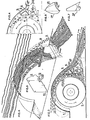
- a heavily turbulent zone 10 between the mudguard and the vehicle wheel as a result of the airflow being opposed in direction to the airstream generated by the splash and rotation of the wheel, thus giving rise to zone 10 at increased pressure, from which air eddies out at the sides towards zones with lower pressure as is indicated in Fig. 2 by the numeral 11.
- the zones with lower pressure occur, i.a. by the airflow generating a certain suction effect, the air mixed with dust or particles of water and flowing out from the mudguard being spread sideways and behind the vehicle under the action of passing air.
- a mudflap 5 is placed conventionally at the rear edge of the mudguard to prevent larger particles from being thrown directly towards a following vehicle.
- a conventional mudguard with a mudflap of this kind reinforces the spreading effect of dust and water particles, however, since a turbulent zone is formed behind the mudflap.
- Conventional mudguards have also a certain aerodynamically braking effect on the vehicle and attempts are generally made to reduce this effect by placing the mudguard closer to the wheel. This measure also contributes to reinforcing the spread of water and dirt mist round the vehicle.
- the turbulent excess pressure zone 10 moves counter to the direction of rotation of the wheel as the circumferential speed of it increases, which has to do with the centrifugal force increasing with increasing circumferential speed, while the adhesion force is substantially constant and independent of the speed, as has already been pointed out in the general portion of this description.
- the invention is based on the desire to prevent the occurrence of the static excess pressure zone formed with a conventional mudguard, and which can occur by not closing in the opposing streams of air between the mudguard and the wheel, but separating them with the help of a guide member 3, with its side facing towards the muaguard, together with the inside of the mudguard or with a further guide member, forming a channel 9 between the zone at increased air pressure H and a zone L, with lower air pressure, situated downstream of the excess pressure zone H in the airflow direction.
- a natural expansion path is hereby achieved for the air between both pressure zones simultaneously as the dynamic pressure of the airflow is utilized to deflect the opposing airstream polluted with splash, and coming from the wheel, to force it back again towards the road surface in a collected stream of air which can be prevented by different means from spreading to any notable extent.
- the Figures 3, 4 and 6 show how the air currents interact when a guide body 3 has been introauced between the wheel and mudguard, and how effectively this body separates the opposing air currents.
- the air currents are mixed, the speed of the airstream generated by the splash has been substantially reduced while the airflow has a substantially greater dynamic pressure, resulting in that the first mentioned airstream is entrained, forces into the channel 9 and down towards the road surface.
- the suction effect can be improved by having a gap 7 between the mudflap 5 and the guide body 3, which can be given a configuration varying in different ways to increase the effect of the assembly.
- the excess pressure zone H occurs firstly by the action of aerodynamic factors A, secondly by the kinetic factors K and thirdly by the mixture of these factors A and K.
- the bottom edge 8a of the mudguard can be given a configuration such that the exit flow vector S meets with a specific concentration and force the airflow vector D which varies directly as the circumferential speed of the wheel. These vectors should meet each other at an angle which is less than 90° and subsequently continue in a resulting direction R with an angle y to the road surface which will be proportional to the size of both vectors S and D.
- the effectiveness of the guide body 3 is dependent on its proportions along the x-axis as well as the y-axis, where "y-axis" relates to the distance of the body above the rotational axis of the wheels, and this distance should be so adjusted that the upwardly directed air currents K will be sufficiently weakened for deflection towards the inlet of the channel 9.
- the dimensioning of the guide body 3 along the y-axis can vary, depending on what other elements are used together with the guide body in the splash protection assembly.
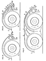
- a baffle 4 can be used, e.g. as is apparent from Fig. 10, the opposing airstreams A and AK being thus even more effectively separated to prevent the occurrence of a static excess pressure zone.
- the extension of the guide body along the horizontal line going through the wheel axis is its extension along the x-axis, which gives the distance from the circumference of the wheel to the outlet of the channel 9 at the same time.
- the extension of the guide body along the x-axis should be adjusted so that passing currents, and especially the lower current passing through the gap 7, will be substantially free from turbulence. This effect can also be obtained by adjusting the form of the mudflap 5 as shown in Figs. 40-45.
- the guide body can be given different configurations to improve its coaction with the other members included in the assembly.
- its surface 3a facing towards the wheel can be given a curved form, as is apparent from Fig. 8, so that the upward airstream K is partly separated more effectively from the airstream D caused by larger particles, and partly deflected more gently for connecting to the main airstream through the channel 9.
- From the other surfaces 3b and 3c it can be seen how the desired effect of preventing turbulence can be obtained at the same time as the different air currents passing over the surfaces of the guide body are effectively mixed.
- Fig. 7 illustrates how the surface 3d of the guide body 3 can be varied partly to force the airstream KD towards the road surface, and partly for apportioning the air currents along both these adjacent side surfaces.
- a baffle 4 can be introduced to further improve separation between the two opposing airstreams AK and A to reduce the risk of static pressure increase when both air currents are mixed.
- the flow rate is furthermore increased in the channel parts 9a and 9, which in turn improves the ejector effect for the airstreams AK and K, when these are caused to enter substantially parallel to the main airstream A in the channel 9.
- Such an arrangement results in that the vector S' becomes greater than the vector S in Fig. 4, in turn signifying a more efficient damping effect on the vector D, since the angle y' of the resultant vector R' to the road surface will be greater than the angle y in Fig. 4.
- the configuration of the baffle can be varied, as is apparent from Figs. 13 and 14, particularly the curve of its front edge and its radius, depending on its location between the mudguard and wheel.
- the amount of the leading edge of the baffle is bent downwards is denoted by the dimension z in Fig. 10, and the leading edge should be placed at a height of y" from the rotational axis of the wheel, which corresponds to the lower activating zone of the airstreams A.
- the length of the baffle 4 can also be varied, depending on the shape and size of the mudguard; the portion coinciding with the direction xy should then be adjusted to the dimensions of the channel 9 so that the channel functions as effectively as possible.
- Figs. 13 and 14 it is indicated how the configuration of the baffle can be varied and how the course of the flow can be controlled by introducing a plurality of baffles with different configurations and different locations.
- Figs. 15, 16 and 17 show how the guide body and baffle can be given different configurations for providing airstreams suited to the exterior conditions.
- Fig. 16 shows how the baffle can be formed with different configurations on both its defining surfaces.
- Fig. 17 shows an application of the baffle and guide body to tandem double wheels.
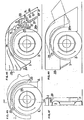
- the guide body 8 is formed cylindrically and mounted on a shaft 16 carried by two arms 17, in turn pivotably mounted on the mudguard 1.
- the cylindrical body 8 can thus be brought into engagement with the vehicle wheel 2, e.g. by the arms 17 being actuated by a setting means 20, which can be either manually or automatically actuated.
- a setting means 20 which can be either manually or automatically actuated.
- the cylindrical body is driven by the vehicle wheel, utilizing friction, at substantially the same circumferential speed as the wheel, and as a result of the centrifugal force it will redirect the trajectory of a portion of the particles loosened from the wheel, i.a. because of the frictional engagement. Furthermore, the contact between the cylindrical body and the wheel will, per se, loosen particles from the wheel and throw them in a direction influenced by the structure of the circumference of the body. As shown in Figs. 25-27, this surface can either be smooth or patterned in combination with a short-bristled brush-like covering, as indicated in Fig. 26, or with long bristles as indicated in Fig. 27.
- the particles loosened and thrown off by the body will be given a trajectory joining the main flow A through the channel 9 between the body and the mudguard 1.
- the body can be arranged together with one or more baffles 19, which facilitates and improves the redirection of the airstream and the particles loosened from the vehicle wheel, while the assembly can also be combined with stationary baffles 4, previously described.
- the arrangement with a cylindrical guide body can be suitably combined with a mudflap 5, of the kind described earlier, with a gap 7 between the body and the mudflap for the particles thrown off from the vehicle wheel. Since the rotation of the body counteracts these airstreams, a limiting baffle can be introduced between these flow directions to eliminate static pressure zones with the undesired consequences these have. From Fig. 22 it is also apparent that both arms 17 carrying the cylindrical body 8 can be displaced in grooves to enable the body to be movably mounted.
- outside airstreams can be utilized to increase the flow speed in the channel 9 between both pressure zones.
- These outside airstreams can be generated for example by an outer screen 20 located outside the mudguard, the former together with the mudguard 1 forming an outer channel with air intake 23 and one . or more outlets 24a and 24b.
- an auxiliary airstream is generated in the outer channel, and this airstream is introduced parallel to the main airstream in the inner channel 9, to reinforce it and give it an increase in velocity.
- the air intake 23 can either be formed as shown in Figs. 28 and 29, or also as indicated in Figs. 33 and 34, i.e.
- the outer channel can be provided with constrictions or other means increasing the ejector effect when the outer airstream is introduced into the channel 9 between the pressure zones.
- the mudguard can be provided with louvres 23d to allow air passage between these channels, before both airstreams are combined in the main channel between the pressure zones.
- FIG. 31 shows an alternative embodiment of the outer channel, where the air intake 23c is placed on the rear side of the mudguard and the channel is given a curved shape, while its outlet is formed with a constriction increasing air speed and improving mixing between the airstreams.
- the air speed can be increased by introducing a constricting orifice 25 in the outer channel 24.
- the shape of the mudflap is also important for achieving the technical effect sought in accordance with the invention.
- a turbulent zone occurs behind a conventional mudflap 5, counteracting the damping effect of the main airstream directed towards the road surface and thus injuring the effectiveness of the assembly.
- the mudflap 5 has been given a flow-controlling configuration, thus causing the turbulence behind it to diminish while at the same time a guide channel is formed between the guide body 3 and the guiding surface of the mudflap, which redirects the flow vector KD so that it is introduced gently and substantially parallel to the airstream through the main channel 9 between the pressure zones.
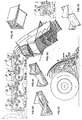
- splash protectors comprising a part 5, 5a, 5b or 5c, intended to serve as mudflap and attached between two side portions 26, 26a, 26b and 26c, limiting the inner airstream generated by splash from the airflow to lessen the risk of the splash being sucked out to the sides of the vehicle.
- the splash protector also comprises a guiding flange 27, 27a, 27b and 27c to guide the airstream in the main channel 9 between the pressure zones and prevent it from being disturbed by the merging airstream from the splash.
- the Figures also show how the mudflap can be shaped and brought to coact with the guide body 3 for obtaining the least possible turbulence in the area behind it.
- the "mudflap" can naturally be formed as a guide body, as indicated by dashed lines in Fig. 40 and full lines in Fig. 44.
- Figs. 35 and 36 show how a lamella or louvre type 5e of splash protector can be utilized in combination with an arrangement according to the invention.
- Louvre splash protectors are known per se, but have not achieved the desired effect since they only look after the heaviest particles in the splash, which after impinging on the louvres are thrown down onto the road surface in a spread-out condition. If an apparatus of the kind depicted in Figs. 35 and 36 is utilized, however, splash spread from the louvres is prevented because the splash impinging on the louvres is reflected into the main airstream in the channel 9 between the pressure zones, where the side pieces 26e effectively coact to keep the main stream collected before it is allowed to flow out freely from the outlet 6a.
- Fig. 36 is,a a perspective view of how air and splash flow through a splash flow through a splash protector according to the last mentioned embodiment.
- Figs. 46-49 show, i.a. how a splash protection assembly according to the present invention can be formed with movable side pieces 28 and 28a, pivotably mounted in the mudguard, e.g. about a shaft 29, and which can be retracted for removing the wheel or in conjunction with the bottom of the mudflap 5 knocking against an obstacle on the road surface.
- the airflow can cause water and dirt mist occurring between the wheel and the mudguard to be sucked out at the side past the edges of the mudguard and spread to the side of and behind the vehicle.
- the movable side pieces thus have the object of separating the airstream inside the mudguard from the airflow, thereby further reducing the risk of splash being spread out at the sides.
- the movable side pieces are suitably formed as extensions 28 of the side portions of the mudguard 1, either on the outside or inside thereof. These extensions must naturally be movable, primarily to allow simple removal of the vehicle wheel in conjunction with wheel changes or other repairs to the vehicle.
- Fig. 48 shows an inventive embodiment containing a plurality of the components accounted for in conjunction with the previous description of the Figures here.
- This splash protection assembly thus has a guide member in the form of a fixed guide body 3, as well as a movable guide body 8, for bringing into engagement with the vehicle wheel, and which is coupled via a transmission 32 to a fanwheel 31 intended to increase the flow speed through the channel between the guide body 3 and the baffle 4 immediately above it.
- the cylindrical guide body 8 can be brought to engage the vehicle wheel by means of a lever 33, pivotable in one direction under the action of a counterweight 34, there being a cable 35 connected to the lever for actuating it in the other direction.
- the cable can in turn be actuated manually or by a motor.
- the splash protection assembly according to this embodiment further comprises two baffles 4 and an outer channel 24, the latter having an air intake 23 and an outlet shaped for venturi effect to increase the flow speed in the inner channel 9.
- the forward part of the mudguard can also be provided with an air intake 23, further contributing to increasing the flow speed between the wheel and the mudguard, thus also contributing to increasing the effectiveness of the assembly.
- the assembly is further provided with a movable side piece 28a, formed with a part constituting an extension of the baffle 1 a and connecting thereto as well as to another part 27 which together with the mudflap 5f forms at least one extended portion 9a and 9b of the channel between both pressure zones.
Landscapes
- Physics & Mathematics (AREA)
- Engineering & Computer Science (AREA)
- Chemical & Material Sciences (AREA)
- Combustion & Propulsion (AREA)
- Transportation (AREA)
- Mechanical Engineering (AREA)
- Geometry (AREA)
- Condensed Matter Physics & Semiconductors (AREA)
- General Physics & Mathematics (AREA)
- Electromagnetism (AREA)
- Optics & Photonics (AREA)
- Body Structure For Vehicles (AREA)
Claims (15)
Applications Claiming Priority (2)
| Application Number | Priority Date | Filing Date | Title |
|---|---|---|---|
| SE7708063 | 1977-07-11 | ||
| SE7708063A SE407377B (sv) | 1977-07-11 | 1977-07-11 | Stenkskyddsanordning for fordon med stenkskermar |
Publications (2)
| Publication Number | Publication Date |
|---|---|
| EP0010085A1 EP0010085A1 (de) | 1980-04-30 |
| EP0010085B1 true EP0010085B1 (de) | 1983-02-09 |
Family
ID=20331851
Family Applications (1)
| Application Number | Title | Priority Date | Filing Date |
|---|---|---|---|
| EP78900045A Expired EP0010085B1 (de) | 1977-07-11 | 1979-02-14 | Eine schutzvorrichtung gegen strassenschmutz für mit kotflügel ausgerüstete fahrzeuge |
Country Status (5)
| Country | Link |
|---|---|
| US (1) | US4334694A (de) |
| EP (1) | EP0010085B1 (de) |
| DE (1) | DE2862173D1 (de) |
| SE (1) | SE407377B (de) |
| WO (1) | WO1979000039A1 (de) |
Families Citing this family (43)
| Publication number | Priority date | Publication date | Assignee | Title |
|---|---|---|---|---|
| US4445700A (en) * | 1981-10-23 | 1984-05-01 | Schroeder Warren C | Highway transport truck tire water splash shield |
| US4706981A (en) * | 1986-10-17 | 1987-11-17 | Dorwart Richard E | Vehicular spray dampening device |
| US4858941A (en) * | 1987-07-23 | 1989-08-22 | Becker John H | Tire spray control device |
| US5100177A (en) * | 1987-07-23 | 1992-03-31 | Becker John H | Tire spray control device |
| US4921276A (en) * | 1988-05-23 | 1990-05-01 | Morin Albert Z | Spray controlling fender |
| US5277444A (en) * | 1992-07-15 | 1994-01-11 | Transgard, Inc. | Vehicle water spray control devices |
| GB9216562D0 (en) * | 1992-08-04 | 1992-09-16 | Kay Roger | Devices for controlling spray from vehicles |
| US5489108A (en) * | 1992-11-13 | 1996-02-06 | Slade; Val | Flexible fender |
| US5375882A (en) * | 1993-01-11 | 1994-12-27 | Koch, Iii; Stanley G. | Mist suppressant panels for a vehicle and a method of suppressing mist |
| US5460411A (en) * | 1994-01-11 | 1995-10-24 | Air Fenders Ltd. | Fender for cooling tires and brakes and to control spray |
| IT1279132B1 (it) * | 1995-04-19 | 1997-12-04 | Dipartimento Di Energetica Del | Dispositivo per la riduzione della resistenza di forma dei veicoli. |
| WO1998022329A1 (en) * | 1996-11-18 | 1998-05-28 | Bjoerklund Jan E O | Device for exploiting surrounding mattercurrent |
| DE19819156B4 (de) * | 1998-04-24 | 2006-12-14 | Stephan Koch | Kraftfahrzeug |
| US6260911B1 (en) | 2000-02-16 | 2001-07-17 | John H. Becker | Air duct for cooling rotating tires |
| EP1268263B8 (de) * | 2000-03-30 | 2005-02-02 | Yvan Brulhart | Aerodynamischer stabilisator für kraftfahrzeuge |
| ITNU20010001A1 (it) * | 2001-01-29 | 2002-07-29 | Francesco Loddo | Idroespulsore ii |
| US6526336B2 (en) * | 2001-02-01 | 2003-02-25 | Invacare Corp. | System and method for steering a multi-wheel drive vehicle |
| US6799782B2 (en) * | 2002-08-08 | 2004-10-05 | International Truck Intellectual Property Company, Llc | Splash and spray suppressor |
| US20110214568A1 (en) * | 2003-03-12 | 2011-09-08 | Jeffrey Krantz | System and method for removing brake dust and other pollutants |
| JP4622312B2 (ja) * | 2003-08-26 | 2011-02-02 | トヨタ自動車株式会社 | 車両 |
| GB0407653D0 (en) * | 2004-04-03 | 2004-05-05 | Downes John A | Device for preventing vehicle wheel spray |
| US8608203B2 (en) * | 2004-04-03 | 2013-12-17 | Spraydown Limited | Spray prevention device |
| JP4229204B1 (ja) * | 2007-09-11 | 2009-02-25 | トヨタ自動車株式会社 | 車両用空力構造 |
| US8814253B1 (en) | 2011-04-21 | 2014-08-26 | Flowbelow, LLC | Aerodynamic quarter fender assembly and construction method |
| US8616571B2 (en) | 2011-08-23 | 2013-12-31 | Paccar Inc | Vehicle splash guards and adaptors therefor |
| JP5861320B2 (ja) * | 2011-08-29 | 2016-02-16 | トヨタ自動車株式会社 | 車両後部構造 |
| JP5931576B2 (ja) * | 2012-05-10 | 2016-06-08 | 小島プレス工業株式会社 | フェンダーライナ |
| US9394007B2 (en) * | 2012-10-31 | 2016-07-19 | Tai-Hsien Yen | Fender flare |
| HK1215229A1 (zh) | 2012-11-01 | 2016-08-19 | FlowBelow Aero, Inc. | 氣動系統和可調整流罩 |
| BR112015012838B1 (pt) * | 2012-12-03 | 2022-06-07 | Toyota Jidosha Kabushiki Kaisha | Estrutura de para-lama veicular |
| JP5983384B2 (ja) * | 2012-12-12 | 2016-08-31 | トヨタ自動車株式会社 | 車体後部構造 |
| US9120466B2 (en) * | 2013-03-15 | 2015-09-01 | Cnh Industrial America Llc | Scraper assembly for an off-road vehicle |
| JP5854021B2 (ja) | 2013-03-27 | 2016-02-09 | トヨタ自動車株式会社 | ホイルハウス後部構造 |
| US9284000B1 (en) | 2014-10-17 | 2016-03-15 | Paccar Inc | Vehicle splash guard |
| EP3271210B1 (de) * | 2015-03-20 | 2019-09-11 | Carrier Corporation | Hitze- und staubschild |
| WO2018085791A1 (en) | 2016-11-04 | 2018-05-11 | FlowBelow Aero, Inc. | Chassis mounted energy extraction and delivery system |
| US9783248B1 (en) * | 2017-02-22 | 2017-10-10 | GM Global Technology Operations LLC | Rear wheelhouse vent assembly and a vehicle |
| US10654529B2 (en) | 2017-06-24 | 2020-05-19 | FlowBelow Aero, Inc. | Aerodynamic systems and fairings with fairing caps |
| WO2019014503A1 (en) | 2017-07-12 | 2019-01-17 | FlowBelow Aero, Inc. | AERODYNAMIC TOOLBOX SET |
| US10882571B2 (en) | 2017-07-30 | 2021-01-05 | FlowBelow Aero, Inc. | Rotatable aerodynamic fairing system |
| US11072377B2 (en) | 2018-09-04 | 2021-07-27 | Lund, Inc. | Removable fairing |
| US11767064B2 (en) | 2021-01-12 | 2023-09-26 | FlowBelow Aero, Inc. | Spring-biased mud flap hanger with improved pivoting motion guidance |
| US11279326B1 (en) | 2021-05-07 | 2022-03-22 | Donald J. Siegel, Jr. | Debris removal device |
Family Cites Families (15)
| Publication number | Priority date | Publication date | Assignee | Title |
|---|---|---|---|---|
| DE644810C (de) * | 1937-05-13 | Adam Eberle | Kotfluegel fuer Kraftfahrzeuge | |
| DE191703C (de) * | ||||
| DE227760C (de) * | ||||
| GB190308689A (en) * | 1903-04-16 | 1904-04-16 | Auguste Froment | Improvements in or connected with Dust-guards and Mud-guards applicable for Removing Nails and the like from the Tyres of Road Vehicles. |
| GB191220020A (en) * | 1912-09-02 | 1913-09-02 | Richard Poore | Improvements in and relating to Mud Guards for Road Vehicles. |
| US1220494A (en) * | 1916-02-04 | 1917-03-27 | Harry J Butler | Mud-deflector. |
| CH84539A (de) * | 1919-04-11 | 1920-03-16 | Spaelti Mueller Fridolin | Staubfangvorrichtung an Fahrzeugen |
| CH155961A (de) * | 1931-03-18 | 1932-07-15 | Ellenberger Friedrich | Abstreifvorrichtung an Fahrzeugen. |
| DE880555C (de) * | 1951-11-23 | 1953-06-22 | Hans Westermeier | Spritzblech fuer Kraftfahrzeuge, insbesondere fuer das Vorderrad von Kraftraedern |
| FR1055386A (fr) * | 1952-05-03 | 1954-02-18 | Déviateur destiné à empêcher la boue de souiller les carrosseries des véhicules automobiles | |
| DK80735C (da) * | 1954-07-21 | 1956-03-19 | Marius Viggo Hansen | Anordning ved stænkskærme til køretøjer, navnlig motorkøretøjer. |
| DK81091C (da) * | 1954-12-29 | 1956-09-17 | Marius Viggo Hansen | Anordning ved stænkskærme til køretøjer, navnlig motorkøretøjer. |
| DK106367A (de) * | 1964-01-20 | |||
| DE2025519A1 (de) * | 1970-05-26 | 1971-12-09 | Graf, Dipl.-Ing., Rupprecht, 6470 Büdingen | Schmutzabweiser |
| DE2524344C3 (de) * | 1975-06-02 | 1978-09-14 | Otto 8771 Schollbrunn Leimeister | Kotflügel für Kraftfahrzeuge |
-
1977
- 1977-07-11 SE SE7708063A patent/SE407377B/sv not_active IP Right Cessation
-
1978
- 1978-07-11 DE DE7878900045T patent/DE2862173D1/de not_active Expired
- 1978-07-11 WO PCT/SE1978/000016 patent/WO1979000039A1/en not_active Ceased
- 1978-07-11 US US06/023,192 patent/US4334694A/en not_active Expired - Lifetime
-
1979
- 1979-02-14 EP EP78900045A patent/EP0010085B1/de not_active Expired
Also Published As
| Publication number | Publication date |
|---|---|
| SE7708063L (sv) | 1979-01-12 |
| EP0010085A1 (de) | 1980-04-30 |
| WO1979000039A1 (en) | 1979-02-08 |
| SE407377B (sv) | 1979-03-26 |
| DE2862173D1 (en) | 1983-03-17 |
| US4334694A (en) | 1982-06-15 |
Similar Documents
| Publication | Publication Date | Title |
|---|---|---|
| EP0010085B1 (de) | Eine schutzvorrichtung gegen strassenschmutz für mit kotflügel ausgerüstete fahrzeuge | |
| US5513893A (en) | Underfloor structure for automobile | |
| EP1355819B1 (de) | Wasserabstossender kotflügel für kraftfahrzeuge und dergleichen | |
| GB1501473A (en) | Fans | |
| JP2002360477A (ja) | 真空掃除機用サイクロン集塵装置のグリル組立体 | |
| US4290619A (en) | Spray inhibiting means for use on a road vehicle | |
| JP4397636B2 (ja) | 鞍乗り型車両の風防装置 | |
| US5074592A (en) | Vehicle spray reducing apparatus | |
| US4258929A (en) | Vehicle spray reduction | |
| GB2250004A (en) | Device for collecting and discharging water thrown up by a vehicle wheel | |
| DE2524344A1 (de) | Vorrichtung zur schmutz- und spritzwasserabweisung an kotfluegeln von kraftfahrzeugen | |
| US4325563A (en) | Vehicle spray reduction | |
| US11891121B2 (en) | Wheel casing | |
| RU2383461C2 (ru) | Устройство для предотвращения появления брызг | |
| US5100177A (en) | Tire spray control device | |
| CA2068370A1 (en) | Mudflap for vehicles | |
| EP3560800B1 (de) | Sprühunterdrückungsvorrichtung | |
| EP0233496A1 (de) | Kraftfahrzeugkarosserie mit Schmutzfängern zum Abschirmen von wenigstens einigen der Fahrzeugräder | |
| EP0202059A2 (de) | Sprühwasserbeseitigungsmaterial und Einrichtungen für Strassenfahrzeuge | |
| GB2229689A (en) | Spray reducing wheel guard | |
| EP1104370B1 (de) | Kühleinrichtung für eine fahrzeugbremsscheibe | |
| JPH0318295Y2 (de) | ||
| RU220736U1 (ru) | Щиток брызгозащитный с функцией гашения туманного облака | |
| JP2020040662A (ja) | ホイールハウス構造及び車両 | |
| GB2401022A (en) | A device to remove water droplets from a visor of a helmet |
Legal Events
| Date | Code | Title | Description |
|---|---|---|---|
| PUAI | Public reference made under article 153(3) epc to a published international application that has entered the european phase |
Free format text: ORIGINAL CODE: 0009012 |
|
| AK | Designated contracting states |
Designated state(s): CH DE FR GB |
|
| 17P | Request for examination filed | ||
| GRAA | (expected) grant |
Free format text: ORIGINAL CODE: 0009210 |
|
| AK | Designated contracting states |
Designated state(s): CH DE FR GB |
|
| REF | Corresponds to: |
Ref document number: 2862173 Country of ref document: DE Date of ref document: 19830317 |
|
| ET | Fr: translation filed | ||
| PGFP | Annual fee paid to national office [announced via postgrant information from national office to epo] |
Ref country code: CH Payment date: 19840712 Year of fee payment: 7 |
|
| PGFP | Annual fee paid to national office [announced via postgrant information from national office to epo] |
Ref country code: FR Payment date: 19840801 Year of fee payment: 7 |
|
| PGFP | Annual fee paid to national office [announced via postgrant information from national office to epo] |
Ref country code: DE Payment date: 19840808 Year of fee payment: 7 |
|
| GBPC | Gb: european patent ceased through non-payment of renewal fee | ||
| PG25 | Lapsed in a contracting state [announced via postgrant information from national office to epo] |
Ref country code: CH Effective date: 19880731 |
|
| PG25 | Lapsed in a contracting state [announced via postgrant information from national office to epo] |
Ref country code: GB Free format text: LAPSE BECAUSE OF NON-PAYMENT OF DUE FEES Effective date: 19881118 |
|
| PG25 | Lapsed in a contracting state [announced via postgrant information from national office to epo] |
Ref country code: FR Free format text: LAPSE BECAUSE OF NON-PAYMENT OF DUE FEES Effective date: 19890331 |
|
| REG | Reference to a national code |
Ref country code: CH Ref legal event code: PL |
|
| PG25 | Lapsed in a contracting state [announced via postgrant information from national office to epo] |
Ref country code: DE Effective date: 19890401 |
|
| REG | Reference to a national code |
Ref country code: FR Ref legal event code: ST |
|
| PLBE | No opposition filed within time limit |
Free format text: ORIGINAL CODE: 0009261 |
|
| STAA | Information on the status of an ep patent application or granted ep patent |
Free format text: STATUS: NO OPPOSITION FILED WITHIN TIME LIMIT |